

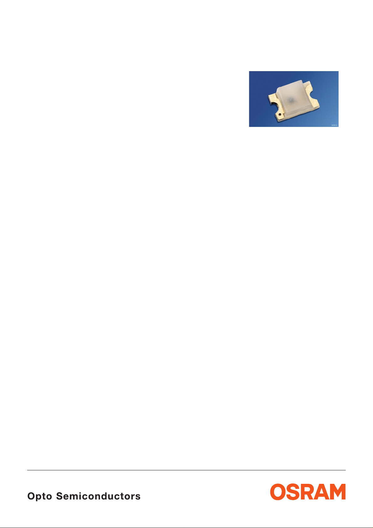
Hyper CHIPLED
Hyper-Bright LED
LS R976, LO R976, LY R976
Besondere Merkmale
• Gehäusetyp: 0805
• Besonderheit des Bauteils: extrem kleine
Bauform 2,0 mm x 1,25 mm x 0,8 mm
• Wellenlänge: 632 nm (super-rot),
605 nm (orange), 587 nm (gelb)
• Abstrahlwinkel: extrem breite
Abstrahlcharakteristik (160°)
• Technologie: InGaAlP
• optischer Wirkungsgrad: 7 lm/W (super-rot),
11 lm/W (orange, gelb)
• Verarbeitungsmethode: für alle
SMT-Bestücktechniken geeignet
• Lötmethode: IR Reflow Löten
• Vorbehandlung: nach JEDEC Level 2
• Gurtung: 8 mm Gurt mit 4000/Rolle, ø180 mm
Anwendungen
• Informationsanzeigen im Außenbereich
• Einkopplung in Lichtleiter
• Hinterleuchtung (LCD, Handy, Schalter,
Tasten, Displays, Werbebeleuchtung,
Allgemeinbeleuchtung)
• Signal- und Symbolleuchten
• Markierungsbeleuchtung (z.B. Stufen,
Fluchtwege, u.ä.)
• Spielsachen
Features
• package: 0805
• feature of the device: extremely small
package 2.0 mm x 1.25 mm x 0.8 mm
• wavelength: 632 nm (super-red),
605 nm (orange), 587 nm (yellow)
• viewing angle: extremely wide (160°)
• technology: InGaAlP
• optical efficiency: 7 lm/W (super-red),
11 lm/W (orange, yellow)
• assembly methods: suitable for all
SMT assembly methods
• soldering methods: IR reflow soldering
• preconditioning: acc. to JEDEC Level 2
• taping: 8 mm tape with 4000/reel, ø180 mm
Applications
• outdoor displays
• coupling into light guides
• backlighting (LCD, cellular phones, switches,
keys, displays, illumina ted advertisi ng, gen eral
lighting)
• signal and symbol luminaire
• marker lights (e.g. steps, exit ways, etc.)
• toys
2001-01-22 1
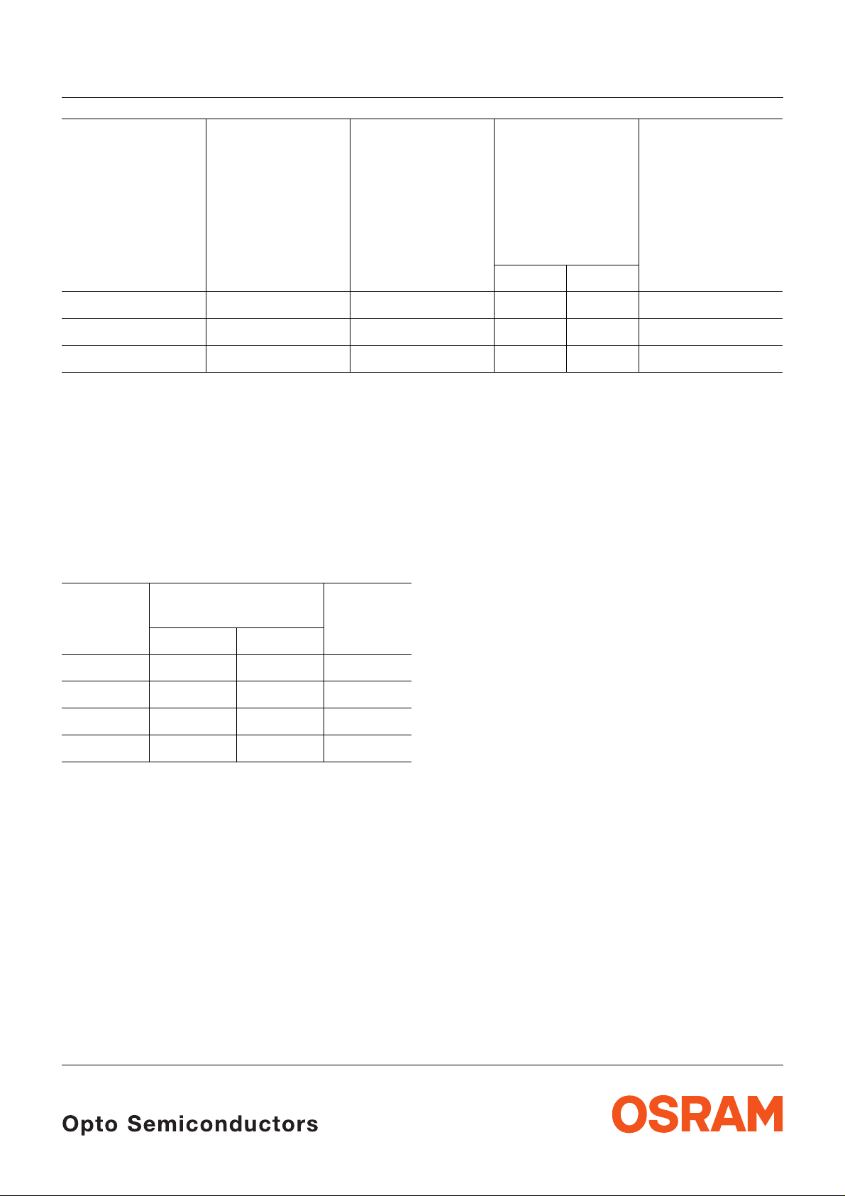
LS R976, LO R976, LY R976
Typ
Emissionsfarbe
Farbe der
Lichtstärke
Bestellnummer
Lichtaustrittsfläche
Type
Color of
Emission
Color of the
Light Emitting
Area
Luminous
Intensity
I
= 20 mA
F
I
(mcd)
V
Ordering Code
min. typ.
LS R976 super-red colorless diffused 18 50 Q62702-P5178
LO R976 orange colorless diffused 28 70 Q62702-P5176
LY R976 yellow colorless diffused 28 60 Q62702-P5177
Helligkeitswerte werden mit einer Stromeinprägedauer von 25 ms und einer Genauigkeit von ±11 %
ermittelt.
Luminous intensity is tested at a current pulse duration of 25 ms and an accuracy of ±11 %.
Wellenlängengruppen für LY R976
Wavelength groups for LY R976
Gruppe
Group
Wellenlänge
Wavelength
Einheit
Unit
min. max.
3 580 584 nm
4 584 588 nm
5 588 592 nm
6 592 596 nm
Wellenlängen werden mit einer Stromeinprägedauer von 25 ms und einer Genauigkeit von ±1,0 nm
ermittelt.
Wavelengths are tested at a current pulse duration of 25 ms and an accuracy of ±1.0 nm.
2001-01-22 2
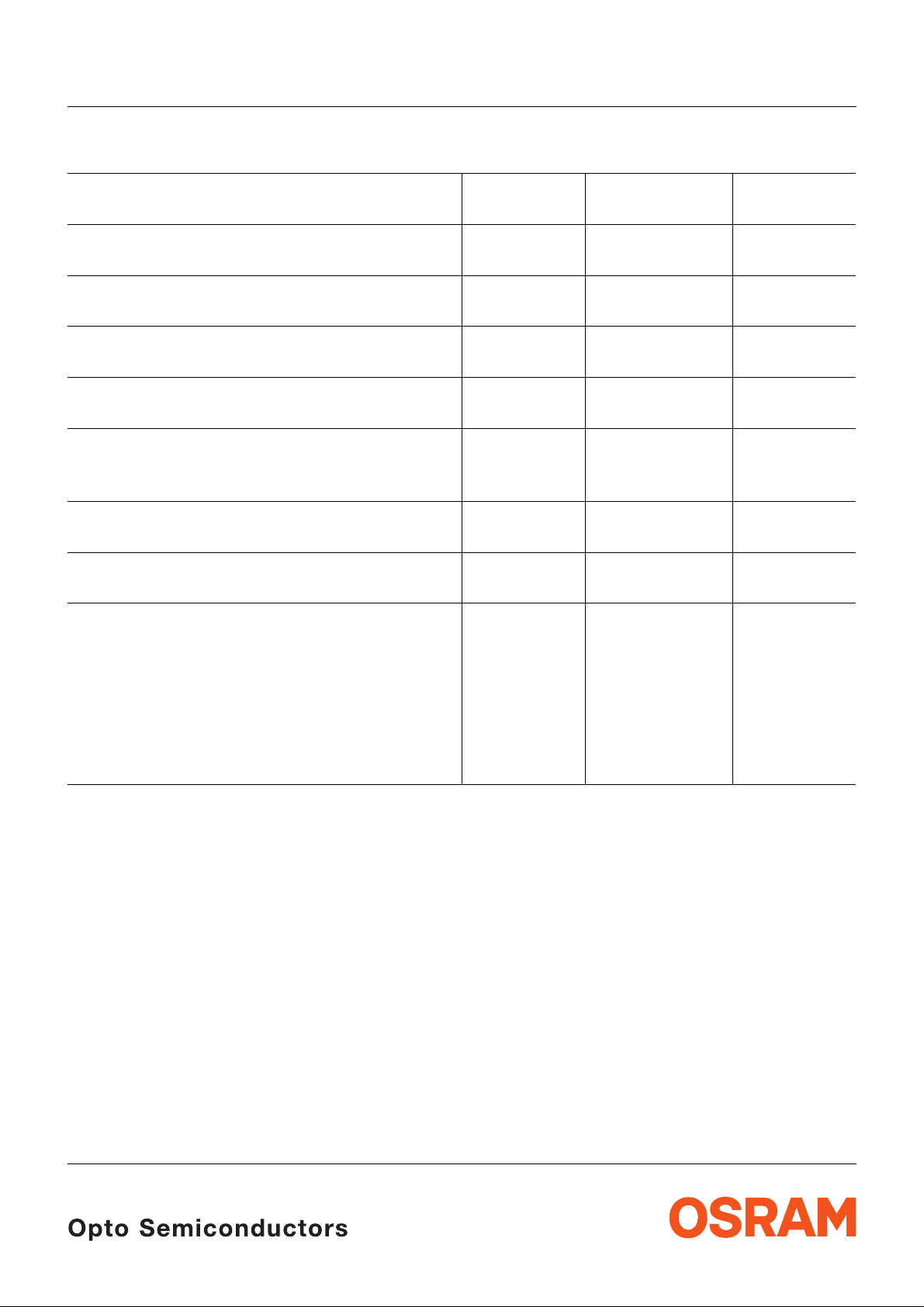
Grenzwerte
Maximum Ratings
LS R976, LO R976, LY R976
Bezeichnung
Parameter
Betriebstemperatur
Operating temperature range
Lagertemperatur
Storage temperature range
Sperrschichttemperatur
Junction temperature
Durchlassstrom
Forward current
Stoßstrom
Surge current
t
= 10 µs, D = 0.1
p
Sperrspannung
Reverse voltage
Leistungsaufnahme
Power dissipation
Wärmewiderstand
Thermal resistance
Sperrschicht/Umgebung
Junction/ambient
Sperrschicht/Lötpad
Junction/solder point
Montage auf PC-Board FR 4 (Padgröße
mounted on PC board FR 4 (pad size
≥ 16 mm
≥ 16 mm
2
)
2
)
Symbol
Symbol
T
op
T
stg
T
j
I
F
I
FM
V
R
P
tot
R
th JA
R
th JS
Wert
Value
Einheit
Unit
– 30 … + 85 °C
– 40 … + 85 °C
+ 95 °C
25 mA
t.b.d. A
5V
65 mW
800
450
K/W
K/W
2001-01-22 3

Kennwerte (TA = 25 °C)
Characteristics
LS R976, LO R976, LY R976
Bezeichnung
Parameter
Wellenlänge des emittierten Lichtes (typ.)
Wavelength at peak emission
I
= 20 mA
F
Dominantwellenlänge (typ.)
Dominant wavelength
I
= 20 mA
F
I
Spektrale Bandbreite bei 50 %
Spectral bandwidth at 50 %
I
= 20 mA
F
Abstrahlwinkel bei 50 %
Viewing angle at 50 %
I
rel max
I
(Vollwinkel) (typ.)
V
I
V
(typ.)
rel max
Durchlassspannung (typ.)
Forward voltage (max.)
I
= 20 mA
F
Sperrstrom (typ.)
Reverse current (max.)
V
= 5 V
R
Temperaturkoeffizient von
Temperature coefficient of
I
= 20 mA
F
Temperaturkoeffizient von
Temperature coefficient of
I
= 20 mA
F
Temperaturkoeffizient von
Temperature coefficient of
I
= 20 mA
F
V
λ
λ
λ
λ
V
peak
peak
dom
dom
F
F
(typ.)
(typ.)
(typ.)
Optischer Wirkungsgrad (typ.)
Optical efficiency
I
= 20 mA
F
Symbol
Symbol
Werte
Values
Einheit
Unit
LS LO LY
λ
λ
peak
dom
645 610 591 nm
632 605 587 nm
∆λ 16 16 15 nm
2ϕ 160 160 160 Grad
deg.
V
V
I
R
I
R
TC
TC
TC
η
opt
F
F
λpeak
λdom
V
2.0
2.5
0.01
100
2.0
2.5
0.01
100
2.0
2.5
0.01
100
V
V
µA
µA
0.14 0.13 0.13 nm/K
0.01 0.07 0.10 nm/K
– 2.0 – 1.7 – 2.5 mV/K
71111lm/W
2001-01-22 4

LS R976, LO R976, LY R976
Relative spektrale Emission I
rel
Relative Spectral Emission
λ) = spektrale Augenempfindlichkeit
V(
Standard eye response curve
100
%
Ι
rel
80
60
40
20
= f (λ), TA = 25 °C, IF = 20 mA
V
λ
yellow
orange
OHL00555
super-red
0
400
Abstrahlcharakteristik
Radiation Characteristic
50˚
60˚
70˚
80˚
90˚
I
= f (ϕ)
rel
nm450 500 550 600 650 700
λ
0˚10˚20˚40˚ 30˚
ϕ
1.0
0.8
0.6
0.4
0.2
0
OHL00408
100˚
1.0 0.8 0.6 0.4
2001-01-22 5
0˚ 20˚ 40˚ 60˚ 80˚ 100˚ 120˚

LS R976, LO R976, LY R976
Durchlassstrom IF = f (VF)
Forward Current
T
= 25 °C
A
2
10
mA
5
10
10
1
5
0
5
I
F
OHL00232
-1
10
1
1.4 1.8 2.2 2.6 3 V 3.4
V
F
Maximal zulässiger Durchlassstrom
Max. Permissible Forward Current
30
mA
25
I
F
20
15
OHL00420
I
= f (T)
F
Relative Lichtstärke
I
V/IV(20 mA)
Relative Luminous Intensity
T
= 25 °C
A
Ι
V (20 mA)
Relative Lichtstärke
10
Ι
V
10
5
10
5
10
5
10
1
0
-1
super-red,
-2
-3
orange
-2
10 10
-1
yellow
0
I
V/IV(25 °C)
Relative Luminous Intensity
I
= 20 mA
F
2
I
V
I
V (25 ˚C)
1.6
1.2
orange
yellow
super-red
= f (IF)
OHL00642
1010
= f (TA)
mA110
Ι
F
OHL00641
2
10
5
0
10020
2001-01-22 6
4030 50 70
60
80
°C
100
T
A
0.8
0.4
0
-20 0
orange
yellow
super-red
20 40 60 ˚C 100
T
A

Maßzeichnung
Package Outlines
LS R976, LO R976, LY R976
1.35 (0.053)
ø0.6 (ø0.024)
1.15 (0.045)
ø0.4 (ø0.016)
Cathode
mark
Maße werden wie folgt angegeb en: m m (inch) / Dimensions are specified as follo w s: m m (i nc h).
0.4 (0.016)
0.2 (0.008)
2.1 (0.083)
1.9 (0.075)
0.9 (0.035)
0.7 (0.028)
1.4 (0.055)
1.2 (0.047)
0.3 (0.012)
0.5 (0.020)
0.9 (0.035)
1.1 (0.043)
Soldering terminal
may flow in x, y direction
1.25 (0.049)
1.05 (0.041)
Cathode mark
GEOY6024
2001-01-22 7

Lötbedingungen Vorbehandlung nach JEDEC Level 2
Soldering Conditions Preconditioning acc. to JEDEC Level 2
IR-Reflow Lötprofil (nach IPC 9501)
IR Reflow Soldering Profile (acc. to IPC 9501)
LS R976, LO R976, LY R976
250
˚C
T
200
150
100
50
0
0:00
2-3 K/s
0:30 1:00 1:30 2:00 2:30 3:00 3:30 4:00 4:30 5:00 5:30
T
= 183 ˚C = 70 s
t
T
max
= 245 ˚C
2-3 K/s
OHLA0685
min
t
Empfohlenes Lötpaddesign IR Reflow Löten
Recommended Solder Pad IR Reflow Soldering
1.2 (0.047)
1.2 (0.047)
Maße werden wie folgt angegeb en: m m (inch) / Dimensions are specified as follo w s: m m (i nc h)
2001-01-22 8
0.9 (0.035)
1.2 (0.047)

LS R976, LO R976, LY R976
Gurtung / Polarität und Lage Verpackungseinheit 4000/Rolle, ø180 mm
Method of Taping / Polarity and Orientation Packing unit 4000/reel, ø180 mm
Processive direction
1.5 (0.059)
4 (0.157)
1.6 (0.063)
Cathode mark
Maße werden wie folgt angegeb en: m m (inch) / Dimensions are specified as follo w s: m m (i nc h).
2 (0.079)
4 (0.157)
1.75 (0.069)
3.5 (0.138)
(2.4 (0.094))
8 (0.315)
OHAY0530
C
A
2001-01-22 9
 Loading...