

Page 1
LS/PD MULTI 3 B
Light and motion sensor
Fitting instructions
Description
Function and application
The LS/PD MULTI 3 B sensor detects the presence of people
and measures the intensity of ambient light.
The sensor is installed in lamps.
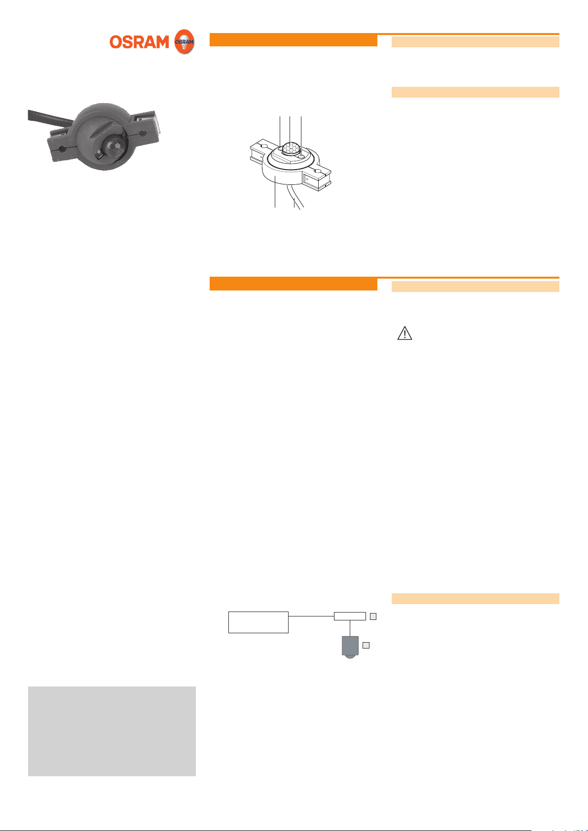
Construction
CA B
E
D
The sensor is made up of the following components:
• LED (A)
• Motion sensor (B)
• Light sensor (C)
• Connection cable (D)
• Housing (E)
Installation
Safety instructions
The sensor must only be installed and put into operation by a
qualied electrician. The applicable safety regulations and ac-
cident prevention regulations must be observed.
WARNING!
Exposed, live cables or damaged housing.
Danger of electric shock!
• Only work on the sensor when it is de-energized.
CAUTION!
Destruction of the sensor and other devices through
incorrect mounting!
• Only use OSRAM control units of the following
types: DALI MULTI 3/ DIM MULTI 3, DALI
MULTIeco/ MULTIeco, DALI PROFESSIONAL
Sensor Coupler.
• Do not connect control line with external voltage.
• Note the maximum total line length.
• Do not route the sensor line together with the
power or lamp line.
II 2009
LSPD_Multi3-B_ma0902en_we1.01.indd
OSRAM GmbH
Kunden Service Center
Customer-Service-Center (CSC)
Steinerne Furt 62
86167 Augsburg
Germany
Tel : +49 (0) 1803 677 - 200
(kostenpichtig / charges apply)
Fax.: +49 (0) 1803 677 - 202
www.osram.com
www.osram.de
40503008030812
4050300803081
DALI MULTI 3
Sensor
Connecting the sensor
Connect the sensor using the supplied cable or a commercially
F
available 4-pin cable. If the cable is shortened or lengthened,
ensure that the wiring is correct.
Sensors can be connected in parallel via a Y-branch. For the
maximum number of sensors: see the separate control unit
G
manual.
F Y-branch
G Sensor
Continued on the back page!
Page 2
Fitting (cont.)
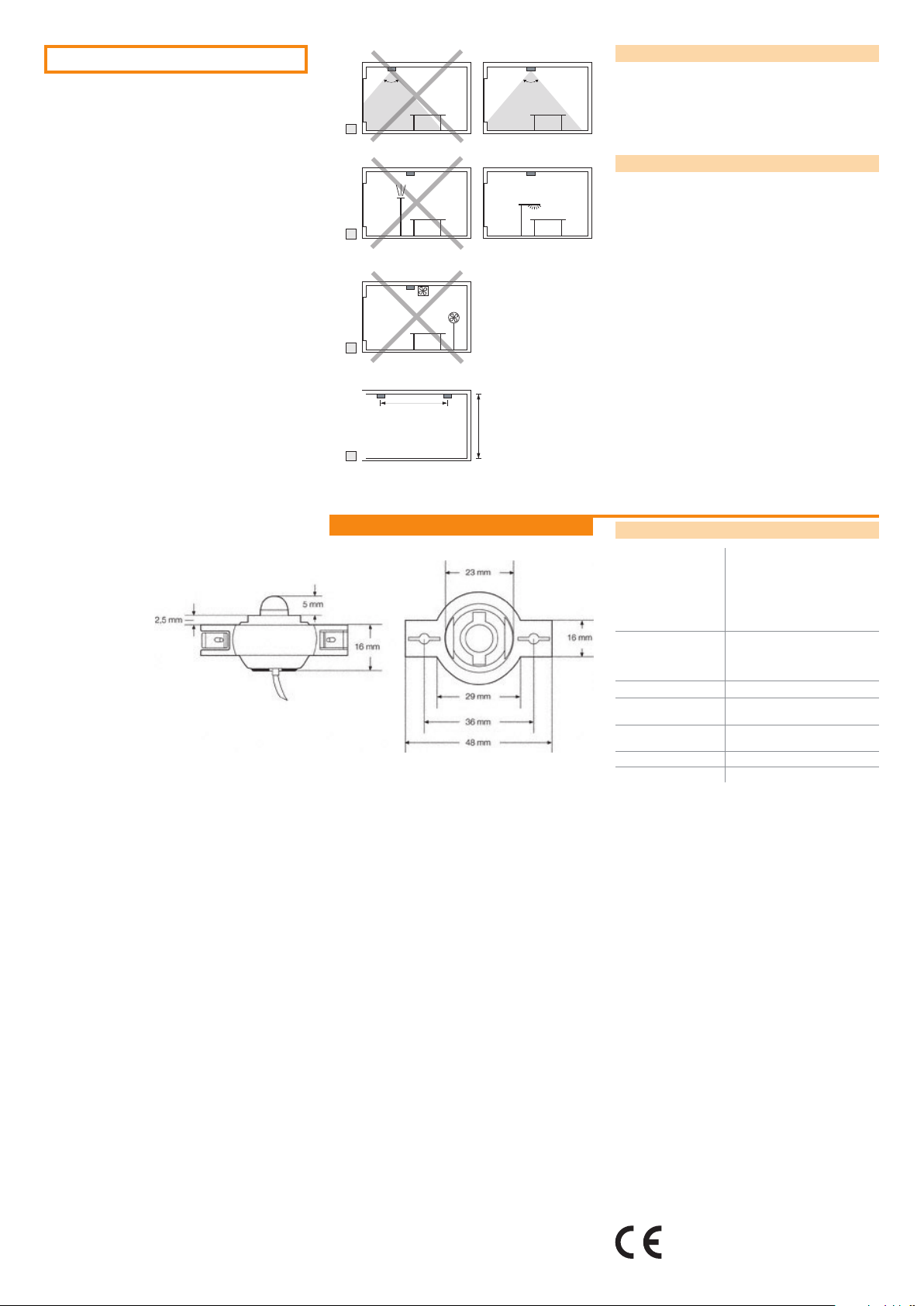
Selecting the installation location
H Surveillance cone: entire workplace; not on window sur-
80°
H
80°
faces.
I Avoid exposure to direct light.
K Avoid drafts (e.g. from ventilators or fans).
L Installation distance = min. installation height
Adjusting the detection area
Tilt the motion sensor up to 30° in the required direction.
I
K
> h
h
L
Appendix
Technical data
Combined control and
supply connection
Maximum total length
of signal line (incl. all
connections to the
control units)
Insulation Basic insulation as per IEC 664
Dimensions
(L x W x H)
Light sensor detection
area
Motion detection area Conical, opening angle approx. 80°
Installation height 2 - 4 m
4-pin modular connection (4p4c)
1: Supply voltage
2: Light measurement value
3: Motion signal
4: Signal ground
Length 2.1 m
See control unit
48 x 29 x 24.5 mm
20 - 600 lx (measured at sensor),
opening angle approx. 90°
The CE requirements to EN 60928 are fullled.
The EMC requirements to EN 61547 are fullled.
Conformity with the relevant EU directives is
conrmed by the CE symbol.
 Loading...