

Page 1
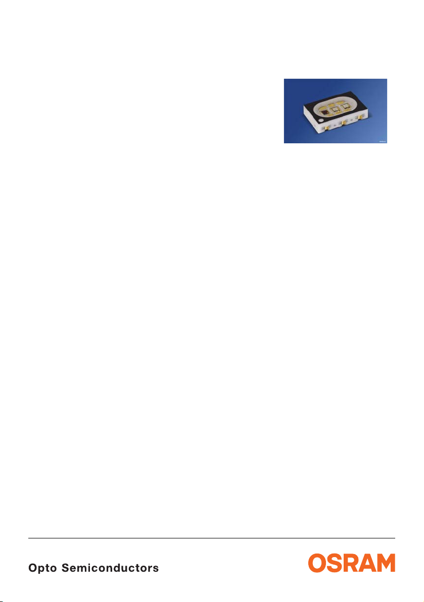
Multi CERAMOS
Enhanced optical Power LED (ThinFilm / ThinGaN)
Lead (Pb) Free Product - RoHS Compliant
LRTB C9TP
Vorläufige Daten / Preliminary Data
Besondere Merkmale
• Gehäusetyp: Keramik Gehäuse für
RGB-Anzeigen mit diffusem Silikon Verguss.
• Besonderheit des Bauteils: additive
Farbmischung durch unabhängige Ansteuerung
aller Chips; Kontrasterhöhung durch schwarze
Oberfläche (RGB-Displays)
• Wellenlänge: 625 nm (rot), 528 nm (true green),
470 nm (blau)
• Abstrahlwinkel: Lambertscher Strahler (120°)
• Technologie: ThinFilm (rot),
ThinGaN
• optischer Wirkungsgrad: 45 lm/W (rot),
45
• Gruppierungsparameter: Lichtstärke,
Wellenlänge
• Verarbeitungsmethode: für alle
SMT-Bestücktechniken geeignet
• Lötmethode: Reflow Löten
• Vorbehandlung: nach JEDEC Level 2
• Gurtung: 12 mm Gurt mit 1000/Rolle, ø180 mm
• ESD-Festigkeit: ESD-sensitives Bauteil
Anwendungen
• Anzeigen im Innen- und Außenbereich
(z.B. im Verkehrsbereich; Laufschriftanzeigen)
• Getrennte Anteuerung der Leuchtdiodenchips zur
Darstellung verschiedener Farben inclusive weiß
• Vollfarbdisplays bzw. RGB-Displays
• Hinterleuchtung (LCD, Schalter, Tasten,
Werbebeleuchtung, Allgemeinbeleuchtung)
• Einkopplung in Lichtleiter
(true green, blau)
lm/W (true green), 15 lm/W (blau)
Features
• package: ceramic package for RGB-Displays
with diffused silicon resin.
• feature of the device: additive mixture of color
stimuli by independent driving of each chip; higher
contrast by a black surface (RGB-Displays)
• wavelength: 625 nm (red), 528 nm (true green),
470 nm (blue)
• viewing angle: Lambertian Emitter (120°)
• technology: ThinFilm (red),
ThinGaN
• optical efficiency: 45 lm/W (red),
45
• grouping parameter: luminous intensity,
wavelength
• assembly methods: suitable for all
SMT
• soldering methods: reflow soldering
• preconditioning: acc. to JEDEC Level 2
• taping: 12 mm tape with 1000/reel, ø180 mm
• ESD-withstand voltage: ESD senitive Device
Applications
• indoor and outdoor displays (e.g. displays for
traffic; light writing displays)
• LED chips can be controlled seperately to display
various colors including white
• full color displays, RGB-Displays
• backlighting (LCD, switches, keys, illuminated
advertising, general lighting)
• coupling into light guides
(true green, blue)
lm/W (true green), 15 lm/W (blue)
assembly methods
2010-02-26 1
Page 2
LRTB C9TP
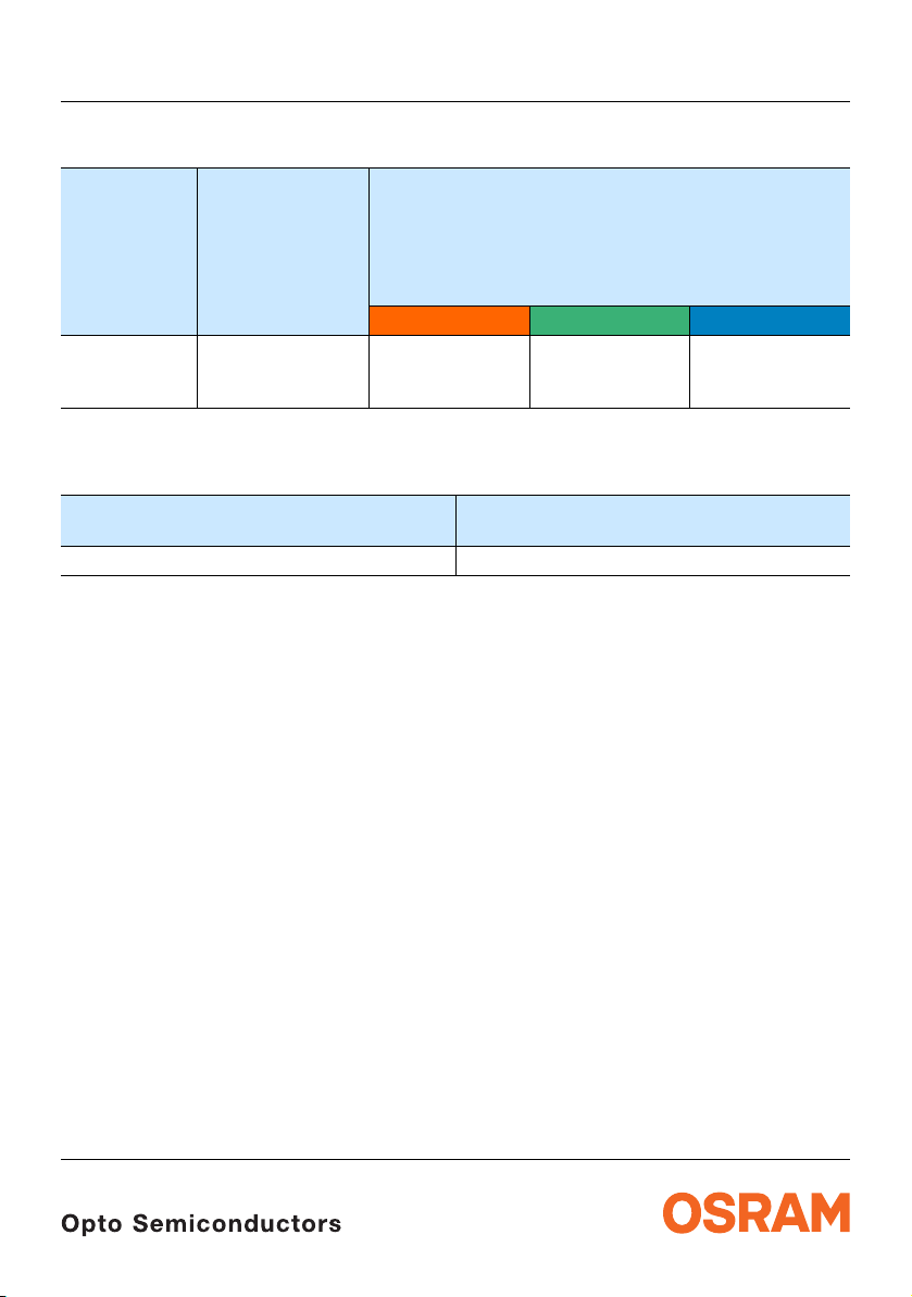
Bestellinformation Ordering Information
1)
Seite 26
Typ
Type
Emissionsfarbe
Color of Emission
Lichtstärke
Luminous Intensity
I
= 140 mA
F
I
(mcd)
V
red true green blue
LRTB C9TP red
2.800...8.000
true green
blue
Bestellinformation Ordering Information
Typ
Type
LRTB C9TP-CWD5-1+D5E7-25+A9C5-49 Q65110A8879
Anm.: Die oben genannten Typbezeichnungen umfassen die bestellbaren Selektionen. Diese bestehen
aus wenigen Helligkeitsgruppen (siehe Seite 7 für nähere Informationen). Es wird nur eine
einzige Helligkeitsgruppe pro Gurt geliefert. Z.B.: LRTB C9TP-CWD5-1+D5E7-25+A9C5-49
bedeutet, dass auf dem Gurt nur eine der Helligkeitsgruppen CW, C5, C7, C9, DW oder D5
enthalten ist.
Um die Liefersicherheit zu gewährleisten, können einzelne Helligkeitsgruppen nicht bestellt
werden.
Gleiches gilt für die Farben, bei denen Wellenlängengruppen gemessen und gruppiert werden.
Pro Gurt wird nur eine Wellenlängengruppe geliefert. Z.B.:
LRTB
Wellenlängengruppen -2, -3, -4 oder -5 enthalten ist (siehe
Z.B.:LRTB C9TP-CWD5-1+D5E7-25+A9C5-49 bedeutet, dass das Bauteil innerhalb der auf
Seite 4 spezifizierten Grenzen geliefert wird.
Um die Liefersicherheit zu gewährleisten, können einzelne Wellenlängengruppen nicht bestellt
werden.
C9TP-CWD5-1+D5E7-25+A9C5-49 bedeutet, dass auf dem Gurt nur eine der
1) page 26
5.000 ...14.000
Bestellnummer
Ordering Code
1.590 ...5.000
Seite 8 für nähere Information).
Note: The above Type Numbers represent the order groups which include only a few brightness groups
page 7 for explanation). Only one group will be shipped on each reel (there will be no mixing
(see
of two groups on each reel). E.g. LRTB C9TP-CWD5-1+D5E7-25+A9C5-49 means that only one
group CW, C5, C7, C9, DW or D5 will be shippable for any one reel.
In order to ensure availability, single brightness groups will not be orderable.
In a similar manner for colors where wavelength groups are measured and binned, single
wavelength groups will be shipped on any one reel. E.g.
LRTB
C9TP-CWD5-1+D5E7-25+A9C5-49 means that only 1 wavelength group -2, -3, -4 or -5 will
be shippable (see page 8 for explanation). E.g. LRTB C9TP-CWD5-1+D5E7-25+A9C5-49
means that the device will be shiped within the specified limits as stated on page 4.
In order to ensure availability, single wavelength groups will not be orderable.
2010-02-26 2
Page 3
LRTB C9TP
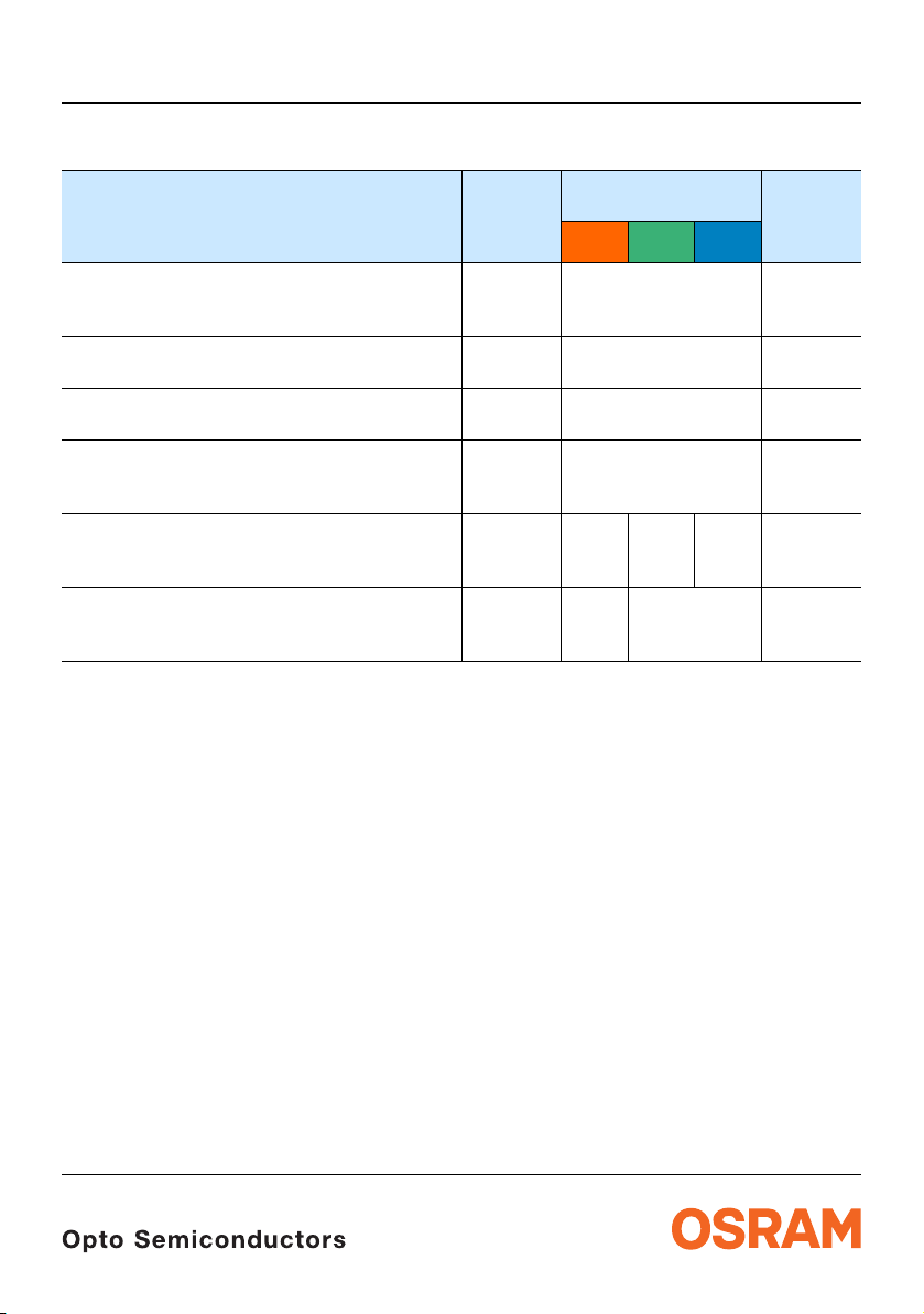
Grenzwerte Maximum Ratings
Bezeichnung
Parameter
Betriebstemperatur (auf PC-Board FR4/G30)
Operating temperature range
(on PC-Board FR4/G30)
Lagertemperatur
Storage temperature range
Sperrschichttemperatur
Junction temperature
Durchlassstrom (min.)
Forward current (max.)
(TS=25°C)
Stoßstrom
Surge current
t
= 10 μs, D = 0.005, TS=25°C
p
Sperrspannung
Reverse voltage
2)
Seite 26
2) page 26
(TS=25°C)
*auf Grund von unterschiedlichen thermischen Ausdehnungskoeffizienten nicht empfehlenswert für
MCPCB
on MCPCB not recommended due to thermal mismatch issue
Symbol
Symbol
T
op
T
stg
T
j
I
F
I
F
I
FM
V
R
Werte
Values
red true
green
blue
Einheit
Unit
– 40 … + 110* °C
– 40 … + 110 °C
+ 150 °C
30
mA
250
1000 750 750 mA
12 5 V
2010-02-26 3
Page 4
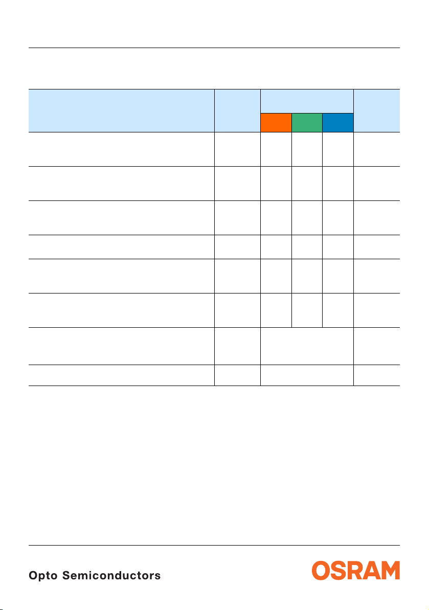
Kennwerte
Characteristics
(TS = 25 °C)
Bezeichnung
Parameter
Wellenlänge des emittierten Lichtes (typ.)
Wavelength at peak emission
I
= 140 mA
F
Dominantwellenlänge
Dominant wavelength
I
= 140 mA (max.)
F
Spektrale Bandbreite bei 50 % I
Spectral bandwidth at 50 % I
I
= 140 mA
F
3)
Seite 26
3) page 26
rel max
rel max
(min.)
(typ.)
(typ.)
Abstrahlwinkel bei 50 % IV (Vollwinkel) (typ.)
Viewing angle at 50 % I
Durchlassspannung
Forward voltage
I
= 140 mA (max.)
F
4)
4) page 26
V
Seite 26
(min.)
(typ.)
Sperrstrom (typ.)
Reverse current (max.)
V
= 5 V (blue / true green); 12 V (red)
R
Wärmewiderstand
Thermal resistance
Sperrschicht/Lötpad 1 chip on (typ.)
Junction/solder point 1 chip on (max.)
Sperrschicht/Lötpad 3 chip on (typ.)
Junction/solder point 3 chip on (max.)
* Einzelgruppen siehe Seite 8
Individual groups on page 8
**Rth(max) basiert auf statistischen Werten
Rth(max) is based on statistic values
LRTB C9TP
Symbol
Symbol
red true
λ
peak
λ
dom
632 523 465 nm
619
625
631
Δλ 18 33 25 nm
2ϕ 120 120 120 Grad
V
F
V
F
V
F
I
R
I
R
R
th JS
R
th JS
R
th JS
R
th JS
1.9
2.1
2.65
0.01 100.01 100.01
Werte
Values
green
518
528*
544
2.9
3.4
4.1
41
55
50
82
blue
459
470*
476.5
2.9
3.3
4.1
10
Einheit
Unit
nm
nm
nm
deg.
V
V
V
μA
μA
K/W
K/W
K/W
K/W
2010-02-26 4
Page 5
5) Seite 26
OHA04233
520
530
540
550
560
570
580
590
600
610
620
630
0
0
0.1
0.2
0.3
0.4
0.5
0.6
0.7
0.8
0.9
0.1 0.2 0.3 0.4 0.5 0.6 0.7 0.8 0.9
510
505
500
495
490
485
480
460
true green
blue
red
23 4
6
5
5
4
1
7
8
9
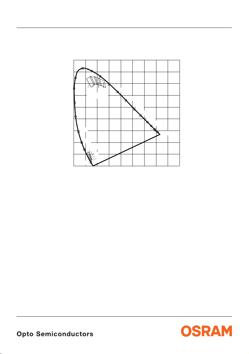
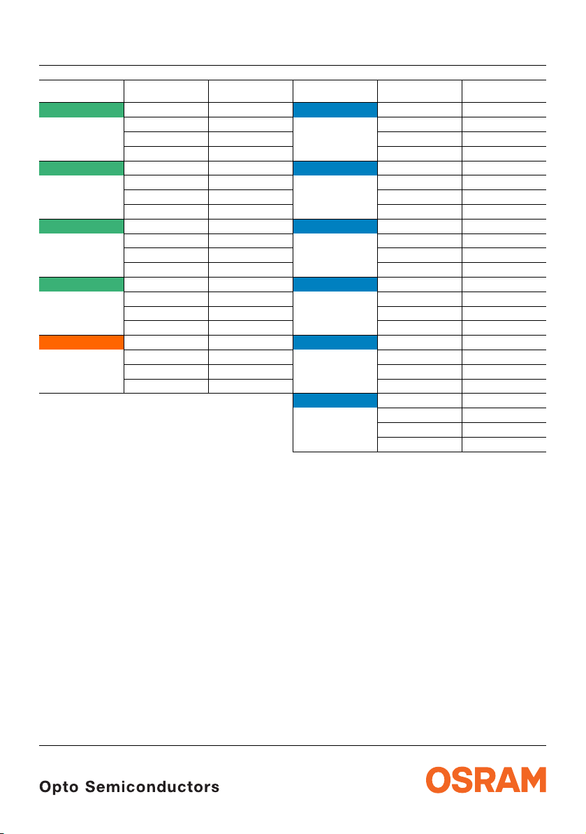
Farbortgruppen
Chromaticity Coordinate Groups
5) page 26
LRTB C9TP
7
2010-02-26 5
Page 6
LRTB C9TP
Gruppe
Group
2 0.109 0.739 4 0.146 0.029
3 0.139 0.757 5 0.142 0.034
4 0.173 0.759 6 0.138 0.039
5 0.209 0.748 7 0.134 0.046
1 0.689 0.310 8 0.129 0.056
Anm.: Die Farbkoordinaten des Mischlichtes können innerhalb des gekennzeichneten Bereichs des Farbdreiecks erwartet werden.
Note: The color coordinates of the mixed light can be expec ted within the marked area of the color triangle
Cx Cy Gruppe
0.148 0.670 0.157 0.047
0.178 0.694 0.152 0.058
0.148 0.763 0.139 0.038
0.171 0.688 0.155 0.053
0.206 0.695 0.149 0.065
0.184 0.757 0.135 0.044
0.198 0.692 0.151 0.059
0.238 0.682 0.145 0.075
0.221 0.743 0.129 0.053
0.228 0.685 0.149 0.067
0.271 0.665 0.141 0.087
0.260 0.723 0.123 0.065
0.677 0.311 0.145 0.078
0.696 0.292 0.137 0.103
0.709 0.291 0.118 0.081
Group
9 0.122 0.068
Cx Cy
0.140 0.090
0.132 0.121
0.110 0.099
2010-02-26 6
Page 7
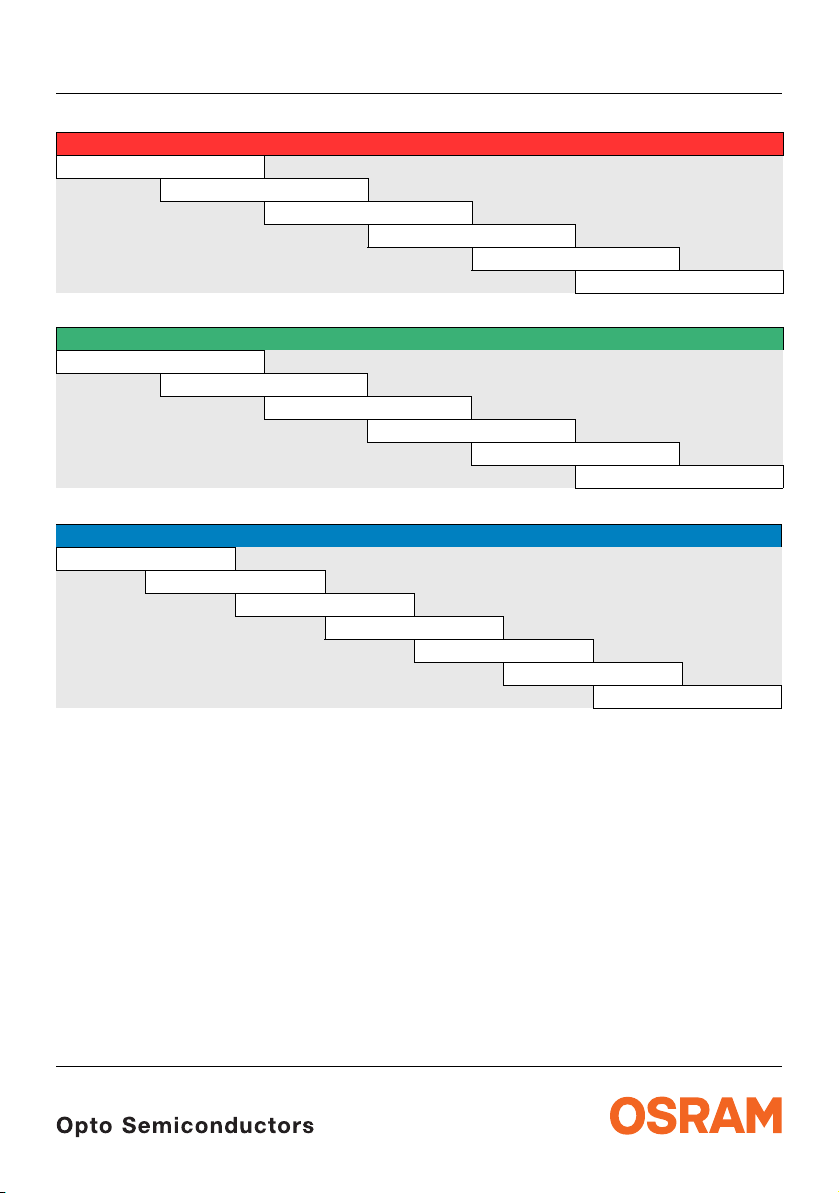
Floating Bins
CW = 2.800... 4.500 [mcd]
Floating Bins
D5 = 5.020... 7.994 [mcd]
Floating Bins
A9 = 1.590... 2.500 [mcd]
LRTB C9TP
red
C5 = 3.153 ... 5.000 mcd]
C7 = 3.550... 5.600 [mcd]
C9 = 4.000... 6.300 [mcd]
DW = 4.500.. 7.100 [mcd]
D5 = 5.000... 8.000 [mcd]
true green
D7 = 5.600 ... 9.000 [mcd]
D9 = 6.300 ... 10.000 [mcd]
EW = 7.100 ... 11.200 [mcd]
E5 = 8.000 ... 12.000 [mcd]
E7 = 9.000 ... 14.000 [mcd]
blue
BW = 1.800... 2.800 [mcd]
B5 = 2.010... 3.150 [mcd]
B7 = 2.440... 3.550 [mcd]
B9 = 2.500... 4.000 [mcd]
CW = 2.800... 4.500 [mcd]
C5 = 3.150...5.000 [mcd]
2010-02-26 7
Page 8
LRTB C9TP
3) Seite 26
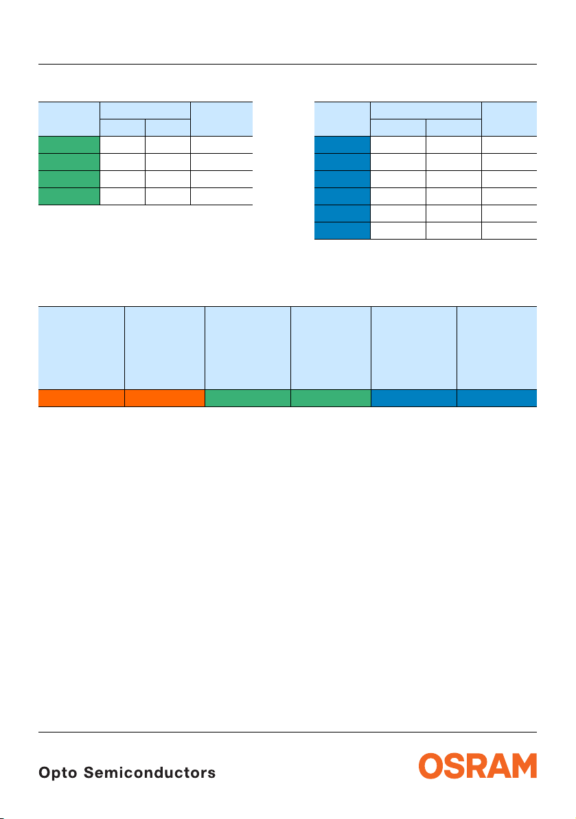
Wellenlängengruppen (Dominantwellenlänge)
Wavelength Groups (Dominant Wavelength)
Gruppe
Group
true green Einheit
min. max. min. max.
Unit
2 518 526 nm 4 459.0 463.5 nm
3 524 532 nm 5 461.5 466.0 nm
4 530 538 nm 6 464.0 468.5 nm
5 536 544 nm 7 466.5 471.0 nm
Gruppenbezeichnung auf Etikett
Group Name on Label
Beispiel: CW-1+DW-2+A79-3
Example: CW-1+DW-2+A9-3
Helligkeitsgruppe
Brightness
Group
(red)
Wellenlänge
(keine
Gruppierung)
Wavelength
(no grouping)
(red)
Helligkeitsgruppe
Brightness
Group
(true green)
CW 1 D5 2 A9 4
Anm.: In einer Verpackungseinheit / Gurt ist immer nur eine Helligkeitsgruppe pro Farbe enthalten.
Note: No packing unit / tape ever contains more than one brightness group per color.
3) page 26
Gruppe
Group
8 469.0 473.5
9 471.5 476.0
Wellenlänge
Wavelength
(true green)
Helligkeitsgruppe
Brightness
Group
(blue)
blue Einheit
Wellenlänge
Wavelength
(blue)
Unit
2010-02-26 8
Page 9

5)
40
0
400
20
60
80
rel
I
100
%
nm
λ
OHL02514
V
λ
450 500 550 600 650 700
blue
true green
red
0
0.2
0.4
1.0
0.8
0.6
ϕ
1.0 0.8 0.6 0.4
0˚10˚20˚40˚ 30˚
OHL01660
50˚
60˚
70˚
80˚
90˚
100˚
0˚ 20˚ 40˚ 60˚ 80˚ 100˚ 120˚
Seite 26
Relative spektrale Emission
Relative Spectral Emission
5) page 26
V(λ) = spektrale Augenempfindlichkeit / Standard eye response curve
I
= f (λ); TS = 25 °C; IF = 140 mA
rel
5)
Seite 26
Abstrahlcharakteristik
Radiation Characteristic
I
= f (ϕ); TS = 25 °C
rel
5) page 26
LRTB C9TP
2010-02-26 9
Page 10

LRTB C9TP
OHL04234
F
I
V
mA
1.7
F
V
0
50
100
150
200
250
1.8 1.9 2 2.1 2.2 2.4
OHL04236
F
I
V
mA
2.7
F
V
0
50
100
150
200
250
2.9 3.1 3.3 3.5
OHL04235
F
I
V
mA
2.7
F
V
0
50
100
150
200
250
2.9 3.1 3.3 3.5 3.7
Durchlassstrom
Forward Current
I
= f (VF); TS = 25 °C, red
F
solid line: specified DC-range
Durchlassstrom
Forward Current
I
= f (VF); TS = 25 °C, blue
F
solid line: specified DC-range
6) Seite 26
6) page 26
6) Seite 26
6) page 26
Durchlassstrom
Forward Current
I
= f (VF); TS = 25 °C, true green
F
solid line: specified DC-range
6) Seite 26
6) page 26
2010-02-26 10
Page 11

LRTB C9TP
OHL04237
I
F
mA
V
(140 mA)
I
V
I
30
0.1
60 90 120 150 180 210 270
0.3
0.5
0.7
0.9
1.1
1.3
1.5
1.9
OHL04239
I
F
mA
V
(140 mA)
I
V
I
30060 90 120 150 180 210 270
0.2
0.4
0.6
0.8
1.0
1.2
1.6
OHL04238
I
F
mA
V
(140 mA)
I
V
I
30060 90 120 150 180 210 270
0.2
0.4
0.6
0.8
1.0
1.2
1.6
Relative Lichtstärke
6)7) Seite 26
Relative Luminous Intensity
Ι
(140 mA) = f (IF); TS = 25 °C; red
V/ΙV
Relative Lichtstärke
6)7) Seite 26
Relative Luminous Intensity
Ι
(140 mA) = f (IF); TS = 25 °C; blue
V/ΙV
6) 7) page 26
6) 7) page 26
Relative Lichtstärke
Relative Luminous Intensity
I
(140 mA) = f (IF); TS = 25 °C; true green
V/IV
6)7) Seite 26
6) 7) page 26
2010-02-26 11
Page 12

Relative Vorwärtsspannung
-0.5
T
j
OHL04242
V
F
V
Δ
120˚C6020 400-20-40 80
-0.4
-0.3
-0.2
-0.1
0
0.1
0.2
0.3
0.5
-0.5
T
j
OHL04244
V
F
V
Δ
120˚C6020 400-20-40 80
-0.4
-0.3
-0.2
-0.1
0
0.1
0.2
0.3
0.5
-0.5
T
j
OHL04243
V
F
V
Δ
120˚C6020 400-20-40 80
-0.4
-0.3
-0.2
-0.1
0
0.1
0.2
0.3
0.5
Relative Forward Voltage
ΔVF = VF - V
(25 °C); IF = 140 mA, red
F
Relative Vorwärtsspannung
Relative Forward Voltage
ΔVF = VF - V
(25 °C); IF = 140 mA, blue
F
6) page 26
6) page 26
6) Seite 26
6) Seite 26
LRTB C9TP
Relative Vorwärtsspannung
Relative Forward Voltage
ΔVF = VF - V
(25 °C); IF = 140 mA, true green
F
6) Seite 26
6) page 26
2010-02-26 12
Page 13

Relative Lichtstärke
OHL04245
-40 ˚C
j
T
-20 0 20 40 60 80 120
0
V
V
(25 ˚C)
I
I
0.2
0.4
0.6
0.8
1.0
1.2
1.6
OHL04247
-40 ˚C
j
T
-20 0 20 40 60 80 120
0
V
V
(25 ˚C)
I
I
0.2
0.4
0.6
0.8
1.2
OHL04246
-40 ˚C
j
T
-20 0 20 40 60 80 120
0
V
V
(25 ˚C)
I
I
0.2
0.4
0.6
0.8
1.2
6) Seite 26
Relative Luminous Intensity
Ι
(25 °C)= f (Tj); IF = 140 mA, red
V/ΙV
Relative Lichtstärke
6) Seite 26
Relative Luminous Intensity
I
(25 °C) = f (Tj); IF = 140 mA, blue
V/IV
6) page 26
6) page 26
LRTB C9TP
6) Seite 26
Relative Lichtstärke
Relative Luminous Intensity
I
(25 °C) = f (Tj); IF = 140 mA, true green
V/IV
6) page 26
2010-02-26 13
Page 14

Dominante Wellenlänge
-4
30
nm
F
mA
I
OHL04240
dom
Δλ
60 90 120 150 180 210 270
-2
0
2
4
6
8
10
-1.0
30
nm
F
mA
I
OHL04241
dom
Δλ
-0.5
0
0.5
1.0
1.5
2.0
3.0
60 90 120 150 180 210 270
Dominant Wavelength
λ
= f (IF); TS = 25 °C; true green
dom
6) page 26
6) Seite 26
LRTB C9TP
Dominante Wellenlänge
Dominant Wavelength
λ
= f (IF); TS = 25 °C; blue
dom
6) Seite 26
6) page 26
2010-02-26 14
Page 15

Dominante Wellenlänge6)
-6
nm
OHL04248
dom
Δλ
-4
-2
0
2
4
6
8
-20-40 602004080
T
j
˚C 120
-3
nm
OHL04250
dom
Δλ
-20-40 602004080
T
j
˚C 120
-2
-1
0
1
2
3
4
6
-1.0
nm
OHL04249
dom
Δλ
-20-40 602004080
T
j
˚C 120
-0.5
0
0.5
1.0
1.5
2.0
2.5
3.0
4.0
Dominant Wavelength
λ
= f (Tj); IF = 140 mA, red
dom
Dominante Wellenlänge
Dominant Wavelength
λ
= f (Tj); IF = 140 mA, blue
dom
6) page 26
6) page 26
Seite 26
6) Seite 26
LRTB C9TP
6) Seite 26
Dominante Wellenlänge
Dominant Wavelength
λ
= f (Tj); IF = 140 mA, true green
dom
6) page 26
2010-02-26 15
Page 16

LRTB C9TP
0
T
0
I
OHL04260
F
mA
20 40 60 80
120˚C
50
100
150
200
250
300
Do not use current below 30 mA
S
0
T
0
I
OHL04259
F
mA
20 40 60 80
120˚C
50
100
150
200
250
300
Do not use current below 30 mA
S
0
T
0
I
OHL04262
F
mA
20 40 60 80
120˚C
50
100
150
200
250
300
Do not use current below 30 mA
S
0
T
0
I
OHL04261
F
mA
20 40 60 80
120˚C
50
100
150
200
250
300
Do not use current below 30 mA
S
Maximal zulässiger Durchlassstrom
Max. Permissible Forward Current
I
= f (TS); (1 chip on); red
F
Maximal zulässiger Durchlassstrom
Max. Permissible Forward Current
I
= f (TS); (1 chip on); true green, blue
F
Maximal zulässiger Durchlassstrom
Max. Permissible Forward Current
I
= f (TS); (3 chips on); red
F
Maximal zulässiger Durchlassstrom
Max. Permissible Forward Current
I
= f (TS); (3 chips on); true green, blue
F
2010-02-26 16
Page 17

LRTB C9TP
1010
0
-2-3-4-5
1010 10
F
I
A
P
t
=
D
T
210-1
10
t
p
10 s 10
OHL04253
T
t
P
I
F
0.05
0.33
0.2
0.1
0.005
0.02
0.01
D
=
0.1
0.2
0.3
0.4
0.5
0.6
0.7
0.8
0.9
1.1
0.5
1
1010
0
-2-3-4-5
1010 10
F
I
A
P
t
=
D
T
210-1
10
t
p
10 s 10
OHL04251
T
t
P
I
F
0.05
0.33
0.5
1
0.2
0.1
0.005
0.02
0.01
D
=
0.1
0.2
0.3
0.4
0.5
0.6
0.8
0.7
1010
0
-2-3-4-5
1010 10
F
I
A
P
t
=
D
T
210-1
10
t
p
10 s 10
OHL04254
T
t
P
I
F
0.05
0.33
0.2
0.1
0.005
0.02
0.01
D
=
0.1
0.2
0.3
0.4
0.5
0.6
0.7
0.8
0.9
1.1
0.5
1
1010
0
-2-3-4-5
1010 10
F
I
A
P
t
=
D
T
210-1
10
t
p
10 s 10
OHL04252
T
t
P
I
F
0.05
0.33
0.5
1
0.2
0.1
0.005
0.02
0.01
D
=
0.1
0.2
0.3
0.4
0.5
0.6
0.8
0.7
Zulässige Impulsbelastbarkeit
Permissible Pulse Handling Capability
Duty cycle D = parameter, TS= 25 °C
I
= f (tp); (1 Chip on); red
F
Zulässige Impulsbelastbarkeit
Permissible Pulse Handling Capability
Duty cycle D = parameter, TS= 25 °C
I
= f (tp); (1 Chip on); true green, blue
F
Zulässige Impulsbelastbarkeit
Permissible Pulse Handling Capability
Duty cycle D = parameter, TS= 85 °C
I
= f (tp); (1 Chip on); red
F
Zulässige Impulsbelastbarkeit
Permissible Pulse Handling Capability
Duty cycle D = parameter, TS= 85 °C
I
= f (tp); (1 Chip on); true green, blue
F
2010-02-26 17
Page 18

LRTB C9TP
1010
0
-2-3-4-5
1010 10
F
I
A
P
t
=
D
T
210-1
10
t
p
10 s 10
OHL04257
T
t
P
I
F
0.05
0.33
0.2
0.1
0.005
0.02
0.01
D
=
0.1
0.2
0.3
0.4
0.5
0.6
0.7
0.8
0.9
1.1
0.5
1
1010
0
-2-3-4-5
1010 10
F
I
A
P
t
=
D
T
210-1
10
t
p
10 s 10
OHL04255
T
t
P
I
F
0.05
0.33
0.5
1
0.2
0.1
0.005
0.02
0.01
D
=
0.1
0.2
0.3
0.4
0.5
0.6
0.8
0.7
1010
0
-2-3-4-5
1010 10
F
I
A
P
t
=
D
T
210-1
10
t
p
10 s 10
OHL04258
T
t
P
I
F
0.05
0.33
0.2
0.1
0.005
0.02
0.01
D
=
0.1
0.2
0.3
0.4
0.5
0.6
0.7
0.8
0.9
1.1
0.5
1
1010
0
-2-3-4-5
1010 10
F
I
A
P
t
=
D
T
210-1
10
t
p
10 s 10
OHL04256
T
t
P
I
F
0.05
0.33
0.2
0.1
0.005
0.02
0.01
D
=
0.1
0.2
0.3
0.4
0.5
0.6
0.8
0.7
0.5
1
Zulässige Impulsbelastbarkeit
Permissible Pulse Handling Capability
Duty cycle D = parameter, TS= 25 °C
I
= f (tp); (3 Chip on); red
F
Zulässige Impulsbelastbarkeit
Permissible Pulse Handling Capability
Duty cycle D = parameter, TS= 25 °C
I
= f (tp); (3 Chip on); true green, blue
F
Zulässige Impulsbelastbarkeit
Permissible Pulse Handling Capability
Duty cycle D = parameter, TS= 85 °C
I
= f (tp); (3 Chip on); red
F
Zulässige Impulsbelastbarkeit
Permissible Pulse Handling Capability
Duty cycle D = parameter, TS= 85 °C
I
= f (tp); (3 Chip on); true green, blue
F
2010-02-26 18
Page 19

Exemplarische durchschnittliche Lebensdauer für mittlere Helligkeitsgruppe
6)
Seite 26
Exemplary median Lifetime for median Brightness Group
Bedingungen
Conditions
IF = 125 mA
(1 Chip on
red, true green or blue))
TS = 25°C
IF = 250 mA
(red Chip on)
TS = 85°C
IF = 250 mA
(true green or blue Chip on)
TS = 85°C
* lifetime L50 / B50
mittlere Lebensdauer
median Lifetime
>100.000*
>100.000*
>100.000*
6) page 26
LRTB C9TP
Einheit
Unit
Betriebsstunden
operating hours
Betriebsstunden
operating hours
Betriebsstunden
operating hours
2010-02-26 19
Page 20

Maßzeichnung
C1 Cathode Red (R)
A1 Anode
Red (R)
C2 Cathode
True Green (T)
A2 Anode
True Green (T)
C3 Cathode
Blue (B)
A3 Anode
Blue (B)
7) Seite 26
Package Outlines
LRTB C9TP
7) page 26
Gewicht / Approx. weight: 45 mg
Gurtung / Polarität und Lage
Method of Taping / Polarity and Orientation
7) Seite 26
7) page 26
Verpackungseinheit 1000/Rolle, ø180 mm
Packing unit 1000/reel, ø180 mm
2010-02-26 20
Page 21

Empfohlenes Lötpaddesign
OHAY2958
12 (0.472)
ø1.5 (0.059)
3.45 (0.136)
4.85 (0.191)
0.3 (0.012)
1.5 (0.059) 4 (0.157) 2 (0.079)
1.75 (0.069)
5.5 (0.217)
1.2 (0.047)
8 (0.315)
5˚ max.
Cathode/Collector Side
OHPY2921
1.5 (0.059)
1.75 (0.069)
2.85 (0.0.112)
3.1 (0.0.122)
4.6 (0.0.181)
2 (0.079)
2.3 (0.091)
1.1 (0.043)
1.4 (0.055)
3.4 (0.134)
Recommended Solder Pad
7) 8)
Seite 26
7) 8) page 26
LRTB C9TP
Reflow Löten
Reflow Soldering
2010-02-26 21
Page 22

LRTB C9TP
OHLA0687
0
0
T
t
˚C
s
120 s max
50
100
150
200
250
300
Ramp Up
100 s max
50 100 150 200 250 300
Ramp Down
6 K/s (max)
3 K/s (max)
25 ˚C
30 s max
260 ˚C
+0 ˚C
-5 ˚C
245 ˚C
±5 ˚C
240 ˚C
255 ˚C
217 ˚C
Maximum Solder Profile
Recommended Solder Profile
235 ˚C
-0 ˚C
+5 ˚C
Minimum Solder Profile
10 s min
OHLY0598
0
0
50 100 150 200 250
50
100
150
200
250
300
T
t
C
s
235 C
10 s
C... 260
1. Welle
1. wave
2. Welle
2. wave
5 K/s
2 K/s
ca 200 K/s
CC... 130100
2 K/s
Zwangskühlung
forced cooling
Normalkurve
standard curve
Grenzkurven
limit curves
Lötbedingungen Vorbehandlung nach JEDEC Level 2
Soldering Conditions Preconditioning acc. to JEDEC Level 2
Reflow Lötprofil für bleifreies Löten (nach J-STD-020B)
Reflow Soldering Profile for lead free soldering (acc. to J-STD-020B)
Wellenlöten (TTW) (nach CECC 00802) TTW Soldering (acc. to CECC 00802)
2010-02-26 22
Page 23

Barcode-Produkt-Etikett (BPL)
Sample
OHA32043
(G) GROUP:
Lot Number(1T) LOT NO: (9D) D/C: Date Code
(X) PROD NO: Product Code
(6P) BATCH NO: Batch Number
Lxxx xxxx
Product Name
RoHS Compliant
Bin1: Bin Information Color 1
Bin2: Bin Information Color 2
Bin3: Bin Information Color 3
ML2Temp ST
245 C RT
Additional TEXT
R077 DEMY
PACKVAR: Packing Type
Product Quantity per Reel(Q)QTY:
Semiconductors
OSRAM Opto
Wavelength Group
Forward Voltage Group
Brightness Group
X-X-X+X-X-X+X-X-X
Color 1 Color 2 Color 3
Bar Code
Bar Code
Bar Code
D
0
2
P
P
0
1
P
W
FE
Direction of unreeling
N
W
1
2
W
A
OHAY0324
Label
Gurtvorlauf:
Leader:
Trailer:
Gurtende:
13.0
Direction of unreeling
±0.25
160 mm
160 mm
400 mm
400 mm
12
+ 0.3
– 0.1
Barcode-Product-Label (BPL)
Gurtverpackung Tape and Reel
LRTB C9TP
Tape dimensions in mm (inch)
W P
0
4 ± 0.1
(0.157 ± 0.004)
Reel dimensions in mm (inch)
A W N
180 (7) 12 (0.472) 60 (2.362) 12.4 + 2 (0.488 + 0.079) 18.4 (0.724)
P
1
8 ± 0.1
(0.315 ± 0.004)
min
P
2 ± 0.05
(0.079 ± 0.002)
W
1
D
0
1.5 + 0.1
(0.059 + 0.004)
2
E F
1.75 ± 0.1
(0.069 ± 0.004)
2010-02-26 23
W
2 max
5.5 ± 0.05
(0.217 ± 0.002)
Page 24

Trockenverpackung und Materialien
OHA00539
OSRAM
Moisture-sensitive label or print
Barcode label
Desiccant
Humidity indicator
Barcode label
OSRAM
Please check the HIC immidiately after
bag opening.
Discard if circles overrun.
Avoid metal contact.
WET
Do not eat.
Comparator
check dot
parts still adequately dry.
examine units, if necessary
examine units, if necessary
5%
15%
10%
bake units
bake units
If wet,
change desiccant
If wet,
Humidity Indicator
MIL-I-8835
If wet,
M
o
i
s
t
u
r
e
L
e
v
e
l
3
F
l
o
o
r
t
i
m
e
1
6
8
H
o
u
r
s
M
o
i
s
t
u
r
e
L
e
v
e
l
6
F
l
o
o
r
t
i
m
e
6
H
o
u
r
s
a
)
H
u
m
i
d
i
t
y
I
n
d
i
c
a
t
o
r
C
a
r
d
i
s
>
1
0
%
w
h
e
n
r
e
a
d
a
t
2
3
˚
C
±
5
˚
C
,
o
r
r
e
f
l
o
w
,
v
a
p
o
r
-
p
h
a
s
e
r
e
f
l
o
w
,
o
r
e
q
u
i
v
a
l
e
n
t
p
r
o
c
e
s
s
i
n
g
(
p
e
a
k
p
a
c
k
a
g
e
2
.
A
f
t
e
r
t
h
i
s
b
a
g
i
s
o
p
e
n
e
d
,
d
e
v
i
c
e
s
t
h
a
t
w
i
l
l
b
e
s
u
b
j
e
c
t
e
d
t
o
i
n
f
r
a
r
e
d
1
.
S
h
e
l
f
l
i
f
e
i
n
s
e
a
l
e
d
b
a
g
:
2
4
m
o
n
t
h
s
a
t
<
4
0
˚
C
a
n
d
<
9
0
%
r
e
l
a
t
i
v
e
h
u
m
i
d
i
t
y
(
R
H
)
.
M
o
i
s
t
u
r
e
L
e
v
e
l
5
a
a
t
f
a
c
t
o
r
y
c
o
n
d
i
t
i
o
n
s
o
f
(
i
f
b
l
a
n
k
,
s
e
a
l
d
a
t
e
i
s
i
d
e
n
t
i
c
a
l
w
i
t
h
d
a
t
e
c
o
d
e
)
.
a
)
M
o
u
n
t
e
d
w
i
t
h
i
n
b
)
S
t
o
r
e
d
a
t
b
o
d
y
t
e
m
p
.
3
.
D
e
v
i
c
e
s
r
e
q
u
i
r
e
b
a
k
i
n
g
,
b
e
f
o
r
e
m
o
u
n
t
i
n
g
,
i
f
:
B
a
g
s
e
a
l
d
a
t
e
M
o
i
s
t
u
r
e
L
e
v
e
l
1
M
o
i
s
t
u
r
e
L
e
v
e
l
2
M
o
i
s
t
u
r
e
L
e
v
e
l
2
a
4
.
I
f
b
a
k
i
n
g
i
s
r
e
q
u
i
r
e
d
,
b
)
2
a
o
r
2
b
i
s
n
o
t
m
e
t
.
D
a
t
e
a
n
d
t
i
m
e
o
p
e
n
e
d
:
r
e
f
e
r
e
n
c
e
I
P
C
/
J
E
D
E
C
J
-
S
T
D
-
0
3
3
f
o
r
b
a
k
e
p
r
o
c
e
d
u
r
e
.
F
l
o
o
r
t
i
m
e
s
e
e
b
e
l
o
w
I
f
b
l
a
n
k
,
s
e
e
b
a
r
c
o
d
e
l
a
b
e
l
F
l
o
o
r
t
i
m
e
>
1
Y
e
a
r
F
l
o
o
r
t
i
m
e
1
Y
e
a
r
F
l
o
o
r
t
i
m
e
4
W
e
e
k
s
1
0
%
R
H
.
_
<
M
o
i
s
t
u
r
e
L
e
v
e
l
4
M
o
i
s
t
u
r
e
L
e
v
e
l
5
˚
C
)
.
O
P
T
O
S
E
M
I
C
O
N
D
U
C
T
O
R
S
M
O
I
S
T
U
R
E
S
E
N
S
I
T
I
V
E
T
h
i
s
b
a
g
c
o
n
t
a
i
n
s
C
A
U
T
I
O
N
F
l
o
o
r
t
i
m
e
7
2
H
o
u
r
s
F
l
o
o
r
t
i
m
e
4
8
H
o
u
r
s
F
l
o
o
r
t
i
m
e
2
4
H
o
u
r
s
3
0
˚
C
/
6
0
%
R
H
.
_
<
L
E
V
E
L
I
f
b
la
n
k
,
s
e
e
b
a
r
c
o
d
e
l
a
b
e
l
OHA02044
P
A
C
K
V
A
R
:
R
0
7
7
A
d
d
i
t
i
o
n
a
l
T
E
X
T
P
-
1
+
Q
-
1
M
u
l
t
i
T
O
P
L
E
D
Muster
O
S
RAM
O
pto
S
e
m
ic
o
n
d
u
c
t
o
r
s
(
6
P
)
B
A
T
C
H
N
O
:
(
X
)
P
R
O
D
N
O
:
1
0
(
9
D
)
D
/
C
:
11
(
1
T
)
L
O
T
N
O
:
2
1
0
0
2
1
9
9
8
1
2
3
G
H
1
2
3
4
0
245
(
Q
)
Q
T
Y
:
2
0
0
0
0
1
4
4
(
G
)
G
R
O
U
P
:
2
6
0
C
R
T
2
4
0
C
R
3
2
2
0
C
R
M
L
B
i
n
3
:
B
i
n
2
:
Q
-
1
-
2
0
B
i
n
1
:
P
-
1
-
2
0
L
S
Y
T
6
7
6
2
2
a
T
e
m
p
S
T
R
1
8
D
E
M
Y
P
A
C
K
V
A
R
:
R
0
7
7
A
d
d
i
t
i
o
n
a
l
T
E
X
T
P
-
1
+
Q
-
1
M
u
l
t
i
T
O
P
L
E
D
Muster
O
S
R
A
M
O
p
to
S
e
m
ic
o
n
d
u
c
to
r
s
(
6
P
)
B
A
T
C
H
N
O
:
(
X
)
P
R
O
D
N
O
:
1
0
(
9
D
)
D
/
C
:
11
(
1
T
)
L
O
T
N
O
:
210
02
19
98
1
2
3
G
H
1
2
3
4
0
245
(
Q
)
Q
T
Y
:
2
0
0
0
0
1
4
4
(
G
)
G
R
O
U
P
:
2
6
0
C
R
T
2
4
0
C
R
3
2
2
0
C
R
M
L
B
in
3
:
B
i
n
2
:
Q
-
1
-
2
0
B
i
n
1
:
P
-
1
-
2
0
L
S
Y
T
6
7
6
2
2
a
T
e
m
p
S
T
R
1
8
D
E
M
Y
OSRAM
Packing
Sealing label
Barcode label
M
ois
ture Level 3
Floor tim
e 16
8 H
ours
M
oisture Leve
l 6
F
loor tim
e
6 Hou
rs
a) H
um
idity Indicator Card is > 10
% wh
en rea
d at 23
˚C ± 5
˚C
, or
reflo
w, vapor-ph
ase
re
flow, or equivalen
t processing (pe
ak packa
ge
2. After this
b
ag
is
op
en
ed, devices that w
ill b
e subjected to
infrare
d
1. S
helf life in
sealed bag: 2
4 m
onths
at <
40 ˚C
an
d < 90%
relative hum
idity (R
H
).
M
oistu
re Level 5a
at fact
ory conditions of
(if bl
an
k, se
al date
is id
entical with date code
).
a) M
ounted within
b) Stored at
body tem
p.
3
. D
evices
requ
ire
baking, before
m
ounting, if:
B
ag seal date
M
ois
ture Level 1
Moisture
Level 2
M
ois
ture
Lev
el 2a
4. If ba
ki
ng is
required
,
b) 2a or 2b is not m
et.
D
ate and tim
e opene
d:
reference IPC
/JED
E
C
J-S
TD-03
3 for ba
ke
procedure.
F
loo
r tim
e see below
If blank, se
e bar co
de label
F
loor tim
e
> 1 Year
F
loo
r tim
e 1 Ye
ar
Floor time 4 We
eks
1
0%
R
H.
_
<
M
oisture Level 4
Moisture Level
5
˚C).
OPT
O S
EMICO
NDU
CTORS
M
OISTURE
SE
NSIT
IVE
This bag contains
C
A
U
T
I
O
N
F
loor tim
e 72
H
ours
Floor tim
e 48 Hou
rs
F
loor tim
e
24
H
ours
30 ˚C/6
0% RH.
_
<
L
E
V
E
L
I
f
b
l
a
n
k
,
s
e
e
b
a
r
c
o
d
e
l
a
b
e
l
Barcode label
Dry Packing Process and Materials
LRTB C9TP
Anm.: Feuchteempfindliche Produkte sind verpackt in einem Trockenbeutel zusammen mit einem Trockenmittel und
einer Feuchteindikatorkarte
Bezüglich Trockenverpackung finden Sie weitere Hinweise im Internet und in unserem Short Form Catalog im
Kapitel “Gurtung und Verpackung” unter dem Punkt “Trockenverpackung”. Hier sind Normenbezüge, unter
anderem ein Auszug der JEDEC-Norm, enthalten.
Note: Moisture-senisitve product is packed in a dry bag containing desiccant and a humidity card.
Regarding dry pack you will find further information in the internet and in the Short Form Catalog in chapter
“Tape and Reel” under the topic “Dry Pack”. Here you will also find the normative references like JEDEC.
Kartonverpackung und Materialien Transportation Packing and Materials
2010-02-26 24
Page 25

LRTB C9TP
Revision History: 2010-02-26
Previous Version: 2009-10-14
Page Subjects (major changes since last revision) Date of change
all Preliminary Data Sheet 2009-07-28
2, 6, 7, 8 ordering code changed 2009-10-14
4, 8 Dominant wavelength: Color blue: groups 8 and 9 removed 2009-10-14
5, 6
Chromaticity Coordinate Groups:
Color blue: groups 8 and 9 removed
2, 6, 7, 8 ordering code changed 2010-02-26
4, 8 Dominant wavelength: Color blue: groups 8 and 9 added 2010-02-26
5, 6
Chromaticity Coordinate Groups:
Color blue: groups 8 and 9 added
2009-10-14
2010-02-26
Attention please!
The information describes the type of component and shall not be considered as assured characteristics.
Terms of delivery and rights to change design reserved. Due to technical requirements components may contain
dangerous substances. For information on the types in question please contact our Sales Organization.
If printed or downloaded, please find the latest version in the Internet.
Packing
Please use the recycling operators known to you. We can also help you – get in touch with your nearest sales office.
By agreement we will take packing material back, if it is sorted. You must bear the costs of transport. For packing
material that is returned to us unsorted or which we are not obliged to accept, we shall have to invoice you for any costs
incurred.
Components used in life-support devices or systems must be expressly authorized for such purpose! Critical
components
OSRAM OS.
2010-02-26 25
9) page 26
may only be used in life-support devices or systems
10) page 26
with the express written approval of
Page 26

LRTB C9TP
Fußnoten:
1)
Helligkeitswerte werden mit einer
Stromeinprägedauer von 25
Genauigkeit von ±
2)
Die LED kann kurzzeitig in Sperrichtung betrieben
werden.
3)
Wellenlängen werden mit einer Stromeinprägedauer
ms und einer Genauigkeit von ±1 nm ermittelt.
von 25
4)
Spannungswerte werden mit einer
Stromeinprägedauer von 1
von ±0,1
5)
Wegen der besonderen Prozessbedingungen bei der
Herstellung von LED können typische oder abgeleitete
technische Parameter nur aufgrund statistischer
Werte wiedergegeben werden. Diese stimmen nicht
notwendigerweise mit den Werten jedes einzelnen
Produktes überein, dessen Werte sich von typischen
und abgeleiteten Werten oder typischen Kennlinien
unterscheiden können. Falls erforderlich, z.B.
aufgrund technischer Verbesserungen, werden diese
typischen Werte ohne weitere Ankündigung geändert.
6)
Im gestrichelten Bereich der Kennlinien muss mit
erhöhten Helligkeitsunterschieden zwischen
Leuchtdioden innerhalb einer Verpackungseinheit
gerechnet werden.
Dimmverhältnis im Gleichstrom-Betrieb max. 5:1 für
red
7)
Maße werden wie folgt angegeben: mm (inch)
8)
Gehäuse hält TTW-Löthitze aus nach CECC 00802
9)
Ein kritisches Bauteil ist ein Bauteil, das in
lebenserhaltenden Apparaten oder Systemen
eingesetzt wird und dessen Defekt voraussichtlich zu
einer Fehlfunktion dieses lebenserhaltenden
Apparates oder Systems führen wird oder die
Sicherheit oder Effektivität dieses Apparates oder
Systems beeinträchtigt.
10)
Lebenserhaltende Apparate oder Systeme sind für
(a) die Implantierung in den menschlichen Körper
oder
(b) für die Lebenserhaltung bestimmt.
Falls sie versagen, kann davon ausgegangen werden,
dass die Gesundheit und das Leben des Patienten in
Gefahr ist.
11% ermittelt.
V ermittelt.
ms und einer
ms und einer Genauigkeit
Remarks:
1)
Brightness groups are tested at a current pulse
duration of 25
2)
Driving the LED in reverse direction is suitable for
short term application.
3)
Wavelengths are tested at a current pulse duration of
ms and a tolerance of ±1 nm.
25
4)
Forward voltages are tested at a current pulse
duration of 1
5)
Due to the special conditions of the manufacturing
processes of LED, the typical data or calculated
correlations of technical parameters can only reflect
statistical figures. These do not necessarily
correspond to the actual parameters of each single
product, which could differ from the typical data and
calculated correlations or the typical characteristic
line. If requested, e.g. because of technical
improvements, these typ. data will be changed without
any further notice.
6)
In the range where the line of the graph is broken, you
must expect higher brightness differences between
single LEDs within one packing unit.
Dimming range for direct current mode max. 5:1 for
red
7)
Dimensions are specified as follows: mm (inch)
8)
Package able to withstand TTW-soldering heat acc. to
CECC
9)
A critical component is a component used in a
life-support device or system whose failure can
reasonably be expected to cause the failure of that
life-support device or system, or to affect its safety or
the effectiveness of that device or system.
ms and a tolerance of ± 11%.
ms and a tolerance of ±0.1 V.
00802
10)
Life support devices or systems are intended
(a) to be implanted in the human body,
or
(b) to support and/or maintain and sustain human life.
If they fail, it is reasonable to assume that the health
and the life of the user may be endangered.
Published by
OSRAM Opto Semiconductors GmbH
Leibnizstrasse 4, D-93055 Regensburg
www.osram-os.com
© All Rights Reserved.
2010-02-26 26
 Loading...