

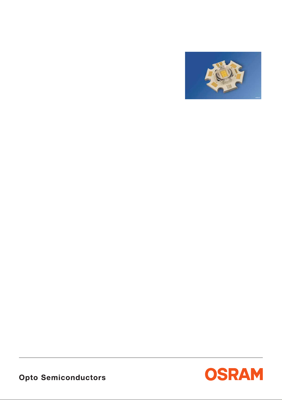
®
OSTAR
- Lighting with Optics
Lead (Pb) Free Product - RoHS Compliant
LE UW E3B
Besondere Merkmale
• Gehäusetyp: OSTAR® - Lighting
• Besonderheit des Bauteils: extrem hohe
Helligkeit und Leuchtdichte dank
Oberflächenemission und niedrigem
R
th
• Farbort: x = 0,31, y = 0,32 nach
CIE
1931 (weiß)
• typische Farbtemperatur: 6500 K
• Abstrahlwinkel: 130°
• Abstrahlende Fläche: 2,1 mm x 3,2 mm
• Technologie: ThInGaN
• Leuchtdichte: 22*10
• optischer Wirkungsgrad: 65 lm/W bei 350 mA
®
6
cd/m²
• Montierbarkeit: verschraubbar
Lötpads für Verdrahtung
• ESD-Festigkeit: ESD-sicher bis 2 kV nach
JESD22-A114-B
• Verpackungseinheit: pro Box 60 Stück
Anwendungen
• Strahler für die Allgemeinbeleuchtung
• Mikroskopbeleuchtung
• Verkehrszeichen
• Hochwertige Blitzlichter
Features
• package: OSTAR® - Lighting
• feature of the device: outstanding brightness
and luminance due to pure surface emission
and low R
th
• color coordinates: x = 0.31, y = 0.32 acc. to
CIE
1931 (white)
• typ. color temperature: 6500 K
• viewing angle: 130°
• light emitting surface: 2.1 mm x 3.2 mm
• technology: ThInGaN
®
• Luminance: 22*106 cd/m²
• optical efficiency: 65 lm/W at 350 mA
• mounting methods: screw holes
solder pads for wire attachment
• ESD-withstand voltage: up to 2 kV acc. to
JESD22-A114-B
method of packing: 60 pcs. per tray
Applications
• General lighting
• microscope illumination
• VMS (variable message signs)
• high end strobe light
2008-02-11 1
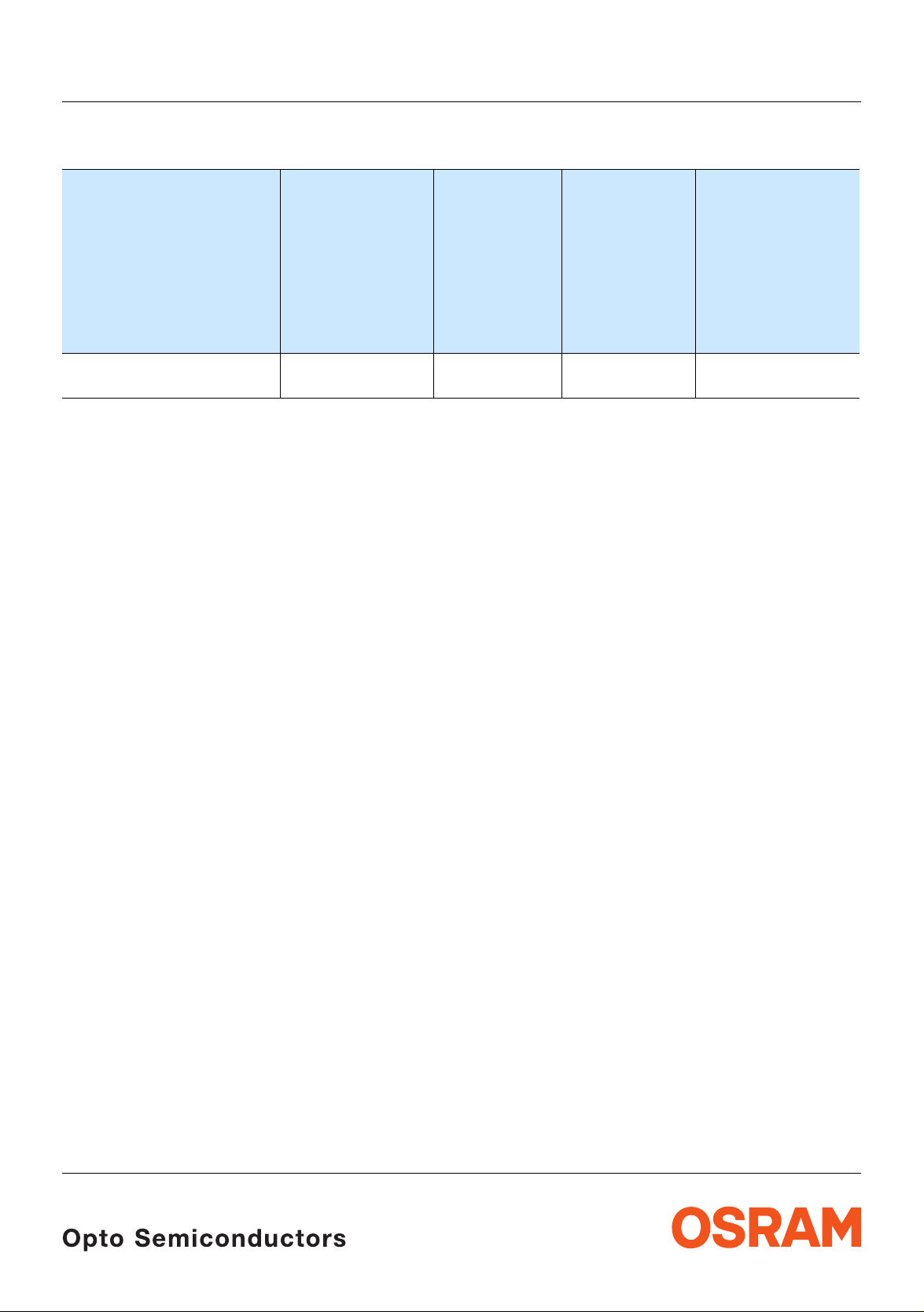
Bestellinformation Ordering Information
LE UW E3B
Typ
Type
LE UW E3B-PZQZ-4C8F
Anm.: Die oben genannten Typbezeichnungen umfassen die bestellbaren Selek tionen. Dies e bestehen aus wen igen
Helligkeitsgruppen (siehe
Verpackungseinheit geliefert. Z.B.: LE UW E3B-PZQZ-4C8F bedeutet, dass in der Verpackungseinheit nur
eine der Helligkeitsgruppen PZ, QX, QY oder QZ enthalten ist.
Um die Liefersicherheit zu gewährleisten, können einzelne Helligkeitsgruppen nicht bestellt werden.
Emissionsfarbe
Color of
Emission
white
(with 130° optics)
Seite 6 für nähere Informationen). Es wird nur eine einzige Helligkeitsgruppe pro
Lichtstrom
1) Seite 17
Luminous
Flux
1) page 17
I
= 700 mA
F
Φ
(lm)
V
Lichtstrom
2) Seite 17
Luminous
Intensity
2) page 17
I
= 700 mA
F
Ι
(cd)
V
Bestellnummer
Ordering Code
610 ... 1.120 830 (typ.) Q65110A7213
Gleiches gilt für die Farben, bei denen Farbortgruppen gemessen und gruppiert werden. Pro
Verpackungseinheit wird nur eine Farbortgruppe geliefert. Z.B.: LE
einer Verpackungseinheit nur eine der Farbortgruppen -4C bis -8F enthalten ist (siehe
Information).
Um die Liefersicherheit zu gewährleisten, können einzelne Farbortgruppen nicht bestellt werden.
UW E3B-PZQZ-4C8F bedeutet, dass in
Seite 5 für nähere
Note: The above Type Numbers represent the o rder groups which incl ude only a few b rightness g roups (se e page 6
for explanation). Only one group will be shipped in each packing unit (there will be no mixing of two groups in
each packing unit). E.g. LE
shippable for any one packing unit.
In order to ensure availability, single brightness groups will not be orderable.
UW E3B-PZQZ-4C8F means that only one group PZ, QX, QY or QZ will be
In a similar manner for colors where chromaticity coordinate groups are measured and binned, single
chromaticity coordinate groups will be shipped in any one packing unit . E.g. LE
that only 1 chromaticity coordinate group -4C to -8F will be shippable (see
In order to ensure availability, single chromaticity coordinate groups will not be orderable.
UW E3B-PZQZ-4C8F means
page 5 for explanation).
2008-02-11 2
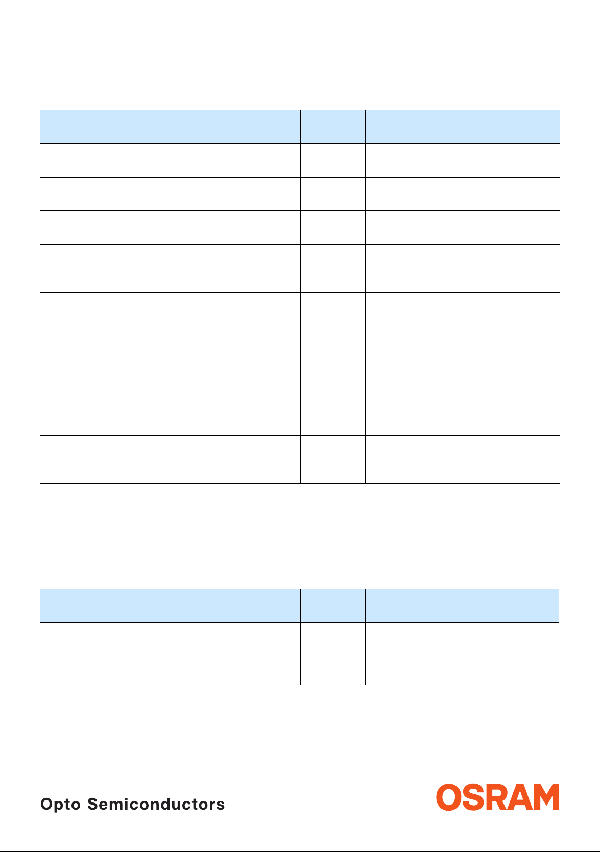
Grenzwerte Maximum Ratings
LE UW E3B
Bezeichnung
Parameter
Betriebstemperatur*
Operating temperature range*
Lagertemperatur
Storage temperature range
Sperrschichttemperatur
Junction temperature
minimaler Durchlassstr om pro Chip
minimum Forward current per chip
(T
board
=25°C)
maximaler Durchlassstrom pro Chip
maximum Forward current per chip
(T
board
=25°C)
Stoßstrom
Surge current
≤ 10 μs, D = 0.1, T
board
= 25 °C
Sperrspannung
Reverse voltage
(T
board
=25°C)
Leistungsaufnahme pro Modul
Power consumption per modul
(T
board
=25°C)
* Eine Betauung des Moduls muss vermieden werden.
Condensation on the module has to be avoided.
Symbol
Symbol
T
board, op
T
board, stg
T
j
I
F
I
F
I
FM
V
R
P
tot
Werte
Values
– 40 … + 100 °C
– 40 … + 100 °C
150 °C
100
1000
2000 mA
not designed for
reverse operation
27
Einheit
Unit
mA
mA
V
W
Kennwerte Charakteristics
Bezeichnung
Parameter
Wärmewiderstand des gesamten Moduls
Thermal resistance of the module
Sperrschicht / Bodenplatte
Junction / base plate
2008-02-11 3
Symbol
Symbol
R
th JB
Werte
Values
3
Einheit
Unit
K/W
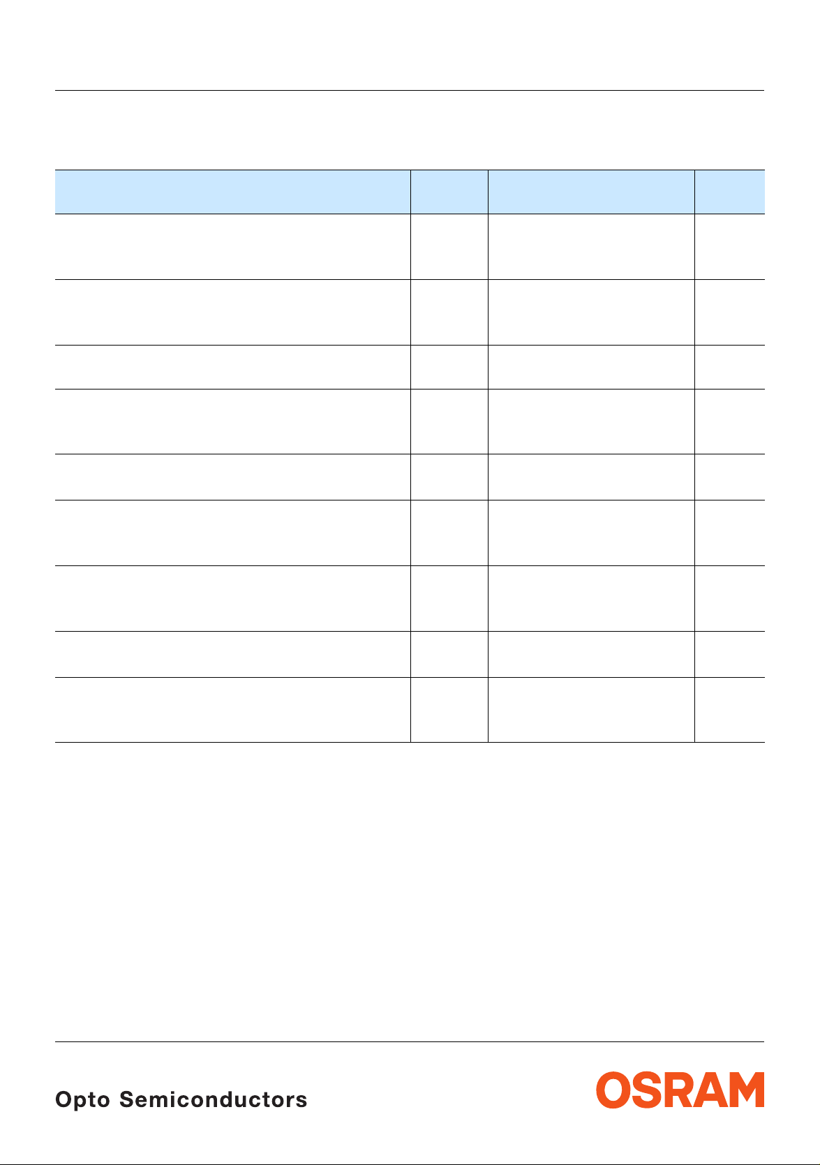
Kennwerte
Characteristics
(T
board
= 25 °C)
Bezeichnung
Parameter
3)
Farbkoordinate x nach CIE 1931
Chromaticity coordinate x acc. to CIE 1931
I
= 700 mA
F
Farbkoordinate y nach CIE 1931
Chromaticity coordinate y acc. to CIE 1931
I
= 700 mA
F
Abstrahlwinkel bei 50 %
Viewing angle at 50 % Ι
Durchlassspannung
Forward voltage
I
= 700 mA (max.)
F
4)
4) page 17
(Vollwinkel) (typ.)
Ι
V
V
)
Seite 17
Seite 17
3)
Seite 17
(typ.)
3) page 17
(typ.)
3) page 17
(min.)
(typ.)
Sperrstrom
Reverse current (max.)
Optischer Wirkungsgrad (typ.)
Optical efficiency (typ.)
I
= 700 mA
F
Optischer Wirkungsgrad (typ.)
Optical efficiency (typ.)
I
= 350 mA
F
Abstrahlende Fläche (typ.)
Radiating Surface
Leuchtdichte (typ.)
Luminance (typ.)
I
= 700 mA
F
LE UW E3B
Symbol
Symbol
Werte
Values
x 0.31 –
y 0.32 –
2
ϕ
130 Grad
2ϕ
V
V
V
I
η
η
η
η
A
L
L
F
F
F
R
opt
opt
opt
opt
Chip
V
V
reverse operation
17.4
20.8
24.5
not designed for
50 lm/W
65 lm/W
2.1 x 3.2 mm²
6
22*10
Einheit
Unit
deg.
V
V
V
μA
lm/W
lm/W
cd/m²
cd/m²
2008-02-11 4
LE UW E3B
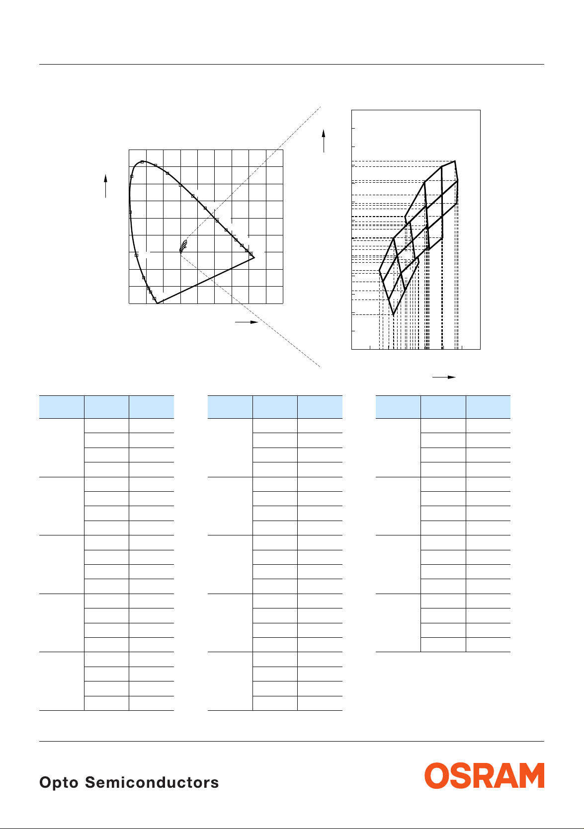
Farbortgruppen
3) Seite 17
Chromaticity coordinate groups
3) page 17
0.40
Cy
0.39
0.38
0.37
0.36
0.35
0.34
0.33
0.32
0.31
0.30
0.29
4e
4d
5e 6d
5d
5c
4c
6e
8f
7f
8e
6f
7e
7d
+
Cy
0.9
520
0.8
0.7
0.6
0.5
0.4
0.3
0.2
0.1
0
530
510
500
540
550
560
570
580
590
E
490
480
470
460
450
0.1 0.2 0.3 0.4 0.5 0.6 0.7 0.8 0.9
0
600
610
620
630
Cx
0.28
0.27
0.28
0.29
0.30
0.31
0.33
0.34
0.32
Cx
OHA03487
Gruppe
Group
4C 0.303 0.289 4D 0.300 0.297 4E 0.297 0.307
5C 0.309 0.302 5D 0.307 0.311 5E 0.305 0.321
6D 0.315 0.319 6E 0.313 0.329 6F 0.310 0.338
7D 0.322 0.324 7E 0.321 0.335 7F 0.321 0.346
8E 0.329 0.342 8F 0.329 0.354
Cx Cy Gruppe
Group
0.300 0.297 0.297 0.307 0.295 0.313
0.307 0.311 0.305 0.321 0.303 0.330
0.309 0.302 0.307 0.311 0.305 0.321
0.307 0.311 0.305 0.321 0.303 0.330
0.316 0.320 0.313 0.329 0.312 0.339
0.317 0.317 0.315 0.319 0.313 0.329
0.313 0.329 0.312 0.339 0.309 0.342
0.321 0.337 0.321 0.348 0.320 0.361
0.322 0.326 0.321 0.337 0.321 0.348
0.321 0.335 0.321 0.346 0.320 0.361
0.329 0.342 0.329 0.354 0.329 0.369
0.329 0.331 0.329 0.342 0.329 0.354
0.329 0.354 0.329 0.369
0.338 0.362 0.336 0.372
0.337 0.349 0.338 0.362
Cx Cy Gruppe
Group
Cx Cy
0.35
2008-02-11 5
LE UW E3B
Helligkeits-Gruppierungsschema Brightness Groups
Helligkeitsgruppe
Brightness Group
Lichtstrom
Luminous Flux
Φ
(lm)
V
PZ
QX
QY
QZ
Anm.: Die Standardlieferform von Serientypen beinhaltet eine Familiengruppe. Diese besteht aus wenigen Helligkeitsgruppen.
Note: The standard shipping format for serial types includes a family group of only a few individual brightness groups. Individual
Einzelne Helligkeitsgruppen sind nicht bestellbar.
brightness groups cannot be ordered.
2) Seite 17
610 ... 7 10
710 ... 8 20
820 ... 9 70
970 ... 1120
2) page 17
Gruppenbezeichnung auf Etikett
Group Name on Label
Beispiel: QY-4C
Example: QY-4C
Helligkeitsgruppe
Brightness Group
Wellenlänge
Wavelength
QY 4C
Anm.: In einer Verpackungseinheit ist immer nur eine Gruppe für jede Selektion enthalten.
Note: No packing unit ever contains more than one group for each selection.
2008-02-11 6
2)
Seite 17
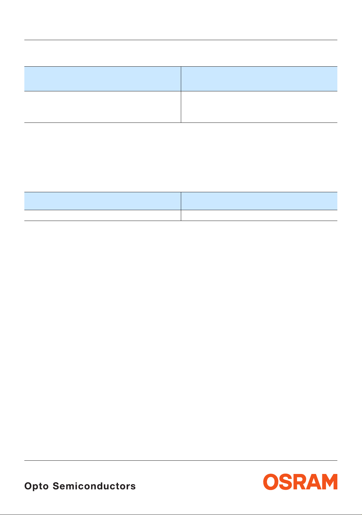
Relative spektrale Emission pro Chip
Relative Spectral Emission per Chip
2) page 17
V(λ) = spektrale Augenempfindlichkeit / Standard eye response curve
Φ
= f (λ), T
rel
Φ
100
rel
= 25 °C, IF = 700 mA
board
%
80
60
40
20
V
λ
LE UW E3B
OHL13926
0
400
Abstrahlcharakteristik (mit Optik)2)
450
Seite 17
Radiation Characteristic (with optics)
Ι
= f (ϕ); T
rel
50˚
60˚
70˚
80˚
90˚
board
= 25 °C
2) page 17
ϕ
550500 650600 750700 nm
λ
0˚10˚20˚30˚40˚
1.0
0.8
0.6
0.4
0.2
0
OHL03480
100˚
2008-02-11 7
0˚ 20˚ 40˚ 60˚ 80˚ 100˚ 120˚0.40.60.81.0
LE UW E3B
2)
Seite 17
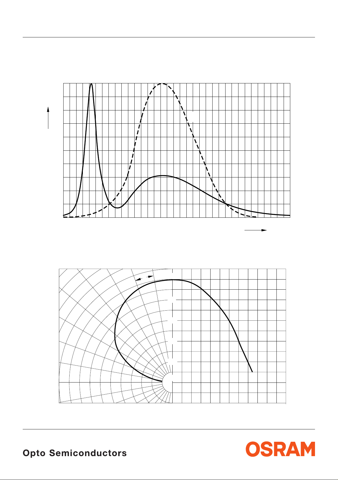
Durchlassstrom
Forward Current
I
= f (VF); T
F
10
board
3
2) page 17
= 25 °C
mA
I
F
5
2
10
5
1
10
15
2)
Seite 17
Farbortverschiebung
Chromaticity Coordinate Shift
x, y = f (IF); T
0.05
board
= 25 °C
OHL02857
V
F
2) page 17
OHL02806
V16 17 18 19 20 21 22 23 25
2) 5)
Relative Lichtfluss
Seite 17
Relative Luminous Flux
Φ
V/ΦV(700 mA)
Φ
Φ
V (700 mA)
V
10
10
2
0
5
-1
= f (IF); T
1
10
board
2) 5) page 17
= 25 °C
2
10
OHL02688
10
mA5
I
F
3
Cx,Δ CyΔ
0.03
Cy
0.02
0.01
Cx
0
-0.01
-0.02
0
200 400 600 800 1200
mA
I
F
2008-02-11 8

LE UW E3B
Relative Vorwärtsspannung
Relative Forward Voltage
ΔVF = VF - V
= f(Tj); IF= 700 mA
(25 °C)
F
2)
2) page 17
2.4
V
V
Δ
F
1.2
0.6
0
-0.6
-1.2
-1.8
Farbortverschiebung
-20 0 20 40
-40
2)
Seite 17
Chromaticity Coordinate Shift
x, y = f (T
); IF = 700 mA
j
0.008
Seite 17
OHL03505
2) page 17
˚C60 100-60
T
j
OHL03444
2)
Relative Lichtstrom
Seite 17
Relative Luminous Flux
Φ
V/ΦV(25 °C)
Φ
= f (Tj); IF = 700 mA
1.4
Φ
V
V (25 ˚C)
1.0
0.8
0.6
0.4
0.2
-600-40 -20 0 20
2) page 17
OHL12725
˚C6040
100
T
j
Cx,Δ CyΔ
Cy
0.002
Cx
0
-0.002
-0.004
-0.006
-0.008
-0.010
-0.012
-0.014
-0.016
-0.018
-60
-20 20 60 100 140
-40 0 40 80
˚C
T
j
2008-02-11 9

LE UW E3B
Maximal zulässiger Durchlassstrom
Max. Permissible Forward Current
I
= f (T)
F
t
P
OHL03414
OHL03420
T
1200
mA
I
F
800
600
400
200
0
0˚C
20 40 60 80 100
Zulässige Impulsbelastbarkeit IF = f (tp)
Permissible Pulse Handling Capability
Duty cycle D = parameter,
T
= 55°C
board
2.2
A
I
F
2.0
t
P
=
D
T
T
Board
Zulässige Impulsbelastbarkeit IF = f (tp)
Permissible Pulse Handling Capability
Duty cycle D = parameter,
T
= 100°C
board
2.2
I
F
A
I
F
t
P
=
D
T
1.8
t
P
OHL03421
T
I
F
1.8
D
=
0.005
1.6
0.01
0.02
0.05
1.4
0.1
0.2
0.5
1.2
1
1.0
0.8
1010 10
-2-3-4-5
1010
10
10 s10
210-1
t
p
2008-02-11 10
1.6
1.4
1.2
1.0
0.8
0.6
0.4
0.2
D
=
0.005
0.01
0.02
0.05
0.1
0.2
0.5
1
0
1010 10
-2-3-4-5
1010
10
10 s10
210-1
t
p
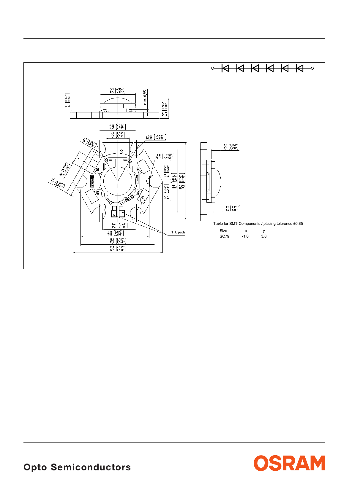
Maßzeichnung
6)
Package Outlines
Seite 17
6) page 17
LE UW E3B
PinPin
OHEE2882
2008-02-11 11

LE UW E3B
Bestimmung der Bord - Temperatur T
B
Die Board - Temperatur TB kann mit Hilfe eines NTC bestimmt werden, gemessen an den NTC
Anschlusskontakten. Aus T
Estimation of the Bord Temperature T
kann TB folgendermaßen berechnet werden.
NTC
B
The board temperature TB can be determined with the NTC, measured on the NTC pads. TB can be
calculated using T
TB = T
R
th, B-NTC
P
OSTAR
+ R
NTC
= 0,25 K/
= IF x U
th, B-NTC
F
as shown below.
NTC
x P
OSTAR
W
Montage-Hinweis Mounting Note
Allgemein: Abhängig von der Schutzklasse der späteren Leuchte ist eine
Befestigungsmethode auszuwählen, mit welcher die vorgeschrieb enen Normen
(IEC 60598-1) der Beleuchtungstechnik eingehalten werden.
Siehe auch Applikationsschrift „Mounting Guideline for High Power Light
®
Sources of the OSTAR
LED Product family“.
General: Dependent on the safety class of the final lamp a mounting method should be
chosen in order to fulfil the standards for lighting technology (IEC 60598-1)
See application note „Mounting Guideline for High Power Light Sources of the
®
OSTAR
LED Product family“.
Anschlusskontaktierung Contacting
Drahttyp
Wire type
AWG 18 ~0.8 mm (Litze; flexible wire) 3.2 mm (Meisel; Chisel) 250 °C
AWG 20 ~0.5 mm (Litze; flexible wire) 3.2 mm (Meisel; Chisel) 250 °C
AWG 22 ~0.3 mm (Litze; flexible wire) 3.2 mm (Meisel; Chisel) 250 °C
2008-02-11 12
Durchmesser
Diameter
Lötspitze
Solder Tip
Temperatur
Temperature
350 °C
350 °C
350 °C
Lötzeit
Solder Time
16 sec.
6 sec
14 sec.
5 sec
9 sec.
3 sec

LE UW E3B
Empfehlung für Einbau in
Recommendation for
Leuchte der Schutzklasse
Class I Luminaire
Leuchte der Schutzklasse II
Class II Luminaire
Leuchte der Schutzklasse III
Class III Luminaire
Symbol Schutzklasse
Symbol safety class
Befestigung
Fixation
nach IEC-Norm (z.B. Klammern,
Kleben)
according IEC standard (e.g. Clamps,
Adhesive
nach IEC-Norm (Klammern, Kleben)
according IEC standard (e.g. Clamps,
Adhesive)
M3 Schrauben mit max. Drehmoment 0.8Nm;
typischer Anpressdruck im Bereich von
0.35MPa; die Verwendung von mind. 3
Schrauben, jeweils um 120° versetzt und eine
Schraubensicherung wird empfohlen
M3 screws with a maximum torque of 0.8 Nm;
typical contact pressure in the range of 0.35
MPa; at lease 3 screws, alignment 120° and
screw locking is recommended
2008-02-11 13

6)
Verpackung / Polarität und Lage
Seite 17
Method of Packing / Polarity and Orientation
6) page 17
LE UW E3B
DeviceTray label
±1 (0.039)
160 (6.299)
30.98 (1.220) 30.98 (1.220)
Barcode-Tray-Etikett (BTL) Barcode-Tray-Label (BTL)
Data
Matrix
Code
BIN
BIn Nr.
210 (8.268)
LE xxx xxx
MATERIAL:
8.9 (0.350)
±1 (0.039)
Group:
xxxx-xxxx-xxxx Date Code
Bar Code
Material Number Batch Batch Number
OHOY2897
DC:
OHA02684
2008-02-11 14
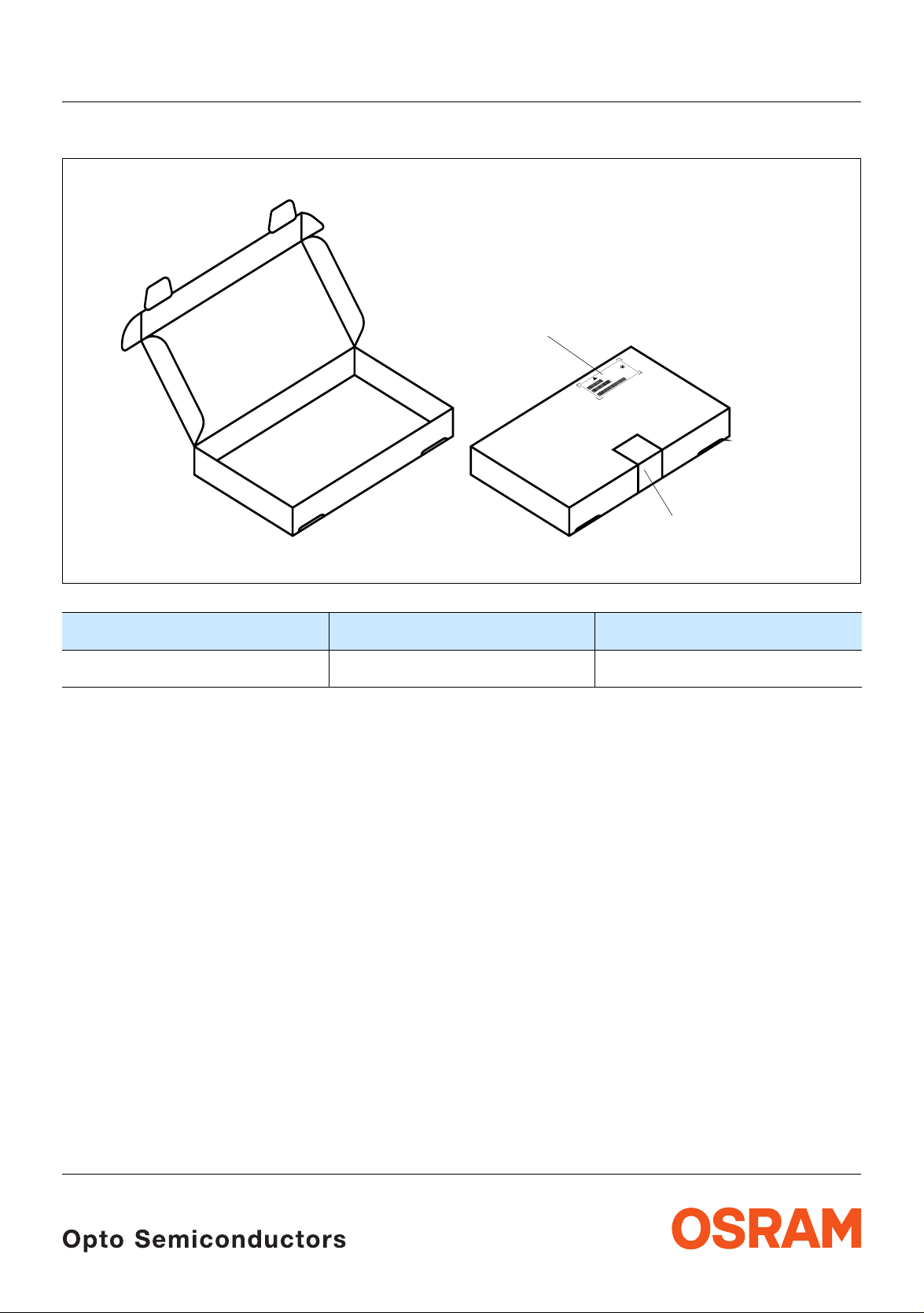
Kartonverpackung und Materialien
Transportation Packing and Materials
Box
Barcode label
LE UW E3B
0
2
0
1
2
-
-
P
1
-
:
1
Q
T
:
in
S
B
n2
:
p
i
3
R
B
m
n
Y
i
C
6
e
R
M
B
T
T
7
0
C
E
2
6
R
T
D
2
L
D
0
T
C
X
4
M
E
2
E
0
L
Y
6
2
T
l
2
8
P
S
a
a
2
1
L
n
O
1
o
i
R
-
3
T
it
:
i
d
Q
R
t
d
l
7
A
+
A
7
V
u
1
0
-
K
R
M
C
P
A
:
P
P
U
O
R
G
)
G
(
4
4
1
8
o
0
t
9
:
s
C
9
p
r
/
1
o
D
t
)
2
O
c
D
0
9
u
M
0
(
d
0
1
A
n
0
2
o
:
0
4
c
O
2
3
i
SR
:
N
2
Y
m
O
1
H
T
e
C
H
Q
S
T
)
A
G
Q
(
B
3
)
2
P
1
6
:
(
O
245
N
T
1
Muster
O
L
0
)
0
T
1
11
(
:
O
N
D
O
R
P
)
X
(
Original packing label
OHA02886
Dimensions of transportati on bo x in mm (inch)
Breite / Width Länge / length Höhe / height
223 ±5 (8,7795 ±0,19685) 170 ±5 (6,6929 ±0,19685) 21 ±5 (0,826772 ±0,19685)
Die Bewertung der Augesicherheit erfolgt nach dem Standard CIE S009/E:2002 ("photobiological safety of lamps and
lamp systems")
Im Risikogruppensystem dieser CIE- Norm erfüllen die in diesem Datenblatt angegebenen LED die "low ris k"- Gruppe
(die die sich im "sichtbaren" Spektralbereich auf eine Expositionsdauer von 100 s bezieht). Unter realen Umständen
(für Expositionsdauer, Augenpupille, Betrachtungsabstand) geht damit von diesen Bauelementen keinerlei
Augengefährdung aus.
Grundsätzlich sollte jedoch erwähnt werden, dass intensive Lichtquellen durch ihre Blendwirkung ein hohes
sekundäres Gefahrenpotenzial besitzen. Wie nach d em Blick in andere helle Lichtquellen (z.B. Au toscheinwerfer) auch,
können temporär eingeschränktes Sehvermögen und Nachbilder je nach Situation zu Irritationen, Belästigungen,
Beeinträchtigungen oder sogar Unfällen führen.
The evaluation of eye safety occurs according to the standard CIE S009/E:2002 ("photobiological safety of lamps and
lamp systems").
Within the risk grouping system of this CIE standard, the LEDs specified in this data sheet fall into th e "low risk" group
(relating to devices in the visible spectrum with an exposure time of 100 s). Under real circumstances (for exposure
time, eye pupils, observation distance), it is assumed that no endangermen t to the eye exists from these devices.
As a matter of principle, however, it should be mentioned that intense light sources have a high secondary exposure
potential due to their blinding effect. As is also true when viewing other bright light sources (e.g. headlights), temporary
reduction in visual acuity and afterimages can occur, leading to irritation, annoyance, visual impairment, and even
accidents, depending on the situation.
.
2008-02-11 15
LE UW E3B
Revision History: 2008-02-11
Previous Version: 2007-09-26
Page Subjects (major changes since last revision) Date of change
12
comment „app note“ added
2008-02-11
Attention please!
The information describes the type of component and shall not be considered as assured characteristics.
Terms of delivery and rights to change design reserved. Due to technical requirements components may contain
dangerous substances. For information on the types in question please contact our Sales Organization.
If printed or downloaded, please find the latest version in the Internet.
Packing
Please use the recycling operators known to you. We can also help you – get in touch with your nearest sales office.
By agreement we will take packing material back, if it is sorted. You must bear the costs of transport. For packing
material that is returned to us unsorted or wh ich we are not obliged to accept, we shall hav e to invoice you for any costs
incurred.
Components used in life-support devices or systems must be expressly authorized for such purpose! Critical
components
OSRAM OS.
2008-02-11 16
7) page 17
may only be used in life-support devices or systems
8) page 17
with the express written approval of
LE UW E3B
Fußnoten:
1)
Helligkeitswerte werden mit einer
Stromeinprägedauer von 25
Genauigkeit von ±
Lichtstärkemessung nach CIE127 Condition A.
2)
Wegen der besonderen Prozessbedingungen bei der
11% ermittelt. Messbedingung für
ms und einer
Herstellung von LED können typische oder abgeleitete
technische Parameter nur aufgrund statistischer
Werte wiedergegeben werden. Diese stimmen nicht
notwendigerweise mit den Werten jedes einzelnen
Produktes überein, dessen Werte sich von typischen
und abgeleiteten Werten oder typischen Kennlinien
unterscheiden können. Falls erforderlich, z.B.
aufgrund technischer Verbesserungen, werden diese
typischen Werte ohne weitere Ankündigung geändert.
3)
Farbortgruppen werden mit einer Stromeinprägedauer
von 25
4)
5)
ms und einer Genauigkeit von ±0,01 ermittelt.
Spannungswerte werden mit einer
Stromeinprägedauer von 1
von ±0,5
V ermittelt.
ms und einer Genauigkeit
Im gestrichelten Bereich der Kennlinien muss mit
erhöhten Helligkeitsunterschieden zwischen
Leuchtdioden innerhalb einer Verpackungseinheit
gerechnet werden.
6)
Maße werden wie folgt angegeben: mm (inch).
7)
Ein kritisches Bauteil ist ein Bauteil, das in
lebenserhaltenden Apparaten oder Systemen
eingesetzt wird und dessen Defekt voraussichtlich zu
einer Fehlfunktion dieses lebenserhaltenden
Apparates oder Systems führen wird oder die
Sicherheit oder Effektivität dieses Apparates oder
Systems beeinträchtigt.
8)
Lebenserhaltende Apparate oder Systeme sind für (a)
die Implantierung in den menschlichen Körper
oder
(b) für die Lebenserhaltung bestimmt.
Falls sie versagen, kann davon ausgega ngen werden,
dass die Gesundheit und das Leben des Patienten in
Gefahr ist.
Published by
OSRAM Opto Semiconductors GmbH
Leibnizstrasse 4, D-93055 Regensburg
www.osram-os.com
© All Rights Reserved.
Remarks:
1)
Brightness groups are tested at a current pulse
duration of 25
ms and a tolerance of ± 11%. Condition
for luminous intensity measurement acc. to CIE127
condition A
2)
Due to the special conditions of the manufacturing
processes of LED, the typical data or calculated
correlations of technical parameters can only reflect
statistical figures. These do not necessarily
correspond to the actual parameters of each single
product, which could differ from the typical data and
calculated correlations or the typical characeristic line.
If requested, e.g. because of technical improvements,
these typ. data will be changed without any further
notice.
3)
Chromaticity coordinate groups are tested at a current
pulse duration of 25
4)
Forward voltages are tested at a current pulse
duration of 1
5)
In the range where the line of the graph is broken , you
ms and a tolerance of ±0.5 V.
ms and a tolerance of ±0.01.
must expect higher brightness differences between
single LEDs within one packing unit.
6)
Dimensions are specified as follows: mm (inch).
7)
A critical component is a component used in a
life-support device or system whose failure can
reasonably be expected to cause the failure of that
life-support device or system, or to affect its safety or
the effectiveness of that device or system.
8)
Life support devices or systems are intended
(a) to be implanted in the human body,
or
(b) to support and/or maintain and sustain human life.
If they fail, it is reasonable to assume that the health
and the life of the user may be endangered.
2008-02-11 17
 Loading...