

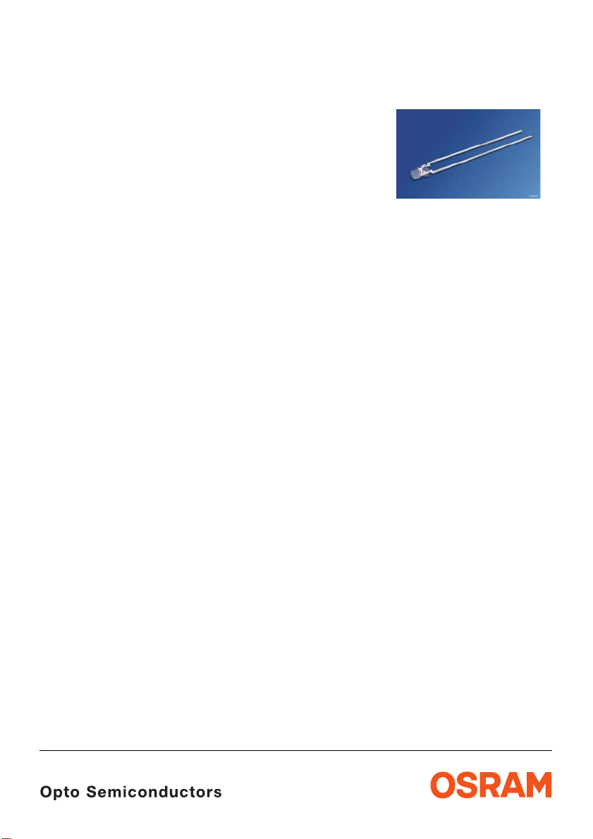
Hyper 3 mm (T1) LED, micro Diffused
Hyper-Bright LED
Lead (Pb) Free Product - RoHS Compliant
LB 3333, LT 3333
Vorläufige Daten für OS-PCN-2005-030-A /
Preliminary Data for OS-PCN-2005-030-A
Besondere Merkmale
• Gehäusetyp: nicht eingefärbtes, minimal
diffuses 3
• Besonderheit des Bauteils: enge
Abstrahlcharakteristik; Lötspieße mit
Aufsetzebene
• Wellenlänge: 470 nm (blau),
528
• Abstrahlwinkel: 30°
• Technologie: InGaN
• optischer Wirkungsgrad: 2 lm/W (blau),
8
• Gruppierungsparameter: Lichtstärke,
Wellenlänge
• Lötmethode: Wellenlöten (TTW)
• Verpackung: Schüttgut, gegurtet lieferbar
• ESD-Festigkeit: ESD-sicher bis 2 kV nach
JESD22-A114-B
Anwendungen
• Informationsanzeigen im Außenbereich
• optischer Indikator
• Signal- und Symbolleuchten
• Markierungsbeleuchtung (z.B. Stufen,
Fluchtwege, u.ä.)
mm (T1) Gehäuse
nm (true green)
lm/W (true green)
Features
• package: colorless, micro diffused 3 mm (T1)
package
• feature of the device: narrow viewing angle,
solder leads with stand-off
• wavelength: 470 nm (blue),
528
nm (true green)
• viewing angle: 30°
• technology: InGaN
• optical efficiency: 2 lm/W (blue),
8
lm/W (true green)
• grouping parameter: luminous intensity,
wavelength
• soldering methods: TTW soldering
• packing: bulk, available taped on reel
• ESD-withstand voltage: up to 2 kV acc. to
JESD22-A114-B
Applications
• outdoor displays
• optical indicators
• signal and symbol luminaire
• marker lights (e.g. steps, exit ways, etc.)
2006-04-04 1

LB 3333, LT 3333
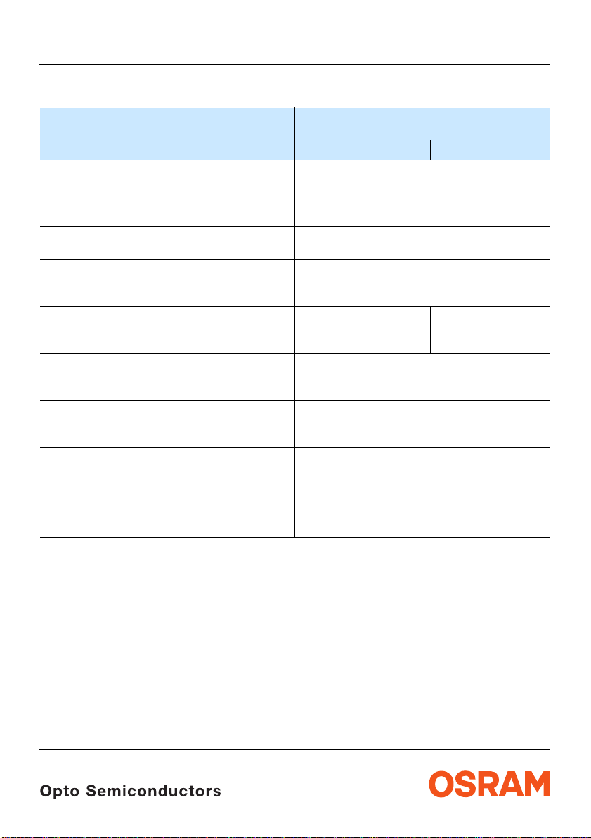
Bestellinformation Ordering Information
Typ
Type
LB 3333-Q1R2-35
LB 3333-R1S2-35
LB 3333-Q1S2-35
LT 3333-T1U2-35
LT 3333-U1V2-35
LT 3333-S2V2-35
Anm.: Die oben genannten Typbezeichnungen umfassen die bestellbaren Selekti onen. Diese be stehen aus weni gen
Helligkeitsgruppen (siehe
Gurt geliefert. Z.B.: LB 3333-Q1R2-35 bedeutet, dass auf dem Gurt nur eine der Helligkeitsgruppen Q1, Q2,
R1 oder R2 enthalten ist.
Um die Liefersicherheit zu gewährleisten, können einzelne Helligkeitsgruppen nicht bestellt werden.
Gleiches gilt für die Farben, bei denen Wellenlängengruppen gemessen und gruppiert werden. Pro Gurt wird
nur eine Wellenlängengruppe geliefert. Z.B.: LB
Wellenlängengruppen -3, -4, oder -5 enthalten ist (siehe
Um die Liefersicherheit zu gewährleisten, können einzelne Wellenlängengruppen nicht bestellt werden.
Emissionsfarbe
Color of
Emission
Gehäusefarbe
Color of
Package
Lichtstärke
Seite 13
Luminous
Intensity
page 13
I
= 10 mA
F
I
(mcd)
V
blue colorless clear 71 ... 180
112 ... 280
71 ... 280
true green colorless clear 280 ... 710
450 ... 1120
224 ... 1120
Seite 5 für nähere Informationen). Es wird nur eine einzige Helligkeitsgruppe pro
3333-Q1R2-35 bedeutet, dass auf dem Gurt nur eine der
Seite 5 für nähere Information).
1)
Lichtstrom
Seite 13
Luminous
1)
Flux
page 13
I
= 10 mA
F
Φ
(mlm)
V
120 (typ.)
195 (typ.)
170 (typ.)
500 (typ.)
780 (typ.)
680 (typ.)
2)
Bestellnummer
2)
Ordering Code
Q65110A2793
Q65110A2964
Q65110A2794
on request
on request
on request
Note: The above Type Numbers represent the order groups which include only a few brightness groups (see page 5
for explanation). Only one group will be shipped on each reel (there will be no mixing of two groups on each
reel). E.g. LB
In order to ensure availability, single brightness groups will not be orderable.
In a similar manner for colors where wavelength groups are measured and binned, single wavelength groups
will be shipped on any one reel. E.g. LB
be shippable. In order to ensure availability, single wavelength groups will not be orderable (see
explanation).
2006-04-04 2
3333-Q1R2-35 means that only one group Q1, Q2, R1 or R2 will be shippable for any one reel.
3333-Q1R2-35 means that only 1 wavelength group -3, -4, or -5 will
page 5 for
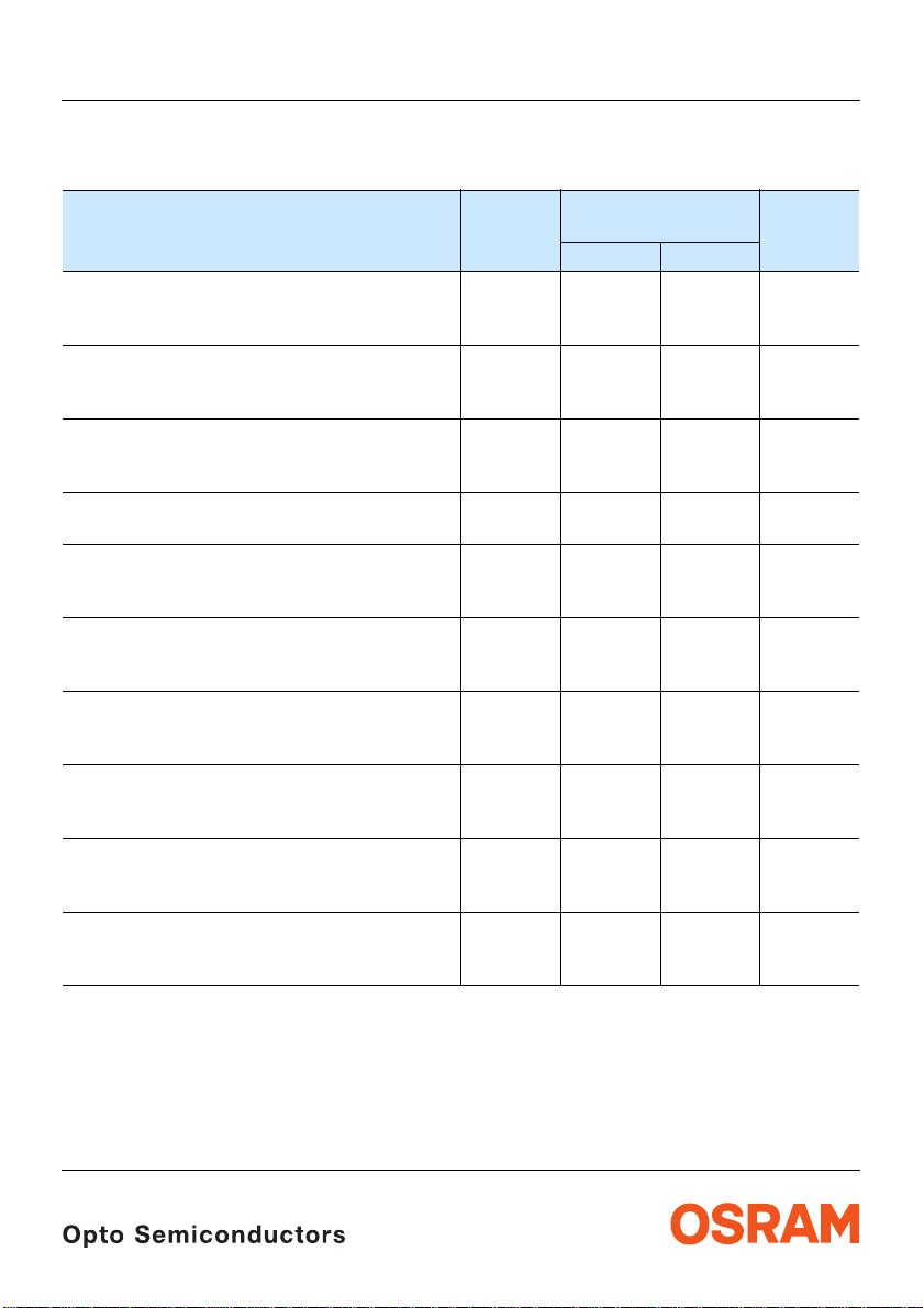
Grenzwerte Maximum Ratings
Bezeichnung
Parameter
Betriebstemperatur
Operating temperature range
Lagertemperatur
Storage temperature range
Sperrschichttemperatur
Junction temperature
Durchlassstrom
Forward current
(TA=25°C)
Stoßstrom
Surge current
t ≤ 10 µs, D = 0.005, T
Sperrspannung
Reverse voltage
3) Seite 13
3) page 13
=25°C
A
(TA=25°C)
Leistungsaufnahme
Power consumption
(TA=25°C)
Wärmewiderstand
Thermal resistance
Sperrschicht/Umgebung
Junction/ambient
4) Seite 13
4) page 13
5) Seite 13
5) page 13
Sperrschicht/Lötpad
Junction/solder point
Symbol
Symbol
T
op
T
stg
T
j
I
F
I
FM
V
R
P
tot
R
th JA
R
th JS
LB 3333, LT 3333
Werte
Values
LB LT
– 55 … + 100 °C
– 55 … + 100 °C
+ 100 °C
20 mA
200 250 mA
5 V
80 mW
400
180
Einheit
Unit
K/W
K/W
2006-04-04 3
Kennwerte
Characteristics
(TA = 25 °C)
Bezeichnung
Parameter
Wellenlänge des emittierten Lichtes (typ.)
Wavelength at peak emission
I
= 10 mA
F
Dominantwellenlänge
Dominant wavelength
I
= 10 mA (max.)
F
Spektrale Bandbreite bei 50 % I
Spectral bandwidth at 50 % I
I
= 10 mA
F
6) Seite 13
6) page 13
rel max
rel max
(min.)
(typ.)
(typ.)
Abstrahlwinkel bei 50 % IV (Vollwinkel) (typ.)
Viewing angle at 50 % I
Durchlassspannung
Forward voltage
I
= 10 mA (max.)
F
7) Seite 13
7) page 13
V
(min.)
(typ.)
Sperrstrom (typ.)
Reverse current (max.)
V
= 5 V
R
Temperaturkoeffizient von λ
Temperature coefficient of λ
I
= 10 mA; –10°C ≤ T ≤ 100°C
F
Temperaturkoeffizient von λ
Temperature coefficient of λ
I
= 10 mA; –10°C ≤ T ≤ 100°C
F
Temperaturkoeffizient von V
Temperature coefficient of V
I
= 10 mA; –10°C ≤ T ≤ 100°C
F
peak
peak
dom
dom
F
F
(typ.)
(typ.)
(typ.)
Optischer Wirkungsgrad (typ.)
Optical efficiency
I
= 10 mA
F
* Einzelgruppen siehe Seite 5
Individual groups on page 5
LB 3333, LT 3333
Symbol
Symbol
λ
peak
λ
dom
λ
dom
λ
dom
∆λ
2ϕ 30 30 Grad
V
F
V
F
V
F
I
R
I
R
TC
λpeak
TC
λdom
TC
V
η
opt
Werte
Values
LB LT
465 523 nm
465
471*
477
523
532*
541
25 33 nm
2.7
3.1
3.7
0.01
10
2.7
3.0
3.7
0.01
10
0.04 0.04 nm/K
0.03 0.04 nm/K
– 4.5 – 3.6 mV/K
2 8 lm/W
Einheit
Unit
nm
nm
nm
deg.
V
V
V
µA
µA
2006-04-04 4

LB 3333, LT 3333
6) Seite 13
Wellenlängengruppen (Dominantwellenlänge)
Wavelength Groups (Dominant Wavelength)
Gruppe
Group
min. max. min. max.
blue true green Einheit
6) page 13
3 465 469 523 529 nm
4 469 473 529 535 nm
5 473 477 535 541 nm
Helligkeits-Gruppierungsschema Brightness Groups
Helligkeitsgruppe
Brightness Group
Q1
Q2
R1
R2
S1
S2
T1
T2
U1
U2
V1
V2
Anm.: Die Standardlieferform von Serientypen beinhaltet entweder eine untere Familiengruppe, eine obere
Familiengruppe oder eine Sammelgruppe, die aus nur wengen
Einzelne Helligkeitsgruppen können nicht bestellt werden.
Note: The standard shipping format for serial types includes either a lower familiy group, an upper family group or
a grouping of all individual groups of only a few
Individual brightness groups cannot be ordered.
Lichtstärke
Luminous Intensity
I
(mcd)
V
71 ... 90
90 ... 112
112 ... 140
140 ... 180
180 ... 224
224 ... 280
280 ... 355
355 ... 450
450 ... 560
560 ... 710
710 ... 900
900 ... 1120
1) Seite 13
1) page 13
Helligkeitsgruppen bestehen.
individual brightness groups.
Lichtstrom
2) Seite 13
Luminous Flux
Φ
(mlm)
V
80 (typ.)
105 (typ.)
130 (typ.)
165 (typ.)
205 (typ.)
260 (typ.)
320 (typ.)
410 (typ.)
510 (typ.)
640 (typ.)
810 (typ.)
1020 (typ.)
Unit
2) page 13
Gruppenbezeichnung auf Etikett
Group Name on Label
Beispiel: Q2-4
Example: Q2-4
Helligkeitsgruppe
Brightness Group
Wellenlängengruppen
Wavelength groups
Q2 4
Anm.: In einer Verpackungseinheit / Gurt ist immer nur eine Gruppe für jede Selektion enthalten.
Note: No packing unit / tape ever contains more than one group for each selection.
2006-04-04 5

LB 3333, LT 3333
Relative spektrale Emission
Relative Spectral Emission
2) Seite 13
2) page 13
V(λ) = spektrale Augenempfindlichkeit / Standard eye response curve
I
= f (λ), TA = 25 °C, IF = 10 mA
rel
100
%
I
rel
80
V
λ
60
40
blue
true green
20
0
400
Abstrahlcharakteristik
Radiation Characteristic
I
= f (ϕ); TA = 25 °C
rel
2) Seite 13
2) page 13
550450 500 600
0˚10˚20˚30˚40˚
ϕ
1.0
50˚
0.8
OHL00478
650 nmλ700
OHL00733
60˚
70˚
80˚
90˚
100˚
2006-04-04 6
0.6
0.4
0.2
0
0˚ 20˚ 40˚ 60˚ 80˚ 100˚ 120˚0.40.60.81.0

LB 3333, LT 3333
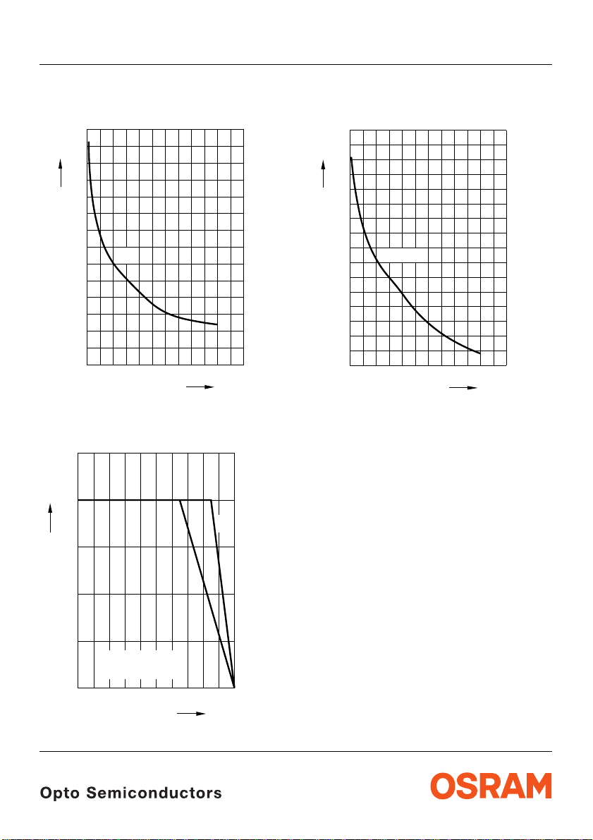
Durchlassstrom
Forward Current
I
= f (VF); TA = 25 °C
F
2
10
mA
I
F
5
1
10
5
0
10
5
-1
10
2.0
2.5 3.0 3.5 4.0 4.5 5.0
2) Seite 13
2) page 13
blue
true green
OHL00485
V
V
F
Relative Lichtstärke
2) 8) Seite 13
Relative Luminous Intensity
I
V/IV(10 mA)
= f (IF); TA = 25 °C
1
10
I
V
I
(10 mA)
V
5
0
10
5
-1
10
10
Relative Lichtstärke
10
5
2) Seite 13
Relative Luminous Intensity
I
= f (Tj); IF = 10 mA
V/IV(25 °C)
1.4
I
V
I
V (25 ˚C)
1.2
2) 8) page 13
10
2) page 13
OHL10494
mA 10
I
F
OHL13637
2
2006-04-04 7
1.0
0.8
true green
0.6
blue
0.4
0.2
0
-60
-40 -20 0 20 40 60 100
˚C
T
j
LB 3333, LT 3333
Dominante Wellenlänge
Dominant Wavelength
LB; λ
= f (IF); TA = 25 °C
dom
474
nm
λ
dom
2) Seite 13
2) page 13
OHL10503
473
472
471
470
blue
469
468
467
0 mA
20 40 60 80 120
I
f
Maximal zulässiger Durchlassstrom
Max. Permissible Forward Current
I
= f (T)
F
25
OHL01859
mA
Dominante Wellenlänge
Dominant Wavelength
LT; λ
= f (IF); TA = 25 °C
dom
550
nm
λ
dom
540
535
530
true green
525
520
515
510
0 mA
20 40 60 80 120
2) Seite 13
2) page 13
OHL00882
I
f
I
F
20
T
T
A
S
15
10
5
temp. ambient
T
A
temp. solder point
T
S
0
40
200
˚C
1008060
T
2006-04-04 8

LB 3333, LT 3333
Zulässige Impulsbelastbarkeit IF = f (tp)
Permissible Pulse Handling Capability
Duty cycle D = parameter, TA= 25 °C
LB
0.25
A
I
F
D
=
0.15
0.10
0.05
0
-5
10
10-410-310-210-110010
t
P
T
t
P
D
=
0.005
0.01
0.02
0.05
0.1
0.2
0.5
1
OHL02015
T
I
F
1
2
10s
t
p
Zulässige Impulsbelastbarkeit IF = f (tp)
Permissible Pulse Handling Capability
Duty cycle D = parameter, TA= 25 °C
LT
OHL02017
t
P
t
P
T
I
F
T
I
0.30
F
A
D
=
Zulässige Impulsbelastbarkeit IF = f (tp)
Permissible Pulse Handling Capability
Duty cycle D = parameter, TA= 85 °C
LB
0.25
A
I
F
D
=
0.15
0.10
0.05
0
-5
10
10-410-310-210-110010
t
T
P
t
P
D
=
0.005
0.01
0.02
0.05
0.1
0.2
0.5
1
OHL02016
T
I
F
1
2
10s
t
p
Zulässige Impulsbelastbarkeit IF = f (tp)
Permissible Pulse Handling Capability
Duty cycle D = parameter, TA= 85 °C
LT
OHL02018
t
P
t
P
T
I
F
T
I
0.30
F
A
D
=
0.20
D
=
0.15
0.10
0.05
0
-5
10
10-410-310-210-110010
0.005
0.01
0.02
0.05
0.1
0.2
0.5
1
t
1
2
10s
p
2006-04-04 9
0.20
0.15
0.10
0.05
0
-5
10
10-410-310-210-110010
D
=
0.005
0.01
0.02
0.05
0.1
0.2
0.5
1
1
2
10s
t
p

LB 3333, LT 3333
Maßzeichnung
Package Outlines
9) Seite 13
9) page 13
spacing
2.54 (0.100)
Cathode
0.7 (0.028)
0.6 (0.024)
0.4 (0.016)
1.8 (0.071)
1.2 (0.047)
29.0 (1.142)
27.0 (1.063)
Area not flat
0.4 (0.016)
0.8 (0.031)
0.4 (0.016)
1.1 (0.043)
0.9 (0.035)
4.8 (0.189)
4.4 (0.173)
3.7 (0.146)
3.5 (0.138)
6.1 (0.240)
5.7 (0.224)
ø2.9 (0.114)
Kathodenkennung: kürzerer Lötspieß
Cathode mark: short solder lead
Gewicht / Approx. weight: 0.15 g
3.4 (0.134)
3.1 (0.122)
0.6 (0.024)
0.4 (0.016)
ø2.7 (0.106)
GEXY6045
Empfohlenes Lötpaddesign
Recommended Solder Pad
9) Seite 13
9) page 13
Wellenlöten (TTW)
TTW Soldering
4.8 (0.189)
4 (0.157)
2006-04-04 10
OHLPY985

Lötbedingungen
Soldering Conditions
Wellenlöten (TTW) (nach CECC 00802)
TTW Soldering (acc. to CECC 00802)
LB 3333, LT 3333
300
C
250
T
235 C
200
150
100
50
0
0
C... 260
1. Welle
1. wave
ca 200 K/s
CC... 130100
50 100 150 200 250
10 s
2 K/s
2. Welle
2. wave
5 K/s
Zwangskühlung
forced cooling
2 K/s
Normalkurve
standard curve
Grenzkurven
limit curves
t
OHLY0598
s
2006-04-04 11

LB 3333, LT 3333
Revision History: 2006-04-04
Previous Version: 2005-04-27
Page Subjects (major changes since last revision) Date of change
4 min./max. values for dominant wavelength 2004-11-04
5 brightness groups 2005-04-27
2; 5 brightness groups for true green acc. to OS-PCN-2005-030-A 2005-11-07
4 Forward voltage 2006-04-04
7 Forward Current 2006-04-04
Attention please!
The information describes the type of component and shall not be considered as assured characteristics.
Terms of delivery and rights to change design reserved. Due to technical requirements components may contain
dangerous substances. For information on the types in question please contact our Sale s Organization.
If printed or downloaded, please find the latest version in the Internet.
Packing
Please use the recycling operators known to you. We can also help you – get in touch with your nearest sales office.
By agreement we will take packing material back, if it is sorted. You must bear the costs of transport. For packing
material that is returned to us unsorted or which we are not obliged to accept, we shall have to invoice yo u for any costs
incurred.
Components used in life-support devices or systems must be expressly authorized for such purpose! Critical
components
OSRAM OS.
2006-04-04 12
10) page 13
may only be used in life-support devices or systems
11) page 13
with the express written approval of
LB 3333, LT 3333
Fußnoten:
1)
Helligkeitswerte werden mit einer
Stromeinprägedauer von 25
Genauigkeit von ±
2)
Wegen der besonderen Prozessbedingungen bei der
Herstellung von LED können typische oder abgeleitete
technische Parameter nur aufgrund statistischer
Werte wiedergegeben werden. Diese stimmen nicht
notwendigerweise mit den Werten jedes einzelnen
Produktes überein, dessen Werte sich von typischen
und abgeleiteten Werten oder typischen Kennlinien
unterscheiden können. Falls erforderlich, z.B.
aufgrund technischer Verbesserungen, werden diese
typischen Werte ohne weitere Ankündigung g eändert.
3)
Die LED kann kurzzeitig in Sperrichtung betrieben
werden.
4)
Rth erhöht sich um 13 K/W pro mm Beinchenlänge.
Minimale Beinchenlänge,
Entfernung vom Verguss ist 0 mm.
5)
R
ergibt sich bei Montage auf PC-Board FR 4
thJA
(Padgröße
Minimale Beinchenlänge,
Entfernung vom Verguss ist 0 mm.
6)
Wellenlängen werden mit einer Stromeinprägedauer
ms und einer Genauigkeit von ±1 nm ermittelt.
von 25
7)
Durchlassspannungen werden mit einer
Stromeinprägedauer von 1
von ±0,05
8)
Im gestrichelten Bereich der Kennlinien muss mit
erhöhten Helligkeitsunterschieden zwischen
Leuchtdioden innerhalb einer Verpackungseinheit
gerechnet werden.
9)
Maße werden wie folgt angegeben: mm (inch)
10)
Ein kritisches Bauteil ist ein Bauteil, das in
lebenserhaltenden Apparaten oder Systemen
eingesetzt wird und dessen Defekt voraussichtlich zu
einer Fehlfunktion dieses lebenserhaltenden
Apparates oder Systems führen wird oder die
Sicherheit oder Effektivität dieses Apparates oder
Systems beeinträchtigt.
11)
Lebenserhaltende Apparate oder Systeme sind für
(a) die Implantierung in den menschlichen Körper
oder
(b) für die Lebenserhaltung bestimmt.
Falls sie versagen, kann davon ausgegangen werden,
dass die Gesundheit und das Leben des Patienten in
Gefahr ist.
11% ermittelt.
≥ 16 mm2 je Pad)
V ermittelt.
ms und einer
ms und einer Genauigkeit
Remarks:
1)
Brightness groups are tested at a current pulse
duration of 25
2)
Due to the special conditions of the manufacturing
processes of LED, the typical data or calculated
correlations of technical parameters can only reflect
statistical figures. These do not necessarily
correspond to the actual parameters of each single
product, which could differ from the typical data and
calculated correlations or the typical characteristic
line. If requested, e.g. because of technical
improvements, these typ. data will be changed without
any further notice.
3)
Driving the LED in reverse direction is suitable for
short term application.
4)
Each additional 1 mm of lead length increases Rth by
K/W.
13
Minimum lead length, distance from resin 0 mm
5)
R
thJA
(pad
ms and a tolerance of ± 11%.
results from mounting on PC board FR 4
size ≥ 16 mm2 per pad)
Minimum lead length, distance from resin 0 mm
6)
Wavelengths are tested at a current pulse duration of
ms and a tolerance of ±1 nm.
25
7)
Forward voltage are tested at a current pulse duration
ms and a tolerance of ±0.05 V.
of 1
8)
In the range where the line of the graph is broken, you
must expect higher brightness differences between
single LEDs within one packing unit.
9)
Dimensions are specified as follows: mm (inch).
10)
A critical component is a component used in a
life-support device or system whose failure can
reasonably be expected to cause the failure of that
life-support device or system, or to affect its safety or
the effectiveness of that device or system.
11)
Life support devices or systems are intended
(a) to be implanted in the human body,
or
(b) to support and/or maintain and sustain human life.
If they fail, it is reasonable to assume that the health
and the life of the user may be endangered.
Published by
OSRAM Opto Semiconductors GmbH
Wernerwerkstrasse 2, D-93049 Regensburg
www.osram-os.com
© All Rights Reserved.
2006-04-04 13
 Loading...