

®
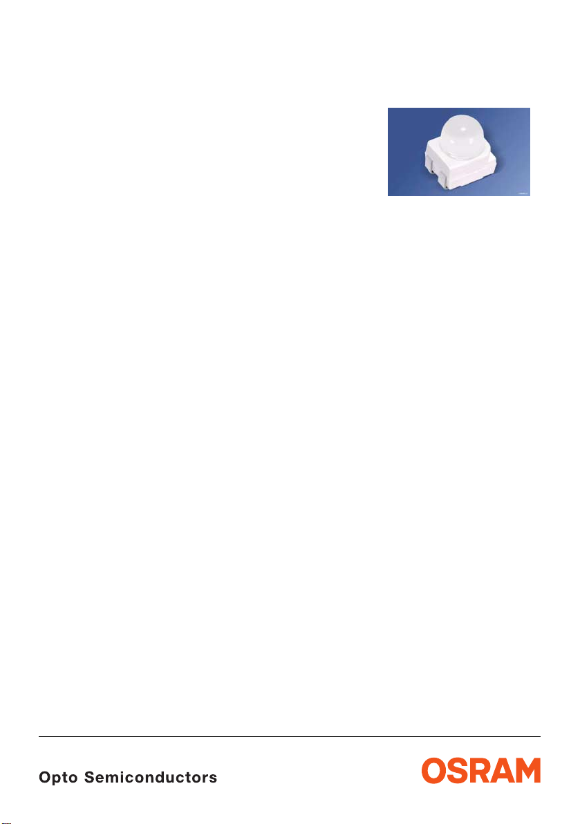
Power TOPLED
with Lens
Enhanced Thin Film LED
Lead (Pb) Free Product - RoHS Compliant
LS E63F, LA E63F, LY E63F
Vorläufige Daten / Preliminary Data
Vorläufige Daten für OS-PCN-2005-026-A für LA E63F /
Preliminary Data for OS-PCN-2005-026-A for LA E63F
Besondere Merkmale
• Gehäusetyp: weißes P-LCC-4 Gehäuse,
farbloser klarer Verguss
• Besonderheit des Bauteils: fokussierte
Abstrahlung in SMT-Technologie; hohe Helligkeit
in Achsrichtung
• Wellenlänge: 633 nm (super-red),
617 nm (amber), 590 nm (gelb)
• Abstrahlwinkel: 30°
• Technologie: InGaAlP
• optischer Wirkungsgrad: 40 lm/W (super-red),
72 lm/W (amber), 46 lm/W (gelb)
• Gruppierungsparameter: Lichtfluss,
Durchflussspannung, Wellenlänge
• Verarbeitungsmethode: für alle
SMT-Bestücktechniken geeignet
• Lötmethode: IR Reflow Löten und
Wellenlöten (TTW)
• Vorbehandlung: nach JEDEC Level 2
• Gurtung: 12 mm Gurt mit 2000/Rolle, ø330 mm
• ESD-Festigkeit: ESD-sicher bis 2 kV nach
JESD22-A114-B
Anwendungen
• Ampelanwendung
• Hinterleuchtung (LCD, Schalter, Tasten, Displays,
Werbebeleuchtung)
• Innen- und Außenbeleuchtung im Auto-
mobilbereich (z.B. Instrume ntenbeleuchtung und
Bremslichter)
• Ersatz von Kleinst-Glühlampen
• Markierungsbeleuchtung (z.B. Stufen,
Fluchtwege, u.ä.)
• Signal- und Symbolleuchten
Features
• package: white P-LCC-4 package, colorless clear
resin
• feature of the device: focussed radiation in SMT
technology; high brightness in beam direction
• wavelength: 633 nm (super-red),
617 nm (amber), 590 nm (yellow)
• viewing angle: 30°
• technology: InGaAlP
• optical efficiency: 40 lm/W (super-red),
72 lm/W (amber), 46 lm/W (yellow)
• grouping parameter: partial flux, forward voltage,
wavelength
• assembly methods: suitable for all
SMT assembly methods
• soldering methods: IR reflow soldering and TTW
soldering
• preconditioning: acc. to JEDEC Level 2
• taping: 12 mm tape with 2000/reel, ø330 mm
• ESD-withstand voltage: up to 2 kV acc. to
JESD22-A114-B
Applications
• traffic lights
• backlighting (LCD, switch es, keys, displays,
illuminated advertising)
• interior and exterior automotive ligh ting
(e.g. dashboard backlighting and brake lights)
• substitution of micro incandescent lamps
• marker lights (e.g. steps, exit ways, etc.)
• signal and symbol luminaire
2007-07-03 1
LS E63F, LA E63F, LY E63F
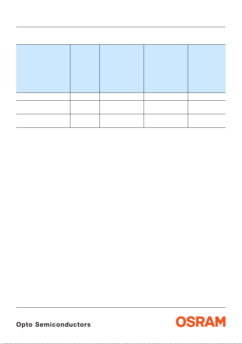
Bestellinformation Ordering Information
2) Seite 16
Typ
Type
Emissionsfarbe
Color of
Emission
Partieller
Lichtfluss
Partial Flux
I
= 50 mA
F
E
(lux)
V
1) Seite 16
1) page 16
Lichtstrom
Luminous
Flux
I
= 50 mA
F
Φ
V
2) page 16
(mlm)
LS E63F-DBFA-1-1 super-red 5600 …14000 3750 (typ.) Q65110A4105
LA E63F-EAFA-24-1
LA E63F-EBGA-24-1
LY E63F-DBEB-35-1
LY E63F-EAFA-46-1
Anm.: Die oben genannten Typbezeichnungen umfassen die bestellbaren Se lektionen . Diese besteh en aus wenigen
Helligkeitsgruppen (siehe Seite 5 für nähere Informationen). Es wird nur eine einzige Helligkeitsgruppe pro
Gurt geliefert. Z.B.: LA E63F-EAFA-24-1 bedeutet, dass auf dem Gurt nur eine der Helligkeitsgruppen EA, EB
oder FA enthalten ist.
Um die Liefersicherheit zu gewährleisten, können einzelne Helligkeitsgruppen nicht bestellt werden.
Gleiches gilt für die Farben, bei denen Wellenlängengruppen gemessen und gruppiert werden. Pro Gurt wird
nur eine Wellenlängengruppe geliefert. Z.B.: LA
Wellenlängengruppen -2, -3, oder -4 enthalten ist (siehe Seite 5 für nähere Information). Z.B.:
LS E63F-DAEA-1-1 bedeutet, dass das Bauteil innerhalb der auf Seite 4 spezi fizierte n Grenzen g eliefert wird.
Um die Liefersicherheit zu gewährleisten, können einzelne Wellenlängengruppen nicht bestellt werden.
Gleiches gilt für die LEDs, bei denen die Durchlassspannungsgruppen gemessen und gruppiert werden. Pro
Gurt wird nur eine Durchlassspannungsgruppe geliefert. Z.B.: LA
Durchlassspannung gruppiert wird. Auf einem Gurt ist nur eine der Durchlasspannungsgruppen -3B, -4A, -4B
oder -5A enthalten (siehe
Um die Liefersicherheit zu gewährleisten, können einzelne Durchlassspannungsgruppen nicht direkt bestellt
werden.
Note: The above Type Numbers represent the order groups which include only a few brightness groups (see page 5
for explanation). Only one group will be shipped on each reel (there will be no mixing of two groups on each
reel). E.g. LA
In order to ensure availability, single brightness groups will not be orderable.
In a similar manner for colors where wavelength groups are measured and binned, single wavelength groups
will be shipped on any one reel. E.g. LA
be shippable (see
the specified limits as stated on page 4.
In order to ensure availability, single wavelength groups will not be orderable.
In a similar manner for LED, where forward voltage groups are measured and binned, single forward voltage
groups will be shipped on any one reel. E.g. LA
-4A, 4B or -5A will be shippable.
In order to ensure availability, single forward voltage groups will not be orderab le (see page 5 for explanation) .
E63F-EAFA-24-1 means that only one group EA, EB or FA will be shippable for any one reel.
amber 7100 …14000
9000 …22400
yellow 5600 …11200
7100 …14000
4200 (typ.)
6000 (typ.)
3350 (typ.)
4200 (typ.)
E63F-EAFA-24-1 bedeutet, dass auf dem Gurt nur eine der
E63F-EAFA-24-1 bedeutet, dass nach
Seite 5 für nähere Information).
page 5 for explanation). E.g. LS E63F-DAEA-1-1 means that the device will b e shiped within
E63F-EAFA-24-1 means that only 1 wavelength group -2 , -3, or -4 will
E63F-EAFA-24-1 means that only 1 forward voltage group -3B,
Bestellnummer
Ordering Code
Q65110A1845
Q65110A4103
Q65110A4108
Q65110A4107
2007-07-03 2
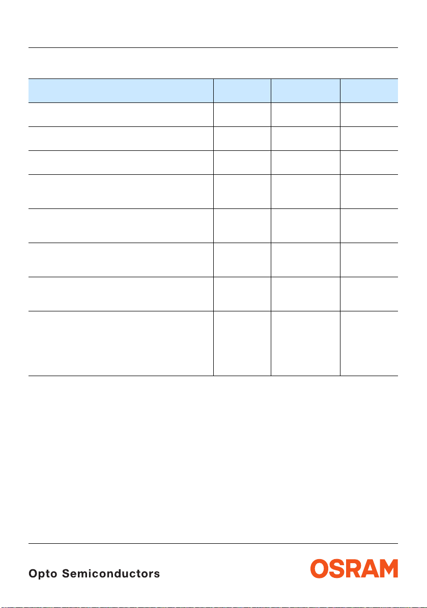
Grenzwerte Maximum Ratings
Bezeichnung
Parameter
Betriebstemperatur
Operating temperature range
Lagertemperatur
Storage temperature range
Sperrschichttemperatur
Junction temperature
Durchlassstrom
Forward current
(TA=25°C)
Stoßstrom
Surge current
t ≤ 10 μs, D = 0.1, T
Sperrspannung
Reverse voltage
A
3) Seite 16
3) page 16
=25°C
(TA=25°C)
Leistungsaufnahme
Power consumption
(TA=25°C)
Wärmewiderstand
Thermal resistance
Sperrschicht/Umgebung
Junction/ambient
4) page 16
4) Seite 16
Sperrschicht/Lötpad
Junction/soldering point
LS E63F, LA E63F, LY E63F
Symbol
Symbol
T
op
T
stg
T
j
I
F
I
FM
V
R
P
tot
R
R
th JA
th JS
Wert
Value
Einheit
Unit
– 40 … + 100 °C
– 40 … + 100 °C
+ 125 °C
70 mA
100 mA
12 V
190 mW
300
130
K/W
K/W
2007-07-03 3
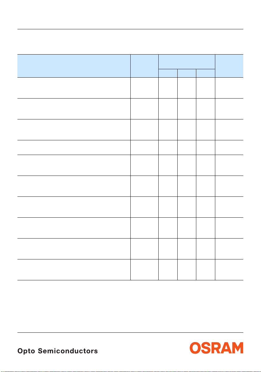
Kennwerte
Characteristics
(TA = 25 °C)
Bezeichnung
Parameter
Wellenlänge des emittierten Lichtes (typ.)
Wavelength at peak emission
I
= 50 mA
F
Dominantwellenlänge
Dominant wavelength
I
= 50 mA
F
Spektrale Bandbreite bei 50 % I
Spectral bandwidth at 50 % I
I
= 50 mA
F
5) Seite 16
5) page 16
rel max
rel max
(typ.)
Abstrahlwinkel bei 50 % EV (Vollwinkel) (typ.)
Viewing angle at 50 % E
Durchlassspannung
Forward voltage
I
= 50 mA (max.)
F
6) Seite 16
6) page 16
V
(min.)
(typ.)
Sperrstrom (typ.)
Reverse current (max.)
V
= 12 V
R
Temperaturkoeffizient von λ
Temperature coefficient of λ
I
= 50 mA; –10°C ≤ T ≤ 100°C
F
Temperaturkoeffizient von λ
Temperature coefficient of λ
I
= 50 mA; –10°C ≤ T ≤ 100°C
F
Temperaturkoeffizient von V
Temperature coefficient of V
I
= 50 mA; –10°C ≤ T ≤ 100°C
F
peak
peak
dom
dom
F
F
(typ.)
(typ.)
(typ.)
Optischer Wirkungsgrad (typ.)
Optical efficiency
I
= 50 mA
F
* Einzelgruppen siehe Seite 5
Individual groups on page 5
LS E63F, LA E63F, LY E63F
Symbol
Symbol
LS LA LY
λ
peak
λ
dom
645 624 597 nm
633
± 6
Δλ 16 18 18 nm
2ϕ 30 30 30 Grad
V
V
V
I
I
TC
TC
TC
η
F
F
F
R
R
λpeak
λdom
V
opt
1.90*
2.15
2.50
0.2 100.2 100.2
0.15 0.14 0.12 nm/K
0.05 0.08 0.10 nm/K
-2.5 -2.5 -2.5 mV/K
40 72 46 lm/W
Werte
Values
617*
–5/+7
1.90*
2.15
2.50
590*
–7/+5
2.05*
2.15
2.65
10
Einheit
Unit
nm
deg.
V
V
V
μA
μA
2007-07-03 4
LS E63F, LA E63F, LY E63F
5) Seite 16
Wellenlängengruppen (Dominantwellenlänge)
Wavelength Groups (Dominant Wavelength)
Gruppe
Group
min. max. min. max.
amber yellow Einheit
2 612 616 nm
3 616 620 583 586 nm
4 620 624 586 589 nm
5 589 592 nm
6 592 595 nm
6) Seite 16
Durchlassspannungsgruppen
Forward Voltage Groups
Gruppe
Group
min. max. min. max. min. max.
6) page 16
super-red amber yellow Einheit
3A 1.90 2.05 1.90 2.05
3B 2.05 2.20 2.05 2.20 2.05 2.20 V
4A 2.20 2.35 2.20 2.35 2.20 2.35 V
4B 2.35 2.50 2.35 2.50 2.35 2.50 V
5A 2.50 2.65 V
Helligkeits-Gruppierungsschema Brightness Groups
Helligkeitsgruppe
Brightness Group
Partieller Lichtfluss
Partial Flux
1) Seite 16
EV [lux]
DA
DB
EA
EB
FA
FB
GA
Anm.: Die Standardlieferform von Serientypen beinhaltet eine Familiengruppe. Diese besteht aus 3 bzw. 4 Helligkeitsgruppen.
Einzelne Helligkeitsgruppen sind nicht bestellbar.
Note: The standard shipping format for serial types includes a family group of 3 or 4 individual brightness groups.
Individual brightness groups cannot be ordered.
4500 … 5600
5600 … 7100
7100 … 9000
9000 … 11200
11200 … 14000
14000 … 18000
18000 … 22400
5) page 16
1) Seite 16
Lichtstärke
Luminous Intensity
IV (mcd)
4200 (typ.)
5300 (typ.)
6700 (typ.)
8500 (typ.)
10600 (typ.)
13400 (typ.)
16900 (typ.)
2) Seite 16
2) page 16
Lichtstrom
Luminous Flux
Φ
(mlm)
V
2100 (typ.)
2700 (typ.)
3400 (typ.)
4200 (typ.)
5300 (typ.)
6700 (typ.)
8500 (typ.)
Unit
Unit
2) Seite 16
2) page 16
Gruppenbezeichnung auf Etikett
Group Name on Label
Beispiel: EB-3-4A / Example: EB-3-4A
Helligkeitsgruppe
Brightness Group
Wellenlänge
Wavelength
Durchlassspannung
Forward Voltage
EB 3 4A
Anm.: In einer Verpackungseinheit / Gurt ist immer nur eine Gruppe für jede Selektion enthalten.
Note: No packing unit / tape ever contains more than one group for each sele ction.
2007-07-03 5
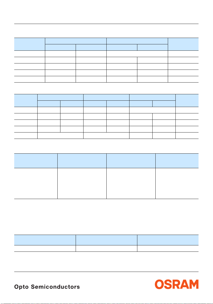
Prinzipieller Messaufbau für Partial Flux Messung Schematic test method for partial flux measurement
Referenzebene des Detektors (ø14 mm)
Reference layer of detector (ø14 mm)
LS E63F, LA E63F, LY E63F
= 40˚θ
d
OHAY0907
2007-07-03 6
LS E63F, LA E63F, LY E63F
2) Seite 16
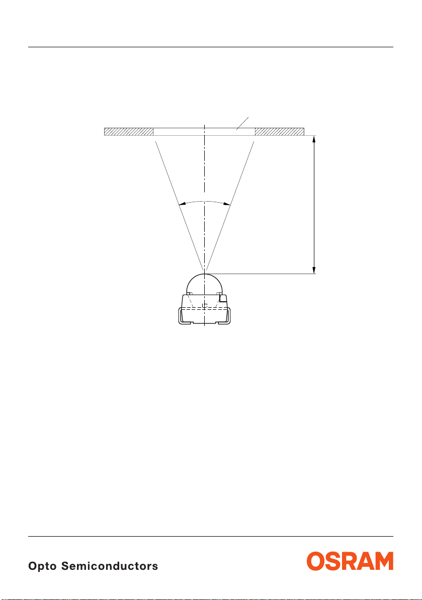
Relative spektrale Emission
Relative Spectral Emission
V(λ) = spektrale Augenempfindlichkeit / Standard eye response curve
I
= f (λ); TA = 25 °C; IF = 50 mA
rel
100
%
E
rel
80
2) page 16
V
λ
OHL22732
60
40
20
0
400
Abstrahlcharakteristik
Radiation Characteristic
I
= f (ϕ); TA = 25 °C
rel
50˚
60˚
70˚
80˚
yellow
amber
super-red
450 500 550 600 650 700nm
2) Seite 16
2) page 16
0˚10˚20˚40˚ 30˚
ϕ
1.0
0.8
0.6
0.4
0.2
λ
OHL00021
90˚
100˚
1.0 0.8 0.6 0.4
2007-07-03 7
0 20˚ 40˚ 60˚ 80˚ 100˚ 120˚
0

LS E63F, LA E63F, LY E63F
Seite 15
Durchlassstrom2)
Forward Current
I
= f (VF); TA = 25 °C
F
2
10
mA
I
F
1
10
0
10
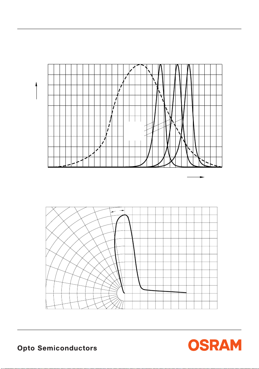
Relative Vorwärtsspannung2)
Relative Forward Voltage
ΔVF = VF - V
(25 °C)
F
2) page 15
yellow
amber
super red
2) page 15
= f (Tj); IF = 50 mA
0.25
V
V
Δ
F
0.15
OHL02710
V
2.31.5 1.7 1.9 2.1 2.5
V
F
Seite 15
OHL02667
2) 7)
Relative Lichtstärke
Seite 15
Relative Luminous Intensity
E
V/EV(50 mA)
E
= f (IF); TA = 25 °C
1
10
E
V
V (50 mA)
0
10
5
-1
10
5
-2
10
0
10 10
5
Relative Lichtstärke2)
Relative Luminous Intensity
E
V/EV(25 °C)
= f (Tj); IF = 50 mA
2.5
E
V
E
(25 ˚C)
V
2.0
Seite 15
yellow
2) 7) page 15
12
2) page 15
OHL22669
mA
I
F
OHL22711
10
0.1
0.05
0
-0.05
-0.1
-0.15
-0.2
-40
-20 0 20 40
2007-07-03 8
˚C60 100-60
T
j
1.5
1.0
0.5
0
super red
amber
-40
-60
-20 0 20 40 60
˚C
100
T
j
LS E63F, LA E63F, LY E63F
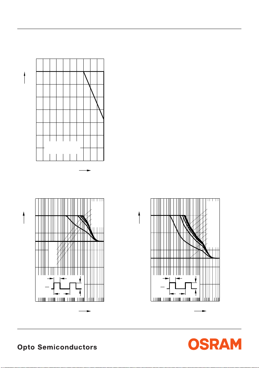
Maximal zulässiger Durchlassstrom
Max. Permissible Forward Current
I
= f (T)
F
80
mA
I
F
70
OHL01413
60
T
ATS
50
40
30
20
Τ
temp. ambient
A
10
Τ
temp. solder point
S
0
0
20 40 60 80 ˚C 100
T
Zulässige Impulsbelastbarkeit IF = f (tp)
Permissible Pulse Handling Capability
Duty cycle D = parameter, TA = 25 °C
OHL02046
=
D
0.005
0.01
0.02
0.05
I
0.12
F
0.10
A
0.08
D
0.06
0.04
0.1
0.2
0.5
=
1
Zulässige Impulsbelastbarkeit IF = f (tp)
Permissible Pulse Handling Capability
Duty cycle D = parameter, TA = 85 °C
OHL02045
=
D
0.005
0.01
0.02
0.05
0.1
0.2
0.5
1
I
0.12
F
0.10
0.08
A
0.06
0.04
t
P
0.02
2007-07-03 9
t
P
D
=
T
0
-5 1
-4
-3 -2
10
10 10
10
I
F
T
-1 0
1010
10 10s
t
p
2
t
P
0.02
t
P
D
=
T
T
0
-5 1
-4
-3 -2
10
10 10
10
I
F
-1 0
1010
10 10s
t
p
2

Maßzeichnung
8) Seite 16
Package Outlines
8) page 16
LS E63F, LA E63F, LY E63F
0.8 (0.031)
0.6 (0.024)
3.4 (0.134)
3.0 (0.118)
3.0 (0.118)
2.6 (0.102)
2.3 (0.091)
2.1 (0.083)
AA
CA
Package marking
3.7 (0.146)
(2.4) (0.095)
2.1 (0.083)
1.7 (0.067)
4˚±1
0.1 (0.004) typ
3.3 (0.130)
1.1 (0.043)
3.8 (0.150) max.
0.18 (0.007)
0.5 (0.020)
0.13 (0.005)
0.9 (0.035)
0.7 (0.028)
0.6 (0.024)
0.4 (0.016)
Gehäusekennung: abgeschrägte Ecke
Package mark: bevelled edge
Gewicht / Approx. weight: 38 mg
Gurtung / Polarität und Lage
Method of Taping / Polarity and Orientation
8) Seite 16
8) page 16
Verpackungseinheit 2000/Rolle, ø330 mm
Packing unit 2000/reel, ø330 mm
3.65 (0.144)
1.5 (0.059)
2 (0.079)
4 (0.157)
1.5 (0.059)
2 (0.079)
1.5 (0.059)
ø2.60 (0.102)
ø2.55 (0.100)
A A
AC
GPLY6113
2.9 (0.114)
8 (0.315)
2007-07-03 10
1.75 (0.069)
5.5 (0.217)
3.45 (0.136)
12 (0.472)
0.4 (0.016)
A
5˚
ACA
OHAY0736
LS E63F, LA E63F, LY E63F
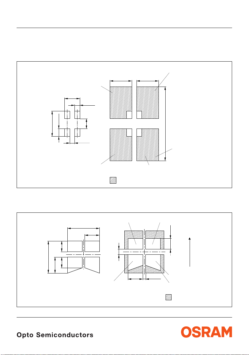
Empfohlenes Lötpaddesign verwendbar für TOPLED® und Power TOPLED
IR Reflow Löten
Recommended Solder Pad useable for TOPLED® and Power TOPLED
IR Reflow Soldering
Empfohlenes Lötpaddesign
Recommended Solder Pad
8) Seite 16
8) page 16
Padgeometrie für
verbesserte Wärmeableitung
Paddesign for
improved heat dissipation
2.3 (0.091)
0.8 (0.031)
1.1 (0.043)
3.7 (0.146)
0.7 (0.028)
Fläche darf elektrisch nicht beschaltet werden.
Do not use this area for electrical contact.
8) Seite 16
8) page 16
Anode
1.5 (0.059)
3.3 (0.130)
Lötstoplack
Solder resist
®
Fläche darf elektrisch nicht beschaltet werden.
Do not use this area for electrical contact.
3.3 (0.130)
11.1 (0.437)
Kathode/
Cathode
2
_
<
Cu Fläche / 16 mm per pad
Cu-area
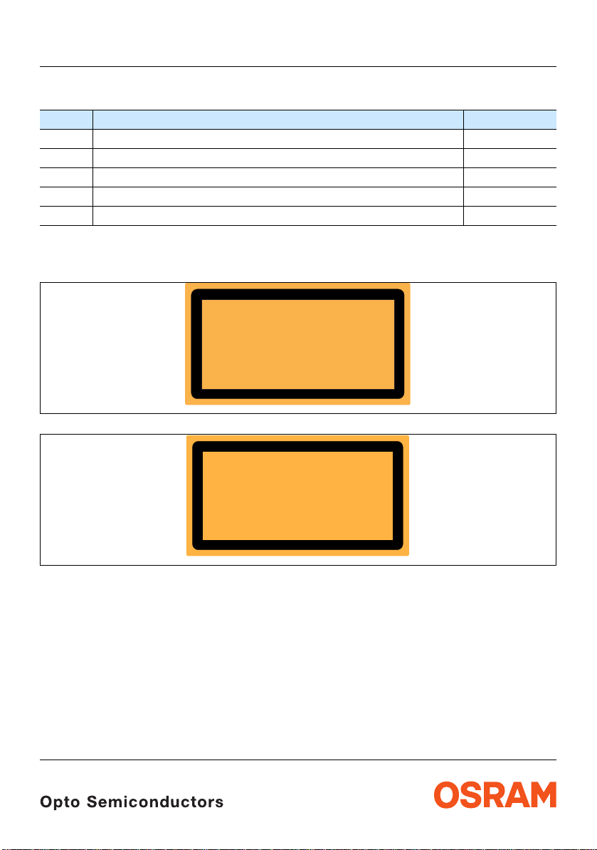
Wellenlöten (TTW)
TTW Soldering
Anode
6.1 (0.240)
2.8 (0.110)
Fläche darf elektrisch nicht beschaltet werden.
Do not use this area for electrical contact.
2 (0.079)
®
OHLPY440
2 (0.079)
6 (0.236)
2 (0.079)
3 (0.118)
Padgeometrie für
verbesserte Wärmeableitung
Paddesign for
improved heat dissipation
Fläche darf elektrisch nicht beschaltet werden.
Do not use this area for electrical contact.
1 (0.039)
2007-07-03 11
2.8 (0.110)
0.5 (0.020)
PCB-direction
Bewegungsrichtung
der Platine
Kathode/
Cathode
Cu Fläche / > 16 mm per pad
Cu-area
Lötstoplack
Solder resist
2
OHAY1583

LS E63F, LA E63F, LY E63F
Lötbedingungen Vorbehandlung nach JEDEC Level 2 Soldering Conditions Preconditioning acc. to JEDEC Level 2
IR-Reflow Lötprofil für bleifreies Löten (nach J-STD-020B) IR Reflow Soldering Profile for lead free soldering (acc. to J-STD-020B)
300
˚C
255 ˚C
250
T
200
150
100
240 ˚C
217 ˚C
min. condition for IR Reflow Soldering:
Ramp Up
3 K/s (max)
50
25 ˚C
0
0
solder point temperature ≥ 235 °C for at least 10 sec.
50 100 150 200 250 300
Maximum Solder Profile
Recommended Solder Profile
Minimum Solder Profile
120 s max
30 s max
100 s max
10 s min
Ramp Down
6 K/s (max)
Wellenlöten (TTW) (nach CECC 00802) Soldering (acc. to CECC 00802)
300
C
250
T
235 C
200
150
100
C... 260
1. Welle
1. wave
ca 200 K/s
CC... 130100
50
10 s
2 K/s
2. Welle
2. wave
5 K/s
Zwangskühlung
forced cooling
2 K/s
OHLA0687
260 ˚C
245 ˚C
235 ˚C
t
Normalkurve
standard curve
Grenzkurven
limit curves
s
+0 ˚C
-5 ˚C
±5 ˚C
+5 ˚C
-0 ˚C
OHLY0598
0
0
50 100 150 200 250
2007-07-03 12
s
t

Barcode-Produkt-Etikett (BPL) Barcode-Product-Label (BPL)
OSRAM Opto
Semiconductors
(6P) BATCH NO: Batch Number
Bar Code
Lot Number(1T) LOT NO: (9D) D/C: Date Code
Bar Code
(X) PROD NO: Product Code
Gurtverpackung Tape and Reel
D
0
P
0
P
2
LS E63F, LA E63F, LY E63F
Bin1: Bin Information Color 1
Lx xxxx
Product Name
RoHS Compliant
Product Quantity per Reel(Q)QTY:
Bar Code
Sample
W
1
±0.25
13.0
FE
A
N
W
Bin2:
Bin3:
Temp ST
ML
2
260 C RT
Additional TEXT
R077 DEMY
PACKVAR: Packing Type
X - X - X(G) GROUP:
Forward Voltage Group
Wavelength Group
Brightness Group
OHA12043
P
1
Direction of unreeling
W
2
Label
Gurtvorlauf:
Leader:
Gurtende:
Trailer:
Direction of unreeling
400 mm
400 mm
160 mm
160 mm
OHAY0324
Tape dimensions in mm (inch)
W P
+ 0.3
12
– 0.1
0
4 ± 0.1
(0.157 ± 0.004)
P
1
8 ± 0.1
(0.315 ± 0.004)
P
2
2 ± 0.05
(0.079 ± 0.002)
D
0
1.5 + 0.1
(0.059 + 0.004)
E F
1.75 ± 0.1
(0.069 ± 0.004)
5.5 ± 0.05
(0.217 ± 0.002)
Reel dimensions in mm (inch)
A W N
min
W
1
W
2 max
330 (13) 12 (0.472) 60 (2.362) 12.4 + 2 (0.488 + 0.079) 18.4 (0.724)
2007-07-03 13

LS E63F, LA E63F, LY E63F
Trockenverpackung und Materialien Dry Packing Process and Materials
Moisture-sensitive label or print
L
E
V
l
E
e
e
b
e
L
a
s
.
l
)
,
e
k
H
d
n
o
la
R
c
(
b
r
f
I
a
y
t
b
i
.
d
H
i
R
m
u
%
h
0
e
6
e
/
v
i
g
d
t
C
a
e
˚
a
r
l
k
a
c
0
e
r
S
r
f
a
3
E
N
s
R
n
p
_
<
i
V
n
%
I
i
f
O
k
0
o
O
T
s
a
o
t
T
a
I
r
9
t
I
e
.
s
S
u
s
C
d
n
)
r
r
<
p
n
o
e
N
o
U
(
e
o
T
u
t
s
o
d
r
c
H
i
d
,
E
c
o
D
t
g
n
s
i
u
o
e
S
C
r
2
n
g
H
N
j
U
a
d
i
o
c
˚
u
7
a
b
s
n
O
E
8
H
o
e
5
C
u
b
s
o
t
4
˚
C
A
R
e
s
e
4
H
I
c
a
±
s
c
U
i
0
2
d
m
e
e
y
6
M
i
o
4
T
h
r
C
t
C
b
r
˚
h
E
m
e
o
T
l
S
t
r
i
p
<
t
l
i
I
t
S
.
i
3
o
c
t
m
t
e
)
r
i
w
O
2
o
w
t
a
n
a
l
l
o
O
C
f
m
t
t
i
˚
e
r
.
M
F
a
o
l
t
s
T
t
a
l
a
o
e
c
a
h
a
r
i
P
r
h
F
l
t
o
t
d
v
t
l
o
i
u
e
n
O
n
:
a
F
o
u
f
s
d
b
l
o
4
i
e
e
w
q
e
e
r
l
a
F
,
d
l
o
m
i
5
c
c
e
l
e
i
g
a
n
l
o
v
e
r
e
v
4
s
n
r
5
e
i
e
i
e
b
o
d
e
2
t
l
p
h
v
6
L
,
o
e
d
:
n
e
e
t
e
w
l
e
c
,
g
u
v
w
e
e
a
L
k
e
r
r
d
a
o
e
o
s
d
l
v
a
%
a
u
e
e
b
f
L
l
t
r
m
e
b
e
0
b
n
e
a
s
d
u
e
L
r
i
r
1
e
t
e
r
m
e
e
e
i
r
o
o
l
s
p
e
t
e
u
s
f
i
>
e
o
t
r
a
o
s
f
,
M
r
s
o
s
u
s
3
e
i
a
k
i
e
t
o
,
s
.
i
3
s
M
o
h
s
n
b
k
o
i
l
d
0
H
p
a
,
n
r
g
n
M
o
l
-
i
F
g
n
a
a
r
a
R
b
i
l
D
M
n
e
o
b
f
C
i
h
b
f
r
T
i
t
i
p
%
k
i
l
(
f
r
s
.
.
a
S
i
I
t
a
0
r
a
f
s
o
p
e
w
l
h
t
v
e
1
a
b
J
k
t
s
e
Y
a
,
m
d
e
r
_
e
<
r
m
,
h
e
c
e
C
e
i
w
1
u
e
r
Y
e
t
t
t
t
d
i
S
t
d
o
E
o
f
o
a
n
e
l
u
>
y
.
1
W
f
r
n
n
D
u
H
i
A
I
q
d
1
d
e
e
4
o
u
.
r
e
E
s
o
e
8
y
i
r
q
r
t
J
2
m
b
e
i
M
6
/
i
e
o
t
s
b
d
1
t
)
r
:
m
i
C
e
e
2
r
i
a
S
t
d
s
c
P
o
r
m
i
m
i
e
I
)
e
r
i
o
o
t
u
v
l
b
n
o
g
m
e
e
i
r
H
F
a
e
o
t
n
c
l
i
o
D
e
)
2
p
n
r
t
k
F
o
.
a
o
l
)
e
o
a
a
r
3
b
F
o
d
b
e
l
1
e
f
l
f
l
F
I
m
2
e
a
i
e
a
r
.
t
l
e
v
2
4
e
s
d
e
l
v
3
n
L
g
e
e
l
a
v
a
e
L
e
r
e
B
e
v
t
u
e
L
t
r
e
a
s
u
e
L
i
t
D
r
o
s
e
u
i
t
r
M
o
s
u
i
t
M
o
s
i
M
o
M
OSRAM
Desiccant
Anm.: Feuchteempfindliche Produkte sind verpackt in einem Trockenbeutel zusammen mit einem Trockenmi tt el und
einer Feuchteindikatorkarte
Bezüglich Trockenverpackung finden Sie weitere Hinweise im In ternet und in unserem Short Form Catalog im
Kapitel “Gurtung und Verpackung” unter dem Punkt “Trockenverpackung”. Hier sind Normenbezüge, unter
anderem ein Auszug der JEDEC-Norm, enthalten.
Note: Moisture-senisitve product is packed in a dry bag containing desiccant and a humidity card.
Regarding dry pack you will find further information in the internet and in the Short Form Catalog in chapter
“Tape and Reel” under the topic “Dry Pack”. Here you will also find the normative references like JEDEC.
Kartonverpackung und Materialien Transportation Packing and Materials
Barcode label
Do not eat.
Avoid metal contact.
Discard if circles overrun.
bag opening.
Please check the HIC immidiately after
check dot
WET
Comparator
bake units
15%
examine units, if necessary
If wet,
bake units
10%
examine units, if necessary
If wet,
change desiccant
5%
parts still adequately dry.
If wet,
MIL-I-8835
Humidity Indicator
Humidity indicator
Barcode label
OSRAM
OHA00539
S
N
E
s
R
V
n
%
I
i
O
0
T
a
T
I
t
9
IO
S
C
n
d
<
e
N
o
U
T
t
d
c
E
c
D
g
n
e
S
g
n
N
j
U
a
i
a
b
s
O
E
b
C
u
s
˚
C
A
R
s
e
I
U
is
c
0
e
y
M
o
T
h
4
r
C
b
r
E
o
T
S
l
p
t
<
l
I
S
.
i
c
t
)
t
O
w
a
n
a
C
O
f
t
˚
e
M
l
T
t
s
a
a
a
h
P
h
l
t
v
t
i
e
n
O
:
u
s
f
b
o
i
w
q
e
a
,
l
o
m
c
e
l
i
g
n
e
r
e
v
4
n
e
i
b
o
d
e
2
t
h
,
o
d
:
n
e
w
c
,
g
u
w
e
r
d
a
o
o
s
l
%
a
e
b
f
m
e
0
b
n
e
d
r
r
1
e
e
m
e
e
i
r
o
l
p
t
e
f
e
>
o
a
s
f
r
s
o
s
3
e
a
i
e
o
,
s
.
3
s
h
k
b
o
i
l
d
0
H
p
a
n
,
g
r
n
l
-
i
F
a
n
g
r
R
a
a
b
l
i
D
n
e
o
b
f
C
b
h
i
f
T
i
t
i
p
%
i
k
(
l
f
r
s
.
.
S
i
I
t
a
0
a
f
-
o
p
w
l
h
v
t
e
1
b
J
t
e
,
a
m
d
_
<
r
m
,
h
e
c
e
e
C
w
i
r
e
t
t
t
t
d
i
S
t
o
d
E
f
o
a
n
e
l
u
y
.
f
r
n
n
u
D
i
A
I
q
d
1
d
e
e
o
u
.
r
e
E
o
s
e
y
i
r
r
q
t
2
J
m
b
i
M
/
i
o
e
t
s
b
d
t
)
r
m
:
i
C
e
2
r
i
a
S
t
d
s
c
P
o
r
m
i
i
I
)
r
e
o
o
u
v
l
b
o
n
g
e
e
r
H
F
a
o
e
n
c
l
i
o
D
e
)
2
p
n
t
k
F
o
.
a
o
l
)
e
o
a
a
r
3
b
F
o
d
b
e
l
1
e
f
l
f
l
F
I
m
e
2
a
i
e
r
a
.
t
l
e
v
2
4
e
s
d
e
l
v
n
3
L
g
e
e
l
a
a
v
e
L
e
r
e
B
e
v
t
u
e
L
t
r
e
a
s
u
e
L
i
t
D
r
o
s
e
u
i
t
r
M
o
s
u
i
t
M
o
s
i
M
o
M
Barcode label
s
998
r
1
o
t
Opto
c
02
u
0
d
1
AM
n
2
o
:
c
O
i
N
2
m
OSR
1
H
e
C
H
S
T
A
B
)
23G
P
1
6
:
(
O
N
T
O
L
)
T
1
(
N
D
O
R
P
)
X
(
Packing
Sealing label
2007-07-03 14
LEV
v
i
t
a
l
a
e
r
r
f
n
p
i
k
o
t
a
e
p
(
i
d
n
o
c
a
d
a
e
r
p
e
k
a
b
e
s
,
k
n
e
Y
1
Y
>
1
4
e
e
m
e
i
t
m
i
t
r
)
D
9
(
34
0
11
:
O
EL
el
e
b
a
l
, se
H
nk
ode
la
R
(
b
r c
If
a
y
t
b
i
d
i
m
u
h
e
e
g
d
C
a
e
˚
r
k
0
c
3
a
_
<
f
o
s
n
o
i
,
t
C
˚
5
±
C
˚
3
2
t
.
e
r
u
n
d
e
e
d
i
c
o
s
r
i
e
t
a
d
l
t
s
a
i
o
M
o
M
M
r
a
r
s
a
k
s
e
r
e
u
e
o
W
H
8
6
1
p
O
u
M
d
A
n
o
R
c
i
S
m
O
e
S
A
B
)
P
6
(
P
:
1
n
i
2
B
in
B
6
B
7
D
T6
E
L
Y
P
LS
TO
lti
u
M
4
4
01
:
C
/
D
000
2
:
Y
T
Q
)
Q
(
245
1
0
.
)
.
H
R
%
0
6
/
.
)
r
e
o
d
o
2
c
7
e
t
e
a
m
d
e
i
t
h
m
e
r
i
t
i
t
o
m
r
i
w
o
t
l
o
l
m
i
r
F
o
a
t
l
o
c
r
i
F
o
t
l
o
F
o
l
4
l
F
5
e
a
l
v
5
e
e
l
v
6
L
e
e
l
v
e
L
e
r
e
v
u
e
L
r
e
u
e
L
t
r
s
e
u
i
t
r
s
u
i
t
o
s
i
o
M
M
o
t
s
r
o
t
)
c
D
9
(
210021998
:
4
O
3
N
2
1
H
C
H
T
G
23
1
:
O
N
T
1
O
L
0
)
0
T
1
11
(
:
O
N
D
O
R
P
)
X
(
0
2
0
1
2
-
-
1
-
Q
T
:
S
:
p
R
3
m
n
Y
i
C
e
R
M
T
T
0
C
E
2
R
T
2
L
D
0
C
4
X
M
2
0
E
6
T
2
2
l
a
a
2
18
n
o
R
3
ti
i
:
d
R
d
7
A
A
7
V
0
-1
K
R
C
P
A
:
P
P
U
O
R
G
)
G
(
Muster
s
r
u
s
r
o
u
s
r
H
o
s
u
r
H
o
u
8
H
o
4
4
H
2
6
e
1
P
:
1
:
in
2
B
n
i
B
n
i
6
B
7
6
D
T
E
L
Y
P
S
L
O
ti T
l
u
4
4
1
0
:
C
/
D
00
2
:
Y
T
Q
)
Q
(
245
-1
Q
+
0
2
0
2
-
1
-
Q
T
S
:
p
R
3
m
Y
C
e
R
M
T
T
0
C
E
2
R
T
2
L
D
0
C
X
4
M
2
E
0
6
T
2
l
2
8
a
a
2
1
n
o
i
R
3
t
i
:
d
Q
R
d
7
A
+
A
7
V
1
0
-
K
R
C
P
A
:
P
P
U
O
R
G
)
G
(
0
Muster
Barcode label
-1
OSRAM
OHA02044
LS E63F, LA E63F, LY E63F
Revision History: 2007-07-03
Previous Version: 2007-03-01
Page Subjects (major changes since last revision) Date of change
1; 4 Dominant wavelength, typical Value for yellow 2005-11-02
2; 5
Anm.: Gemäß IEC 60825-1 (EN 60825-1) gilt:
Note: According IEC 60825-1 (EN 60825-1):
Brightness Group Correlation
NICHT DIREKT MIT OPTISCHEN
INSTRUMENTEN BETRACHTEN
2006-05-29
LED STRAHLUNG
LED KLASSE 1M
OHW12884
LED RADIATION
DO NOT VIEW DIRECTLY
WITH OPTICAL INSTRUMENTS
CLASS 1M LED PRODUCT
OHW02884
Attention please!
The information describes the type of component and shall not be considered as assured characteristics.
Terms of delivery and rights to change design reserved. Due to technical requirements components may contain
dangerous substances. For information on the types in question please contact our Sale s Organization.
If printed or downloaded, please find the latest version in the Internet.
Packing
Please use the recycling operators known to you. We can also help you – get in touch with your nearest sales office.
By agreement we will take packing material back, if it is sorted. You must bear the costs of transport. For packing
material that is returned to us unsorted or which we are not obliged t o accept, we shall have to invoice you f or any costs
incurred.
Components used in life-support devices or systems must be expressly authorized for such purpose! Critical
components
OSRAM OS.
2007-07-03 15
9) page 16
may only be used in life-support devices or systems
10) page 16
with the express written approval of
LS E63F, LA E63F, LY E63F
Fußnoten:
1)
Helligkeitswerte werden mit einer
Stromeinprägedauer von 25
11% ermittelt.
von ±
2)
Wegen der besonderen Prozessbedingungen bei der
Herstellung von LED können typische oder abgeleite te
technische Parameter nur aufgrund statistischer
Werte wiedergegeben werden. Diese stimmen nicht
notwendigerweise mit den Werten jedes einzelnen
Produktes überein, dessen Werte sich von typischen
und abgeleiteten Werten oder typischen Kennlinien
unterscheiden können.Falls erfor derlich, z.B. aufg rund
technischer Verbesserungen, werden diese typischen
Werte ohne weitere Ankündigung geändert.
3)
Die LED kann kurzzeitig in Sperrichtung betrieben
werden.
4)
R
ergibt sich bei Montage auf PC-Board FR 4
thJA
(Padgröße ≥ 16
5)
Wellenlängen werden mit einer Stromeinprägedauer
von 25 ms und einer Genauigkeit von ±1
6)
Spannungswerte werden mit einer
Stromeinprägedauer von 1
von ±0,05
7)
Im gestrichelten Bereich der Kennlinien muss mit
erhöhten Helligkeitsunterschieden zwischen
Leuchtdioden innerhalb einer Verpackungseinheit
gerechnet werden.
Dimmverhältnis im Gleichstrom-Betrieb max. 5:1
8)
Maße werden wie folgt angegeben: mm (inch)
9)
Ein kritisches Bauteil ist ein Bauteil, das in
lebenserhaltenden Apparaten oder Systemen
eingesetzt wird und dessen Defekt voraussichtlich zu
einer Fehlfunktion dieses lebenserhaltenden
Apparates oder Systems führen wird oder die
Sicherheit oder Effektivität dieses Apparates oder
Systems beeinträchtigt.
10)
Lebenserhaltende Apparate oder Systeme sind für
(a) die Implantierung in den menschlichen Körper
oder
(b) für die Lebenserhaltung bestimmt.
Falls sie versagen, kann davon ausgegangen werden,
dass die Gesundheit und das Leben des Patienten in
Gefahr ist.
mm 2 je Pad)
V ermittelt.
ms und einer Genauigkeit
nm ermittelt.
ms und einer Genauigkeit
Published by
OSRAM Opto Semiconductors GmbH
Wernerwerkstrasse 2, D-93049 Regensburg
www.osram-os.com
© All Rights Reserved.
Remarks:
1)
Brightness groups are tested at a current pulse
duration of 25
2)
Due to the special conditions of the manufacturing
processes of LED, the typical data or calculated
correlations of technical parameters can only reflect
statistical figures. These do not necessarily
correspond to the actual parameters of each single
product, which could differ from the typical data and
calculated correlations or the typical characteristic
line.If requested, e.g. because of technical
improvements, these typ. data will be changed without
any further notice.
3)
Driving the LED in reverse direction is suitable for
short term application.
4)
R
thJA
(pad size ≥ 16 mm 2 per pad)
5)
Wavelengths are tested at a current pulse duration of
25 ms and a tolerance of ±1
6)
Forward voltages are t ested at a current pulse duration
of 1
7)
In the range where the line of the graph is broken, you
must expect higher brightness differences between
single LEDs within one packing unit.
Dimming range for direct current mode max. 5:1
8)
Dimensions are specified as follows: mm (inch)
9)
A critical component is a component used in a
life-support device or system whose failure can
reasonably be expected to cause the failure of that
life-support device or system, or to affect its safety or
the effectiveness of that device or system.
ms and a tolerance of ± 11%.
results from mounting on PC board FR 4
nm.
ms and a tolerance of ±0.05 V.
10)
Life support devices or systems are intended
(a) to be implanted in the human body,
or
(b) to support and/or maintain and sustain human life.
If they fail, it is reasonable to assume that the health
and the life of the user may be endangered.
2007-07-03 16
 Loading...