

Page 1
HALOTRONIC
®
Electronic transformers for 12 V
halogen lamps
• Optimum lamp life
• Compact for small spaces
• Reversible switch off in case of shortcircuits, overload and overtemperature
• Dimming on the primary side is
possible. A corresponding dimmer
has to be used (suitable dimmers see
table)
Connecting the transformers to the
lamps
• Ensure that the lamp load is within the
output range of the transformers (see
table)
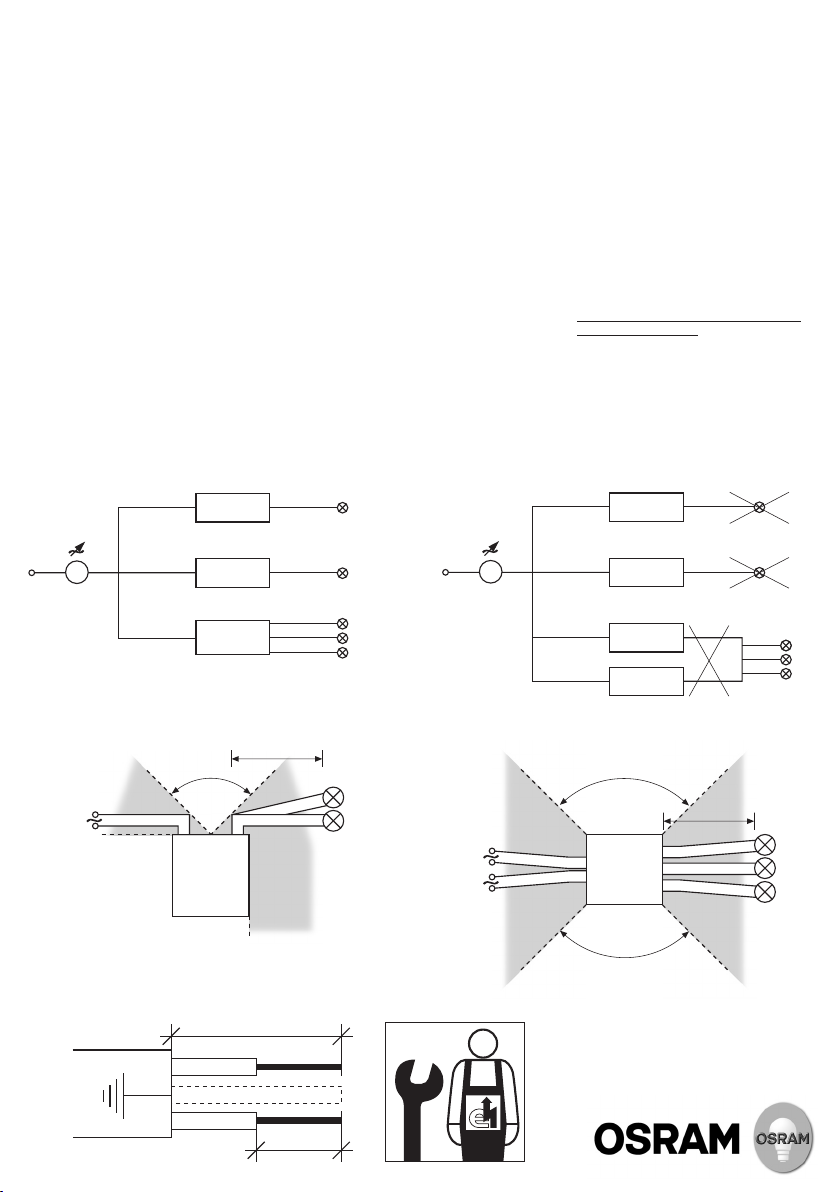
• Transformers can be connected in
parallel on the primary side (fig. 1a)
• Do not connect the transformers in
parallel or series on the secondary
side (fig. 1b)
• The maximum load of the transformer
can be connected to any of the lampside terminal pairs (except HTL 225)
Wiring
• In accordance with the EN 60598
standard, the recommended
connecting cables (see table) must be
held firmly by the cable clamp to
prevent it from being pushed or pulled
• Secondary side: cable length maximum
2 m, minimum 0.3 m (fig. 2 and 3)
• To prevent radio interference keep lamp
cables as short as possible, keep them
away from metal surfaces and keep
them separated as far as possible from
mains cables (fig. 2 and 3: angles ≥ 90°).
Do not route cables along the
transformers
• When using single leads of a cable,
secondary wires have to be twisted
in pairs
correct incorrect
1. a
HALOTRONIC
105 W
HALOTRONIC
105 W
HALOTRONIC
105 W
100 W
35 W
35 W
35 W
35 W
1. b
• For units installed in fixtures the
luminaire manufacturer is responsible
for RFI-compliance
Temperatures
• Avoid high temperatures. Do not place
the transformers close to the lamp
(minimum distance 0.3 m). Maximum
permissible ambient temperature must
not be exceeded (see table). Make sure
there is adequate space to avoid a
build-up of heat. In critical installations
the temperature at tc has to be
controlled
Caution
•
Transformers must be installed by a
qualified electrician
• Electronic transformers are not suitable
for any other load than low voltage
halogen lamps
• No switching or dimming on secondary
side
HALOTRONIC
105 W
HALOTRONIC
105 W
HALOTRONIC
105 W
HALOTRONIC
105 W
120 W
10 W
2.
max. 2 m
min. 0.3 m
90° 90°
Prim. Sec.
HTM 105
HTN 75
HTM 70
Optimum
area for
secondary
cables
230 – 240 V
50 – 60 Hz
Optimum
area for
primary cable
4. Wire stripping (see table)
A
not used
B
3.
mains
next
unit
Optimum
area for
primary cables
HTL 105
HTL 225
HTM 150
Prim. Sec.
90°
max. 2 m
min. 0.3 m
Optimum
area for
secondary
cables
Page 2

HALOTRONIC
®
HTM 70/230-240 HTM 105/230-240 HTM 150/230-240
Nominal line voltage: 230 V – 240 V
Operating voltage: 207 V – 254 V
Safe operation: 207 V – 264 V
Nominal line current: 0.27 A
0.41 A
eff
0.57 A
eff
eff
Line frequency: 50 – 60 Hz
Output voltage (230 V): 11.2 V (70 W); 11.2 V (20 W) 11.3 V (105 W); 11.4 V (35 W) 11.4 V (150 W); 11.5 V (50 W)
Losses: max. 4 W (70 W) max. 6 W (105 W) max. 7 W (150 W)
Load range: 20 W – 70 W 35 W – 105 W 50 W – 150 W
Standards: EN 55015; EN 61000-3-2; EN 61547; EN 61047; IEC 61347
Approvals:
Temperature range: 0 °C to +50 °C 0 °C to +45 °C
Max. inrush current for cold lamps: 0.3 A
Dimming: trailing
(70 W) 1.0 A
eff
or leading edge phase control for inductive load dimmers
(105 W) 1.1 A
eff
eff
(150 W)
Short circuit protection: automat. switch off, reversible
Overload protection: automat. switch off, reversible
Overheating protection: automat. switch off, reversible
Suitable cable types for primary side:
Suitable cable types for secondary side:
Stripping lengths (fig. 4):
A 12 mm 12 mm
B 7 mm 8 mm
NYM(3 x1.5) mm2; H05VV-F(3x 0.75 – 3x 1.5) mm
H05VV-F(2x 0.75 – 2x 1.5) mm2; H05VV-H2F(2x 0.75 – 2x 1.5) mm
NYM(3 x1.5) mm
H05VV-F(3x 0.75 – 3x 1.5) mm
H05VV-F(2x 0.75 – 2x 1.5) mm
H05VVH2-F(2 x0.75 – 2x 1.5) mm
cable sheath cross section (6x 3.5) mm2 to (8x 5) mm
same cable type recommended as used at primary side
the sheath cross section must be equal to that of primary side
2
2
2
2
2
2
2
connection of 2 lines of the types
NYM 3x 1.5; H05VV-F(3 x1.5 – 3x 1.0)
connection of 3 lines of the types NYM 3x 1.5;
H05VV-F(2x 1.5 – 2x 0.75); H03VV-F(2x1.5 – 2x 0.75)
Halogen low voltage line 2x 1.5; 2 x2.5:
cable sheath cross section (6x 3.5) mm
connection of 6 lines of the types H05VV-F2x 0.75;
H03VV-F2x 0.75 Halogen low voltage line 2x1.5:
cable sheath cross section (6x 3.5) mm
G10252879C10238698
2
to (9x 6) mm
2
to (7x 5) mm
2
2
Nominal line voltage:
Operating voltage:
Safe operation:
Range of battery voltage for
emergency installation:
Nominal line current:
Line frequency:
Output voltage (230 V):
Losses:
Load range:
Standards:
Approvals:
Temperature range:
Max. inrush current for cold lamps:
Dimming:
Short circuit protection:
Overload protection:
Overheating protection:
Suitable cable types for primary side:
Suitable cable types for secondary side:
Stripping lengths (fig. 4):
HTN 75/230-240 I
HT 120/230-240/12 LF HTL 105/230-240 HTL 225/230-240
230 V – 240 V
207 V – 254 V
207 V – 264 V 207 V – 264 VAC, 176 V – 275 VDC
0.32 A
eff
–
0.48 A
0.44 A
eff
0.90 A
eff
176 V – 275 V
50 – 60 Hz 50 Hz 0; 50 – 60 Hz
11.5 V (75 W), 11.5 V (120 W), 11.6 V (105 W), 11.6 V (225 W),
11.7 V (20 W) 11.5 V (35 W) 11.3V (35 W) 11.7 V (50 W)
max. 4 W (75 W) max. 6 W (120 W) max. 6 W (105 W) max. 9 W (225 W)
20 W – 75 W 35 W – 120 W 35 W – 105 W 50 W – 225 W
EN 55015; EN 61000-3-2; EN 61547; EN 61047; IEC 61347
0 °C to +50 °C -20 °C to +45 °C -20 °C to +50 °C
0.37 A
(75 W) 2 A
eff
trailing edge phase control trailing
(120 W) 0.6 A
eff
(105 W) 1.5 A
eff
or leading edge phase control
eff
automat. switch off, reversible
automat. switch off, reversible
NYM(3x 1.5) mm
H05VV-F(2x 0.75) mm
H03VV-F(2x 0.75) mm
H03VVH2-F(2x 0.75) mm
10 mm 15 mm 14 mm
A
6 mm 7 mm 8 mm
B
OSRAM GmbH
Steinerne Furt 62
86167 Augsburg, Germany
www.osram.com
2
2
2
2
H03VV-F2x 0.50 mm
H03VVH2-F2x 0.75 mm2; NYM-O 2x 1.5 mm2; NYM-J 3x 1.5 mm2; H05VV-F2x 2.5 mm
H03VV-F2x 0.75 mm2; H05VVH2-F2x 0.75 mm2; NYM-O 2x1.5 mm2;
H05VV-F2x1.5 mm
automat. switch off, reversible
2
; H03VV-F2x 0.75 mm2; H05VVH2-F2x 0.75 mm2;
2
; H05VV-F2x 2.5 mm2; NYM-J 3x 1.5 mm2; NYM-J 3x 2.5 mm
eff
(225 W)
2
2
 Loading...