

Page 1
EASY PB Coupler
1
2
3
4
S1
S2
S3
S4
T1
GND
T2T3T4
GND
T5
T8T7T6
A
Description
C
Function and application
The EASY PB Coupler is connected to an EASY control unit
via the supplied Y-connector and thus enables the connection
of standard pushbuttons, switches, motion detectors or timer
switches with a potential-free closer contact to an EASY light
control system.
The EASY PB coupler is installed in a ush device box behind
A
the respective switch insert, pushbutton insert or distributor box.
Function
The EASY PB Coupler converts the button or switch operations to corresponding digital telegrams and transmits them
to the control units of type DALI EASY II or OT EASY 60. The
functions of the connected pushbuttons or switch contacts are
B
assigned by means of the DIP switch setting.
The EASY PB Coupler is operated with safety extra low voltage
and is directly supplied over the EASY signal line. An additional
supply is not necessary.
Pushbutton coupler
Operating instructions
D
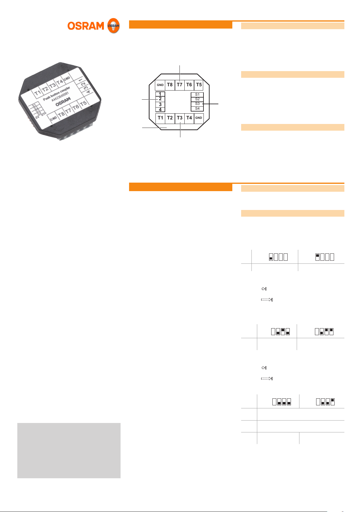
Operation
Design
The pushbutton coupler is made up of the following components:
• Connection terminals T1 to T8 for up to eight pushbuttons,
switches or potential-free contacts (A)
• DIP switches (B)
• Connection terminals for signal lines (C)
• Housing (D)
Function of the DIP switches
The functions of the connected pushbuttons or switch contacts
are assigned by the positions of the DIP switches.
Operation via pushbuttons
Note: Operation via pushbuttons is analogous to operation via a
remote control. See the separate instructions of the DALI EASY
II and OT EASY 60 control units.
Disabling of lighting scene storage
Storing of scenes can be disabled by means of DIP switch 1.
On
Scene storage is disabled Scene storage is enabled
Pure lighting scene operation
Short press:
The corresponding scene is called up.
Long press:
The current lighting situation is stored.
Continuous press:
As long as the pushbutton is pressed, consecutive scenes are
called up at intervals of 2 s.
On
IV 2009
EASY_PB_Coupler_ba0904en_we1.01.indd
OSRAM GmbH
Kunden Service Center
Customer-Service-Center (CSC)
Steinerne Furt 62
86167 Augsburg
Germany
Tel : +49 (0) 1803 677 - 200
(kostenpichtig / charges apply)
Fax.: +49 (0) 1803 677 - 202
www.osram.com
www.osram.de
40083219155974
4008321915597
On
T 1...8 Store and call up
lighting scenes 1...8
Lighting scene, channel and central unit operation
Short press:
The selected channel or the entire lighting is switched on or off.
Long press:
Brightness is changed manually. The dimming direction
changes with every long press.
On
T 1...4 Luminaire groups (channels) 1...4:change bright-
ness manually/switch on and off
T 5 All luminaires: change brightness manually/switch
on and off
T 6…8 Store and call up
lighting scenes 1...3
Page 1 of 2
On
Store and call up lighting
scenes 9...16
On
Store and call up lighting
scenes 4...6
Page 2
Operation (cont.)
Pure sequence mode operation
Short or long press: The corresponding sequence is started or
stopped.
On
T 1...4 Start sequence mode with sequence A..D
T 5 All luminaires: change brightness manually/switch
on and off
T 6 Resume paused sequence
T 7 Pause running sequence
T 8 Call up the next lighting scene
Light scenes and sequence mode operation
On
T 1...4 Store and call up lighting scenes 1...4
T 5 All luminaires: change brightness manually/switch
on and off
T 6 Start sequence mode with sequence A/resume
paused sequence
T 7 Pause running sequence
T 8 Call up the next lighting scene
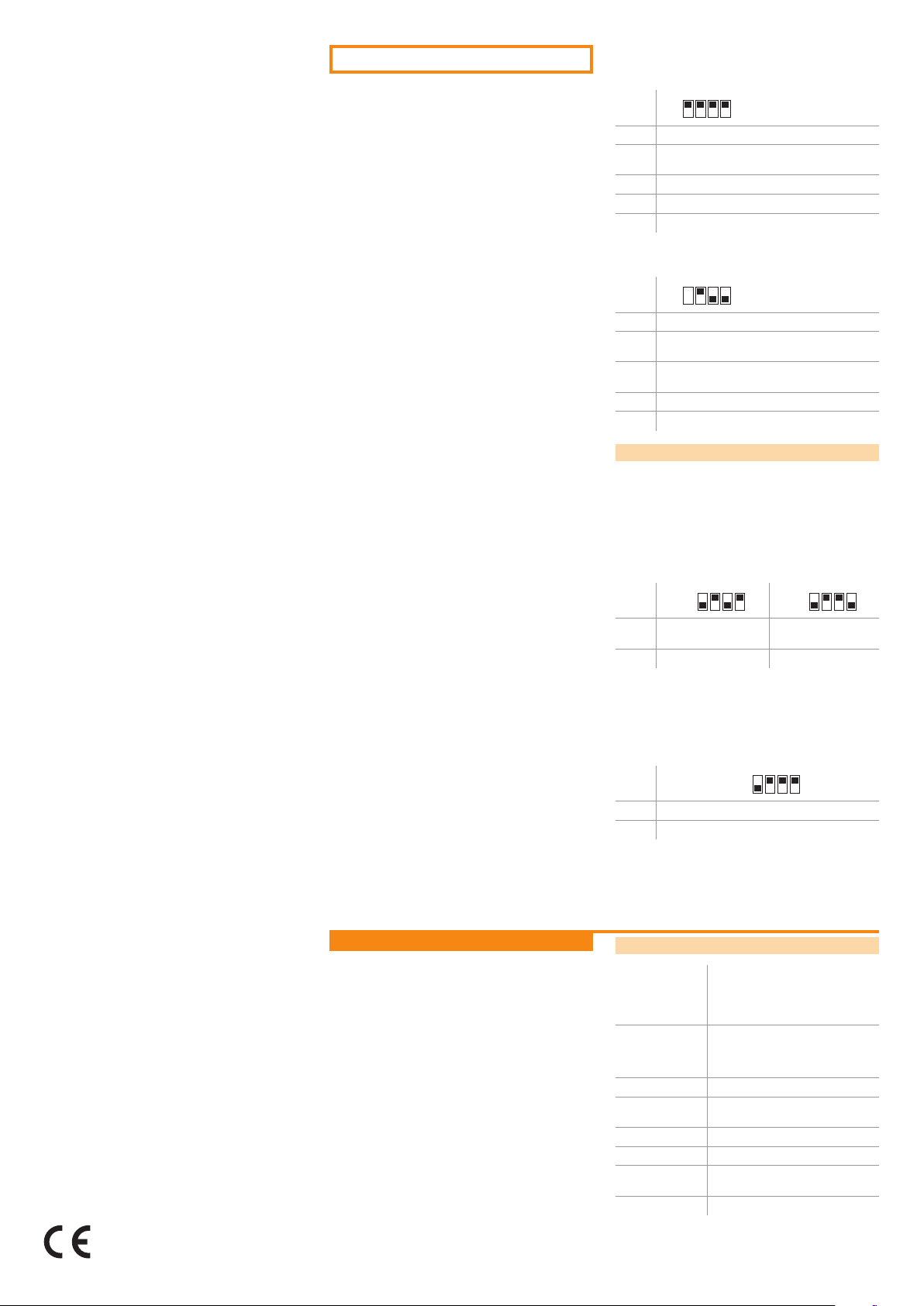
Operation via switches or motion detector
Lighting scene operation
Close switch contact:
lighting scenes 1...15 are called up (depending on the DIP
switch setting).
Open switch contact:
lighting scene 16 is called up (default setting: all luminaires off).
For the unit to function effectively, only one of the contacts on
inputs T1 to T8 may be switched at any one time.
The CE requirements are fullled: EMC requirements as per
EN 61547, low voltage as per EN 60928.
Conformity with the relevant EU directives is
conrmed by the CE symbol.
Appendix
Pushbutton
T 1...7 Store and call up ligh-
T 8 Call up lighting scene 8 –
Sequence mode operation
Close switch contact:
sequence A..D is started
Open switch contact:
lighting scene 16 is called up (default setting: all luminaires off).
Push-
button
T 1...4 Start sequence mode with sequence A..D
T 5...8 –
On
ting scenes 1...7
On
On
Store and call up ligh-
ting scenes 9...15
Technical data
Outputs EASY signal, 4-pin, SELV
Inputs 8 inputs for potential-free closer
Leads diameter 0.25 …1.5 mm²
Operating tempe-
rature
Protection type IP 20
Protection class III
Dimensions
(L x W x H)
LED message Communication: LED ashes
• Max. 50 m line length to the next
control unit
• Max. 100 m total line length
contacts,max. 25 m line length at one
input,max. 50 m total line length over
all inputs
0 °C …+ 50 °C
47 x 44 x 13 mm
Page 2 of 2
 Loading...