

Page 1
www.osram.com
Economical long-life light
sources with plug-in base
Compact uorescent lamps OSRAM DULUX®
Technical Guide
Page 2

Page 3

EDITION: 04.2011
Subject to change without notice.
Despite careful review, the possibility of mistakes can’t be excluded – no guaranty will be taken.
Page 4

Economical long-life light sources with plug-in bases
Compact Fluorescent Lamps OSRAM DULUX®
Technical Guide
1 GENERAL ...................................................................................................................................... 5
1.1 Introduction .............................................................................................................................. 5
1.2 The OSRAM DULUX® range ....................................................................................................... 6
1.2.1 Lamps with integrated starter and two-pin base for conventional operation ............... 6
1.2.2 Lamps with four-pin bases for operation with electronic control gear (ECG) ................ 9
1.2.3 High efficiency (HE) lamps for operation with electronic control gear (ECG): ............. 10
1.2.4 Lamps with four-pin bases for conventional or ECG operation .................................... 13
1.2.5 Lamps for special Applications: .................................................................................... 15
1.3 Economy and suitability ......................................................................................................... 19
1.4 Technical design and operation.............................................................................................. 20
1.4.1 Radio interference suppression .................................................................................... 22
1.5 Which accessories are needed for OSRAM DULUX® lamps? .................................................. 23
2 LAMP DATA ................................................................................................................................ 24
2.1 Geometric data ....................................................................................................................... 24
2.1.1 OSRAM DULUX® S ......................................................................................................... 24
2.1.2 OSRAM DULUX® S/E ...................................................................................................... 24
2.1.3 OSRAM DULUX® D ......................................................................................................... 25
2.1.4 OSRAM DULUX® D ES .................................................................................................... 25
2.1.5 OSRAM DULUX® D/E ..................................................................................................... 25
2.1.6 OSRAM DULUX®T PLUS ................................................................................................. 26
2.1.7 OSRAM DULUX® T CONSTANT ...................................................................................... 26
2.1.8 OSRAM DULUX® T/E PLUS ............................................................................................. 26
2.1.9 OSRAM DULUX® T/E CONSTANT ................................................................................... 27
2.1.10 OSRAM DULUX® T/E HE ................................................................................................ 27
2.1.11 OSRAM DULUX® L ......................................................................................................... 28
2.1.12 OSRAM DULUX® L HE .................................................................................................... 28
2.1.13 OSRAM DULUX® F ......................................................................................................... 29
2.1.14 OSRAM CFL SQUARE® ................................................................................................... 30
2.2 Operation modes and electrical data ..................................................................................... 31
2.2.1 Electronic operation ..................................................................................................... 31
2.2.2 Inductive operation Single-lamp circuit ........................................................................ 32
2.2.3 Inductive operation Series circuit ................................................................................. 33
2.2.4 Inductive operation Lead-lag circuit ............................................................................. 33
2.3 Photometric data .................................................................................................................... 34
2.3.1 Light colours ................................................................................................................. 34
2.3.2 Colour specifications .................................................................................................... 35
2.3.3 Chromaticity coordinates tolerance fields .................................................................... 35
2.3.4 OSRAM DULUX® light colours ....................................................................................... 36
2.3.5 Factors affecting colour consistency ............................................................................ 37
2.3.6 Spectral distribution ..................................................................................................... 38
2.3.7 Radiation components in the ultra-violet range: ......................................................... 39
2.3.8 Radiation components in the infra-red range .............................................................. 40
2.3.9 Luminous intensity distribution charts ......................................................................... 41
2.3.10 Luminance of OSRAM DULUX® lamps ........................................................................... 43
2.4 Lamp life and maintenance .................................................................................................... 44
2.4.1 Definitions .................................................................................................................... 44
2.4.2 Maintenance for OSRAM DULUX® lamps ..................................................................... 44
2.4.3 Mortality charts of OSRAM DULUX® lamps .................................................................. 44
2.4.4 Effect of switching operations on lamp life .................................................................. 44
2
Page 5

Economical long-life light sources with plug-in bases
Compact Fluorescent Lamps OSRAM DULUX®
3 CIRCUITS .................................................................................................................................... 46
Technical Guide
3.1 Operation with electronic control gear (ECG) ........................................................................ 46
3.2 Operation with conventional control gear (CCG) ................................................................... 47
3.2.1 Permissible lamp/CCG combinations and system data ................................................ 47
3.2.2 Compensation .............................................................................................................. 49
3.2.3 Operation of OSRAM DULUX® S/E, D/E und T/E PLUS with external starter and CCG .. 50
3.3 Operating on dc sources ......................................................................................................... 51
3.3.1 Compact fluorescent lamps in emergency lighting ...................................................... 52
3.4 Operation with motion detectors and light sensors .............................................................. 53
3.5 Dimensioning of automatic circuit breakers .......................................................................... 53
4 OPERATING CHARACTERISTICS ............................................................................................ 54
4.1 Start-up characteristics........................................................................................................... 54
4.1.1 Single circuit, inductive operation ................................................................................ 54
4.1.2 Series circuit, inductive operation ................................................................................ 55
4.2 Starting at low temperatures ................................................................................................. 55
4.3 Run-up behaviour ................................................................................................................... 56
4.4 Operating values of the lamps as a function of mains voltage .............................................. 59
4.5 Operating values of the lamps as a function of ambient temperature .................................. 60
4.6 Luminous flux as a function of temperature and operating position .................................... 62
4.6.1 Luminous flux/temperature graphs for OSRAM DULUX® lamps in general .................. 63
4.6.2 Luminous flux/temperature graphs for OSRAM DULUX® HE base up (horizontal) ....... 63
4.6.3 Luminous flux/temperature graphs for OSRAM DULUX® CONSTANT lamps ................ 64
4.6.4 Luminous flux/temperature graphs for OSRAM DULUX® L SP for outdoor lighting ..... 64
4.6.5 Luminous flux/temperature graphs for OSRAM DULUX® L Constant ........................... 65
4.6.6 Operation at high temperatures .................................................................................. 66
4.6.7 Operation at low temperatures.................................................................................... 66
4.7 Dimming ................................................................................................................................. 67
4.7.1 Dimming of OSRAM DULUX CONSTANT lamps ............................................................ 67
4.8 Lamp temperature, safety and limit values............................................................................ 71
4.8.1 Maximum temperatures for OSRAM DULUX® lamps .................................................... 72
4.8.2 Maximum electrical safety values for OSRAM DULUX® lamps as per IEC 61199 ......... 75
5 DATA FOR CONTROL GEAR MANUFACTURERS .................................................................. 77
5.1 Electronic operation ............................................................................................................... 77
5.1.1 Preheating (ECG operation) ......................................................................................... 77
5.1.2 Starting (ECG operation) .............................................................................................. 78
5.1.3 Operating data for undimmed lamps ........................................................................... 80
5.1.4 Dimming ....................................................................................................................... 81
5.2 Magnetic operation ................................................................................................................ 85
5.2.1 Magnetic operation 220 V/230V and 240V, 50Hz/60Hz .............................................. 85
5.3 Electrical data for the filaments ............................................................................................. 86
6 ACCESSORIES ........................................................................................................................... 87
6.1 Caps and lampholders ............................................................................................................ 87
6.2 Lamp supports ........................................................................................................................ 88
6.3 Starters ................................................................................................................................... 89
3
Page 6

Economical long-life light sources with plug-in bases
Compact Fluorescent Lamps OSRAM DULUX®
Technical Guide
7 MEASURING OSRAM DULUX® COMPACT FLUORESCENT LAMPS .................................... 90
7.1 Ageing of lamps ...................................................................................................................... 90
7.2 Operating position .................................................................................................................. 91
7.3 Constant photometric values ................................................................................................. 91
7.4 Electrical measurements ........................................................................................................ 91
7.5 Temperature measurements.................................................................................................. 92
7.5.1 Ambient temperature ................................................................................................... 92
7.5.2 Cold spot temperature for lamps without amalgam ................................................... 92
7.5.3 Measuring CONSTANT lamps ....................................................................................... 92
7.6 Reference lamps ..................................................................................................................... 93
8 OSRAM DULUX® AND THE ENVIRONMENT ........................................................................... 94
8.1 Contents ................................................................................................................................. 94
8.2 Waste disposal ........................................................................................................................ 94
8.3 ROHS Directive and conformity for compact fluorescent lamps ........................................... 95
9 EUROPEAN AND INTERNATIONAL STANDARDS .................................................................. 96
9.1 Relevant standards ................................................................................................................. 96
9.1.1 Lamps and caps ............................................................................................................ 96
9.1.2 Accessories ................................................................................................................... 96
9.1.3 Luminaires .................................................................................................................... 97
9.1.4 Miscellaneous ............................................................................................................... 98
9.1.5 Sources ......................................................................................................................... 99
9.2 Declaration of Conformity .................................................................................................... 100
9.3 CE labelling ........................................................................................................................... 104
9.4 Energy Efficiency Index ......................................................................................................... 104
4
Page 7

Economical long-life light sources with plug-in bases
Compact Fluorescent Lamps OSRAM DULUX®
1 General
1.1 Introduction
The first compact fluorescent lamps (CFLs) appeared on the European market in the early 1980s.
Ever since, they have had a significant and lasting effect on light fitting design and lighting applications. Today, CFLs are available in an extremely wide range of models.
They can be divided into two main groups:
lamps with pin bases and
lamps with screw bases
Lamps with E27 or E14 screw bases and integrated control gear (electronic or conventional) are
available in wattages from 3 to 30 W. They constitute a separate family of lamps.
Examples are the OSRAM DULUX® EL and CIRCOLUX® EL lamps. These ranges are intended as
direct replacements for ordinary incandescent light bulbs. For detailed technical information on
these lamps, please refer to the brochure titled „OSRAM DULUX® EL Electronic Energy-Saving
Lamps – Facts and Technical Data“.
Technical Guide
This present guide, however, takes a detailed look at lamps with pin bases.
OSRAM’s compact fluorescent lamps with pin bases marketed under the OSRAM DULUX® brand
name are available in wattages from 7 to 80 W with luminous flux values of 405 to 6000 lm. This
range of values covers a broad spectrum of lamps, including incandescent, fluorescent and HID
lamps, with a wide variety of applications.
Lamps with pin bases have a history of constant development, from the single-turn OSRAM
DULUX® S models to the latest OSRAM DULUX® L 80 W with CONSTANT Amalgam technology and
the DULUX
®
HE High Efficiency lamp range with up to 100lm/W efficiency. The development of
different shapes and wattages has led to various types of light fittings for both, indoor and outdoor
lighting. The list includes recessed and surface-mounted light fittings for shops and offices, floorstanding lights, indirect light fittings, workplace and desktop lighting, security lighting, pictogram
illumination, street lighting, solar light fittings and downlights.
For downlights in particular, pin-based lamps have been instrumental in determining their design, as
each successive round of development has produced increasingly shorter lamps of greater light
output.
Compact fluorescent lamps from OSRAM, which offer impressive savings thanks to a luminous
efficacy of up to 100 lm/W and a lamp life of up to 20 000 or 36 000 hours for long life range (XT) on
ECG operation, are available not only in a wide range of types but also in different light colours.
These light colours are classified in colour rendering groups 1B (Ra 80 to 89) and 1A (Ra 90 to 100).
The range also includes various models for special applications in medicine, cosmetics and technology.
The following sections present the range of pin-based lamps, their properties, the necessary accessories accompanied by notes on light fitting design, lamp applications and measurement.
5
Page 8

Economical long-life light sources with plug-in bases
5 W
257 lm
7 W
405 lm
9 W
600 lm
11 W
900 lm
Light colours
LUMILUX® 827, 830, 840, 865*
Red 60**, Green 66**, Blue 67**
* reduced luminous flux. Consult ww.osram.com
** lumen value not defined. Consult www.osram.com
With built in glow starter
Only for CCG operation
G23, 2 pin base
Average life time: 10,000 h
Compact Fluorescent Lamps OSRAM DULUX®
Technical Guide
1.2 The OSRAM DULUX
OSRAM DULUX
®
lamps are innovative light sources with the following features:
®
range
Small dimensions
Low power consumption
High luminous efficacy
Long life
Low thermal output
Different light colours
Excellent colour rendering
Wide range of types and wattages
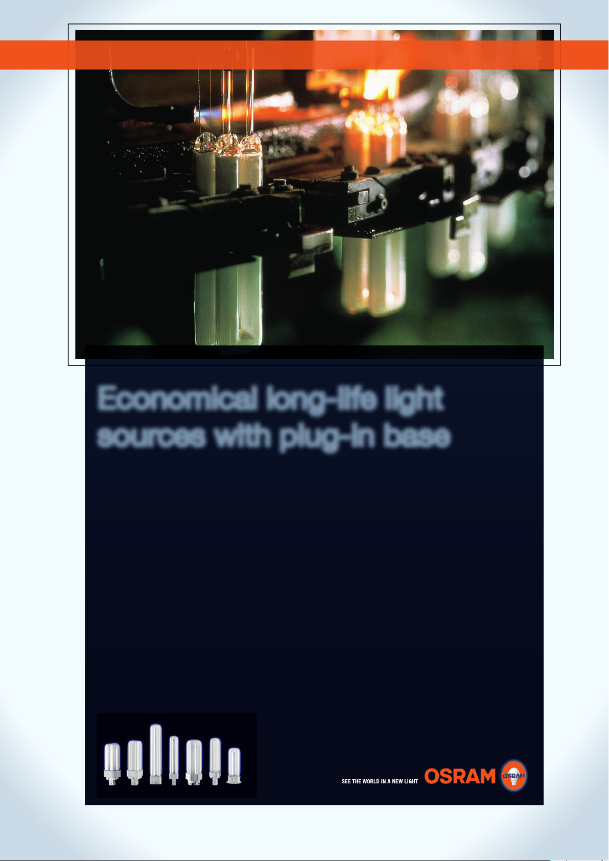
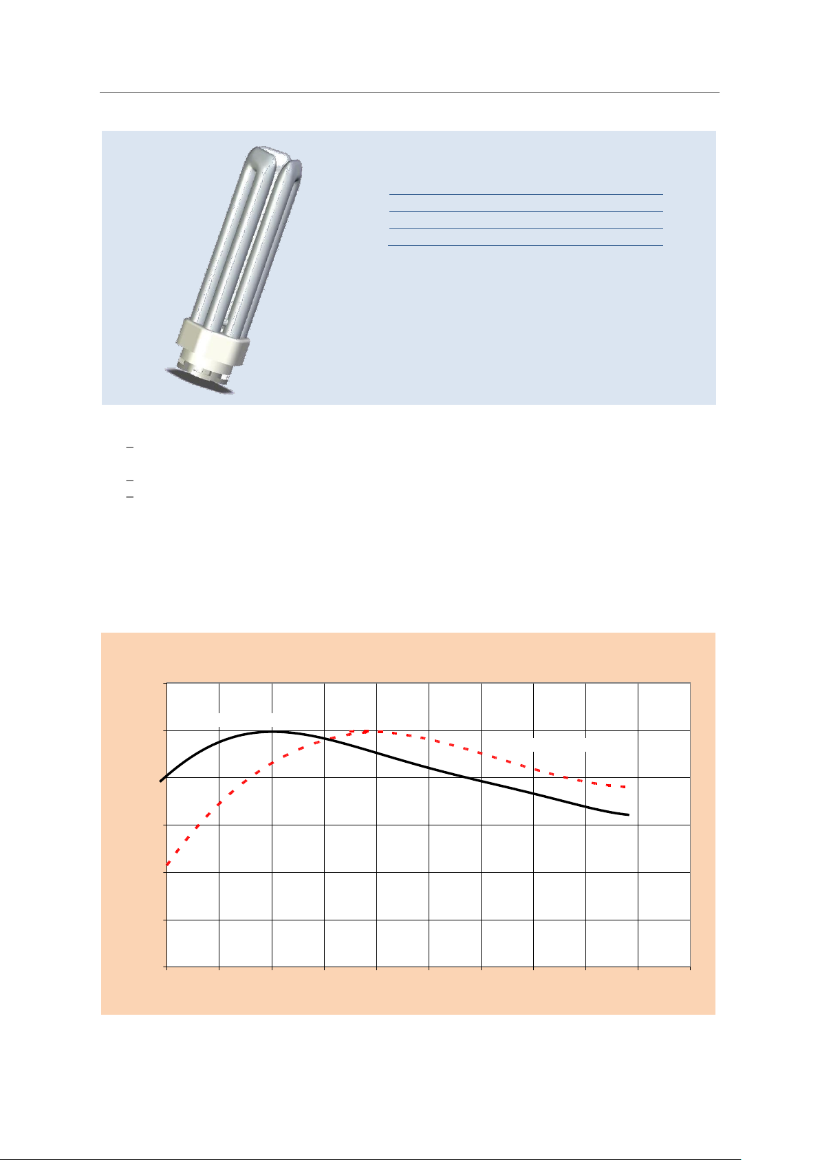
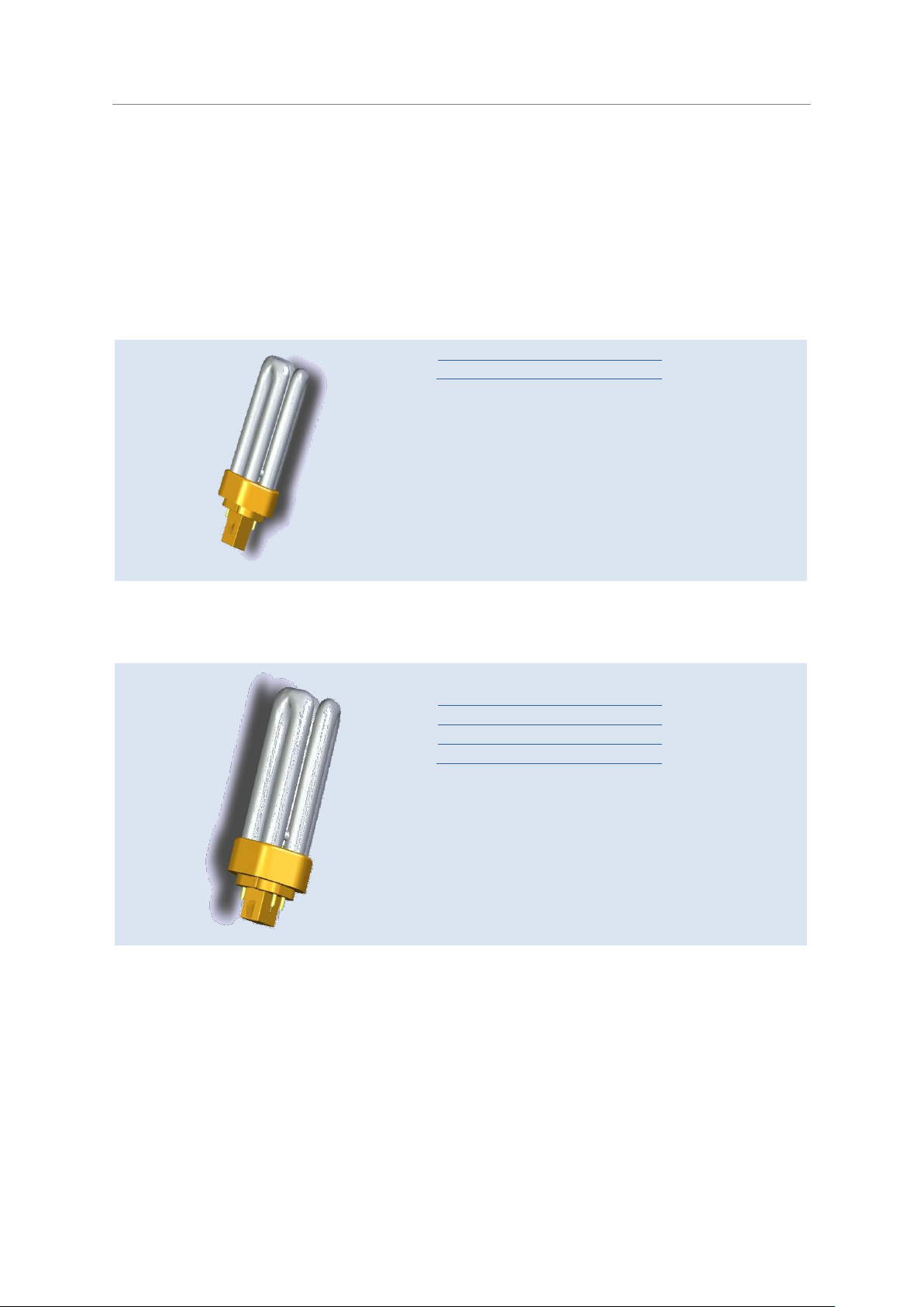
1.2.1 Lamps with integrated starter and two-pin base for conventional operation
OSRAM DULUX® S
OSRAM DULUX® S is a single-turn lamp with a 12 mm tube diameter and G23 two-pin base. The
starter components are situated in the lower section of the base. This lamp has already become a
classic and is used in a wide range of applications. Many light fittings (wall-mounted, desktop,
workplace, low-profile surface-mounted, downlight and outdoor) are built around this basic model
of the compact fluorescent lamp.
6
Page 9
Economical long-life light sources with plug-in bases
10 W
600 lm
13 W
900 lm
18 W
1200 lm
26 W
1800 lm
Light colours
LUMILUX® 827, 830, 840
With built in glow starter
Only for CCG operation
G24d, 2 pin base
Average life time: 10,000 h
Ambient temperature
25°C
30°C
16 W
1120 lm
1150 lm
23 W
1700 lm
1750 lm
Light colours
LUMILUX® 827, 830, 840,
With built in glow starter
Only for CCG operation
G24d, 2 pin base
Average life time: 10,000 h
Compact Fluorescent Lamps OSRAM DULUX®
Technical Guide
OSRAM DULUX® D
OSRAM DULUX® D is a lamp with double-turn tubes, which make it much shorter than the S version. Again, the starter components are situated in the lower section of the G24d base. These lamps
are used mainly in single or multi-lamp downlights. They can also be found in a wide variety of indoor and outdoor light fittings.
OSRAM DULUX® D ES
OSRAM DULUX® D ES 16 W and 23 W replace the standard DULUX® D 18 W and 26 W versions in
existing light fittings.
7
Page 10
Economical long-life light sources with plug-in bases
13 W
900 lm
18 W
1200 lm
26 W
1800 lm
Light colours
LUMILUX
®
827, 830, 840,
With built in glow starter
Only for CCG operation
GX24d, 2 pin base
Average life time: 13 W 3,200 h
18 W 3,900 h
26 W 10,000 h
Ambient temperature
25°C
35°C
16 W
1050 lm
1150 lm
28 W
2050 lm
2200 lm
Light colours
LUMILUX® 827, 835
With built in glow starter
For CCG operation only
GR8, 2 pin base
Average life time: 10,000 h
Compact Fluorescent Lamps OSRAM DULUX®
Technical Guide
OSRAM DULUX® T PLUS
OSRAM DULUX® T PLUS is a version with triple-turn tubes for an extremely short overall length.
The starter components are situated in the lower section of the base. The two-pin base is a GX24d
base. This type of lamp is perfect for shallow downlights and can also be used in various indoor and
outdoor light fittings.
OSRAM DULUX® T PLUS 13, 18 and 26 W can be used with lamp holder systems for OSRAM
DULUX® D 13, 18 and 26 W. The only point to remember is that the upper section of the base on the
T version is wider. OSRAM DULUX® T PLUS 13, 18 and 26 W lamps can be operated on the same
control gear as OSRAM DULUX® D 13, 18 and 26 W lamps. OSRAM DULUX® S, D, T PLUS and T
CONSTANT lamps with two-pin bases (CCG operation) are not suitable for emergency systems or
DC operation.
OSRAM CFL SQUARE® 2 pin
OSRAM CFL SQUARE® lamps are slim compact fluorescent lamps. The square shape provides
uniform distribution of light, with no shadows at either end and no dark patches. The lamps are ideal
for low-profile wall and ceiling light fittings.
OSRAM CFL SQUARE® lamps with lamp caps GR8, 2 pin base are not suited for emergency systems or DC operation.
8
Page 11
Economical long-life light sources with plug-in bases
7 W
405 lm
9 W
600 lm
11 W
900 lm
Light colours
LUMILUX® 827, 830, 840
2G7, 4 pin base
Average life time : 20,000 h for ECG operation
10 W
600 lm
13 W
900 lm
18 W
1200 lm
26 W
1800 lm
Light colours
LUMILUX
®
827, 830, 840,
G24q, 4 pin base
Average life time: 20,000 h for ECG operation
18 W
1200 lm
26 W
1800 lm
Light colours
LUMILUX
®
830, 840,
G24q, 4 pin base
Average life time: 36,000 h for ECG operation
Compact Fluorescent Lamps OSRAM DULUX®
1.2.2 Lamps with four-pin bases for operation with electronic control gear (ECG)
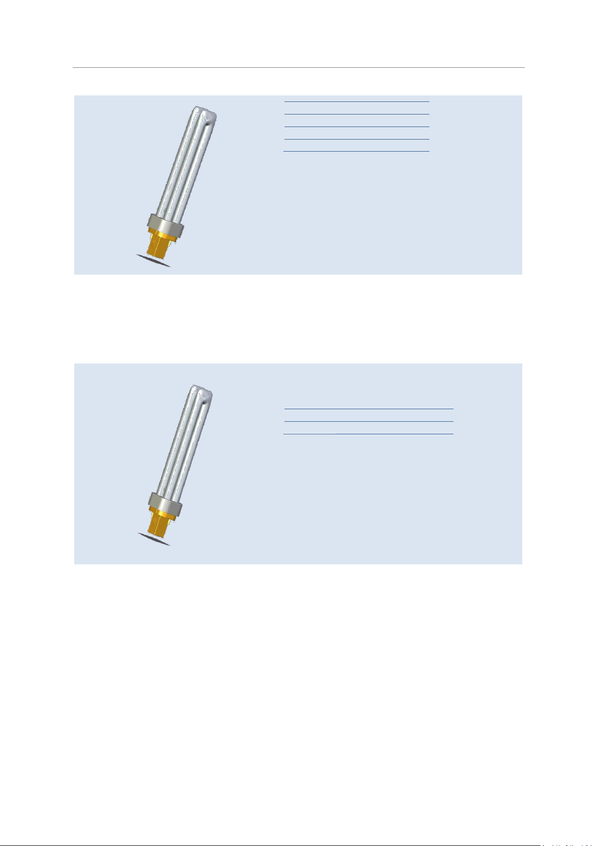
OSRAM DULUX® S/E
OSRAM DULUX® S/E are similar to OSRAM DULUX® S lamps in their design. The main differences
are the four-pin 2G7 base and the lack of an integrated glow starter. These lamps include the benefits of ECG operation, such as improved economy and more comfortable light. ECG operation
opens up new applications, notably battery operated camping light fittings and emergency lighting
(pictogram illumination).
Technical Guide
OSRAM DULUX® D/E
OSRAM DULUX
®
D/E with a G24q base is the four-pin version of the classic OSRAM DULUX® D,
designed for ECG operation. In conjunction with suitable control gear, this lamp can also be
dimmed.
OSRAM DULUX® D/E XT
9
Page 12

Economical long-life light sources with plug-in bases
13 W
900 lm
18 W
1200 lm
26 W
1800 lm
32 W
2400 lm
42 W
3200 lm
Light colours
LUMILUX® 827, 830, 840,
GX24q, 4 pin base
Average life time: 20,000* h on ECG operation
* 13,000 h for 42 W
32 W
2400 lm
42 W
3200 lm
Light colours
LUMILUX® 827, 830, 840,
GX24q, 4 pin base
Average life time: 36,000 h on ECG operation
Compact Fluorescent Lamps OSRAM DULUX®
Technical Guide
OSRAM DULUX
®
D/E XT is the long life version that extends the product range of
OSRAM DULUX® D/E lamps. Designed for ECG operation only, these lamps can also be dimmed in
conjunction with a suitable control gear.
OSRAM DULUX® T/E PLUS
OSRAM DULUX
®
T/E PLUS with a GX24q four-pin base is an extremely short lamp with the photo-
metric benefits of triple-turn tubes. Designed for ECG operation, these lamps can also be dimmed in
conjunction with a suitable control gear.
OSRAM DULUX® T/E XT
OSRAM DULUX
OSRAM DULUX
®
T/E XT is the long life version that extends the product range of
®
T/E PLUS lamps. Designed for ECG operation only, these lamps can also be
dimmed in conjunction with a suitable control gear.
1.2.3 High efficiency (HE) lamps for operation with electronic control gear (ECG):
The HE lamps have been specially designed, to guarantee more energy savings, thanks to their
higher efficiency up to 100lm/W. The High efficiency concept allows the light fitting manufacturers
to design new, more energy efficient luminaires and so to save more energy in new installations.
Compared to standard DULUX® lamps, the DULUX® HE lamps develop their light flux maximum
value at higher ambient temperatures - ca. 35°C, which is getting closer to the real conditions in a
compact down light light fitting.
The HE range uses a new designed lamp base/holder system. The lamps are not intended to be
used as direct retrofits.
10
Page 13
Economical long-life light sources with plug-in bases
Ambient temperature
25°C
35°C
11 W
810 lm
890 lm
14 W
1050 lm
1175 lm
17 W
1250 lm
1460 lm
Light colours
LUMILUX
®
830, 840
GR14q
Twist-lock, 4 pin base
Average life time: 20,000 h for ECG operation
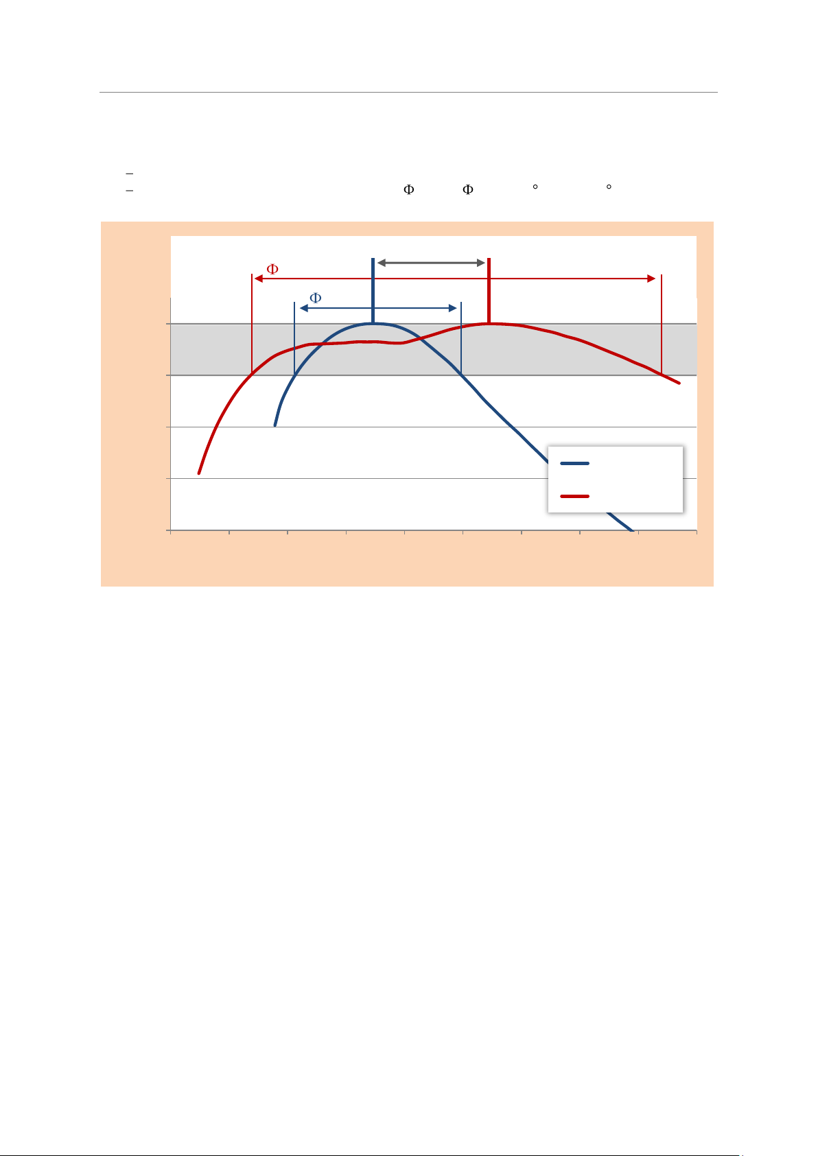
Comparison Φ( T) DULUX D/E 26W and T/E HE 17W base up
0,0
20,0
40,0
60,0
80,0
100,0
120,0
8
13
23
29
34
39
44
49
53
58
63
Ambient lamp temperature °C
Relative light flux %
DULUX T/E HE 17W
DULUX D/E 26 W
Compact Fluorescent Lamps OSRAM DULUX®
OSRAM DULUX® T/E HE
A high efficiency compact fluorescent lamp, available in three wattages:
DULUX
®
T/E 11W HE with its dimensions and light output is comparable with DULUX® D/E
13W.
DULUX
DULUX
®
T/E 14W HE is comparable with DULUX® D/E 18W.
®
T/E 17W HE is similarly comparable with the DULUX® D/E 26W.
Technical Guide
So, an energy consumption saving of more than 20% is possible, compared to a standard DULUX®
D/E lamp.
The HE technology offers the further advantage, that the lamps develop their optimum light output
at an ambient temperature range from 28°C up to 52°C.
35°C is the optimum ambient temperature for the maximum luminous flux. By contrast, standard
DULUX® D/E lamps produce maximum luminous flux at 25°C.
The lamps can only be operated in combination with suitable electronic control gear, and are dimmable in combination with the proper dimmable electronic control gear. A suitable OSRAM control
gear range is available and can be supplied together with the lamps.
11
Page 14

Economical long-life light sources with plug-in bases
Compact Fluorescent Lamps OSRAM DULUX®
Technical Guide
DULUX® T/E HE lamps have a special designed lamp base/holder system utilizing a twist and lock
installing principle. The system is shorter than the standard four-pin base system and the lamps are
much easier to install. This opens new possibilities for the design of new light fittings.
12
Page 15
Economical long-life light sources with plug-in bases
Ambient temperature
25°C
35°C
16 W
1500 lm
1600 lm
22 W
2055 lm
2200 lm
26 W
2470 lm
2600 lm
28 W
2700 lm
2800 lm
Light colours 830, 840
2GX11, 4 pin base
Average life time: 20,000 h for ECG operation
18 W
1200 lm
24 W
1800 lm
36 W
2900 lm
40 W *
3500 lm
55 W *
4800 lm
80 W *
6000 lm
* Only for ECG operation
Light colours
LUMILUX
®
827, 830, 840, 860**, 880**
** reduced luminous flux. Consult www.osram.com
2G11, 4 pin base
Average life time:
10,000 h for CCG operation
20,000 h for ECG operation
Compact Fluorescent Lamps OSRAM DULUX®
Technical Guide
OSRAM DULUX® L HE
Is a high efficiency compact fluorescent lamp with a very high energy efficiency of 100lm/W. The
lamp offers new possibilities by designing new energy and cost efficient lighting solutions.
The DULUX® L HE lamp uses a new lamp base/holder system. So it is not suitable for 1:1 retrofits.
DULUX® L HE can only be operated in combination with electronic control gear.
A suitable control gear range is available, and can be supplied together with the lamps.
1.2.4 Lamps with four-pin bases for conventional or ECG operation
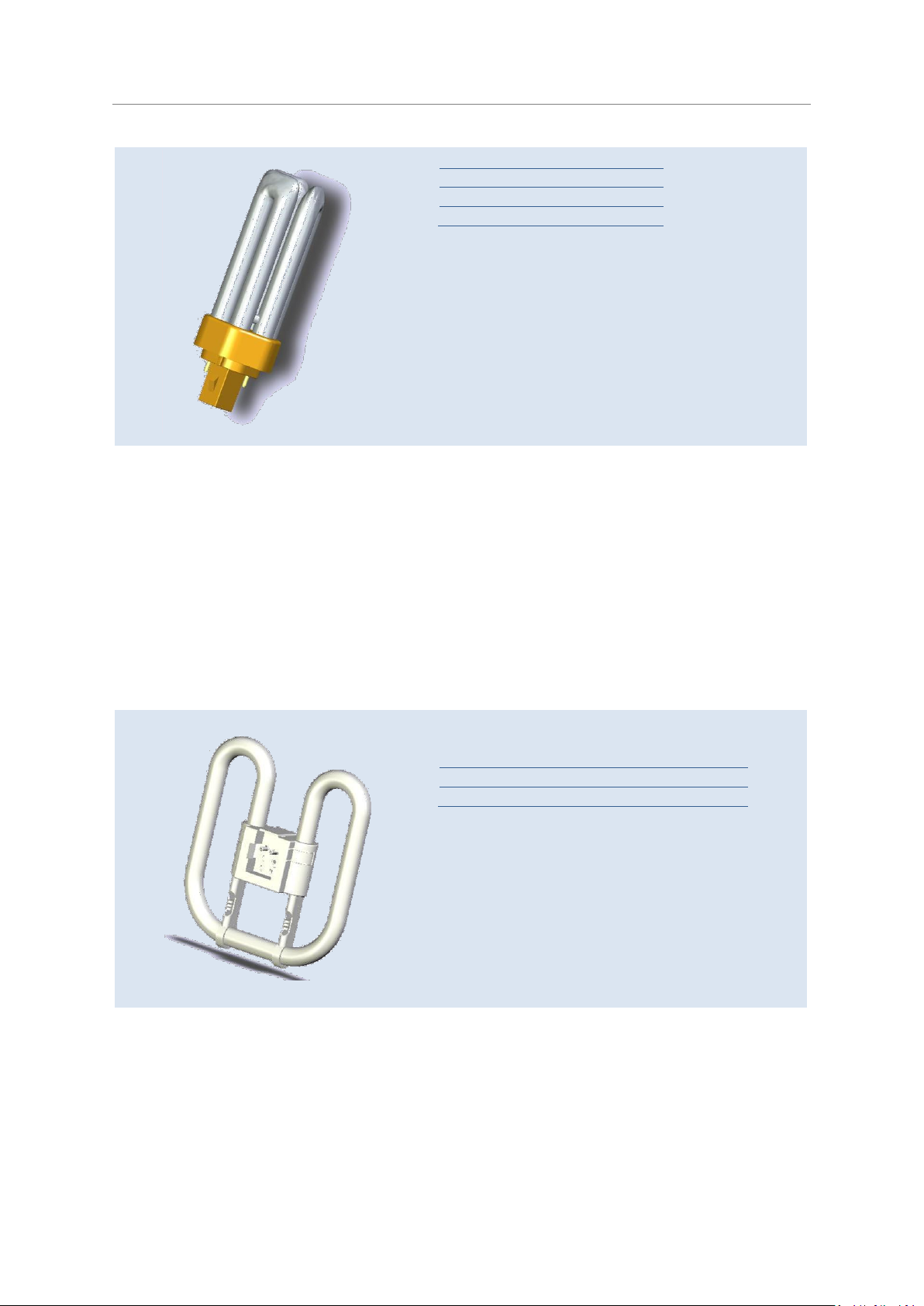
OSRAM DULUX® L
OSRAM DULUX
most the same luminous flux and power consumption as tubular fluorescent lamps but are less than
half as long and are more compact than U-shaped and ring-shaped lamps. OSRAM DULUX® L are
the ideal light source for modern space-saving wall and ceiling lighting in offices, shops, exhibition
rooms, foyers and canteens. They are also used for display and outdoor lighting.
OSRAM DULUX® L 18, 24 and 36 W lamps can be used with conventional control gear or appropriate electronic control gear, such as QUICKTRONIC®. These lamps can also be dimmed in conjunction with suitable electronic control gear.
If used with conventional control gear and external starter, a power factor correction capacitor is
needed to improve voltage current phase shift.
®
L lamps are compact fluorescent lamps with a high luminous flux. They have al-
13
Page 16
Economical long-life light sources with plug-in bases
18 W
1200 lm
24 W
1800 lm
36 W
2900 lm
55 W *
4800 lm
* Only for ECG operation
Light colours
LUMILUX
®
830, 840
2G11, 4 pin base
Average life time: 36,000 h for ECG operation
18 W
1100 lm
24 W
1705 lm
36 W
2810 lm
Light colours
LUMILUX® 827, 830, 840
2G10, 4 pin base
Average life time:
10,000 h for CCG operation
20,000 h for ECG operation
Compact Fluorescent Lamps OSRAM DULUX®
Technical Guide
OSRAM DULUX® L XT
OSRAM DULUX
®
L XT is the long life version that extends the product range of OSRAM DULUX® L
lamps. Designed for ECG operation only, these lamps can also be dimmed in conjunction with a
suitable control gear.
OSRAM DULUX® F
OSRAM DULUX
Thanks to its compact dimensions, OSRAM DULUX
®
F is a particularly low-profile compact fluorescent lamp with a high luminous flux.
®
F is the perfect lamp for area lighting with 2 M
to 3 M module light fittings (200 to 300 mm edge length) in the form of square recessed and surface-mounted light fittings or low-profile wall and ceiling light fittings.
OSRAM DULUX
®
F 18, 24 and 36 W are suitable for CCG and ECG operation. If used with conven-
tional control gear and an external starter, a power factor correction capacitor is needed to improve
voltage current phase shift.
The lamps can only be dimmed with appropriate electronic control gear such as QUICKTRONIC®.
14
Page 17
OSRAM CFL SQUARE® 4 pin
16 W
1050 lm
28 W
2050 lm
38 W
2735 lm
Light colours
LUMILUX® 827, 835
GR10q, 4 pin base
Average life time:
10,000 h for CCG operation
10,000 h for ECG operation
18 W
1200 lm
24 W
1800 lm
36 W
2900 lm
Light colours
LUMILUX® 830, 840
2G11, 4 pin base
Average life time:
10,000 h for CCG operation
20,000 h for ECG operation
The four-pin base version suitable either for electronic operation with a suitable ECG or for operation with a magnetic ballast and an external starter.
1.2.5 Lamps for special Applications:
Economical long-life light sources with plug-in bases
Compact Fluorescent Lamps OSRAM DULUX®
Technical Guide
In some cases the design of the light fitting, or the application itself, put special demands on the
lamps. The lamps may, for example, have to operate at high ambient temperatures or they may
have to ignite and operate at low ambient temperatures. There have been special lamps developed,
as well as some of the ranges of existing lamps have been modified to meet these special requirements:
OSRAM DULUX
®
L SP (four-pin base).
Amalgam lamps:
OSRAM DULUX
OSRAM DULUX
OSRAM DULUX
®
T CONSTANT (two-pin base)
®
T/E CONSTANT (four-pin base)
®
L CONSTANT (four-pin base)
OSRAM DULUX® L SP
OSRAM DULUX® L SP for outdoor lighting has been developed specifically for large volume ventilated light fittings and for cool climates. These lamps produce their maximum luminous flux at a
lower temperature than conventional compact lamps (see 4.6.3 Luminous flux/temperature graphs
for OSRAM DULUX® CONSTANT lamps, p. 64). Apart from their rounded tube ends, they are identical in construction to OSRAM DULUX® L lamps and are operated with the same conventional or
electronic control gear.
15
Page 18
Economical long-life light sources with plug-in bases
26 W
1800 lm
Light colours
LUMILUX® 827, 830, 840,
With built in glow starter
Only for CCG operation only
G24d, 2 pin base
Average life time:
10,000 h for CCG operation
26 W
1800 lm
32 W
2400 lm
42 W
3200 lm
Light colours
LUMILUX® 827, 830, 840,
GX24q, 4 pin base
Average life time:
20,000* h for ECG operation
* 13,000 h for 42 W
Compact Fluorescent Lamps OSRAM DULUX®
Technical Guide
Amalgam Lamps
OSRAM DULUX® T CONSTANT and OSRAM DULUX® T/E CONSTANT
with triple-turn tubes have been optimized for constant lumen output under variation of lamp ambient temperature, such as operation in narrow downlights in which high ambient temperatures may
occur or outdoor applications. Thanks to their special amalgam technology used, the luminous flux
remains more or less constant over a wide range of temperatures (see 4.6.2). CONSTANT lamps are
identical in construction to the OSRAM DULUX® T and T/E lamps except for their rounded tube
cross-section at the glass tube bend and a shorter discharge tube (about 5 mm shorter).
OSRAM DULUX® T CONSTANT has a two-pin GX24d base. These lamps use the same control gear
as OSRAM DULUX® D and OSRAM DULUX® T PLUS.
OSRAM DULUX® T/E CONSTANT is the four-pin version with a GX24q base. It uses the same electronic control gear as OSRAM DULUX® D/E and T/E. These lamps can be dimmed with certain restrictions (see 4.7.1 Dimming of OSRAM DULUX CONSTANT lamps, p. 67).
These lamps are not suitable for emergency lighting to DIN EN 1838.
OSRAM DULUX® T/E CONSTANT lamps, particularly the high-wattage models, can be used in outdoor light fittings of suitable dimensions.
16
Page 19
Economical long-life light sources with plug-in bases
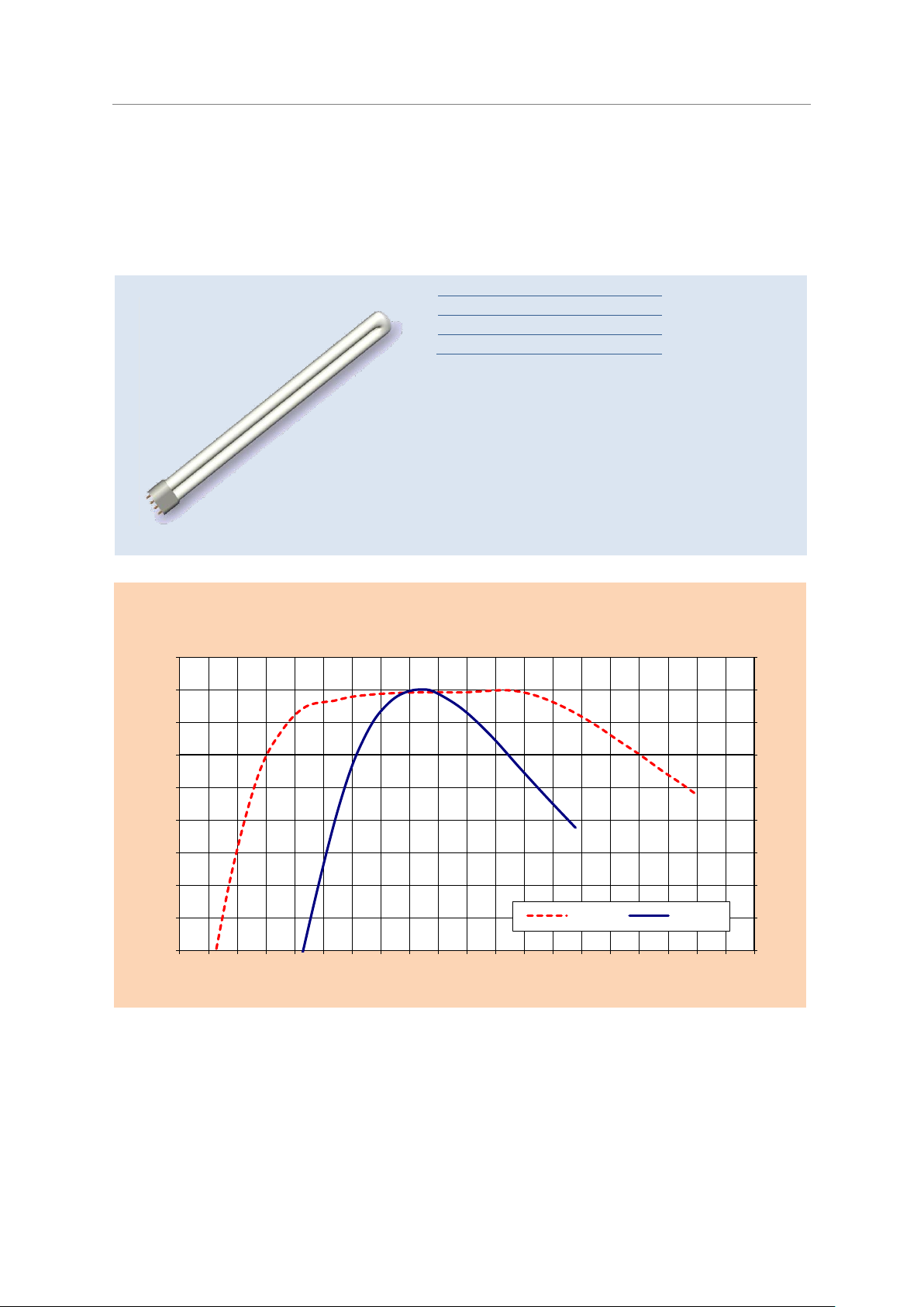
60
70
80
90
100
-10 0 10 20 30 40 50 60 70 80
Relative luminous flux [%]
Ambient lamp temperature [°C]
T/E
T/E CONSTANT
90
90
∆T = 20 C
Compact Fluorescent Lamps OSRAM DULUX®
Technical Guide
The luminous flux in relation to the ambient temperature of the DULUX® T/E and DULUX® T/E CONSTANT
Maximal light flux temperature moved by 20°C to higher temperatures
Expansion of the temperature range with > 90%
from 5 C up to 70 C
max
17
Page 20
Economical long-life light sources with plug-in bases
40 W
3500 lm
55 W
4800 lm
80 W
6000 lm
Only for ECG operation
Light colours
LUMILUX® 840
2G11, 4 pin base
Average life time:
20,000 h for ECG operation
60
65
70
75
80
85
90
95
100
105
60
65
70
75
80
85
90
95
100
105
-10 -5 0 5 10 15 20 25 30 35 40 45 50 55 60 65 70 75 80 85 90
Relative luminous flux [%]
Relative luminous flux [%]
Lamp ambient temperature [°C]
Comparision Φ(T)
DULUX L CONSTANT and DULUX L
(horizontal position)
Constant
Cold Spot
Compact Fluorescent Lamps OSRAM DULUX®
Technical Guide
OSRAM DULUX® L CONSTANT
OSRAM DULUX® L CONSTANT is a special version of the DULUX L. The DULUX L also implements
the CONSTANT technology and its advantages into the standard DULUX® L lamp type.
The DULUX® L CONSTANT is also suitable for cold, outdoor applications as for the use in light fittings with increased lamp ambient temperatures. The DULUX® L CONSTANT lamps are operated on
the same electronic control gear as the standard DULUX® L lamps.
The OSRAM DULUX
lamp.
®
L CONSTANT has the same four-pin base 2G11 as the standard DULUX L
18
Page 21
Compact Fluorescent Lamps OSRAM DULUX®
OSRAM
DULUX® T/E HE
14 W
OSRAM
DULUX® D/E
18 W
OSRAM
DULUX® D
18 W
Incandescent
Lamp
(Before ErP)
Lamp wattage
14 W
18 W
18 W
100 W
CCG losses
- - 6 W
-
ECG losses
2 W
2 W
- - Total wattage
16 W
20 W
24 W
100 W
Luminous flux
1200 lm *
1200 lm
1200 lm
1380 lm
Lamp life (average life for a 3 h
switching cycle)
20.000 h
20.000 h
10.000 h
1.000 h
Hours burned
20.000 h
20.000 h
2x10.000 h
20x1.000 h
Power consumption during 20.000
hours of operation
320 kWh
400 kWh
480 kWh
2000 kWh
Electricity costs at € 0,13/kWh
20'000 h
€ 41,6
€ 52
€ 62,4
€ 260
Savings over the life of one OSRAM
DULUX® lamp (20'000 h)
€ 218,4
€ 208
€ 197,6
Lamp
Motion
detection
Outdoor light
Cold environment
Hot environ-
ment
DC operation
EL
E-Saving
Dimming
Effect Dim-
ming
S, D, T, CFL SQUARE® 2-Pin
D ES, T CONSTANT
S/E, D/E, T/E PLUS
T/E HE,T/E XT, L HE
T/E CONSTANT
L KVG/EVG, L XT
/
/
/
/
L SP KVG/EVG
/
/
/
/
L CONSTANT
F KVG/EVG
/
/
/
/
CFL SQUARE® 4-Pin
1.3 Economy and suitability
* luminous flux at 35°C, rated luminous flux at 25°C: 1050 lm.
Special application areas for different OSRAM DULUX® lamp types
Economical long-life light sources with plug-in bases
Technical Guide
suitable
possible
not suitable
19
Page 22
Economical long-life light sources with plug-in bases
Compact Fluorescent Lamps OSRAM DULUX®
Technical Guide
1.4 Technical design and operation
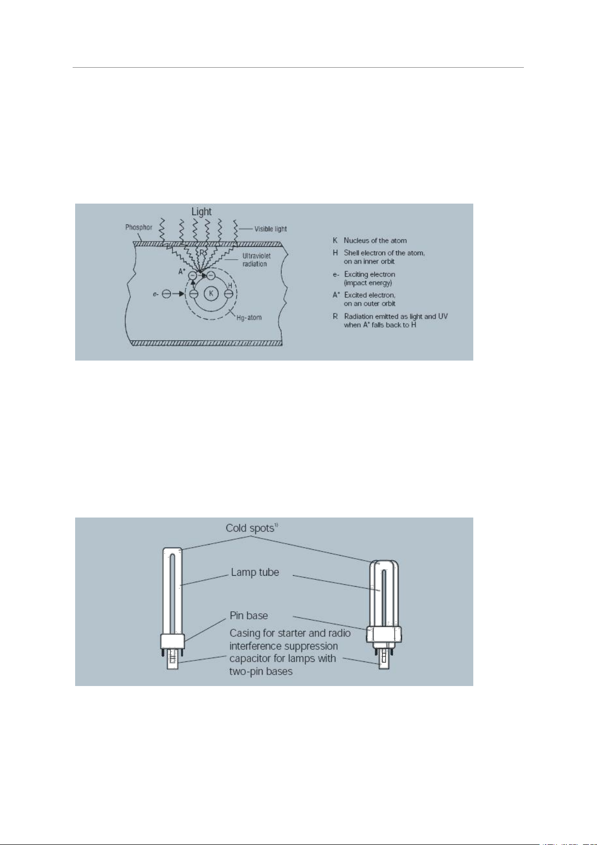
The low pressure discharge method of generating light is one of the most economic. It needs only
one quarter (or a fifth using an ECG) of the electrical energy which an incandescent lamp with the
same light output would need.
In OSRAM DULUX
sure gas discharge. Electrical current is conducted through the tube from one electrode to the
other. The electrons excite mercury atoms so that they emit optical radiation. This radiation i s converted into visible light by the tri-phosphor coating on the inner wall of the tube.
®
lamps, as in conventional fluorescent lamps, light is generated by a low-pres-
The principle of light generation in a fluorescent lamp
High luminous efficacy (the relationship between luminous flux and power consumption) is achieved
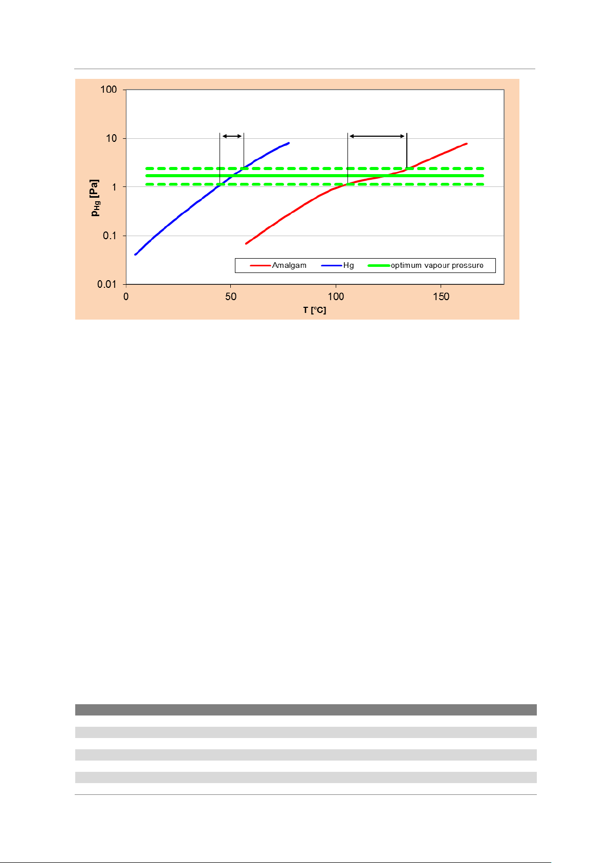
when an optimum mercury vapour pressure exists in the discharge tube. This depends on the temperatures on the inner tube wall and is regulated by the vaporisation of mercury and its condensation at the cool zones (cold spot) of the discharge tube.
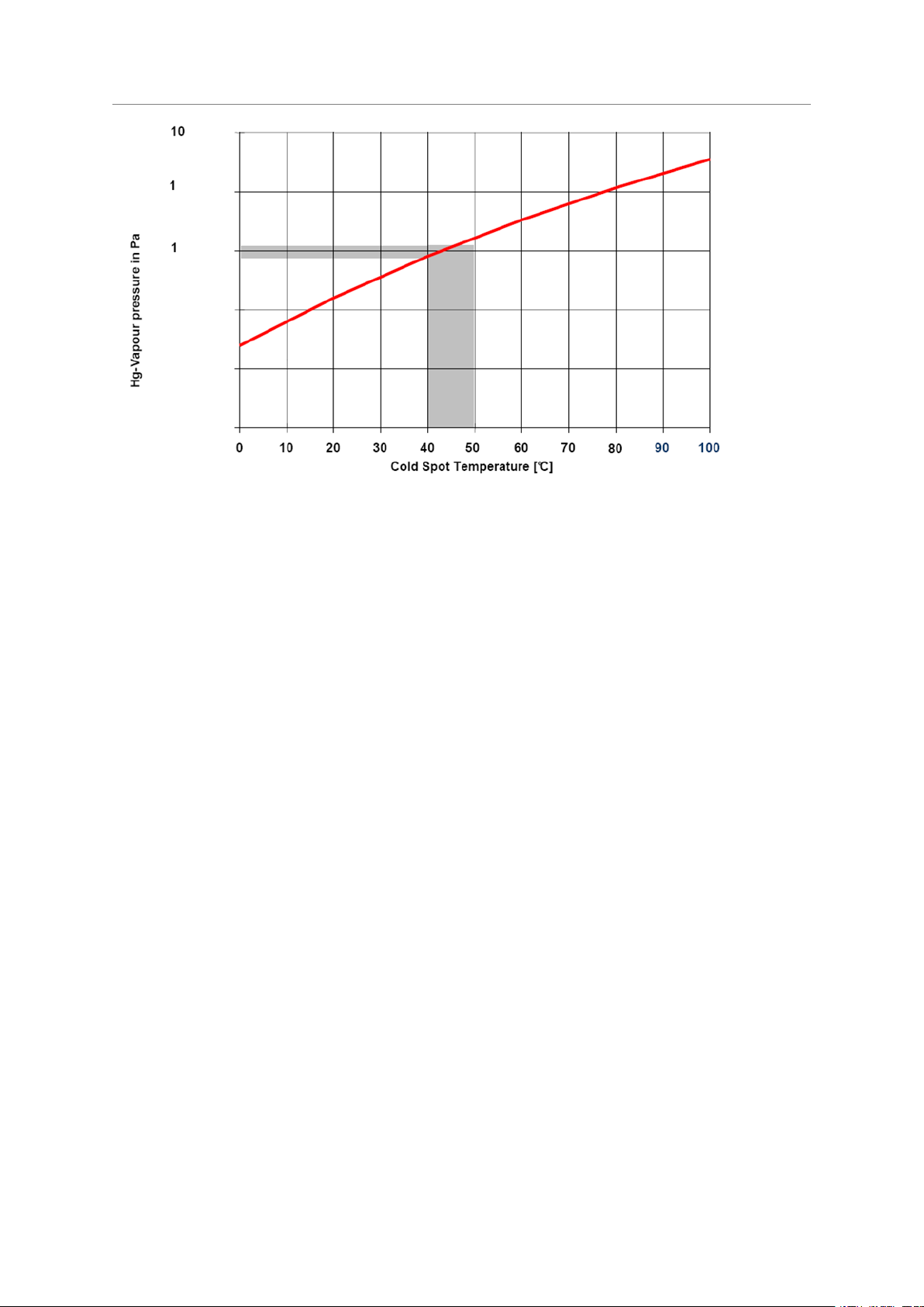
In contrast to fluorescent lamps, the corners at the top of the discharge tube on an OSRAM
DULUX
®
lamp act as cold spots. The temperature at these cold spots depends to some extent on
the burning position of the lamp and the ambient temperature.
Good conditions for luminous flux and lamp performance exist when the temperature at these cold
spots is between 40ºC and 50ºC.
Technical design of OSRAM DULUX® S and OSRAM DULUX® T PLUS
20
Page 23
Economical long-life light sources with plug-in bases
0,1
0,01
0,001
Compact Fluorescent Lamps OSRAM DULUX®
Technical Guide
Relation between cold spot temperature in a fluorescent lamp and the mercury vapour pressure in the discharge.
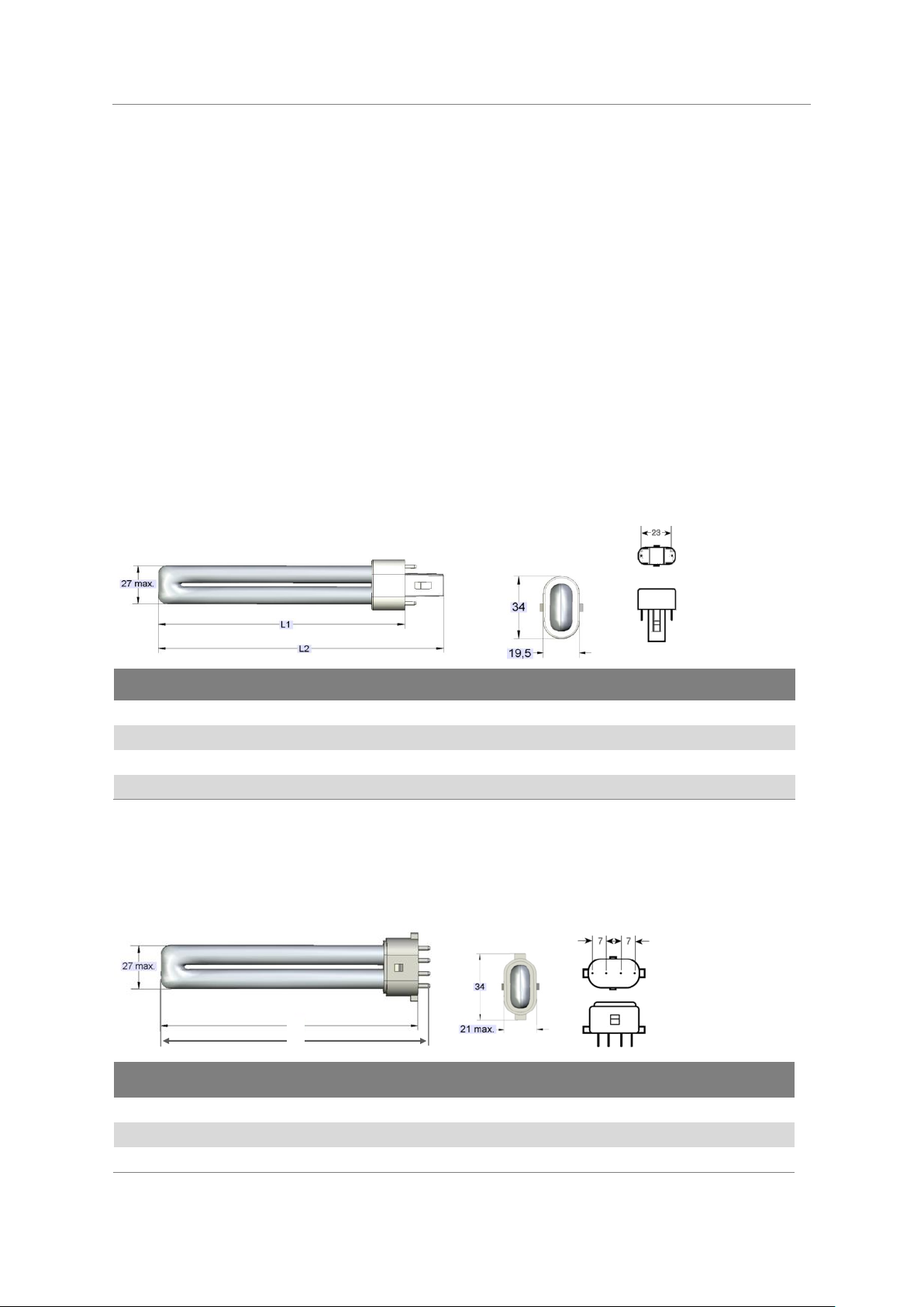
OSRAM DULUX® CONSTANT (amalgam lamps)
In contrast to standard cold spot lamps, OSRAM DULUX
®
CONSTANT (amalgam lamps) were specially designed to achieve the optimum light output over a wide ambient temperature range.
CONSTANT technology enables the use of fluorescent lamps in applications where very high or on
the other hand very low lamp-ambient temperatures prevail. Circumstances, where the cold spot
fluorescent lamp technology already suffers on a significant light flux depression.
CONSTANT lamps use amalgam and its special physical properties to control the vapour pressure
in the lamp. Amalgam is an alloy consisting of mercury and different metals such as Bi, In, Ag. The
Hg-vapour pressure (and consequently the luminous flux) is then controlled by the composition and
the temperature of the amalgam. A CONSTANT lamp does not have a cold spot like a conventional
lamp. The amalgam is located either in a tube-end tip inside of the socket, or on the framework,
mounted on one of the electrodes.
Amalgam generally needs a higher operation temperature itself, compared to the liquid Hg in a cold
spot controlled lamp. This causes a certain delay (time shift) on the run-up behaviour. In order to
shorten the run-up time of the CONSTANT lamp, a second, so called run-up amalgam flag is installed in the close vicinity of the emitter coil. The run-up amalgam is heated very quickly by the coil
and releases a certain amount of mercury to the discharge, which speeds up the run-up of the lamp
luminous flux.
The use of amalgam enables a significantly expanded temperature range with optimal Hg vapour
pressure and consequently, a lamp light output above 90% of the nominal. (See chart below).
21
Page 24
Economical long-life light sources with plug-in bases
Lamps with two-pin bases
Interference suppression capacitor [nF]
OSRAM DULUX® S 5 W, 7 W, 9 W, 11 W
3,3
OSRAM DULUX® D 10 W, 13 W
3,3
OSRAM DULUX® D 18 W, 26 W
1,2
OSRAM DULUX® D ES 16 W, 23 W
1,2
OSRAM DULUX® T PLUS 13 W
3,3
OSRAM DULUX® T PLUS 18 W, 26 W1)
1,2
OSRAM CFL SQUARE®
*
∆T Hg
∆T Am
Compact Fluorescent Lamps OSRAM DULUX®
Technical Guide
Hg-Vapour pressure in relation to the mercury (blue) and amalgam temperature (red).
The CONSTANT amalgam is an alloy with a high operation temperature and a wide homogenous
temperature range with optimum Hg-vapour pressure.
The high temperature amalgam is implemented in the OSRAM DULUX® CONSTANT lamp range like
the DULUX® L CONSTANT, DULUX® T/E CONSTANT or the T5 HO CONSTANT double-capped
fluorescent lamps, which are suitable for the use in cold and hot ambient temperature environments,
in conjunction with proper designed light fittings.
1.4.1 Radio interference suppression
Even if used with conventional control gear (50/60 Hz), gas discharge lamps generate electromagnetic radiation in the HF range. This radiation, however, has such a low energy, that radio and television transmissions are normally not affected. The HF energy is dissipated as radiation and via
cables. With an increasing distance, the radiated energy decreases so fast (1/r²), that the radiation
component about one meter from the source is lower than the level of ambient noise.
To prevent interference being carried over the cables, OSRAM DULUX® lamps with two-pin bases
have built-in interference suppression capacitors:
An interference suppression capacitor is also built into the external starter used for lamps with fourpin bases that are being operated on conventional control gear. In the case of electronic control
gear, ECG manufacturers are responsible to ensure that their products meet the relevant radio
interference suppression requirements (CISPR 15 or EN 55015). In addition, interference suppression will also depend on the way in which cables are routed in the light fitting; this factor may be
quite considerable. The light fitting manufacturer must ensure that the light fitting has adequate
radio interference suppression properties.
If an additional interference suppression capacitor is installed in the light fitting, it has to be connected parallel with the mains and not with the lamp.
1) Also for the CONSTANT versions
* In preparation
22
Page 25

Economical long-life light sources with plug-in bases
Compact Fluorescent Lamps OSRAM DULUX®
Technical Guide
1.5 Which accessories are needed for OSRAM DULUX
®
lamps?
As it is the case with fluorescent lamps, OSRAM DULUX® compact fluorescent lamps (CFLs) require
suitable control gears. A distinction is made between lamps with two-pin bases for operation on
conventional (magnetic) control gear (CCG) and lamps with four-pin bases for operation on electronic control gear (ECG).
With conventional control gear, a magnetic ballast is used to limit the lamp current and, in conjunction with the starter situated in the lower section of the base (on OSRAM DULUX® S, D and T, CFL
SQUARE® 2 pin – centre housing) to ignite the lamp. OSRAM DULUX® L, F and the OSRAM CFL
SQUARE® with four-pin base lamps, operated with conventional control, gear require an external
starter.
OSRAM DULUX® D 18 W and OSRAM DULUX® T 18 W need special conventional control gear,
adjusted to a lamp current of 220 mA. Operation of these lamps on CCG for double-capped fluorescent lamps 18 W with a lamp current of 370 mA will overload the lamps. This will cause blackening of the lamp glass in the electrode region and considerably reduce the lamp life time.
Conventional control gears (CCG) are available in different versions (e.g. with integrated lamp holder
or integrated in the mains plug). For some types of lamps, it is possible to connect two lamps in
series in conjunction with suitable control gear.
CCG operation is generally an inductive form of operation. In connection with suitable close-tolerance capacitors, capacitive operation (choke and capacitor in series) is also possible. To maintain
the prescribed operating and preheating values, close-tolerance capacitors (c.f. IEC 61049) and
chokes (c.f. IEC 60920) from renowned manufacturers are needed for series compensation – dielectric strength of the capacitors 450 V ac. However, this mode of operation is suitable only for a
few types of lamp (see 3.2).
In addition to what is generally referred to as standard control gear, the group of inductive control
gear includes low-loss gear (LLG). As their name suggests, this type of control gear is characterized
by its low power loss.
Operation of single-capped fluorescent lamps with electronic control gear (ECG), best available
technology (BAT) is a much better option. Apart from the benefits of more comfortable light, longer
lamp life and greater luminous efficacy from the system (lamp + ECG), the functions of ignition,
current limitation and compensation are all integrated in the ECG. Most ECGs are also suitable for
operation on direct current (which means they can be used in emergency lighting systems) and
comply with safety standards (automatic switch-off of failed lamps with end of lamp life detection,
etc.). There are ECG models for most single and double-lamp arrangements. Some models have an
integrated lamp holder (e.g., DULUXTRONIC®).
OSRAM DULUX® lamps are equipped with pin bases. Appropriate lamp holders are available as
standard products from all leading manufacturers in a wide variety of designs (e.g., surface -mounting and push-in lampholders for screw or clamp mounting; see 6.1).
OSRAM DULUX® L lamps need a lamp support in addition to the lampholder. Lamp supports are
optional for other OSRAM DULUX® lamps, such as the OSRAM DULUX® F (see 6.2 Lamp supports,
p. 88).
23
Page 26
Economical long-life light sources with plug-in bases
Type
Maximum length1) L1
mm
Maximum length1) L2
mm
Maximum length L1 IEC
mm
Base
OSRAM DULUX® S 5 W
85
108
85
G 23
OSRAM DULUX® S 7 W
114
137
115
G 23
OSRAM DULUX
®
S 9 W
144
167
145
G 23
OSRAM DULUX
®
S 11 W
214
237
215
G 23
Type
Maximum length1) L1
mm
Maximum length L1 IEC
mm
Maximum length L2
mm
Base
OSRAM DULUX® S/E 7 W
114
115
119
2G7
OSRAM DULUX® S/E 9 W
144
145
149
2G7
OSRAM DULUX® S/E 11 W
214
215
219
2G7
L1
L2
Compact Fluorescent Lamps OSRAM DULUX®
Technical Guide
2 Lamp data
2.1 Geometric data
Single capped lamp geometry is defined by parameters giving the diameter and the length of the
lamp. For lamp length two parameters are important to know. There is an overall length which describes the total distance from the very beginning to the end of the lamp and which is called „Over-
all length“ in this document. Sometimes it might be also called “rated overall length”. This length is
important to know to allow enough free space for lamp insertion and withdrawal in a luminaire. It
might include the length of pins if they surmount the lower lamp end or the length of a cap guide
post. The second parameter corresponds to the maximum length as it is given in IEC which lasts
from the lamp cap reference plane to the lamp top. This is called “maximum length” in this document. Sometimes it might be called “rated length” in technical specifications. This dimension de-
scribes the length of the lamp which is visible if the lamp is inserted in the holder.
2.1.1 OSRAM DULUX
1) -4mm tolerance
Base – IEC/EN60061-1, Sheet 7004-69
2.1.2 OSRAM DULUX
®
S
®
S/E
1) -4 mm tolerance
Base – IEC/EN60061-1, Sheet 7004-102
24
Page 27
Economical long-life light sources with plug-in bases
Type
Maximum length
1)
L1
mm
Maximum length
1)
L2
mm
Maximum length L1 IEC
mm
Base
OSRAM DULUX® D 10 W
87
110
95
G24 d-1
OSRAM DULUX® D 13 W
115
138
130
G24 d-1
OSRAM DULUX® D 18 W
130
153
140
G24 d-2
OSRAM DULUX® D 26 W
149
172
160
G24 d-3
Type
Maximum length1) L1
mm
Maximum length
1)
L2
mm
Maximum length L1 IEC
mm
Base
OSRAM DULUX® D ES 16 W
130
153
140
G24 d-2
OSRAM DULUX® D ES 23 W
149
172
160
G24 d-3
Type
Maximum length
1)
L1
mm
Maximum length
1)
L2
mm
Maximum length L1 IEC
mm
Base
OSRAM DULUX® D/E 10 W
87
103
95
G24 q-1
OSRAM DULUX® D/E 13 W
115
131
130
G24 q-1
OSRAM DULUX® D/E 18 W
130
146
140
G24 q-2
OSRAM DULUX® D/E 26 W
149
165
160
G 24 q-3
Compact Fluorescent Lamps OSRAM DULUX®
Technical Guide
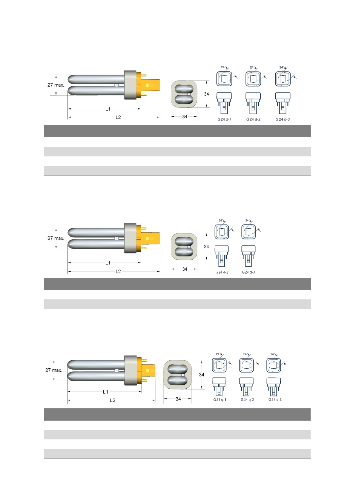
2.1.3 OSRAM DULUX
1) - 4 mm tolerance
Base – IEC/EN60061-1, Sheet 7004-78
2.1.4 OSRAM DULUX
®
D
®
D ES
1) - 4 mm tolerance
Base – IEC/EN60061-1, Sheet 7004-78
2.1.5 OSRAM DULUX
®
D/E
1) -4 mm tolerance
Base – IEC/EN60061-1, Sheet 7004-78. Same dimensions for DULUX® D/E XT versions.
25
Page 28
Economical long-life light sources with plug-in bases
Type
Maximum length1) L1
mm
Maximum length1) L2
mm
Maximum length L1 IEC
mm
Base
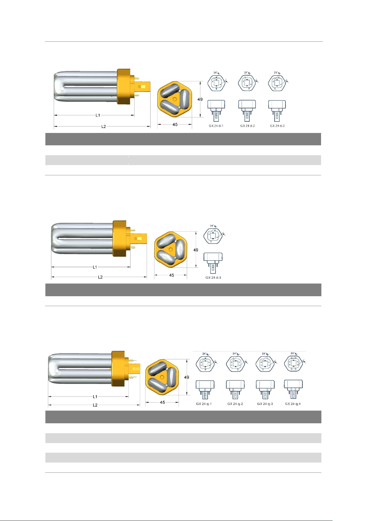
OSRAM DULUX® T PLUS 13 W
90
113
90
GX24 d-1
OSRAM DULUX® T PLUS 18 W
101
124
110
GX24 d-2
OSRAM DULUX® T PLUS 26 W
116
139
130
GX24 d-3
Type
Maximum length1) L1
mm
Maximum length1) L2
mm
Maximum length L1 IEC
mm
Base
OSRAM DULUX® T 26 W CONSTANT
112
135
130
GX24 d-3
Type
Maximum length1) L1
mm
Maximum length1) L2
mm
Maximum length L1 IEC
mm
Base
OSRAM DULUX® T/E PLUS 13 W
90
106
90
GX24 q-1
OSRAM DULUX® T/E PLUS 18 W
101
117
110
GX24 q-2
OSRAM DULUX® T/E PLUS 26 W
116
132
130
GX24 q-3
OSRAM DULUX® T/E PLUS 32 W
132
148
145
GX24 q-3
OSRAM DULUX® T/E PLUS 42 W
153
169
155
GX24 q-4
Compact Fluorescent Lamps OSRAM DULUX®
Technical Guide
2.1.6 OSRAM DULUX
1) -4 mm tolerance
Base – IEC/EN60061-1, Sheet 7004-78
2.1.7 OSRAM DULUX
®
T PLUS
®
T CONSTANT
1) - 4 mm tolerance
Base – IEC/EN60061-1, Sheet 7004-78
2.1.8 OSRAM DULUX
®
T/E PLUS
1) -4 mm tolerance
Base – IEC/EN60061-1, Sheet 7004-78
Same dimensions for DULUX® T/E XT versions.
26
Page 29
Economical long-life light sources with plug-in bases
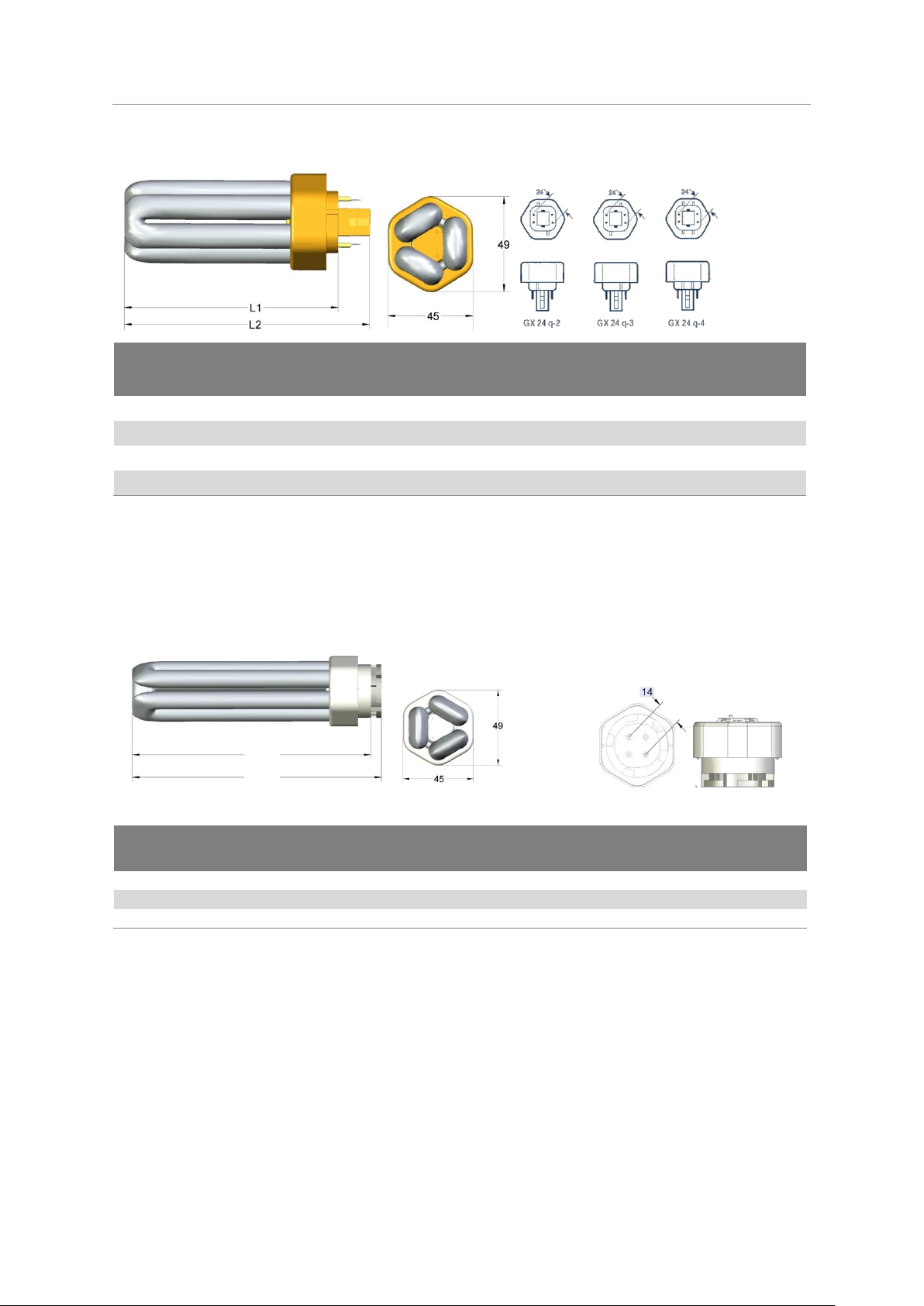
Type
Maximum length1)
L1
mm
Maximum length1)
L2
mm
Maximum length
L1 IEC
mm
Base
OSRAM DULUX® T/E 18 W CONSTANT
97
113
110
GX24 q-2
OSRAM DULUX® T/E 26 W CONSTANT
112
128
130
GX24 q-3
OSRAM DULUX® T/E 32 W CONSTANT
128
144
145
GX24 q-3
OSRAM DULUX® T/E 42 W CONSTANT
149
165
155
GX24 q-4
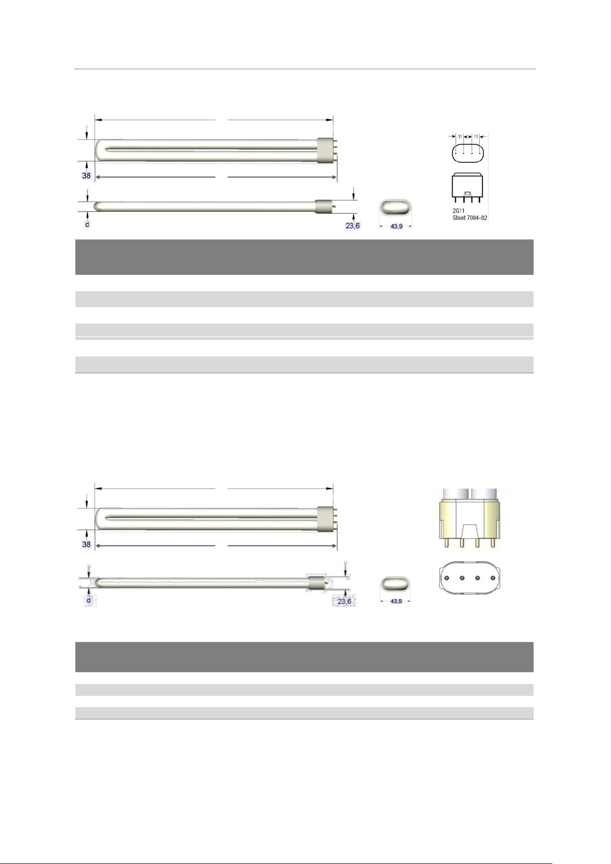
Type
Maximum length1) L1
mm
Maximum length1) L2
mm
Maximum length L2
IEC C
mm
Base
OSRAM DULUX® T/E HE 11 W
106
112
120
GR14q-1
OSRAM DULUX® T/E HE 14 W
123
129
140
GR14q-1
OSRAM DULUX® T/E HE 17 W
140
146
150
GR14q-1
l1
l2
Compact Fluorescent Lamps OSRAM DULUX®
Technical Guide
2.1.9 OSRAM DULUX
1) -4 mm tolerance
Base – IEC/EN60061-1, Sheet 7004-78
®
T/E CONSTANT
2.1.10 OSRAM DULUX
1) - tolerance -4 mm
Base – IEC/EN60061-1, Sheet 7004-157-1
®
T/E HE
GR14 q – 1:
27
Page 30
Economical long-life light sources with plug-in bases
Type
Maximum length1)
L1
mm
Maximum length
L1 IEC
mm
Maximum length
L2
mm
Tube diameter
d
mm
Base
OSRAM DULUX® L 18 W2)
217
225
222
17.5
2G11
OSRAM DULUX® L 24 W2)
317
320
322
17.5
2G11
OSRAM DULUX® L 36 W2)
411
415
416
17.5
2G11
OSRAM DULUX® L 40 W
2)3)
533
535
538
17.5
2G11
OSRAM DULUX® L 55 W
2)3)
533
535
538
17.5
2G11
OSRAM DULUX® L 80 W
2)3)
565
565
570
17.5
2G11
Type
Maximum
length1) L1
mm
Maximum
length L1 IEC
mm
Maximum
length L2
mm
Base
Corresponding geometry2)
OSRAM DULUX® L HE 16 W
317
320
322
2GX11
OSRAM DULUX® L 24 W
OSRAM DULUX® L HE 22 W
411
415
416
2GX11
OSRAM DULUX® L 36 W
OSRAM DULUX® L HE 26 W
533
535
538
2GX11
OSRAM DULUX® L 55 W
OSRAM DULUX® L HE 28 W
565
565
570
2GX11
OSRAM DULUX® L 80 W
2GX11
L1
L2
L1
L2
Compact Fluorescent Lamps OSRAM DULUX®
Technical Guide
2.1.11 OSRAM DULUX
1) – 5 mm tolerance
2) OSRAM DULUX® L lamps require a lamp support (see 6.2 Lamp supports, p. 88)
3) Same for DULUX L CONSTANT
Base – IEC/EN60061-1, Sheet 7004-82
Same dimensions for DULUX® L XT versions.
®
L
2.1.12 OSRAM DULUX
1) tolerance -5 mm
2) Information for the light fitting manufacturer
Base – IEC/EN60061-1, Sheet 7004-82A-1
®
L HE
28
Page 31

Economical long-life light sources with plug-in bases
Type
Maximum length1)
L1
mm
Maximum length
L1 IEC
mm
Maximum length
L2
mm
Tube diameter d
mm
Base
OSRAM DULUX® F 18 W
122
122
127
17.5
2G10
OSRAM DULUX® F 24 W
165
165
170
17.5
2G10
OSRAM DULUX® F 36 W
217
217
222
17.5
2G10
L1
L2
Compact Fluorescent Lamps OSRAM DULUX®
Technical Guide
2.1.13 OSRAM DULUX
1) -4 mm tolerance
Base – IEC/EN60061-1, Sheet 7004-118
®
F
29
Page 32

Economical long-life light sources with plug-in bases
Type A B C D E F
G
OSRAM CFL SQUARE® 16 W
138
141
9.9
4.5
42
33
57
OSRAM CFL SQUARE® 28 W , 38W
205
207
9.9
4.5
42
33
93
Type H I J K L M
OSRAM CFL SQUARE® 16 W
8
64
51
19
73
17.5
OSRAM CFL SQUARE® 28 W , 38W
17
74
76
39
125
22.6
I/2
I
C
A
A/2
J
B
L
3
K
3
Reference plane III
4
3
C
4
Reference plane I
Reference plane III
A
2
Reference plane II
5
D
A A
A
D
B B
G
F
H
M
M
E
Compact Fluorescent Lamps OSRAM DULUX®
Technical Guide
2.1.14 OSRAM CFL SQUARE
®
Maximum lamp outline (IEC) in mm
Base - IEC/EN 60061-1
30
Page 33

2.2 Operation modes and electrical data
Lamp reference
Rated luminous flux
lm
Rated lamp
wattage
W
Luminous
efficacy lm/W
Arc
voltage
V
Lamp
current
mA
OSRAM DULUX® S/E 7W
405
6.5
62
37
175
OSRAM DULUX® S/E 9W
600 8 75
48
170
OSRAM DULUX® S/E 11W
900
11
82
75
150
OSRAM DULUX® D/E 10W
600
9.5
63
51
190
OSRAM DULUX® D/E 13W
900
12.5
72
77
165
OSRAM DULUX® D/E 18W5)
1200
16.5
73
80
210
OSRAM DULUX® D/E 26W5)
1800
24
75
80
300
OSRAM DULUX® T/E PLUS 13W
900
12.5
72
77
165
OSRAM DULUX® T/E PLUS 18W
1) 5)
1200
16.5
73
80
210
OSRAM DULUX® T/E PLUS 26W
1) 5)
1800
24
75
80
300
OSRAM DULUX® T/E PLUS 32W
1) 5)
2400
32
75
100
320
OSRAM DULUX® T/E PLUS 42W
1) 5)
3200
43
74
135
320
OSRAM DULUX® L 18W
4) 5)
1200
16
75
50
320
OSRAM DULUX® L 24W
4) 5)
1800
22
82
75
300
OSRAM DULUX® L 36W
4) 5)
2900
32
91
90
360
OSRAM DULUX® L 40W 3)
3500
40
88
126
320
OSRAM DULUX® L 55W
3) 5)
4800
55
87
101
550
OSRAM DULUX® L 80W 3)
6000
80
75
145
555
OSRAM DULUX® F 18W
1100
16
69
50
320
OSRAM DULUX® F 24W
1700
22
77
75
300
OSRAM DULUX® F 36W
2800
32
88
90
360
OSRAM DULUX® T/E 11W HE*
810
11.4
71
80
150
OSRAM DULUX® T/E 14W HE*
1050
14.4
73
100
150
OSRAM DULUX® T/E 17W HE*
1250
17.4
72
120
150
OSRAM DULUX® L 16W HE*
1500
15.7
96
147
190
OSRAM DULUX® L 22W HE*
2055
21.4
96
147
190
OSRAM DULUX® L 26W HE*
2470
25.8
96
147
190
OSRAM DULUX® L 28W HE*
2700
27.9
97
147
190
CFL SQUARE 16W
1050
15
70
84
180
CFL SQUARE 28W
2050
24.5
84
95
260
CFL SQUARE 38W
2735
34.5
79
97
355
2.2.1 Electronic operation
Only OSRAM DULUX® lamps with four-pin bases are suitable for electronic operation.
In particular, OSRAM DULUX® L 40 W, 55 W and 80 W; OSRAM DULUX® T/E 32 W, 42 W; OSRAM
DULUX® T/E HE and L HE are approved exclusively for electronic operation.
Single-lamp and two-lamp operation are the most common arrangements for ECG operation.
The following table shows the data for reference lamps:
Measurement conditions according to IEC 60901:
Operation on reference gear
Operating frequency 25 kHz
Ambient temperature 25°C
Lamps aged for 100 hours
Base-up position for OSRAM DULUX
Horizontal position for OSRAM DULUX
Economical long-life light sources with plug-in bases
Compact Fluorescent Lamps OSRAM DULUX®
®
S/E, D/E, T/E, T/E HE, T/E CONSTANT
®
L, L HE, F, CFL SQUARE
Technical Guide
*) Values for an ambient temperature of 25°C, maximal values at ambient temperature of 35°C.
1) Also as the „CONSTANT“ version
2) Only as the „CONSTANT“ version
3) Also as the DULUX® L CONSTANT
4) Also as DULUX L SP
5) Also as XT version
31
Page 34

Economical long-life light sources with plug-in bases
Lamp
reference
Luminous
flux
lm
Lamp
Wattage
W
Luminous
efficacy
lm/W
Arc
Voltage
V
Lamp
Current
mA
Calibration
current
mA
Impedance
Power
factor
OSRAM DULUX® S 5W
257
5.4
48
35
180
170
1180
0.12
OSRAM DULUX® S 7W
405
7.1
57
47
175
170
1180
0.12
OSRAM DULUX® S 9W
600
8.7
67
60
170
170
1180
0.12
OSRAM DULUX® S 11W
900
11.8
76
91
155
170
1180
0.12
OSRAM DULUX® D 10W
600
10
60
64
190
190
1070
0.12
OSRAM DULUX® D 13W
900
13
69
91
175
165
1070
0.12
OSRAM DULUX® D 18W
1200
18
67
100
220
220
800
0.12
OSRAM DULUX® D 26W
1800
26
69
105
325
315
540
0.10
DULUX D ES 16W
1120
16
70
85
235
235
800
0,12
DULUX D ES 23W
1700
23
74
90
340
340
540
0,1
OSRAM DULUX® T PLUS 13W
900
13
69
91
175
165
1070
0.12
OSRAM DULUX® T PLUS 18W
1200
18
67
100
225
220
800
0.12
OSRAM DULUX® T PLUS 26W 2)
1800
26.5
69
105
325
315
540
0.10
OSRAM DULUX® L 18W (XT)
1200
18
67
58
375
370
540
0.10
OSRAM DULUX® L 24W (XT)
1800
24
75
87
345
340
540
0.10
OSRAM DULUX® L 36W (XT)
2900
36
81
106
435
430
390
0.10
OSRAM DULUX® F 18W
1100
18
61
56
375
370
540
0.10
OSRAM DULUX® F 24W
1700
24
71
87
345
340
540
0.10
OSRAM DULUX® F 36W
2800
36
78
106
435
430
390
0.10
OSRAM CFL SQUARE® 16W
1050
16
66
103
195
195
890
0,12
OSRAM CFL SQUARE® 28W
2050
28
73
108
320
320
480
0,1
OSRAM CFL SQUARE® 38W
2735
38.5
71
110
430
430
390
0,1
Compact Fluorescent Lamps OSRAM DULUX®
Technical Guide
2.2.2 Inductive operation Single-lamp circuit
Measurement conditions according to IEC 60901:
220 V / 50 Hz supply voltage1)
Operation on reference gear
Ambient temperature 25°C
Lamps aged 100 hours
Base-up position for OSRAM DULUX
Horizontal position for OSRAM DULUX
®
S, D, T PLUS
®
L, F and CFL SQUARE
®
1) In accordance with IEC 60901, measurements are taken at 220 V/50 Hz on the reference control gear. However, there is no change in the
electrical lamp data for 230 V and 240 V supplies, provided suitable control gear is used.
2) Also for T CONSTANT
32
Page 35

2.2.3 Inductive operation Series circuit
Lamp
reference
Luminous
flux
lm
Lamp
Wattage
W
Luminous
efficacy
lm/W
Arc
Voltage
V
Lamp
current
mA
Calibra-
tion
current
mA
Impe-
dance
Power
factor
2x DULUX® S 5W
515
11 - 35
180
170
1070
0.12
2x DULUX® S 7W
820
13.7 - 47
160
170
1070
0.12
2x DULUX® S 9W
950
14.4 - 60
130
170
1070
0.12
2x DULUX® L 18W (XT)
2500
38 - 58
425
370
390
0.12
2x DULUX® F 18W
2300
38 - 56
425
370
390
0.12
Series circuits (tandem circuits) are possible only for certain types of lamps in which the arc voltage
does not exceed certain values (see 3.2.1 Permissible lamp/CCG combinations and system data,
p. 47).
Measurement conditions according to IEC 60901:
220 V / 50 Hz supply voltage1)
Operation on reference gear
Ambient temperature 25°C
Lamps aged 100 hours
Base-up position for OSRAM DULUX
Horizontal position for OSRAM DULUX
®
S
®
L, F
Economical long-life light sources with plug-in bases
Compact Fluorescent Lamps OSRAM DULUX®
Technical Guide
1) In accordance with IEC 60901, measurements are taken at 220 V/50 Hz on the reference control gear. However, there is no change in the
electrical lamp data for 230 V and 240 V supplies, provided suitable control gear is used.
2.2.4 Inductive operation Lead-lag circuit
With certain lamps in two-lamp inductive arrangements, a lead-lag circuit can be set up in which
one of the two CCGs is combined with a series capacitor. For the capacitor data see 3.2.2
Compensation.
Circuit diagram available at www.osram.com.
33
Page 36

Economical long-life light sources with plug-in bases
Light colour
Colour temperature
Daylight
> 5000 K
Cool White
3300 - 5000 K
Warm White
< 3300 K
Ra value
Group
(according to EN 12464-1)
Characteristic
90 - 100
1A
Very good
80 - 89
1B
Very good
70 -79
2A
Good
60 - 69
2B
Good
40 - 59
3
Satisfactory
20 - 39
4
Unsatisfactory
Compact Fluorescent Lamps OSRAM DULUX®
Technical Guide
2.3 Photometric data
2.3.1 Light colours
The light colours of the lamps are divided into three groups, each covering a particular colour temperature range.
The light colour is determined by the x and y coordinates in the chromaticity table. For practical
purposes, it is important to know the colour rendering properties of the lamps in addition to their
light colour and colour temperature. These properties are defined by the (general) colour rendering
index Ra.
The colour rendering index (computed using the CIE method) provides an indication of how nonluminous colours will appear when illuminated by the relevant light source.
Colour rendering is assessed by comparison with a Planckian radiator (< 5000 K) and normalised
daylight (> 5000 K) of the same colour temperature. By definition, these radiators have the ideal
colour rendering index of 100. Any deviation from this ideal is rated with values lower than 100.
The general colour rendering index Ra is the average value of eight different internationally standardised test colours (CIE).
There are various ranges for the Ra value, known as colour rendering groups:
Note:
The colour perception of a non-luminous colour therefore always depends on the colour temperature of the illuminating lamp and colour rendering properties of this lamp.
Example:
Blue tones will always appear brighter in the light from a lamp with a daylight colour than in the light
from a lamp with a warm white colour, even if both lamps have an Ra value of 100.
OSRAM DULUX
®
single-capped fluorescent lamps are available in LUMILUX® and LUMILUX® DE
LUXE light colours. The most economical lighting is achieved with LUMILUX®. These light colours
fall into colour rendering group 1B, which means they are ideal for most applications (including
office and shop lighting, hotel and restaurant lighting, living rooms and outdoors). In places where
colour rendering is a particular important factor (e.g., art galleries, museums, laboratories and
graphical trades), OSRAM DULUX
®
lamps are also supplied in LUMILUX® DE LUXE light colours.
As group 1A lamps, these offer the best colour rendering. However, their luminous flux is lower than
their LUMILUX
Ultimately, the choice of light colour depends on the specific application, room conditions and personal preference.
34
®
counterparts; therefore more lamps are needed to achieve the same lighting level.
Page 37

2.3.2 Colour specifications
Light colour
Reference
Colour
Temperature
K
Colour rendering
Group
EN 12464-1
Colour rendering
index CRI
Ra
LUMILUX® DE LUXE
950
LUMILUX® DE LUXE Daylight
5400
1A
≥ 90
940
LUMILUX® DE LUXE Cool White
3800
1A
≥ 90
930
LUMILUX® DE LUXE Warm White
3000
1A
≥ 90
LUMILUX®
880
LUMILUX® Skywhite
8000
1B
80…89
865
LUMILUX® Daylight
6500
1B
80…89
840
LUMILUX® Cool White
4000
1B
80…89
830
LUMILUX® Warm White
3000
1B
80…89
827
LUMILUX INTERNA®
2700
1B
80…89
Special light colours1)
60
Red - - - 66
Green
- - -
67
Blue - -
-
Economical long-life light sources with plug-in bases
Compact Fluorescent Lamps OSRAM DULUX®
Technical Guide
1) Lamps with chromaticity coordinates that do not lie in the vicinity of the reference radiators (Judd lines; see
CIE calculation method) cannot, by definition, be assigned a colour temperature and hence cannot be assigned
a colour rendering index.
2.3.3 Chromaticity coordinates tolerance fields
Chromaticity coordinates tolerance fields are ellipses in the chromaticity table which represent the
permissible range for the relevant light colour. The tolerances are five threshold units for all light
colours (LUMILUX®, LUMILUX
A threshold unit represents the minimum perceivable difference in colour between two lamps (see
also IEC 60901 and IEC 60081).
®
DE LUXE).
35
Page 38

Economical long-life light sources with plug-in bases
Type
Luminous flux (lm) for light colour
LUMILUX®
LUMILUX® DE LUXE
SPECIAL LIGHT COLOURS
880
SKY-
WHITE
865
Cool
Daylight
840
Cool
White
830
Warm
White
827
INTER-
NA
950
Daylight
940
Cool
White
930
Warm
White
60
Red
66
Green
67
Blue
OSRAM DULUX® S 5W
257
257
257
OSRAM DULUX® S 7W
385
405
405
405
OSRAM DULUX® S 9W
565
600
600
600 400
800
200
OSRAM DULUX® S 11W
855
900
900
900
OSRAM DULUX® S/E 7W
405
405
405
OSRAM DULUX® S/E 9W
600
600
600
OSRAM DULUX® S/E 11W
900
900
900
OSRAM DULUX® D 10W
600
600
600
OSRAM DULUX® D 13W
900
900
900
OSRAM DULUX® D 18W
1200
1200
1200
OSRAM DULUX® D 26W
1800
1800
1800
OSRAM DULUX® D ES 16W
1120
1120
1120
OSRAM DULUX® D ES 23W
1700
1700
1700
OSRAM DULUX® D/E 10W
600
600
600
OSRAM DULUX® D/E 13W
900
900
900
OSRAM DULUX® D/E 18W 3)
1200
1200
1200
OSRAM DULUX® D/E 26W 3)
1800
1800
1800
OSRAM DULUX® T PLUS 13W
900
900
900
OSRAM DULUX® T PLUS 18W
1200
1200
1200
OSRAM DULUX® T PLUS 26W1)
1800
1800
1800
OSRAM DULUX® T/E PLUS 13W
900
900
900
OSRAM DULUX® T/E PLUS 18W1) 3)
1200
1200
1200
OSRAM DULUX® T/E PLUS 26W1) 3)
1800
1800
1800
OSRAM DULUX® T/E PLUS 32W1) 3)
2400
2400
2400
OSRAM DULUX® T/E PLUS 42W1) 3)
3200
3200
3200
OSRAM DULUX® T/E 11W HE 2)
810
810 OSRAM DULUX® T/E 14W HE 2)
1050
1050 OSRAM DULUX® T/E 17W HE 2)
1250
1250
OSRAM DULUX® L 18W 3)
1200
1200
1200
750
750
750
OSRAM DULUX® L 24W 3)
1800
1800
1800
1200
1200
1200
550
OSRAM DULUX® L 36W 3)
2610
2755
2900
2900
2900
2030
2320
2320
OSRAM DULUX® L 40W
1)
3000
3325
3500
3500
3500
2350
OSRAM DULUX® L 55W 1) 3)
4100
4550
4800
4800
4800
3000
3610
3610 OSRAM DULUX® L 80W 1)
5600
6000
6000
6000
OSRAM DULUX® L 16W HE
1500
1500
OSRAM DULUX® L 22W HE
2055
2055 OSRAM DULUX® L 26W HE
2470
2470 OSRAM DULUX® L 28W HE
2700
2700
Compact Fluorescent Lamps OSRAM DULUX®
Technical Guide
2.3.4 OSRAM DULUX
®
light colours
36
Page 39

Economical long-life light sources with plug-in bases
Type
Luminous flux (lm) for light colour
LUMILUX®
LUMILUX® DE LUXE
SPECIAL LIGHT COLOURS
880
SKY-
WHITE
865
Cool
Daylight
840
Cool
White
830
Warm
White
827
INTER-
NA
950
Daylight
940
Cool
White
930
Warm
White
60
Red
66
Green
67
Blue
OSRAM DULUX® L 18W SP
1200
1200 OSRAM DULUX® L 24W SP
1800
1800
OSRAM DULUX® F 18W
1100
1100
1100
OSRAM DULUX® F 24W
1705
1705
1705
OSRAM DULUX® F 36W
2810
2810
2810
CFL SQUARE® 16W
1050*
1050
CFL SQUARE® 28W
2050*
2050
CFL SQUARE® 38W
2735*
2735
Compact Fluorescent Lamps OSRAM DULUX®
*) Light colour 3500K
1) Also for CONSTANT models
2) Values for an ambient temperature of 25°C, maximum values at ambient temperature of 35°C
3) Also valid for XT models
Technical Guide
2.3.5 Factors affecting colour consistency
There are a number of factors that affect colour consistency and the perception of the light colour of
compact fluorescent lamps.
Iridescence
Iridescence is a property of some anodised reflector finishes which results in a „rainbow“ effect
when use in conjunction with tri-chrome phosphors. Since all OSRAM DULUX
chrome phosphors, this effect caused by the reflector may be wrongly ascribed to the lamps as
„different light colours“.
Ambient temperature
The light colour of tri-chrome phosphors changes slightly as the ambient temperature changes
because of the relationship between luminous flux and temperature. This is apparent in applications
in which, say, open ceiling light fittings are installed close to air-condition outlets. In such cases, the
light colour may be slightly different from that of luminaires located further away. This effect can be
minimised by coordinating the air-conditioning system with the lighting system.
Manufacturing tolerances
There may be minimal differences in the light colours of lamps from different manufacturers. In
applications in which colour consistency is a critical factor, all the lamps in a particular zone should
come from the same manufacturer and should all be replaced together. If lamps are replaced indi vidually there may be differences in light colour.
®
lamps contain tri-
Dimming
When fluorescent lamps are dimmed there is a slight reduction in colour temperature. The colour
temperature of a fully dimmed OSRAM DULUX
®
L 36 W lamp, for example, is around 150 K lower
than that of an undimmed lamp. The colour difference appears greater to the eye due the considerable differences in luminance. Even greater differences may occur temporarily if there is a sharp
change in the dimmer setting (see 4.7 and 5.1.4).
37
Page 40

Economical long-life light sources with plug-in bases
Light Colour 60 – Red
Compact Fluorescent Lamps OSRAM DULUX®
Technical Guide
Ageing
Generally speaking, there are no changes in colour temperature or shifts in chromaticity coordinates
in the course of a lamp’s service life. However, lamps do suffer a drop in luminous flux as they age
(see 2.4) and it is the resulting difference in luminance between an old lamp and a new lamp that
gives the impression of a change in colour temperature.
2.3.6 Spectral distribution
The relative spectral power distribution is determined mainly by the light colour, whereas the differ ent models and wattages have a negligible effect.
The spectral distributions shown below are therefore typical of all OSRAM DULUX
relevant light colour (relative values).
®
lamps for the
-
The spectral irradiance distributions refer to an illuminance of 1000 lx. The advantage here is that
the absolute values of any illuminance can be found simply by dividing by 1000 lx:
The spectral intensities are condensed into wavelength ranges of 5 nanometres. In other words,
irrespective of the actual distributions, the values given have been integrated over 5 nm. This corresponds to the standard applied to all calculations of consequential results (such as colour and colour rendering).
The spectral power distribution of OSRAM DULUX LUMILUX
®
and LUMILUX® DE LUXE lamps can
be found in the latest edition of the Lighting Program.
Light colours
38
Page 41

Economical long-life light sources with plug-in bases
Light colour 66 – Green
Light colour 67 - Blue
Compact Fluorescent Lamps OSRAM DULUX®
Technical Guide
2.3.7 Radiation components in the ultra-violet range:
Ultra-violet radiation can have desirable effects (e.g., tanning) and undesirable ones (e.g., sunburn)
on the human body. The intensity of these effects depends on the irradiance level and the period of
exposure.
In the case of lamps intended for general lighting applications, lamp and light fitting manufacturers
must ensure that there is no possibility of any harmful effects even under high illuminance levels
over a full day.
All OSRAM DULUX® lamps comply with the safety limits of UV and Blue light components set by the
IEC 62471 Safety Standard – Photo-biological Safety of Lamps and Lamp Systems.
For spectral radiation values, consult www.osram.com
If light-sensitive materials are exposed to this light for relatively long periods, there may be some
change in colour (e.g., bleaching). In OSRAM DULUX
radiation. Lamps with low UV-A components or low illuminance levels should therefore be chosen
for illuminating light-sensitive materials.
®
lamps this effect is caused primarily by UV-A
39
Page 42

Economical long-life light sources with plug-in bases
Compact Fluorescent Lamps OSRAM DULUX®
Technical Guide
2.3.8 Radiation components in the infra-red range
Fluorescent lamps emit radiation at wavelengths which are also used for infra-red transmissions.
Since the IR receivers used for televisions, wireless headphones and sound transmission systems,
for example, are often not sufficiently selective there may be interference in the IR system, particularly with lamps operated by electronic control gear, if light or optical radiation from the lighting
system enters the IR receiver. The light emitted by a fluorescent lamp is essentially modulated at
twice the operating frequency (50 to 250 kHz in the case of electronic control gear and 100 or 120
Hz in the case of conventional control gear). Interference may occur if the useful signal is also operating in this frequency range.
Audio transmission
For further information on this topic please consult the OSRAM QUICKTRONIC® technical guides or
visit www.osram.com/quicktronic.
IR remote control
Interference-free operation is possible with systems that work with a sufficiently high carrier frequency (400 to 1500 kHz). If interference occurs in systems or equipment operating at a lower car rier frequency, it is best to move the IR receiver as far as possible away from the radiation footprint
of the lamp or shield it from direct light.
For further information on this topic please consult the OSRAM QUICKTRONIC
®
technical guides or
visit www.osram.com/quicktronic.
Electronic merchandise security systems
In many shops nowadays, merchandise such as CDs and clothing is protected against theft by
electronic security systems. These systems typically operate with resonances in the kHz range. If
the operating frequency is between 30 kHz and 150 kHz it may lead to interference. Such interference can be avoided by increasing the distance between the light fittings and the transmitting/receiving system.
For further information on this topic please consult the OSRAM QUICKTRONIC
®
technical guides or
visit www.osram.com/quicktronic.
40
Page 43

2.3.9 Luminous intensity distribution charts
The luminous intensity distributions of OSRAM DULUX® lamps depend on the plane in which measurements are taken. For assessment and planning purposes, it is therefore not sufficient simply to
consider the average of all planes. Measurements of the luminous intensity distribution in three
selected planes are adequate.
Economical long-life light sources with plug-in bases
Compact Fluorescent Lamps OSRAM DULUX®
Technical Guide
OSRAM DULUX
®
S, OSRAM DULUX® S/E, OSRAM DULUX® L, L SP, L XT and L HE Axial and radial
luminous intensity distribution referred to 1000 lm, Base-up position
OSRAM DULUX® D, D ES, OSRAM DULUX® D/E and D/E XT Axial and radial luminous intensity
distribution referred to 1000 lm, Base-up position
41
Page 44

Economical long-life light sources with plug-in bases
Compact Fluorescent Lamps OSRAM DULUX®
Technical Guide
OSRAM DULUX® T PLUS, T CONSTANT, OSRAM DULUX® T/E PLUS, T/E XT, T/E HE and T/E
CONSTANT Axial and radial luminous intensity distribution referred to 1000 lm, Base-up position.
OSRAM DULUX® F, Axial and radial luminous intensity distribution referred to 1000 lm, Base-up
position
42
Page 45

Economical long-life light sources with plug-in bases
Lamp Average luminance
1)
cd/cm
2
OSRAM DULUX® S 5W
2.5
OSRAM DULUX® S and S/E 7W
2.6
OSRAM DULUX® S and S/E 9W
2.8
OSRAM DULUX® S and S/E 11W
2.7
OSRAM DULUX® D and D/E 10W
4.0
OSRAM DULUX® D and D/E 13W
4.0
OSRAM DULUX® D and D/E 18W 3)
4.5
OSRAM DULUX® D and D/E 26W 3)
5.5
OSRAM DULUX® D ES 16W
4.3
OSRAM DULUX® D ES 23W
4.3
OSRAM DULUX® T PLUS and T/E PLUS 13W
4.2
OSRAM DULUX® T PLUS and T/E PLUS 18W 3)
4.7
OSRAM DULUX® T PLUS and T/E PLUS 26W2) 3)
6.0
OSRAM DULUX® T/E PLUS 32W2) 3)
6.5
OSRAM DULUX® T/E PLUS 42W2) 3)
7.0
OSRAM DULUX® T/E 11W HE
2.9
OSRAM DULUX® T/E 14W HE
2.9
OSRAM DULUX® T/E 17W HE
2.9
OSRAM DULUX® L 18W 3)
2.1
OSRAM DULUX® L 24W 3)
2.1
OSRAM DULUX® L 36W 3)
2.8
OSRAM DULUX® L 40W2)
2.3
OSRAM DULUX® L 55W2) 3)
3.2
OSRAM DULUX® L 80W2)
3.2
OSRAM DULUX® L 16W HE
in preparation
OSRAM DULUX® L 22W HE
in preparation
OSRAM DULUX® L 26W HE
in preparation
OSRAM DULUX® L 28W HE
1.9
OSRAM DULUX® F 18W
2.4
OSRAM DULUX® F 24W
2.5
OSRAM DULUX® F 36W
3.0
CFL SQUARE® 16W
in preparation
CFL SQUARE® 28W
in preparation
CFL SQUARE® 38W
in preparation
Compact Fluorescent Lamps OSRAM DULUX®
Technical Guide
2.3.10 Luminance of OSRAM DULUX
®
lamps
1) For colours 840 LUMILUX® Cool White, 835 LUMILUX
2) Also for CONSTANT models
2) Also for XT models
®
Cool White, 830 LUMILUX
®
Warm White and 827 LUMILUX INTERNA®
43
Page 46

Economical long-life light sources with plug-in bases
OSRAM DULUX® lamps
Average rated lamp life (B50)
OSRAM DULUX® D/E XT, T/E XT, L XT with ECG (BAT)
36,000 h
OSRAM DULUX® S/E, D/E, T/E PLUS*, T/E HE, T/E CONSTANT*, L, L HE,
L CONSTANT and F with ECG (BAT)
20,000 h
OSRAM DULUX® S, D, D ES, T PLUS*, T CONSATNT and F with CCG
10,000 h
CFL SQUARE® with ECG (BAT) or CCG
10,000 h
Compact Fluorescent Lamps OSRAM DULUX®
Technical Guide
2.4 Lamp life and maintenance
2.4.1 Definitions
There are several definitions of lamp life, which are applied differently depending on the type of
lamp, the lamp manufacturer and the geographical region. The most important definitions for compact fluorescent lamps are given below.
Lamp life is the period of time during which a lamp can be operated until it is unusable (electrical
failure, light loss / insufficient light output).
Average rated lamp life (B50) is the average value of the life values of individual lamps operated
under standardized conditions (50 % failure). In other words, this is the operation time at which for a
standardized 3-hour switching cycle (165 minutes on/15 minutes off in accordance with IEC 60901)
50 % of a sample population of lamps have failed.
* Different lifetime for single lamps: T/E PLUS & T/E CONSTANT 42W: 13,000 h, T PLUS 13W: 3,200 h, T PLUS 18W: 3,900 h
Because chemical changes in the phosphor during the lamp life, the luminous flux of the lamp decreases as the lamp ages. The term “maintenance” is used to indicate how well the luminous flux is
retained throughout the life of the lamp.
2.4.2 Maintenance for OSRAM DULUX
®
lamps
For further information, please consult http://catalog.myosram.com.
2.4.3 Mortality charts of OSRAM DULUX
®
lamps
For further information, please consult http://catalog.myosram.com.
2.4.4 Effect of switching operations on lamp life
Average rated lamp life in CCG or ECG operation is based on a switching cycle of 165 minutes on
and 15 minutes off in accordance with IEC 60901.
In CCG operation, if there are fewer switching operations than under these standard conditions,
average rated lamp life will be increased. If, however, the lamp is switched on and off more often, it
will not last as long.
If an electronic control gear designed for pre-heat start according to IEC 60901 is used, the number
of possible switching operations is greatly increased compared to operation with a CCG, due to an
optimum electrode preheating.
44
Page 47

Economical long-life light sources with plug-in bases
Compact Fluorescent Lamps OSRAM DULUX®
Technical Guide
Note: Using a warm start designed ECG build upon an older technology, it is possible that after the
lamps have been switched off, it is necessary to wait a certain time, before switching on the lamps
again, to ensure a reliable warm restart of the lamps (see ECG specifications).
In any case, using the modern types of ECG, best available technology (BAT), it is not necessary to
wait a certain time anymore, there is no restriction on switching cycles or switching off time periods
affecting the lamp life, under normal operation conditions.
If an electronic control gear designed for an instant start is used, the number of possible switching
cycles is strongly decreased compared to an operation with warm start ECG. For an operation with
instant start ECG, a maximum of 2 switching cycles per day is recommended, without affecting the
lamp life.
45
Page 48

Economical long-life light sources with plug-in bases
Compact Fluorescent Lamps OSRAM DULUX®
Technical Guide
3 Circuits
3.1 Operation with electronic control gear (ECG)
OSRAM DULUX® S/E, D/E, and T/E PLUS with four-pin bases, T/E HE, XT and CONSTANT lamps
and OSRAM DULUX® L 40, 55 W and 80 W lamps (including XT and CONSTANT types) have been
designed to operate with electronic control gear only. OSRAM DULUX® L and F 18, 24, 36 W and
the CFL SQUARE® four-pin can be operated with either electronic or magnetic control gear.
To ensure safe operation of both, the lamp and the ECG, the wiring between the outputs of the ECG
and the terminals on the lamp holder(s) must be correct. This applies not only to two-lamp arrangements but also to single-lamp configurations. Certain cables from the ECG to the lamp or lamps
(„hot ends“) should be kept as short as possible to avoid issues with radio interference. This means
one should choose an asymmetrical mounting location in the light fitting to increase the length of
the low potential cables if you can thereby shorten the lamp cables carrying high potential.
The correct circuit layout is generally printed on the ECG casing. Check with the ECG manufacturer
to establish which terminals are the „hot ends“. This information may be shown on the casing (e.g.
„keep wires x and y short“).
With dimmable ECGs the length of the control cable(s) and the way in which they are laid also play a
role. For further information on this topic please consult the OSRAM QUICKTRONIC
®
technical
guides or visit www.osram.com/quicktronic.
Another important factor with ECGs is the tc measuring point on the casing. The temperature indicated here must not be exceeded during operation otherwise the unit will fail prematurely.
A prominent characteristic of electronic control gear, and one that applies to most units (see information on the casing) is whether or not it is suitable for dc operation (for approximately the same
rms values for AC and DC). In many cases, a DC-compatible ECG can also be used in emergency
lighting systems. The relevant regulations governing emergency lighting must be observed.
QUICKTRONIC
®
control gear from OSRAM is suitable for emergency lighting in accordance with
DIN VDE 0108-100 / EN50172.
Information from the manufacturers regarding circuits (circuit diagrams) can generally be found on
the casing cover.
For further information on permissible lamp/ECG combinations and system data please consult the
latest edition of the OSRAM Lighting Programme or use the lamp/ECG configurator on
www.osram.com/quicktronic.
46
Page 49

Economical long-life light sources with plug-in bases
Compact Fluorescent Lamps OSRAM DULUX®
3.2 Operation with conventional control gear (CCG)
Technical Guide
OSRAM DULUX
®
S, D, D ES, T PLUS and CFL SQUARE
®
lamps with a two-pin base have an integrated glow starter and are suitable for CCG operation. OSRAM DULUX
lamps with four-pin bases do not have an integrated glow starter and require an external starter (see
6.3 Starters) if they are to be operated with conventional control gear (16 W to 38 W).
It is recommended that only suitable lamp/CCG combinations for single and series circuits are used.
The system data (lamp + CCG) is shown in the table in 3.2.1.
Circuit diagrams are included in the current OSRAM Lighting Program.
3.2.1 Permissible lamp/CCG combinations and system data
OSRAM DULUX
too high rating the lamps will be overloaded by an excessively high current, which may shorten their
life and overheat the lamp cap. If, however, the gear has a too low rating the lamps will not be supplied with enough current; this may damage the lamp and therefore again shorten its life. Normally,
if the lamps are underloaded in this way, an excessive increase in lamp voltage will cause the starter
to switch.
®
lamps should be operated only with suitable control gear. If the control gear has a
®
L , F, CFL SQUARE
®
47
Page 50

Economical long-life light sources with plug-in bases
Lamp
CCG
OSRAM DULUX® S 5 W
5-11W / KLL (155-180 mA)
OSRAM DULUX® S 7 W
5-11W / KLL (155-180 mA)
OSRAM DULUX® S 9 W
5-11W / KLL (155-180 mA)
OSRAM DULUX® S 11 W
5-11W / KLL (155-180 mA)
2x OSRAM DULUX® S 5 W
10-13W / KLL (165-180 mA)1)
2x OSRAM DULUX® S 7 W
10-13W / KLL (165-180 mA)1)
2x OSRAM DULUX® S 9 W
10-13W / KLL (165-180 mA)1)
OSRAM DULUX® D 10 W
10-13W / KLL (165-180 mA)
OSRAM DULUX® D 13 W
10-13W / KLL (165-180 mA)
OSRAM DULUX® D 18 W, D ES 16W
18W / KLL (220 mA)
OSRAM DULUX® D 26 W, D ES 23W
24-26W / KLL (315 mA)
also 18W/LLp (370 mA)2)
OSRAM DULUX® T PLUS 13W
10-13W / KLL (165-180 mA)
OSRAM DULUX® T PLUS 18W
18W / KLL (220 mA)
OSRAM DULUX® T PLUS 26W3)
24-26W / KLL (315 mA)
also 18W/LLp (370 mA)2)
OSRAM DULUX® L 18 W
18W / LLp (370 mA)
OSRAM DULUX® L 24 W
24-26W/KLL (315 mA)
also 18W / LLp (370 mA)2)
OSRAM DULUX® L 36 W
36W / LLp (430 mA)
2 x OSRAM DULUX® L 18 W
36W / LLp (430 mA)2)
OSRAM DULUX® F 18 W
18W / LLp (370 mA)
OSRAM DULUX® F 24 W
24-26W / KLL (315 mA)
also 18W / LLp (370 mA)2)
OSRAM DULUX® F 36 W
36W / LLp (430 mA)
2 x OSRAM DULUX® F 18 W
36W / LLp (430 mA)2)
Compact Fluorescent Lamps OSRAM DULUX®
Technical Guide
The following table provides a summary of suitable magnetic control gear.
1) While 2 x OSRAM DULUX® 5 and 7 W can be operated in series with suitable control gear on 200 V and higher, a supply voltage of at least
220 V is needed for 2 x OSRAM DULUX® 9 W in series.
Conventional control gear for L 13 W can also be used for 2 x OSRAM DULUX® 5, 2 x 7 and 2 x 9 W in series provided a preheating current
of 240 mA is maintained under limited conditions.
Control gear for series circuits must not be used for OSRAM DULUX® S lamps in single circuits.
2) With this combination, however, there are considerable restrictions regarding the life of the lamps.
3) Also for CONSTANT type
It is not possible to connect 2 x OSRAM DULUX® D or OSRAM DULUX® T in series using a choke. It is not possible to connect
2 x OSRAM DULUX® S 11 W, 2 x OSRAM DULUX® L and F 24 W and 36 W in series because the arc voltage is too high.
48
Page 51

3.2.2 Compensation
Parallel compensation1)
230V/50Hz
μF
Series compensation2)
450V-480V/50Hz
μF
OSRAM DULUX® S 5 W
2.2 – OSRAM DULUX® S 7 W
2.1 – OSRAM DULUX® S 9 W
2.0 – OSRAM DULUX® S 11 W
1.7 –
2x OSRAM DULUX® S 5 W
1.9 – 2x OSRAM DULUX® S 7 W
1.6 – 2x OSRAM DULUX® S 9 W
1.2 –
OSRAM DULUX® D 10 W
2.2 – OSRAM DULUX® D 13 W
1.8 – OSRAM DULUX® D 18 W, D ES 16W
2.2
1.7
OSRAM DULUX® D 26 W, D ES 23W
3.2
2.5 3) OSRAM DULUX® T PLUS 13 W
1.8 – OSRAM DULUX® T PLUS 18 W
2.3
1.7
OSRAM DULUX® T PLUS 26 W (CONSTANT)
3.3
2.5 3)
OSRAM DULUX® L 18 W
4.2
2.7
OSRAM DULUX® L 24 W
3.6
2.7
The need to compensate for the reactive power depends on the technical connection conditions of
the electricity supply company. Compensation for reactive power is covered by the EN 61000-3-2
standard (see 9.1.2). Compensation can be provided on an individual basis per luminaire, for groups
of luminaires or at a central location.
Generally, electricity consumption should involve a power factor of between cos = 0.9 (capacitive)
and 0.8 (inductive). Depending on the type of system, which obviously comprises more inductive
loads than just low-voltage discharge lamps, one has to decide which type of compensation should
be used:
Individual compensation per luminaire
Group compensation
Central compensation.
Economical long-life light sources with plug-in bases
Compact Fluorescent Lamps OSRAM DULUX®
Technical Guide
The capacitor must be connected in parallel with the mains terminals. Compensation with a series
capacitor is possible in certain circumstances but, except in the case of OSRAM DULUX
®
L 36 W,
not recommended, since the permissible current and power limits cannot be reliably maintained if
the permissible tolerances for the capacitors, control gear and lamps are fully utilized.
The limits for exploiting the permitted tolerances (close tolerance) for the capacitance of the series
capacitor (IEC 61049) and the impedance of the choke (IEC 60920) or lamps cannot be reliably met.
Mains parallel capacitors are not permitted in existing audio-frequency remote control systems
operating at high frequency. They are suitable only for compensation with series capacitors. Compensation is not required if the lamps are operated with electronic control gear.
The following table shows the capacitance values for the various lamps.
49
Page 52

Economical long-life light sources with plug-in bases
Parallel compensation1)
230V/50Hz
μF
Series compensation2)
450V-480V/50Hz
μF
OSRAM DULUX® L 36 W
4.4
3.4
2 x OSRAM DULUX® L 18 W
3.4
3.4 OSRAM DULUX® F 18 W
4.2
2.7
OSRAM DULUX® F 24 W
3.6
2.7
OSRAM DULUX® F 36 W
4.4
3.4
2 x OSRAM DULUX® F 18 W
3.4
3.4 OSRAM CFL SQUARE® 16W
2.0 – OSRAM CFL SQUARE® 28W
3.0 – OSRAM CFL SQUARE® 38W
4.5
–
Compact Fluorescent Lamps OSRAM DULUX®
Technical Guide
1) For Cos phi = 0,95; Dielectric strength of the capacitors 250 V ac; Capacitance tolerance ±10%
2) For Cos phi = at least 0,95; Dielectric strength of the capacitors 450 V ac
To guarantee the prescribed operating and preheating values, capacitors and control gear with narrow tolerances (± 2 % and ± 1,5 % respectively) are needed for series compensation. Please refer to the catalogues of the major manufacturers.
3) 24-26 W CCG for CFLs (2,7 μF for 18 W CCG for fluorescent lamp).
3.2.3 Operation of OSRAM DULUX
OSRAM DULUX
designed specifically for operation with conventional control gear. Integrated in their bases is
a specially developed glow starter that has been adapted to the particular requirements of these
compact fluorescent lamps.
OSRAM DULUX
L XT, L HE and L CONSTANT with four-pin bases are intended for operation with electronic control
gear, and hence without a starter.
For this reason, this mode of operation (4-pin lamps with external starter) is not recommended or supported by OSRAM.
Exception: OSRAM CFL SQUARE
electronic control gear, and hence without a starter. Generally it is possible to operate OSRAM CFL
SQUARE® lamps 16W, 28W, 38W with the 4-pin base with conventional control gear and an external starter under normal operating conditions. OSRAM Starter ST 111 Longlife is released to operate
CFL SQUARE® lamps 16W, 28W, 38W with the four-pin base.
®
S, D, T PLUS lamps and the CFL SQUARE
®
S/E, D/E, T/E PLUS, T/E HE, T/E XT, T/E CONSTANT, DULUX L (40W, 55W, 80W),
®
S/E, D/E und T/E PLUS with external starter and CCG
®
lamp (with two-pin bases) have been
®
lamps 16W, 28W, 38W with the 4-pin base, are intended with
50
Page 53

Economical long-life light sources with plug-in bases
Compact Fluorescent Lamps OSRAM DULUX®
3.3 Operating on dc sources
Compact fluorescent lamps cannot be operated from DC sources with conventional control gear.
Most ECGs are DC-compatible. The DC voltage must be around the rated mains voltage of 230 V.
See information supplied by ECG manufacturers.
Changeover units (emergency luminaires with internal changeovers, known as battery packs) are
offered. These feed the lamps directly on emergency power supply and interrupt the system circuit
between the CCG or ECG and the lamps. These changeover units for emergency lighting must
reliably comply with the parameters for preheating and for operating the lamps. If operated continu ously, control gear for emergency lighting can generate a DC component that may damage the lamp
electrodes (underload operation of the lamps). This underload operation with a DC component
causes electrophoresis in the lamp. As a result, the mercury migrates from one electrode to another
if the lamp is operated continuously, which causes one end of the lamp to turn red. This greatly
reduces the life of the lamp. In this case, OSRAM therefore cannot guarantee the life of the lamp.
Another factor with negative effect on lamp life in emergency operation mode, is often a higher
current crest factor, and also due to a insufficient energy supply of the emergency unit, a cold start
of the lamp.
Technical Guide
51
Page 54

Economical long-life light sources with plug-in bases
0%
20%
40%
60%
80%
100%
0% 20% 40% 60% 80% 100% 120% 140%
lamp life [% rated]
discharge current [% rated]
Estimated lamp life reduction with reduced discharge current
Compact Fluorescent Lamps OSRAM DULUX®
Technical Guide
3.3.1 Compact fluorescent lamps in emergency lighting
Requirements for emergency lighting
Emergency lighting applications often supply a significantly reduced discharge current with respect
to the specified discharge current without auxiliary coil heating. This is done to extend the operational time when the system is operated on batteries.
From the description of dimmed fluorescent lamp operation it is well known that if a fluorescent
lamp is operated below 80% of the standardized test current auxiliary coil heating is necessary in
order to prevent an increase of the cathode fall voltage, which will lead to sputtering on the coil and
early lamp failure.
If a lamp is operated in the so called dimmed zone of discharge current below 80% of the test current without any coil heating, lamp life will be reduced by a higher factor the lower the discharge
current to test current ratio gets. The diagram below shows a rough estimate of operational time
which can be expected.
If a lamp is operated in the dimmed zone without auxiliary heating, the coil will be damaged as explained above. If the operation in the dimmed zone is only for a limited time interval and the lamp is
then again operated according to the specification, the damage can be partly corrected. Unfortunately the coil cannot recover completely from the damage. The more often dimmed operation without coil heating happens the more lamp life is further reduced. It is very difficult to estimate this
lamp life reduction because it strongly depends on the time schedule of normal operation (i.e. according to the specification) and dimmed operation without coil heat.
52
Page 55

Economical long-life light sources with plug-in bases
Compact Fluorescent Lamps OSRAM DULUX®
3.4 Operation with motion detectors and light sensors
Technical Guide
It is basically possible to operate OSRAM DULUX
®
compact fluorescent lamps with pin bases in
conjunction with motion detectors and light sensors. Bear in mind that in these arrangements the
lamps operate only for short periods before switching off again, so the run-up time for light output
(the time the lamp takes to reach 100 % luminous flux) and the reduction in lamp life (old ECG technology) due to the high number of switching operations are factors that must be taken into account.
(see 2.4.4)
CCG-operated lamps should not be used in applications with extremely frequent on/off switching.
Instead, only compact fluorescent lamps for ECG operation should be used. The ECG should be
selected to ensure optimum lamp starting every time. Not all types of ECGs are suitable for a very
frequent switching, like it is the case by motion detectors. Only warm start ECGs are suitable. Even
here some models need a certain time out after switching off, to ensure a warm re-start of the lamp
with correct preheating by the next switch on.
It is necessary to refer to the technical data sheet of the ECG or request the information about the
suitability of the ECG for very frequent switching by the manufacturer.
Stand-by operating modes are ideal for such applications. In stand-by mode the light is dimmed
when it is not needed. This avoids unnecessary switching operations and saves energy. Because
the light is never fully switched off there is always a certain amount of light available for people to
find their way around. Full light is available instantly, with no pre-heating delay. Typical applications
for stand-by mode include all those with frequent on/off switching, such as stairwells, corridors and
underground garages. Particularly if the light is controlled with motion detectors or time switches.
3.5 Dimensioning of automatic circuit breakers
Information on the maximum permitted number of luminaires per automatic circuit breakers can be
found in the OSRAM Lighting Program.
53
Page 56

Economical long-life light sources with plug-in bases
Average ignition time at
the rated voltage 230 V (s)
Type
Power
25°C
0°C
-10°C
-20°C
OSRAM DULUX®S
5 W 2 2 2 2
7 W 2 3 3 3
9 W 2 3
>10
>10
11 W 2 2 2 5
OSRAM DULUX® D
10 W 2 2 3 3
13 W 2 2 2 -
18 W 2 2 2 3
26 W 3 3 3 -
OSRAM DULUX® D ES
16 W 2 2 2 3
23 W 3 3 3 -
OSRAM DULUX® T
13 W 3 >10
>10
>10
18 W 2 >10 - -
26 W 2 3
>10
-
OSRAM DULUX® T CONSTANT
26 W 3 >10 - -
OSRAM DULUX® L (XT)
18 W 1 2 2 3
With suitable starter
24 W 2 4 5 6
36 W 3 4 4 5
OSRAM DULUX® L SP
18 W
*)
*)
*)
*)
With suitable starter
24 W
*)
*)
*)
*)
OSRAM DULUX® F
18 W
*)
*)
*)
*)
With suitable starter
24 W
*)
*)
*)
*)
36 W
*)
*)
*)
*)
OSRAM CFL SQUARE®
16 W
*)
*)
*)
*)
28 W
*)
*)
*)
*)
38 W
*)
*)
*)
*)
Compact Fluorescent Lamps OSRAM DULUX®
Technical Guide
4 Operating characteristics
4.1 Start-up characteristics
4.1.1 Single circuit, inductive operation
For OSRAM DULUX
®
compact fluorescent lamps the average starting times in inductive mode are:
1.5 to 3.0 seconds for a supply voltage of 230 V and an ambient temperature of 25ºC. At low temperatures and/or if the supply voltage falls 10 % below its rated value of 230 V there will be a considerable increase in the starting times. OSRAM DULUX
®
T 26 W CONSTANT (amalgam lamps)
should be ignited and operated only at the optimum supply voltage (230 V) and never below 5ºC.
The table shows starting time values measured according to the description in IEC 60901. In real
applications with common magnetic ballasts deviations from the figures below are possible.
*) in preparation
54
Page 57

4.1.2 Series circuit, inductive operation
Lamp
5°C
0°C
-5°C
-10°C
-15°C
-20°C
OSRAM DULUX® S
7 W, 9W 5 W, 11W
OSRAM DULUX® D
26W
13W, 18W
10W
OSRAM DULUX® D ES *
16W, 23W
OSRAM DULUX® T
18W, 26W
13W
OSRAM DULUX® T CONSTANT
26W
OSRAM DULUX® L (XT)
24W, 36W
18W
OSRAM DULUX® L SP
24W, 36W
18W
OSRAM DULUX® F
24W, 36W
18W
OSRAM CFL SQUARE® *
The average starting times are also increased in the case of series circuits in inductive mode.
Amalgam lamps are not suitable for series circuits in inductive or capacitive operation.
4.2 Starting at low temperatures
Economical long-life light sources with plug-in bases
Compact Fluorescent Lamps OSRAM DULUX®
Technical Guide
Some of the models in the OSRAM DULUX
®
compact fluorescent lamp range are ideal for use in
outdoor lighting systems where temperatures during the cold season may be 0 ºC or below. Some
models ignite quite readily even at those low temperatures, and some have critical ignition limits.
When selecting lamps and light fittings, therefore, the temperature factor should also be considered.
The following table shows the low temperature ranges at which various models with two-pin bases
will still start reliably in conjunction with conventional control gear.
Operating conditions:
230 V/50 Hz supply voltage
Base-down position
Reliable ignition at temperatures down to:
*) in preparation
With electronic control gear, the temperature range for reliable ignition is extended downwards,
even for critical models. Irrespective of the ambient temperature, the lamp is always supplied with
the optimum ignition pulse. Repeated attempts to ignite the lamp at low temperatures will damage
the lamp. With ECGs this situation is generally avoided.
The temperature range in which an ECG will reliably ignite a lamp depends on the ECG itself. Consult the ECG manufacturer for more details. Depending on the particular lamp and the particular
ECG used, OSRAM QUICKTRONIC
low as -15ºC or -25ºC.
Reliable ignition (inductive operation) of the lamps (at low temperatures according to the above
table) takes place at rated voltage within a period of 60 s. There is a chance that these ignition times
will increase as the lamps age (ageing of the starters) or if moisture penetrates the light fitting. In
capacitive operation a longer ignition time than with inductive operation must be expected.
In the case of inductive operation with reduced voltage, the temperature threshold for reliable ignition of the lamps is raised. This longer ignition time must be taken into account.
®
units can ignite compact fluorescent lamps at temperatures as
55
Page 58

Economical long-life light sources with plug-in bases
0
20
40
60
80
100
120
0 50 100 150 200 250 300
Relative luminous flux [%]
Run - up time [sec]
base down
horizontal
base up
0
20
40
60
80
100
120
0 50 100 150 200 250 300
Relative luminous flux [%]
Run-up time [sec]
base down
horizontal
base up
Compact Fluorescent Lamps OSRAM DULUX®
Technical Guide
4.3 Run-up behaviour
The start-up behaviour of an OSRAM DULUX® lamp depends on more factors: e.g. type of the lamp,
type of the control gear (whether ECG or CCG), ambient temperature, burning position, off time,
volume and the construction of the light fitting and others.
Below are examples of run-up diagrams of different DULUX® lamps in different burning positions
(free burning).
Typical run-up behavior of OSRAM DULUX® lamps (except special models) in CCG operation, 25 ºC ambient
temperature, mains voltage 230 V/50 Hz, free-operating
Typical run-up behavior of OSRAM DULUX® lamps (except special models) in ECG operation, 25 ºC ambient
temperature, mains voltage 230 V/50 Hz, free-operating
56
Page 59

Economical long-life light sources with plug-in bases
0
20
40
60
80
100
120
0 5 10 15 20 25 30
Relative luminous flux [%]
Run-up time [min]
Horizontal
Base up
0
20
40
60
80
100
120
0 60 120 180 240 300
Relative luminous flux [%],
Run-up [s]
Phi Horizontal
Compact Fluorescent Lamps OSRAM DULUX®
Technical Guide
Typical run-up behavior of OSRAM DULUX® L SP lamps in a side surface mounted luminaire until 90 % of the
luminous flux is reached.
Typical run-up behavior of OSRAM DULUX® T/E HE (high efficiency lamps) in ECG operation (long off time),
25 ºC ambient temperature, mains voltage 230 V/ 50 Hz, free-operating horizontal
Run-up behaviour of DULUX® CONSTANT lamps.
The run-up behaviour of DULUX® CONSTANT lamps is different, slower compared to the standard
Cold Spot DULUX® lamps. That’s because the amalgam in the discharge vessel absorbs almost all
of the mercury from the gas in the tube, during the off time period, and needs to heat up properly
after ignition, to release again the mercury to the discharge. Therefore DULUX® CONSTANT lamps
run-up slower or start even as mercury free, with pink light output for a short time, until the amalgam
57
Page 60
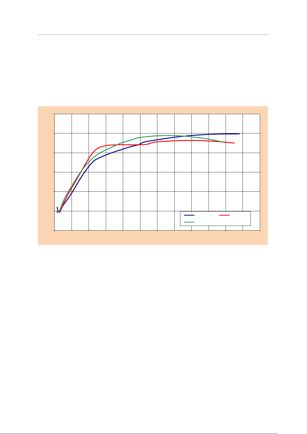
Economical long-life light sources with plug-in bases
0
20
40
60
80
100
120
0 50 100 150 200 250 300
Relative luminous flux [%]
Run-up time [sec]
base down
horizontal
base up
Compact Fluorescent Lamps OSRAM DULUX®
Technical Guide
heats up and releases mercury into the discharge. This behaviour can be especially observed under
lower temperatures.
Therefore in CONSTANT lamps an additional run-up amalgam is positioned in the direct neighbourhood of the electrode. After the lamp is switched on, the electrode will heat up the flag containing
the run-up amalgam, so that mercury is directly released into the discharge. This results in a quick
run-up behaviour of the CONSTANT lamp that is nearly identical to a Cold Spot lamp.
Once all the mercury from the run-up amalgam is released, the operation amalgam will take over the
Hg vapour pressure control, until its final stabilization (until the light output is stabilized).
Typical run-up behaviour of OSRAM DULUX® T/E CONSTANT (amalgam lamps) in ECG operation, 25 ºC
ambient temperature, mains voltage 230 V/ 50 Hz, free-operating
58
Page 61
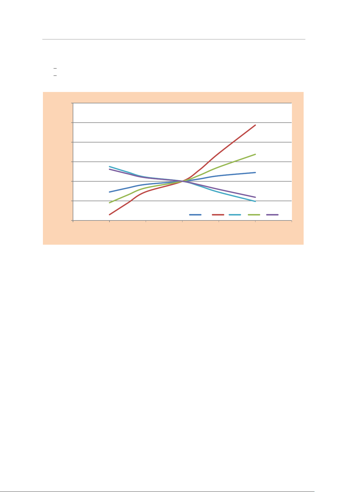
Economical long-life light sources with plug-in bases
80
90
100
110
120
130
140
85 90 95 100 105 110 115
Relative values [%]
Mains voltage [%]
Phi I U P eta
Compact Fluorescent Lamps OSRAM DULUX®
4.4 Operating values of the lamps as a function of mains voltage
Operating position: Base up, free-operating
Ambient temperature: 25 °C
Technical Guide
Typical curves for the electrical an photometric data as a function of mains voltage for OSRAM DULUX® lamps
in reference magnetic ballast operation.
For ECG operation the variation of luminous and electrical parameters with variation of mains
voltage depends strongly on the individual ECG design. There are current controlled, power
controlled and mixed controlled characteristics available, which keep the respective electrical
parameters more or less constant. The photometric parameters of the lamp will follow the
operational parameters of the ECG.
59
Page 62

Economical long-life light sources with plug-in bases
40
50
60
70
80
90
100
110
120
-20 -10 0 10 20 30 40 50 60 70 80
Relative values [%]
Ambient temperature [°C]
Lamp voltage
Lamp current
Lamp power
0
20
40
60
80
100
120
-10 0 10 20 30 40 50 60 70
Relative values [%]
Ambient temperature [°C]
ULp [V]
PLp [W]
ILp [A]
Compact Fluorescent Lamps OSRAM DULUX®
Technical Guide
4.5 Operating values of the lamps as a function of ambient temperature
Operating position: Base up, free-operating
Mains voltage: 230 V
curves for the electrical data as a function of ambient temperature for OSRAM DULUX® lamps in magnetic
operation
Typical curves for the electrical data as a function of ambient temperature for OSRAM DULUX
lamps in ECG operation with constant current
®
60
Page 63

Economical long-life light sources with plug-in bases
40
50
60
70
80
90
100
110
120
-10 0 10 20 30 40 50 60 70 80 90
Relative values [%]
Ambient Temperature [°C]
ULp [V]
PLp [W]
ILp [A]
Compact Fluorescent Lamps OSRAM DULUX®
Technical Guide
Chart for the electrical data as a function of ambient temperature for OSRAM DULUX® L CONSTANT in
constant current operation
61
Page 64

Economical long-life light sources with plug-in bases
Compact Fluorescent Lamps OSRAM DULUX®
Technical Guide
4.6 Luminous flux as a function of temperature and operating position
OSRAM DULUX
®
lamps achieve 100 % luminous flux at ambient temperatures of 15ºC or 25ºC
respectively, depending on the operating position, after a certain run-up time has elapsed, as the
graphs above show (see 4.3).
The OSRAM DULUX® HE range achieves 100% luminous flux at an ambient temperature of about
35°C.
For free-operating lamps, the ambient temperature corresponds to the room temperature. If lamps
are operated in luminaires, the temperature in the immediate vicinity of the lamp is the one that is
relevant to any measurement of luminous flux.
The lamps can be operated in any operating position. However, different burning positions and
different ambient temperatures will lead to different luminous flux values. This is due to temperature
changes at certain locations on the lamp.
OSRAM DULUX®, OSRAM DULUX® HE, SP, XT and ES lamps which use the standard Cold Spot
technology, luminous flux is controlled by the so called Cold Spot. For this reason, we speak of the
cold spot temperature. This temperature affects the mercury vapour pressure in the lamp and
therefore the luminous flux. The luminous flux/temperature graph depends on the operating position
of the lamp. Different operating positions cause the cold spot to be heated in different ways and
reach different temperatures. Knowledge of the luminous flux/temperature graph is important for
light fitting designers. The base-up operating position is preferred for indoor lighting, for example,
whereas the base down operating position for out-door lighting (compare the values at 0 ºC, for
example).
For OSRAM DULUX® CONSTANT technology based lamps, amalgam controls vapour pressure and
luminous flux. Similarly to the cold spot, the amalgam temperature is affected not only by the
ambient temperature, but in certain way by the operating position of the lamp. And so the luminous
flux/temperature graphs for different operating positions are different.
OSRAM DULUX®, HE, OSRAM DULUX
®
CONSTANT lamps are optimised for various temperature
ranges.
OSRAM DULUX
®
CONSTANT lamps are ideal for high ambient temperatures. They produce 90 % of
their maximum luminous flux over a wide temperature range from 5°C to 70°C. Installed in a suitable
light fitting, the lamps are able to achieve high performance even under cold ambient temperatures
too.
If OSRAM DULUX® CONSTANT lamps and OSRAM DULUX
®
Cold Spot lamps are combined in the
same installation there will be visible differences in colour perception and brightness. For this
reason these two types may not be mixed.
Depending on the operating position the maximum luminous flux will be reached only after a certain
Run-up time (see 4.3). Under optimum conditions in magnetic ballast and ECG operation, all the
lamps require an aging period of 100 h.
For DULUX D, DE, T, T/E and CONSTANT multilimbed lamps in horizontal operating position it is
important to know that the location of the electrodes (facing towards to or facing away from the
reflector) has a direct impact on the performance of the lamp. Differences in luminous flux or
brightness will appear. Electrodes facing towards to the reflector will result in a maximum luminous
flux at higher ambient temperature than for the case with the electrodes facing away from the
reflector. On the other hand, with the electrodes facing towards to the reflector the cap temperature
will be significantly increased compared to operation with the electrodes facing away from the
reflector (see 4.8.1).
Note that it is essential for the design of the luminaire to perform the light and temperature
measurement for both kinds of horizontal lamp orientation. Under any conditions the maximum
lamp cap temperature may not be exceeded.
62
Page 65

Economical long-life light sources with plug-in bases
0%
20%
40%
60%
80%
100%
120%
-20 -10 0 10 20 30 40 50 60 70 80
Relativ luminous flux in %
Ambient temperature [°C]
base up and horizontal
base down
0
20
40
60
80
100
120
0 10 20 30 40 50 60 70
Relative luminous flux [%]
Ambient Temperature [°C]
base up, horizontal
Compact Fluorescent Lamps OSRAM DULUX®
Technical Guide
4.6.1 Luminous flux/temperature graphs for OSRAM DULUX
Typical luminous flux/temperature graphs (here OSRAM DULUX® T/E)
®
lamps in general
4.6.2 Luminous flux/temperature graphs for OSRAM DULUX
®
HE base up (horizontal)
The luminous flux for the DULUX T/E HE lamps peaks at 35°C in order to meet the requirements
from application with increased temperature inside luminaires.
63
Page 66

Economical long-life light sources with plug-in bases
30
40
50
60
70
80
90
100
110
-10 -5 0 5 10 15 20 25 30 35 40 45 50 55 60 65 70 75
Relative luminous flux [%]
Ambient temperature [°C]
Horizontal
Base up
10
20
30
40
50
60
70
80
90
100
110
-20 -10 0 10 20 30 40 50 60
Relative luminous flux (%)
Ambient temperature [°C]
horizontal
base up
base down
Compact Fluorescent Lamps OSRAM DULUX®
Technical Guide
4.6.3 Luminous flux/temperature graphs for OSRAM DULUX
4.6.4 Luminous flux/temperature graphs for OSRAM DULUX
®
CONSTANT lamps
®
L SP for outdoor lighting
64
Page 67

Economical long-life light sources with plug-in bases
60
65
70
75
80
85
90
95
100
105
-10 -5 0 5 10 15 20 25 30 35 40 45 50 55 60 65 70 75 80 85 90
Relative luminous flux [%]
Ambient temperature [°C]
base up
horizontal
base down
base down 45°
Compact Fluorescent Lamps OSRAM DULUX®
Technical Guide
4.6.5 Luminous flux/temperature graphs for OSRAM DULUX
®
L Constant
65
Page 68

Economical long-life light sources with plug-in bases
Compact Fluorescent Lamps OSRAM DULUX®
Technical Guide
4.6.6 Operation at high temperatures
On conventional linear fluorescent lamps, the cold spot is normally in the centre of the lamp.
Additionally the luminaire will generally have a large radiating surface which will ensure moderate
tube wall temperatures and high efficiency. In contrast to linear fluorescent lamps, compact
fluorescent lamps are much shorter despite having high lamp wattages. Therefore there is a
tendency to make luminaires as small as possible. Often the thermal characteristics are ignored.
In particularly small enclosed luminaire systems the temperatures at the points on normal OSRAM
DULUX
®
lamps that have a major influence on luminous flux are so high that luminous flux and
therefore the efficiency of the luminaire are reduced appreciably.
Since in such cases the lamps are no longer operated at their optimum, there are also changes in
the electrical values of the lamp (reduced lamp power) at high ambient temperatures, which in turn
will impair the control gear and shorten the life of the lamp. Therefore it is important to take into
account the maximum temperatures permitted on the lamp (see 4.8).
At high ambient temperatures, where OSRAM DULUX® Cold Spot lamps cannot be operated at their
optimum (reduced luminous flux), it is advisable to use OSRAM DULUX
®
CONSTANT lamps to
achieve maximum luminous flux. Since they achieve their optimum mercury vapour pressure over a
wide range of lamp ambient temperature, CONSTANT lamps operate at their optimum efficiency
under the same conditions in narrow luminaires and therefore achieve a higher lamp power.
All the electrical and photometric values (lamp current, lamp voltage and luminous flux) relate to the
higher lamp output. In narrow luminaires equipped with OSRAM DULUX
is therefore more heat released than it is the case with Cold Spot OSRAM DULUX
®
CONSTANT lamps, there
®
lamps. This
leads to an increase in temperature at the IEC measuring point of the lamp and the Tc point of the
electronic control gear and must be taken into consideration when designing the luminaires, or
when replacing a Cold Spot lamp by a CONSTANT lamp in an existing narrow fitting. (see
measuring points , chapter 4.8.
For more information related to the maximum permitted temperature at the IEC measuring point,
see chapter 4.8.
4.6.7 Operation at low temperatures
The following points must be taken into account when operating OSRAM DULUX
magnetic ballasts or ECGs at low temperatures:
1. The lamp must be capable of starting at the required temperature.
2. After ignition, the tube wall must warm up sufficiently for the lamp to operate
within its optimum range
The low ambient temperatures at which OSRAM DULUX
magnetic ballasts are shown in 4.2. If operated with suitable electronic control gear, OSRAM
DULUX
In low-temperature applications, the lamps should be used only in enclosed luminaires. It is
important for the luminaire to be of such volume, that the lamp(s) can warm up rapidly so that
ambient temperatures at which the lamps will operate efficiently are reached within a short time
(especially using CONSTANT lamps, which need a longer time to reach the optimal temperature and
light output – see 4.3). If there are considerable fluctuations in temperature, the luminous
flux/temperature graphs for the different operating positions should be studied in order to achieve a
suitable compromise between lamp and luminaire efficiency.
Operation at low ambient temperatures should be taken into consideration when designing the light
fitting, especially for CONSTANT lamps. This is to improve the run-up behaviour and to enable the
lamps to reach an optimal and stable luminous flux level.
®
lamps with four-pin bases can ignite at even lower temperatures.
®
lamps on
®
will ignite reliably in conjunction with
66
Page 69

Compact Fluorescent Lamps OSRAM DULUX®
4.7 Dimming
Important notes regarding the dimming of single capped CONSTANT and Cold Spot lamps:
For optimum operation, new lamps should be aged for 100 hours at full output before they are
dimmed for the first time.
CONSTANT lamps react more slowly than Cold Spot lamps on variations in supplied electrical
power or ambient temperature. For this reason it is strictly recommended not to mix the two types in
an installation.
After stabilisation, colour temperature differences can be visible between dimmed (3 % luminous
flux) and undimmed lamps (100 % luminous flux).
When the lamps are dimmed to the lowest dimmer setting (3 % luminous flux) the colour
temperature shift compared with undimmed lamps might initially be significant. After a stabilization
period of 30 to 40 minutes (for CONSTANT lamps) or 20 to 30 minutes (for Cold Spot lamps) this
difference is reduced again.
4.7.1 Dimming of OSRAM DULUX CONSTANT lamps
Economical long-life light sources with plug-in bases
Technical Guide
The technical requirements for dimming also apply to CONSTANT lamps without restrictions. Note
also that the chemical activity of the amalgam causes a delayed reaction of the lamp with regard to
changes in power. This generally occurs with visible differences from one lamp to another. When
CONSTANT lamps are dimmed there may therefore be noticeable differences in brightness and
colour perception between lamps of the same type, even if they are operated under identical
conditions.
The luminous flux of free-operating OSRAM DULUX® CONSTANT lamps stabilises at 100 % after 15
to 30 minutes. In the case of OSRAM DULUX
®
Cold Spot lamps the luminous flux stabilizes within
less than 10 minutes.
These differences in brightness between CONSTANT lamps of the same wattage can also occur if
the lamps are operated in luminaires with different volumes. In such cases the different
temperatures within the luminaires have an effect on the light output of the lamps.
CONSTANT lamps can however be dimmed, with the restrictions mentioned above. For detailed
information about CONSTANT lamps in dimming operation in conjunction with OSRAM ECG (BAT1)
please see www.osram.com.
If the lamps are stored or switched off for a long period of time (> 20 hours) the mercury may
migrate into the amalgam. At low dimmer settings and low ambient temperatures, there is then the
possibility that the lamp will produce only very low light output (Hg-free stage, burning pink). This is
caused by a too low discharge temperature and no mercury present in the discharge (described in
4.3).
The solution is to allow the lamp to operate for about 5 minutes at full output and then to dim it (no
damage to the lamp).
For optimum operation, new lamps should be aged for 100 hours at full output before they are
dimmed for the first time.
1
best available technology
67
Page 70

Economical long-life light sources with plug-in bases
Compact Fluorescent Lamps OSRAM DULUX®
Technical Guide
Why is a 100 h ageing period necessary?
To meet the electrical and photometric requirements, all compact fluorescent lamps have to be
aged (operated) for 100 hours according to IEC 60901 (single capped fluorescent lamps). This is
necessary to stabilise lamp operation and get the emitter material on the electrodes into its final
shape.
Compact fluorescent lamps operated with dimmable electronic control gear (BAT) must always be
stabilised at full (100%) light output. Intermittent operation at full light output is acceptable to reach
the 100 hours criteria.
Avoiding operation of the lamps for 100 hours at full light output will result in flickering and
premature blackening which finally yields reduced life of the lamps.
1. Recommendation for new installations:
Usually in the construction phase at the building site, all lamps in the light fittings must be operated
at full light output and NOT in dimmed mode. Under these conditions the electrodes will be
stabilised at the time the lighting installation is provided (hand over).
In particular in light ceilings or Light fittings, in which compact fluorescent lamps are not directly
visible, stabilising the lamp for 100h is an absolute advice.
2. Recommendation for the replacement of lamps in existing lighting installations:
Compact fluorescent lamps have long life span and are manufactured to tight tolerances. Dimming
and non dimmed applications have the same life span (mortality) and same lumen maintenance of
the lamps. We recommend bulk replacement and in dimmed application the replaced lamps must
have been aged for 100 hours at full light output.
In some installations with BMS (Building Master Control System) control, it may be difficult to age
the lamps at 100% light output. In such applications, we recommend that the lamps are aged
separately in another location. This can be realised in an operating position, different from the final
application.
Some advance BMS control have an automatic detection when lamps are replaced that may allow
stabilising of lamps by operating at full light output for 100 hours before dimming is applied.
Conclusion:
It is necessary to stabilise the lamps for 100 hours at full light output. Failure to do this will result in
short lamp life.
Scientific approach
As mentioned above, there is the requirement that compact fluorescent lamps shall be operated for
a minimum of 100h at rated lumen output, i.e. not dimmed, prior to any dimmed lamp operation.
Consumers often ask whether this requirement is really necessary, why it is necessary and what
would happen if there is no 100h burn-in period at rated discharge current.
The answer to this question lies in the chemical structure of the emitter material on the electrode
coils of the low pressure discharge lamps.
All electrode coils of low pressure discharge lamps from any brand are usually coated with a so
called emission mix, which is a mixture of Barium- Strontium- and Calcium-Oxide. This mixture of
oxides reduces the electron work function of the electrode. That means, the energy, which is
required to drag current out of the electrode into the discharge of the lamp is reduced. The
reduction is as high as about a factor of 2 to 3.
68
Page 71

Economical long-life light sources with plug-in bases
Compact Fluorescent Lamps OSRAM DULUX®
Technical Guide
Picture of an electrode for low pressure discharge lamps, consisting of 2 lead wires and a tungsten electrode
coil which is covered by (white) emitter.
The problem with these oxides is that they are highly hygroscopic. This means, if they come into
contact with air, they will suck up a lot of moisture which then is trapped inside of the lamp, leading
to low light output, high lamp voltage and short lamp life. The trick, lamp manufacturers use, is to
put Barium-, Strontium- and Calcium-Carbonate on the electrodes instead of the oxides. The
carbonates are stable when they are in contact with air. During the exhaust process of the lamp,
when the air is pumped out of the lamp and the lamp is then filled with the designed fill gas, the
electrodes which are covered with the carbonates are heated up to a temperature of 600°C and
above. At that high temperature the carbonate changes into oxide by releasing CO2 as shown in the
equation.
After this reaction is finished, another chemical reaction is necessary to reduce the electron work
function of the electrode-emitter system, where atomic Barium is released and transported to the
surface of the emitter. The reaction takes place at the surface of the tungsten wire, which the
electrode is made of below the emitter coating and follows the equation
Once enough atomic Ba has reached the outer surface of the emitter, the electrode is ready f or its
work. This last reaction then continues over the whole life of the lamp and electrode.
When the reaction is started for the first time in a new lamp, it will take a significant amount of time
until the first coverage of Ba on the emitter surface is ready. This process needs a high emitter and
coil temperature, which usually is only given when the lamp operates at the rated discharge current
with a hot spot on the electrode where a temperature of about 1900K is reached. If the lamp is
operated in a dimmed mode, the temperature on the coil is lower and got a wider distribution.
Therefore the described process does not happen as effectively as in the operation at rated current.
The consequence then is that the electrode is not in a proper shape and the electron work function
is higher than with a properly conditioned electrode. This makes an increased temperature on the
electrode necessary which is realized by an increased cathode fall voltage in front of the electrode.
By this cathode fall voltage, ions from the plasma are accelerated to the electrode and yield an extra
69
Page 72

Economical long-life light sources with plug-in bases
Compact Fluorescent Lamps OSRAM DULUX®
Technical Guide
heating but also sputter material from the electrode, which causes destruction and therefore
reduction of electrode and lamp life.
It has to be mentioned that the reaction for the formation of Ba on the emitter surface as shown
above needs to take place right at the beginning of lamp operation, i.e. in the first 100h. Once the
lamp has been operated some time in a dimmed mode without the 100h burn-in period, the reaction
will not happen in a proper way anymore, because the structure of the W – BaO interface on the
surface of the electrode under the emitter coating has changed.
70
Page 73

Compact Fluorescent Lamps OSRAM DULUX®
Measuring point
Description
Max. temp.
0
This point is located at the bottom of the base and is
determined by the thermal load capacity of the glow starter
installed in the bases of two-pin lamps for conventional
operation. It is therefore relevant only for these lamps
(OSRAM DULUX® S, D, T and T IN).
90°C1)
according to EN 60901
1
IEC
Measuring point
(old - for information)
Information for lamp holder manufacturers
Defined as the point lying between the tubes containing
electrodes on a line tangential to the tubes. The limit value for
this measuring point has been defined in the relevant
standard for safety reasons. (If this maximum temperature is
exceeded the plastic base may start to soften (applies to end
of life).
Refer to chapter 4.8.1
Maximum allowed temperature
and measuring conditions
according to IEC 61199.
1*
IEC measuring point
(new)
For luminaire manufacturers
Defined as the point lying between the tubes containing
electrodes on a line tangential to the tubes. The limit value for
this measuring point has been defined in the relevant
standard for safety reasons. (If this maximum temperature is
exceeded the plastic base may start to soften (applies to end
of life).
Refer to chapter 4.8.1
Maximum allowed temperature
and measuring conditions
according to IEC 61199.
3
Cold spot measuring
point
Applies only to OSRAM DULUX® two-pin and OSRAM
DULUX® four-pin Valid for Cold spot lamps. Corresponds to
the cold spot for base-up measuring burning position and a
free-operating lamp. Under certain circumstances, however,
the cold spot may shift to somewhere else on the lamp
surface than measuring point 3.
Exceeding the maximum permitted temperature has a
considerable impact on the electrical and photometric data of
the lamp and will cause the lamp to fail.
For CFL Square lamps the cold spot is located inside the
lamp cap. For measuring purposes specially prepared lamps
are necessary.
In magnetic and ECG operation
max. 100°C (approx. <50%
luminous flux) optimum 40°-50°C
(=100% luminous flux)
3
Temperature limit for
lamp performance of
CONSTANT lamps
For safety reasons a new measuring point located on the
glass bend of the lamp was defined.
Ecxeeding the maximum permitted temperature on
measuring point 3 has a considerable impact on the
electrical and photometric data of the lamp and can lead to
lamp failures or a reduced lamp life time.
OSRAM DULUX® L CONSTANT
40W, 55W, 80W, maximum
125°C
OSRAM DULUX® T/E CONSTANT
26W, 32W, 42W, maximum
150°C
Amalgam measuring
point
CONSTANT lamps : The measuring point for CONSTANT
lamps is located on the glass tip of the amalgam reservoir
inside the lamp base. This temperature can be measured only
with specially prepared lamps.
DULUX T, T/E CONSTANT,
optimum amalgam temperature
100°C – 160°C (= 90% luminous
flux)
Measuring point for
DULUX® L CONSTANT is not
accessible.
CFL SQUARE®
1
4.8 Lamp temperature, safety and limit values
Economical long-life light sources with plug-in bases
Technical Guide
Temperature measuring points are defined for OSRAM DULUX
®
lamps. The temperatures measured
at these points must be within the thresholds for a safe and reliable operation of the lamps.
1) Measuring Conditions:
25°C ambient temperature, draught free air
Reference ballast
Supply voltage UV=1.06 × U
rated
71
Page 74

Economical long-life light sources with plug-in bases
Measuring point
limit values
0
As per EN 60901
3
OSRAM DULUX® 2-pin (CCG operation)
90°C
100°C
OSRAM DULUX® 4-pin (ECG operation)
–
100°C
OSRAM DULUX® CONSTANT 2-pin (CCG operation)
90°C
OSRAM DULUX® CONSTANT 4-pin (ECG operation)
–
–
OSRAM CFL SQUARE® (CCG operation)
-
100°C
OSRAM CFL SQUARE® (ECG operation)
-
100°C
Highest temperature
point on the cap
Distance
Circumferencial line on the
side surface
Compact Fluorescent Lamps OSRAM DULUX®
Technical Guide
4.8.1 Maximum temperatures for OSRAM DULUX
The following table shows the permitted maximum temperatures on OSRAM DULUX® lamps.
Exceeding one or more of the maximum values specified here will lead to:
a noticeable reduction in lamp life
and/or damage to the CCG or ECG
and/or damage to the lamp base and the luminaire holder.
In the case of OSRAM DULUX
measuring point 3 (cold spot) should not be exceeded. Exceeding this limit value may cause the
lamp to fail. At cold spot temperatures above the optimum (see table 4.8) there are changes in the
electrical and photometric data of the lamps (the luminous flux is no longer at 100 %).
In case of CFL SQUARE® lamps, the cold spot is located inside the cap, i.e. special prepared lamps
are needed.
In case of CONSTANT lamps (with amalgam) mercury vapour pressure inside the lamp is controlled
by the amalgam temperature, which needs to be measured inside the lamp cap (special prepared
lamps are needed).
The limit value at measuring point 1 is 140ºC for OSRAM DULUX® lamps with and without amalgam.
This maximum value was defined as part of the IEC standard for safety reasons. Exceeding this
value leads to softening of the plastic base and discolouration of the base material.
®
S, D, T (without amalgam), L and F the limit value of 100 ºC at
®
lamps
For the limit values at measuring point 1, 1* for OSRAM DULUX
®
lamps with and without amalgam
please refer to the measuring descriptions and tables below.
Measurement point 1 maximal lamp cap temperatures – locations and values as per IEC 61199
Measurement point 1, locations on the cap surface
72
Page 75

Economical long-life light sources with plug-in bases
Compact Fluorescent Lamps OSRAM DULUX®
Technical Guide
A. Information for luminaires manufacturers.
Maximum lamp cap temperature (measuring point 1*).
The highest temperatures on the lamp cap occur close to the electrode-containing legs. Those legs
have only one connection (bridge or bend) to another leg.
For lamps having electrodes in adjacent legs (example A)
The temperature shall be measured at the lamp cap surface, on the outer tangent plane connecting
the electrode-containing legs, at the point halfway between the two legs. In case there are 2
symmetric outer tangent planes, any of them can be used. If the shortest distance between its
position and the surface of the electrode-containing leg is more than 3 mm, the measurement
position shall be taken at a position on the tangent at a distance 3 mm from the surface of the
electrode-containing leg. In the latter case one shall take measurements at both electrode containing legs and take the highest temperature reading, to identify the worst case situation in
case of asymmetrical thermal load to the electrodes.
For the CFL SQUARE® lamp (GR8 and GR10q caps all wattages)
The temperature shall be measured at a point on the cap surface which is equidistant between the
two glass limbs emerging from the cap. It shall also lie on the straight line that joins the axes of the
glass limbs.
73
Page 76

Economical long-life light sources with plug-in bases
Lamp Lamp nominal wattage
W°
Maximum cap temperature
°C
DULUX® F
All
200
CFL SQUARE® 2, 4 pin
All
110 *
DULUX® L (XT, CONSTANT)
18, 24, 36
200
DULUX® S
All
200
DULUX® D, D/E (XT), D ES
All
200
DULUX® T, T/E (CONSTANT)
13, 18, 24
200
Lamp Lamp nominal wattage
[W]
Maximum cap temperature
[°C]
DULUX® S/E, DULUX® F, DULUX® L (CONSTANT, HE, SP, XT)
All
180
CFL SQUARE® 4 pin
All
100*
DULUX® D/E, T/E (CONSTANT, HE, XT)
All
180
Compact Fluorescent Lamps OSRAM DULUX®
Technical Guide
Maximum cap temperature, lamps with internal or external starter (test at abnormal operating
conditions)
* Under consideration.
If a magnetic ballast with (short-circuited) internal or external starter is used, the luminaire designer
should ensure that the cap temperature of the lamp, under abnormal operating conditions, does not
exceed the maximum cap temperature value shown in the table above.
Luminaires should be tested using the intended lamp with the starter short-circuited (test at
abnormal operating conditions), i.e. the cathodes operated in series.
Maximum cap temperature, lamps for ECG operation (test at normal operating conditions)
* Under consideration
If a high frequency ballast is used, the luminaire designer should ensure that the cap temperature of
the lamp under normal operating conditions does not exceed the maximum temperature value
shown in the table above.
74
Page 77

Economical long-life light sources with plug-in bases
Lamp
Distance X
mm
DULUX® S, S/E
8
DULUX® D, D/E, T, T/E, L, F
12
Lamp Lamp nominal wattage
W
Maximum cap temperature
°C
DULUX® S/E, DULUX® F, DULUX® L
All
140
CFL SQUARE® 2,4 pin
All
110
DULUX® D, D/E, T, T/E
All
140
Compact Fluorescent Lamps OSRAM DULUX®
Technical Guide
B. Information for lamp holder manufacturers
Maximum lamp cap temperature related to the lamp - lampholder interface. (Measuring point 1-old)
The point where the temperature limit is given is the hottest point on the cap surface at a distance x
from the reference plane of the cap, as indicated in table below, in the direction of the glass limbs
(see: Measurement point 1 location on the cap surface, in chapter 4.8.1 Maximum temperatures for
OSRAM DULUX® lamps, p.72).
Temperature point location:
Temperature point for CFL SQUARE® lamps
The point where the temperature limit is given is a point on the cap surface, which is equidistant
between the two glass limbs emerging from the cap, and which lies on the straight line that joins the
axes of the glass limbs.
Maximum temperatures related to lampholder design
4.8.2 Maximum electrical safety values for OSRAM DULUX
Electrical safety data for electronic operation to be observed (normal operation).
SoS max – maximal Sum Of Squares of the pin currents, defines the maximal permanent heating
energy supplied to one electrode.
Id max – maximal permitted lamp current. Exceeding the maximal lamp current can lead to damage
to lamp, lamp cap or lamp holder.
For lamps in high frequency operation, the pre-heat current must not be applied over a period of
more than 10 sec. If a lamp does not start within this period, the current through the electrodes has
to be reduced until the SoS value for the currents through the lead wires at each electrode stays
below the ”Maximum SoS value” as specified in table below. Also at end of lamp life the ballast has
to prevent overheating by suitable measures.
®
lamps as per IEC 61199
75
Page 78

Economical long-life light sources with plug-in bases
Lamp
Discharge current safety limit
mA
SoS safety limit
A
2
OSRAM DULUX® S/E 7 W
190
0.20
OSRAM DULUX® S/E 9 W
190
0.20
OSRAM DULUX® S/E 11 W
190
0.20
OSRAM DULUX® D/E 10 W
210
0.15
OSRAM DULUX® D/E 13 W
210
0.15
OSRAM DULUX® D/E 18 W
240
0.20
OSRAM DULUX® D/E 26 W
360
0.27
OSRAM DULUX® T/E 13 W
210
0.15
OSRAM DULUX® T/E 18 W
240
0.20
OSRAM DULUX® T/E 26 W1)
360
0.27
OSRAM DULUX® T/E 32 W1)
360
0.27
OSRAM DULUX® T/E 42 W1)
360
0.27
OSRAM DULUX® T/E 11W HE
210
0,06
OSRAM DULUX® T/E 14W HE
210
0,06
OSRAM DULUX® T/E 17W HE
210
0,06
OSRAM DULUX® L 18 W (SP)
690
0.90
OSRAM DULUX® L 24 W (SP)
690
0.90
OSRAM DULUX® L 36 W (SP)
690
0.90
OSRAM DULUX® L 40 W1)
690
0.90
OSRAM DULUX® L 55 W1)
690
0.90
OSRAM DULUX® L 80 W1)
690
0.90
OSRAM DULUX® L 28W HE
250
0,30
OSRAM DULUX® F 18 W
690
0.90
OSRAM DULUX® F 24 W
690
0.90
OSRAM DULUX® F 36 W
690
0.90
CFL SQUARE® 16W
690
0.90
CFL SQUARE® 28W
690
0.90
CFL SQUARE® 38W
690
0.90
Compact Fluorescent Lamps OSRAM DULUX®
Technical Guide
Safety data for electronic operation for DULUX® lamp.
1) also for DULUX® CONSTANT
76
Page 79

Compact Fluorescent Lamps OSRAM DULUX®
5 Data for control gear manufacturers
Economical long-life light sources with plug-in bases
Technical Guide
Compact fluorescent lamps cannot be operated directly from the mains supply; they need a control
gear. This may be integrated in the lamp (as in the case of OSRAM DULUX
the form of an external unit connected between the lamp and the mains outlet (as with all CFLs with
pin bases).
Models with two-pin bases are designed to operate with magnetic control gear; lamps with four-pin
bases are designed to operate with electronic control gear (high frequency operation). In either
case, the operating data of the control gear must be tailored to the lamp data.
5.1 Electronic operation
The advantages of high-frequency operation (BAT) are higher efficiency, longer lamp life, higher
number of switching cycles and more comfortable light than it is the case with choke/starter
circuits. To make best use of these advantages, however, it is important to ensure that the
permissible operating data listed below for preheating, igniting and operating the lamps is followed.
The values in the table apply to an operating frequency of 25 kHz and a sinusoidal voltage during
operation without starting aid.
5.1.1 Preheating (ECG operation)
Starting lamps with filament preheating (warm start) is recommended by OSRAM as the standard
starting procedure. In a warm start, the electrodes are heated by a preheating current with energy
Qpreheat to the emission temperature before the lamp is ignited.
®
EL lamps) or may take
The necessary or permissible preheating current is determined by the design of the electrodes and
the preheating time tpreheat selected. Preheating times of less than 0.4 s are generally not
permissible for compact fluorescent lamps. This is because with such short times it is impossible to
ensure sufficiently uniform heating along the entire length of the electrode. The minimum and
maximum permitted preheating energy can be calculated using the parameters in the following table
for various preheating times. Violating these limit values will cause blackening around the electrodes
and shorter lamp life, particular if the lamp is switched on and off frequently. Compliance with the
prescribed limits is tested on control gear using an equivalent resistor Rsub which is connected to
the control gear instead of the lamp electrodes. The energy fed into this resistor is measured over
the selected preheating time. For the testing of the minimum limit Qpreheat, min a substitution resistor
Rsub min is used. For the maximum limit (correspond with a higher electrode resistance) a
substitution resistor Rsub max is used.
The minimum and maximum value of the preheat energy is calculated by
Qpreheat, min = Q + Pt preheat
Qpreheat, max = 2 x Q preheat, min
If electrode preheating is carried out with a constant current Ipreheat or constant voltage Upreheat the
necessary current or voltage can be calculated as follows:
77
Page 80

Economical long-life light sources with plug-in bases
Lamp
P [W]
Q [J]
Rsub [Ω]
min
max
min
max
min
max
OSRAM DULUX® S/E 7 W
0.5
1.0
1.0
2.0
30
40
OSRAM DULUX® S/E 9 W
0.5
1.0
1.0
2.0
30
40
OSRAM DULUX® S/E 11 W
0.5
1.0
1.0
2.0
30
40
OSRAM DULUX® D/E 10 W
0.6
1.2
1.0
2.0
30
40
OSRAM DULUX® D/E 13 W
0.7
1.4
1.0
2.0
30
40
OSRAM DULUX® D/E 18 W 3)
0.7
1.4
0.9
1.8
18
24
OSRAM DULUX® D/E 26 W 3)
0.8
1.6
1.0
2.0 9 12
OSRAM DULUX® T/E 13 W
0.7
1.4
1.0
2.0
30
40
OSRAM DULUX® T/E 18 W
0.7
1.4
0.9
1.8
18
24
OSRAM DULUX® T/E 26 W
1)
0.8
1.6
1.0
2.0 9 12
OSRAM DULUX® T/E 32 W
1) 3)
0.8
1.6
1.0
2.0 9 12
OSRAM DULUX® T/E 42 W1)
3)
0.8
1.6
1.0
2.0 9 12
OSRAM DULUX® T/E 11W HE
0.7
1.4
1.0
2.0
30
40
OSRAM DULUX® T/E 14W HE
0.7
1.4
1.0
2.0
30
40
OSRAM DULUX® T/E 17W HE
0.7
1.4
1.0
2.0
30
40
OSRAM DULUX® L 18 W 3)
0.9
1.8
1.5
3.0 8 11
OSRAM DULUX® L 24 W 3)
0.9
1.8
1.5
3.0 8 11
OSRAM DULUX® L 36 W 3)
1.0
2.0
1.6
3.2 7 9
OSRAM DULUX® L 40 W1)
0.9
1.8
1.5
3.0 8 11
OSRAM DULUX® L 55 W1) 3)
1.1
2.2
2.4
4.8 5 6.5
OSRAM DULUX® L 80 W1)
1.5
3.0
2.4
4.8 5 6.5
OSRAM DULUX® L 16 W HE
0.75
1.5
0.9
1.8
30
45
OSRAM DULUX® L 22 W HE
0.75
1.5
0.9
1.8
30
45
OSRAM DULUX® L 26 W HE
0.75
1.5
0.9
1.8
30
45
OSRAM DULUX® L 28 W HE
0.75
1.5
0.9
1.8
30
45
OSRAM DULUX® F 18 W
0.9
1.8
1.5
3.0 8 11
OSRAM DULUX® F 24 W
0.9
1.8
1.5
3.0 8 11
OSRAM DULUX® F 36 W
1.0
2.0
1.6
3.2 7 9
CFL SQUARE® 16W2)
0.6
1.2
0.9
1.8
40
50
CFL SQUARE® 28W2)
0.9
1.8
1.1
2.2
12
16
CFL SQUARE® 38W2)
1.0
2.0
2.0
4.0
5.6
8.2
Compact Fluorescent Lamps OSRAM DULUX®
Technical Guide
1) Also for DULUX® CONSTANT
2) CFL SQUARE®® four-pin base
3) also for XT versions
5.1.2 Starting (ECG operation)
The lamp should not ignite during the preheating time; the open-circuit voltage of the ECG must
therefore not exceed a lamp-specific maximum value. After the preheating phase the lamp should
ignite reliably; the open-circuit voltage of the ECG must therefore not fall below a lamp-specific
minimum value. The following table contains the permissible or necessary limit values for the opencircuit voltage of the ECG. Because of the temperature response of the ignition voltage of
fluorescent lamps and compact fluorescent lamps, these values are given for two ambient
temperature ranges.
78
Page 81

Economical long-life light sources with plug-in bases
Lamp
Maximum open-circuit
voltage during preheating
Vrms
Minimum open-circuit
voltage for ignition
Ambient temperature
>+10°C
Vrms
Minimum open-circuit
voltage for ignition
Ambient temperature
-15°C to +10°C
Vrms
OSRAM DULUX® S/E 7 W
130
270
320
OSRAM DULUX® S/E 9 W
150
290
340
OSRAM DULUX® S/E 11 W
170
330
370
OSRAM DULUX® D/E 10 W
180
340
360
OSRAM DULUX® D/E 13 W
190
380
420
OSRAM DULUX® D/E 18 W (XT)
220
400
460
OSRAM DULUX® D/E 26 W (XT)
240
420
520
OSRAM DULUX® T/E 13 W
190
400
430
OSRAM DULUX® T/E 18 W
250
430
450
OSRAM DULUX® T/E 26 W
265
500
520
OSRAM DULUX® T/E 32 W (XT)
265
530
550
OSRAM DULUX® T/E 42 W (XT)
265
550
575
OSRAM DULUX® T/E 11 W HE
265
450
575
OSRAM DULUX® T/E 14 W HE
300
475
625
OSRAM DULUX® T/E 17 W HE
350
600
650
OSRAM DULUX® T/E 18 W
CONSTANT
250
550
550
OSRAM DULUX® T/E 26 W
CONSTANT
265
550
560
OSRAM DULUX® T/E 32 W
CONSTANT
265
560
600
OSRAM DULUX® T/E 42 W
CONSTANT
265
600
600
OSRAM DULUX® L 18 W (XT, SP)
150
300
320
OSRAM DULUX® L 24 W (XT, SP)
170
320
340
OSRAM DULUX® L 36 W (XT, SP)
190
340
380
OSRAM DULUX® L 40 W1)
220
360
420
OSRAM DULUX® L 55 W
1)
(XT)
220
360
420
OSRAM DULUX® L 80 W1)
230
370
420
OSRAM DULUX® L 16 W HE
170
320
375
OSRAM DULUX® L 22 W HE
190
340
410
OSRAM DULUX® L 26 W HE
220
360
450
OSRAM DULUX® L 28 W HE
230
370
420
OSRAM DULUX® F 18 W
130
350
390
OSRAM DULUX® F 24 W
170
400
440
OSRAM DULUX® F 36 W
190
420
480
CFL SQUARE® 16W
265
550
600
CFL SQUARE® 28W
265
550
650
CFL SQUARE® 38W
265
550
560
Compact Fluorescent Lamps OSRAM DULUX®
Technical Guide
1) Also for DULUX® L CONSTANT
79
Page 82

Economical long-life light sources with plug-in bases
Lamp
Minimum lamp current
(undimmed)
mA
Maximum lamp current
1)
mA
Maximum current
in any lead
mA
OSRAM DULUX® S/E 7 W
120
190
240*
OSRAM DULUX® S/E 9 W
120
190
240*
OSRAM DULUX® S/E 11 W
120
190
240*
OSRAM DULUX® D/E 10 W
135
210
240*
OSRAM DULUX® D/E 13 W
120
190
240*
OSRAM DULUX® D/E 18 W (XT)
160
240
330*
OSRAM DULUX® D/E 26 W (XT)
220
360
480
OSRAM DULUX® T/E 13 W
120
190
240*
OSRAM DULUX® T/E 18 W 2)
160
240
330*
OSRAM DULUX® T/E 26 W 2)
220
360
480
OSRAM DULUX® T/E 32 W 2) (XT)
220
360
480
OSRAM DULUX® T/E 42 W 2) (XT)
220
360
480
OSRAM DULUX® T/E 11W HE
100
170
170
OSRAM DULUX® T/E 14W HE
100
170
170
OSRAM DULUX® T/E 17W HE
100
170
170
OSRAM DULUX® L 18 W (XT, SP)
260
425
640
OSRAM DULUX® L 24 W (XT, SP)
260
425
640
OSRAM DULUX® L 36 W (XT, SP)
300
500
700
OSRAM DULUX® L 40 W 2)
260
425
640
OSRAM DULUX® L 55 W
2)
(XT)
450
650
780
OSRAM DULUX® L 80 W 2)
425
690
740
OSRAM DULUX® L 16 W HE
130
205
220
OSRAM DULUX® L 22 W HE
130
205
220
OSRAM DULUX® L 26 W HE
130
205
220
OSRAM DULUX® L 28 W HE
130
205
220
OSRAM DULUX® F 18 W
260
425
640
OSRAM DULUX® F 24 W
260
425
640
OSRAM DULUX® F 36 W
300
500
700
CFL SQUARE® 16W
110
195
220
CFL SQUARE® 28W
215
350
380
CFL SQUARE® 38W
340
550
590
Compact Fluorescent Lamps OSRAM DULUX®
Technical Guide
5.1.3 Operating data for undimmed lamps
All the lamp data is specified only for operation at rated current. The lamp current may vary within
the tolerance range without affecting lamp life. Detailed data are shown in the table below. In this
range there is no need for constant heating current to maintain the electrodes at emission
temperature. The critical load of a lamp is determined by two criteria: (1) the maximum lamp current
and (2) the maximum current maximum in any lead. The lamp current is the current that goes
through the discharge in the lamp. The current maximum in any lead is a limit value for the load
capacity of the power supply leads if a heating current flows in addition to the lamp current. The
current in any lead equals approximately the lamp current plus the heating current.
This table complies with the latest edition of IEC 60901 and 61199.
*IEC 61199 is currently being revised. As a result, these values may change.
1) Exceeding the maximum lamp current may shorten lamp life (overheating of the base) and a decrease in maintenance
2) Also for DULUX® CONSTANT
80
Page 83

5.1.4 Dimming
2222
,
HeatdHeatdcurrentHeatingcurrentLampHeat
IIfIIfPPP
2
2
2
1 PinPinHeat
IIfP
Reducing the lamp current below the minimum value specified in 5.1.3 can be used to reduce the
luminous flux of the lamp appreciably below its rated value, thereby dimming the lamp. The
dimming range is defined as the lamp current region between the “minimum lamp current
(undimmed)” and the “minimum lamp current” in the table below. Please note the following:
The lamp electrodes must be maintained at emission temperature by a continuous heating
current.
The lamp voltage at lower discharge current is generally higher than the rated value.
The chromaticity coordinate of the light colour may deviate from its rated value.
In the interest of maximising lamp life, the auxiliary heating current must be matched to the lamp
current. If the auxiliary heating current is too low, the lamp electrodes will very quickly be destroyed
by sputtering. A constant heating current that is too high will result in excessive emitter evaporation
which leads to end blackening.
Economical long-life light sources with plug-in bases
Compact Fluorescent Lamps OSRAM DULUX®
Technical Guide
Generally speaking, it is not easy to measure the continuous heating current when the lamp is being
operated on an electronic control gear (BAT) because of two reasons. First, the current is fed to the
electrodes in the lamp via the two lead wires in a split that depends on the design of the control
gear. Second, the lamp current and the auxiliary heating current may differ in phase, wave shape
and frequency. Therefore it is not reasonable to specify the necessary auxiliary heating current as a
function of the lamp current.
The important variable for electrode heating is the electrical heating power Pheat fed to the electrode.
As:
or
81
Page 84

Economical long-life light sources with plug-in bases
2
2
2
1 PinPin
II
1Pin
I
2Pin
I
1Pin
I
2Pin
I
Compact Fluorescent Lamps OSRAM DULUX®
Technical Guide
The necessary auxiliary heating current can also be specified as a function of lamp current by
indicating the total of:
which is called the “Sum of the Squares” of the pin current (SoS)
and
are the two pin currents at an electrode in the lamp.
and
can be easily
measured on electronic control gear.
As the diagram above shows, there is an ideal target setting for the sum of the squares of the two
pin currents at which the lamp life will be at its optimum. If the sum of the squares of the pin
currents decreases, sputtering will occur at the electrodes. As a result, lamp life will be drastically
reduced.
If the sum of the squares of the pin currents increases with respect to the target value, end
blackening gradually occurs and at very high values for heating the life of the lamp is gradually
reduced due to high thermal evaporation of the emitter material.
82
Page 85

The data are shown in the table below:
Lamp
Minimum
lamp current
[A]
mTarget
[A2/A]
bTarget
[A2]
mmin
[A2/A]
Y1 [A]
bmin
[A2]
X1 [A2]
mmax
[A2/A]
Y2 [A]
bmax
[A2]
X2 [A2]
I LLmax
[A]
I LHmax
[A]
OSRAM DULUX® S/E 7 W
0.015
0.072
0.030
0.240
0.030
0.061
0.040
0,137
0,182
OSRAM DULUX® S/E 9 W
0.015
0.072
0.030
0.240
0.030
0.061
0.040
0,137
0,182
OSRAM DULUX® S/E 11 W
0.015
0.072
0.030
0.240
0.030
0.061
0.040
0,137
0,182
OSRAM DULUX® D/E 10 W
0.015
0.078
0.035
0.260
0.035
0.066
0.045
0,147
0,196
OSRAM DULUX® D/E 13 W
0.015
0.078
0.035
0.260
0.035
0.066
0.045
0,147
0,196
OSRAM DULUX® D/E 18 W (XT)
0.020
0.105
0.065
0.350
0.065
0.089
0.080
0,200
0,266
OSRAM DULUX® D/E 26 W (XT)
0.030
0.171
0.175
0.570
0.175
0.146
0.210
0,326
0,434
OSRAM DULUX® T/E 13 W
0.015
0.078
0.035
0.260
0.035
0.066
0.045
0,147
0,196
OSRAM DULUX® T/E 18 W1)
0.020
0.105
0.065
0.350
0.065
0.089
0.080
0,200
0,266
OSRAM DULUX® T/E 26 W1)
0.030
0.171
0.175
0.570
0.175
0.146
0.210
0,326
0,434
OSRAM DULUX® T/E 32 W1) (XT)
0.030
0.171
0.175
0.570
0.175
0.146
0.210
0,326
0,434
OSRAM DULUX® T/E 42 W1) (XT)
0.030
0.171
0.175
0.570
0.175
0.146
0.210
0,326
0,434
OSRAM DULUX® T/E 11W HE
0.015
0.0693
0.028
0.231
0,028
0,059
0,032
0,130
0,170
OSRAM DULUX® T/E 14W HE
0.015
0,0693
0,028
0,231
0,028
0,059
0,032
0,130
0,170
OSRAM DULUX® T/E 17W HE
0.015
0,0693
0,028
0,231
0,028
0,059
0,032
0,130
0,170
OSRAM DULUX® L 18 W (XT, SP)
0.035
0.189
0.210
0.630
0.210
0.160
0.254
0,357
0,476
OSRAM DULUX® L 24 W (XT, SP)
0.035
0.189
0.210
0.630
0.210
0.160
0.254
0,357
0,476
OSRAM DULUX® L 36 W (XT, SP)
0.040
0.213
0.270
0.710
0.270
0.181
0.326
0,404
0,539
OSRAM DULUX® L 40 W1)
0.035
0.189
0.210
0.630
0.210
0.160
0.254
0,357
0,476
OSRAM DULUX® L 55 W1) (XT)
0.050
0.279
0.450
0.930
0.450
0.235
0.550
0,525
0,700
OSRAM DULUX® L 80 W1)
0.055
0.306
0.550
1.020
0.550
0.259
0.666
0,578
0,770
OSRAM DULUX® L 16 W HE
0.020
0,090
0,050
0,300
0,050
0,075
0,055
0,170
0,220
OSRAM DULUX® L 22 W HE
0.020
0,090
0,050
0,300
0,050
0,075
0,055
0,170
0,220
OSRAM DULUX® L 26 W HE
0.020
0,090
0,050
0,300
0,050
0,075
0,055
0,170
0,220
OSRAM DULUX® L 28 W HE
0.020
0,090
0,050
0,300
0,050
0,075
0,055
0,170
0,220
OSRAM DULUX® F 18 W
0.035
0.189
0.210
0.630
0.210
0.160
0.254
0,357
0,476
OSRAM DULUX® F 24 W
0.035
0.189
0.210
0.630
0.210
0.160
0.254
0,357
0,476
OSRAM DULUX® F 36 W
0.040
0.213
0.270
0.710
0.270
0.181
0.326
0,404
0,539
CFL SQUARE® 16W
0.015
0.072
0.030
0.240
0.030
0.037
0.061
0,136
0.182
CFL SQUARE® 28W
0.027
0.150
0.130
0.500
0.130
0.16
0.130
0.280
0.380
CFL SQUARE® 38W
0.040
0.234
0.320
0.780
0.320
0.390
0.195
0.440
0.590
Economical long-life light sources with plug-in bases
Compact Fluorescent Lamps OSRAM DULUX®
Technical Guide
2
I
2
I
2
I
Pin 1
Pin 1
Pin 1
+ I
+ I
+ I
2
2
2
Pin 2 Target
Pin 2 min
Pin 2 max
= – m
= – m
= + m
Target
* Id + b
min
* Id + b
max
* Id + b
Target
= SoS
min
max
= SoS
= SoS
min
max
Target
1) Also for DULUX CONSTANT
83
Page 86

Economical long-life light sources with plug-in bases
Compact Fluorescent Lamps OSRAM DULUX®
Technical Guide
The diagram shows an example of an OSRAM DULUX
®
D/E 26 W lamp.
The Id „1-pin“ and Id „2-pin“ lines in the diagram show the discharge current for the two limiting cases.
1. The discharge current of the lamp is fed only via one lead wire
2. The discharge current of the lamp is fed equally via the two lead wires
The intersection of the curve with the line Id „1-pin“ with I
2
Pin 1
+ I
2
min (= minimum) gives the value
Pin 2
of the minimum discharge current below which heating must be provided.
The optimum dimming operation would be along the target line. If there are any deviations toward
smaller values for I
2
Pin 1
+ I
2
the life of the lamp will be significantly reduced. If I
Pin 2
2
Pin 1
+ I
2
is above
Pin 2
the target value, blackening might be observed at the ends of the lamp. Proper lamp operation
cannot take place below the „Minimum“ line or above the „Maximum“ line. Only burning duration
tests can give a reliable indication of achievable lamp life in dimmer mode. These tests must be
performed by the control gear manufacturers. Control gear manufacturers are also responsible for
carrying out tests on the permissible ambient temperature ranges and on stability in dimmer mode.
For optimum operation, new lamps should be burnt in (seasoned) for 100 hours at full output before
they are dimmed for the first time.
84
Page 87

Economical long-life light sources with plug-in bases
Preheating
Ignition
Lamp
Impedance
1)
Rated
preheating
current
mA
Preheating
current
mA
Substitute resistance
2)
Open circuit voltage
DULUX®
At
220
V
At
230
V
At
240
V
Rated value
at
220/230/240
min
mA
max
mA
At
220
V
At
230
V
At
240
V
220
V
min
Vrms
230
V
min
Vrms
240
V
min
Vrms
max
VPeak
DS 5 W
1180
1240
1300
190
190
153
240
160
160
160
198
207
216
400
DS 7 W
1180
1240
1300
190
190
153
240
160
160
160
198
207
216
400
DS 9 W
1180
1240
1300
190
190
153
240
160
160
160
198
207
216
400
DS 11 W
1180
1240
1300
190
190
153
240
160
160
160
198
207
216
400
2 x DS 5 W
1070
1140
1210
190
190
153
240
320
320
320
198
207
216
400
2 x DS 7 W
1070
1140
1210
190
190
153
240
320
320
320
198
207
216
400
2 x DS 9 W
1070
1140
1210
190
190
153
240
320
320
320
198
207
216
400
DD 10 W
1070
1140
1210
210
210
153
275
100
100
100
198
207
216
440
DD 13 W
1070
1140
1210
210
210
153
275
100
100
100
198
207
216
440
DD 18 W
800
845
900
280
280
190
375
80
80
80
198
207
216
440
DD 26 W
540
571
610
420
420
270
550
25
25
25
198
207
216
440
DD ES 16W
800
845
900
280
280
190
375
80
80
80
198
207
216
440
DD ES 23W
540
571
610
420
420
270
550
25
25
25
198
207
216
440
DT 13 W3)
1070
1140
1210
210
210
153
275
100
100
100
198
207
216
440
DT 18 W3)
800
845
900
280
280
190
375
80
80
80
198
207
216
440
DT 26 W
3) 4)
540
571
610
420
420
270
550
25
25
25
198
207
216
440
DL 18 W
540
568
600
510
510
315
670
50
50
50
198
207
216
400
DL 24 W
540
568
600
510
510
315
670
50
50
50
198
207
216
400
DL 36 W
390
419
447
650
650
365
775
40
40
40
198
207
216
400
2 x DL 18 W (XT)
390
419
447
540
510
315
670
80
100
100
198
207
216
400
DF 18 W
540
568
600
510
510
315
670
50
50
50
198
207
216
400
DF 24 W
540
568
600
510
510
315
670
50
50
50
198
207
216
400
DF 36 W
390
419
447
650
650
365
775
40
40
40
198
207
216
400
2 x DF 18 W
390
419
447
540
510
315
670
80
100
100
198
207
216
400
Compact Fluorescent Lamps OSRAM DULUX®
5.2 Magnetic operation
5.2.1 Magnetic operation 220 V/230V and 240V, 50Hz/60Hz
The following table shows the data for magnetic control gear for OSRAM DULUX® lamps.
Technical Guide
1) For the calibration current of the reference control gear (see 2.2.2 and 2.2.3) Tolerance ± 3%.
2) Substitution resistance of both electrodes connected in series.
3) Control gear for OSRAM DULUX® D 13, 18 and 26 W can also be used to operate OSRAM DULUX® T 13, 18 and 26 W.
4) Also for CONSTANT model
85
Page 88

Economical long-life light sources with plug-in bases
Lamp
Test current
IT
mA
Warm resistance
RT at IT
Cold resistance
R0 measured at the
pins
OSRAM DULUX® S/E 7 W
130
50±12.5
11.1
OSRAM DULUX® S/E 9 W
130
50±12.5
11.1
OSRAM DULUX® S/E 11 W
130
50±12.5
11.1
OSRAM DULUX® D/E 10 W
140
50±12.5
11.1
OSRAM DULUX® D/E 13 W
140
50±12.5
11.1
OSRAM DULUX® D/E 18 W (XT)
190
26±6.5
6.2
OSRAM DULUX® D/E 26 W (XT)
310
13±3.25
3.3
OSRAM DULUX® T/E 13 W
140
50±12.5
11.1
OSRAM DULUX® T/E 18 W
190
26±6.5
6.2
OSRAM DULUX® T/E 26 W
1)
310
13±3.25
3.3
OSRAM DULUX® T/E 32 W
1)
(XT)
310
13±3.25
3.3
OSRAM DULUX® T/E 42 W
1)
(XT)
310
13±3.25
3.3
OSRAM DULUX® T/E 14W HE
120
50±12.5
11.1
OSRAM DULUX® T/E 14W HE
120
50±12.5
11.1
OSRAM DULUX® T/E 17W HE
120
50±12.5
11.1
OSRAM DULUX® L 18 W (XT, SP)
340
12±3.0
3.1
OSRAM DULUX® L 24 W (XT, SP)
340
12±3.0
3.1
OSRAM DULUX® L 36 W (XT, SP)
385
11±2.75
2.9
OSRAM DULUX® L 40 W1)
340
12±3.0
3.1
OSRAM DULUX® L 55 W1) (XT)
500
8±2.0
2.3
OSRAM DULUX® L 80 W
1)
530
8±2.0
2.1
OSRAM DULUX® L 16 W HE
160
40 ± 10.0
8,4
OSRAM DULUX® L 22 W HE
160
40 ± 10.0
8,4
OSRAM DULUX® L 26 W HE
160
40 ± 10.0
8,4
OSRAM DULUX® L 28 W HE
160
40 ± 10.0
8,4
OSRAM DULUX® F 18 W
340
12±3.0
3.1
OSRAM DULUX® F 24 W
340
12±3.0
3.1
OSRAM DULUX® F 36 W
385
11±2.75
2.9
CFL SQUARE® 16W
130
64±16.0
13,5
CFL SQUARE® 28W
270
17.5±4.4
3,7
CFL SQUARE® 38W
420
9±2.25
1,9
Compact Fluorescent Lamps OSRAM DULUX®
Technical Guide
5.3 Electrical data for the filaments
The electrode or filament is an extremely important component of a fluorescent lamp.
To operate the lamp at its optimum it is essential for the filament to be maintained within a particular
temperature range. To ensure that this is the case even if control gear is operated with lamps from
different manufacturers, the filament data are standardised.
The filament of a compact fluorescent lamp is defined such that the warm resistance RT specified in
the following table is in equilibrium when the specified test current flows through the filament. The
cold resistance is not standardised and is shown here for the purposes of completeness only.
1) Also for DULUX CONSTANT
2) Guide value
86
Page 89

Economical long-life light sources with plug-in bases
Lamp
Cap Starter
Coding
OSRAM DULUX® S 5, 7, 9, 11 W
G23
2-pin
integrated
none
OSRAM DULUX® S/E 7, 9, 11 W
2G7
4-pin
none
none
OSRAM DULUX® D 10, 13 W
G24d-1
2-pin
integrated
1 bar central
OSRAM DULUX® D 18 W, D ES 16W
G24d-2
2-pin
integrated
1 bar left
OSRAM DULUX® D 26 W, D ES 23W
G24d-3
2-pin
integrated
1 bar right
OSRAM DULUX® D/E 10, 13 W
G24q-1
4-pin
none
1 bar central, short guidepost1)
OSRAM DULUX® D/E 18 W (XT)
G24q-2
4-pin
none
1 bar left, short guidepost1)
OSRAM DULUX® D/E 26 W (XT)
G24q-3
4-pin
none
1 bar right, short guidepost1)
OSRAM DULUX® T 13 W
GX24d-1
2-pin
integrated
1 bar central, compatible with G24d-1
OSRAM DULUX® T 18 W
GX24d-2
2-pin
integrated
1 bar left, compatible with G24d-2
OSRAM DULUX® T 26 W
2)
GX24d-3
2-pin
integrated
1 bar right, compatible with G24d-3
OSRAM DULUX® T/E 13 W
2)
GX24q-1
4-pin
none
1 bar central, short guidepost1),
compatible with G24q-1
OSRAM DULUX® T/E 18 W
2)
GX24q-2
4-pin
none
1 bar left, short guidepost1), compatible
with G24q-2
OSRAM DULUX® T/E 26 W, 32 W2) (XT)
GX24q-3
4-pin
none
1 bar right, short guidepost
1)
compatible
with G24q-3
OSRAM DULUX® T/E 42 W2) (XT)
GX24q-4
4-pin
none
2 bars central, short guidepost1)
OSRAM DULUX® T/E 11, 14, 17W HE
GR14q-1
4-pin
none
OSRAM DULUX® L 183), 24 3), 363), 402),
552), 80
2)
W (XT)
2G11
4-pin
none
Coding is as per IEC 60901in connection
with a lamp holder at the prescribed
distance from the reference level (see 6.2)
OSRAM DULUX® L 16, 22, 26, 28W HE
2GX11
4-pin
none
OSRAM DULUX® F 18, 24, 36 W
2G10
4-pin
none
None
OSRAM CFL SQUARE® 16, 28W
GR8
2-pin
Integrated
None
OSRAM CFL SQUARE® 16, 28, 38W
GR10q
4-pin
none
None
Compact Fluorescent Lamps OSRAM DULUX®
6 Accessories
6.1 Caps and lampholders
OSRAM DULUX® lamps from the various ranges and compatible lamps from other manufacturers
have different caps, some of which are also coded differently. This prevents the wrong type of lamp
from being used. Using the wrong lamp in a light fitting impairs the safety of the system, often
constitutes a fire risk and leads in most cases to premature lamp failure. It is also important,
however, to follow the instructions of the luminaire manufacturer in selecting the right lamp. This
applies in particular to cases where the same cap/lampholder system is used for two or more lamps
(e.g. GX24q-3 for OSRAM DULUX
and 2G10 for OSRAM DULUX
DULUX
®
S/E 5 W to 11 W, there is no need to code the G23 or 2G7 caps owing to the minimal
differences between the wattages.
Lampholders have a dual role in that they supply power to the lamp and hold the lamp in position.
They must also be able to withstand high temperatures. The quality of the lampholder is therefore
an important aspect. Another factor to bear in mind is that the lampholder must be strong enough to
withstand the stresses involved in removing old lamps and inserting new lamps several times during
the lifetime of the light fitting. The various OSRAM DULUX
for diagrams see 2.1 Geometric data (p. 24).
®
T/E 26 W and 32 W, 2G11 for OSRAM DULUX® L 18 W to 80 W
®
F 18 W to 36 W). In the case of OSRAM DULUX® S and OSRAM
®
caps and their coding are listed below
Technical Guide
1) Lamps will still fit in old „deep“ holders.
2) Also for CONSTANT
3) Also for SP model
OSRAM DULUX
®
bases and their coding pictograms are listed in the chapter 2.1 Geometric data (p.24).
87
Page 90

Economical long-life light sources with plug-in bases
Lamp
Minimum
mm
Maximum
mm
OSRAM DULUX
®
L 18 W (XT, SP)
140
175
OSRAM DULUX
®
L 24 W (XT, SP) and L HE 16 W
140
270
OSRAM DULUX
®
L 36 W (XT, SP) and L HE 22 W
330
365
OSRAM DULUX
®
L 40 W
1)
, 55 W1) (XT) and L HE 26 W
450
485
OSRAM DULUX
®
L 80 W
1)
and L HE 28 W
480
515
Compact Fluorescent Lamps OSRAM DULUX®
Technical Guide
6.2 Lamp supports
OSRAM DULUX
®
L lamps require a lamp support. The distance between the lamp support and the
reference plane of the lamp is defined in the IEC 60901 standard and is given in the table below.
Distance from reference plane e
1) Also for CONSTANT models
Lamp supports are optional for other OSRAM DULUX
OSRAM DULUX
®
F.
®
lamps, such as
Information for light fitting manufacturers:
The use of metallic lamp supports is not recommended. A use of such may lead to deviated lamp
properties under both, normal and dimming operation.
88
Page 91

6.3 Starters
Lamp type
Pulse voltage
V
Non-reclosure voltage
V
RIS capacitor
nF
Minimum
Minimum
Maximum
16W
500*
130
1.0
3.0
28W, 38W
500*
130
5.0
8.0
Economical long-life light sources with plug-in bases
Compact Fluorescent Lamps OSRAM DULUX®
Technical Guide
In magnetic operation, OSRAM DULUX
require a starter for ignition. There is a choice of conventional glow starters or such that are known
as safety starters, e.g. the OSRAM DEOS
®
L (18W, 24W and 36W only) and OSRAM DULUX® F lamps
®
starters. Conventional glow starters should be replaced
whenever lamps are replaced to ensure trouble-free ignition. This is not necessary with safety
starters since they last four times longer than conventional starters. In addition, safety starters
reliably shut down burnt-out or defective lamps in inductive or capacitive operation, which not only
saves the magnetic ballast but prevents annoying flicker from these lamps as they reach the end of
their life.
OSRAM DULUX
starter integrated in the base which ensures reliable ignition. Therefore they do not require external
starters. OSRAM DULUX
®
S, D, T and CFL SQUARE (with two-pin bases) have a specially adapted glow
®
S/E, D/E and T/E (with four-pin bases) are designed for ECG operation
and do therefore not have an integrated glow starter.
OSRAM DULUX
®
S/E, D/E and T/E (13, 18 and 26 W only) can be operated under normal conditions
with magnetic control gear and an external starter. However, there are no special optimised starters
available on the market for this application. See also 3.2.3. In this mode, considerable limitations
can therefore be expected, such as greatly reduced lamp life with electrode blackening and longer
ignition times. For this reason, this mode of operation is not recommended or supported by
OSRAM.
For the operation of the OSRAM CFL SQUARE 4-pin with magnetic control gear and external starter
the OSRAM ST 111 Longlife starter is suitable. For starters from different manufacturers the
following parameters have to be respected.
In general an external starter has to be replaced together with a failed 4-pin lamp. Exceptions are all
DEOS starter types.
Information for starter design for the OSRAM CFL SQUARE® 4-pin
89
Page 92

Economical long-life light sources with plug-in bases
Conditioning (can be part of aging)
[h]
24
Off time (transport to test location)
[min]
5
> 5
Stabilisation time
[min]
15
60
Compact Fluorescent Lamps OSRAM DULUX®
Technical Guide
7 Measuring OSRAM DULUX
OSRAM DULUX
®
lamps differ, in some cases quite considerably, from double capped fluorescent
®
compact fluorescent lamps
lamps in terms of their technical characteristics. In measurements, therefore, particular attention
should be paid to the following (see also IEC 60901):
1. Defined ageing (seasoning) of the lamp (100 hours)
2. Adequate burn-in time (stabilization) before measurements are taken (24 hours, and see
measurement steps under 7.1, p. 90)
3. Constant Ta (ambient temperature) during the measurements (25 ± 1°C)
4. No destabilization due to mechanical vibrations, even when switched off
5. High crest factor resolution for measurement equipment (true rms instruments).
6. Short mains supply and measurement instrument wiring to the lamp (for ECG operation)
If these conditions are met, OSRAM DULUX
®
lamps display good reproducibility of electrical and
photometric values. Reference lamps measured under the following conditions can be obtained
from OSRAM (see 7.6, p. 93).
7.1 Ageing of lamps
Before photometric data is gathered, new lamps should be aged (seasoned) for 100 hours.
During shipping and normal handling of the lamps, e.g. rotating of the lamp, any excess amount of
mercury may be distributed in small droplets within the discharge tube. Proper conditioning is
reached when all the excess mercury has been collected at the coldest spot in the tube. Experience
has shown that initially this process of lamp conditioning may take up to 24 h. When a lamp, once
having passed this conditioning period it is ready for measurement
For conditioning and warming up the lamp may be operated in a location, distant to the test
location. When moving to the test location, provided that the lamp has been kept in the same
position and not subjected to vibration or shock and no warm glass parts are touched (i.e. creating
a parasitic cold spot). Before moving an amalgam lamp to the test location let the lamp cool down
for 1 min in the burning position. A stabilisation period of 15 – 60 minutes (see table) is necessary in
the test location. To avoid cooling down of warm glass parts during moving the lamp to test location
thermally insulating gloves or similar technique shall be used. The interruption of the supply should
be as short as possible.
Measurement of light output and lamp operating voltage must be taken at least once per minute.
During the final 5 minutes of stabilisation time, the difference of maximum and minimum readings of
light output and lamp operating voltage shall be less than 1% of the average of the readings. If this
is not feasible, the real fluctuation shall be stated.
Stabilisation time versus off time
90
Page 93

Economical long-life light sources with plug-in bases
Recommendations
Instruments:
Rms instruments (true RMS)
Accuracy:
±0.2% of the measuring range
Area of application
Frequency:
0-500 Hz (CCG) scanning rate
0-400 kHz (ECG) scanning rate
Crest factor:
> 2 (CCG)
> 3 (ECG)
Lamp supply:
Supply voltage:
Depending on the lamp and control gear (magnetic, electronic or
reference device)
Stability:
± 0.2% during the measurement
Total harmonic distortion:
< 3%
Suitable supply:
– Noise-free mains
– Electronically Regulated stabilisers
– Rotary measuring generators
– Electronic generators
The apparent power of supply unit should be five times the rated system power.
Compact Fluorescent Lamps OSRAM DULUX®
7.2 Operating position
Free-operating OSRAM DULUX® S, S/E, D (ES), D/E (XT), T (XT, CONSTANT), T/E (XT, HE,
CONSTANT) lamps are measured in the base-up position, OSRAM DULUX® L (SP, XT, HE,
CONSTANT), F and CFL SQUARE® are measured in horizontal operating position. All measurements
are according to IEC.
7.3 Constant photometric values
Technical Guide
Aged and stabilised OSRAM DULUX
®
lamps provide reproducible photometric data at constant
ambient temperature and in an unchanged operating position. Fluctuations are less than 1 % of the
upper range value.
7.4 Electrical measurements
All the cables, control gear and instruments must be arranged, and if necessary shielded, so that
there is no chance of interference from external fields. Use instruments which will supply the level of
accuracy required in the measured values.
91
Page 94

Economical long-life light sources with plug-in bases
Compact Fluorescent Lamps OSRAM DULUX®
Technical Guide
7.5 Temperature measurements
The luminous flux and hence the luminous efficacy of OSRAM DULUX
temperature. To achieve optimum operating conditions for the lamp in the luminaire, it is therefore
essential to know either the ambient temperature in the vicinity of the lamp or the cold spot
temperature directly on the lamp.
7.5.1 Ambient temperature
Unless otherwise indicated, the lamp data in this guide is based on an ambient temperature of 25ºC
± 1ºC in draught free air in accordance with IEC 60901. Lamp data as a function of actual ambient
temperature or cold spot temperature is also measured in draught free air.
7.5.2 Cold spot temperature for lamps without amalgam
The cold spot temperatures are dependent on the operating position and lie approximately in the
range from 40ºC to 50ºC (optimum operating conditions). In the base-up operating position and no
air circulation, temperature measuring point 3 (see 4.8, p. 71 – Lamp temperatures and limit values)
generally corresponds to the cold spot. The cold spot can however shift as a result of a different
operating position or other influences.
Measuring point 3 (cold spot temperature in base-up operating position) is
defined for OSRAM DULUX
– except CFL SQUARE® (see 4.8, p. 71). To determine the temperature at
measuring point 3 (not in the case of the CONSTANT version and CFL
SQUARE®) thermocouples (NiCr-Ni thermo-elements) are fixed with a neutral,
translucent adhesive.
®
lamps at the outer lamp arc, centred on the bulb
®
lamps depend on the
To avoid an accidental release of the thermocouple, it is highly recommended
to secure it with a small transparent cable tie (temperature resistance of the
material > 120°C) throughout the whole measurement. Refer to the picture below.
7.5.3 Measuring CONSTANT lamps
CONSTANT lamps are designed for a wide temperature range. They therefore achieve their
optimum operating conditions (>90% of rated luminous flux) in the temperature range from 5°C to
70°C. If photometric measurements are taken under reference conditions (an ambient temperature
of 25ºC, see 7.5.1), it must be remembered that the measured luminous flux may be up to 10%
below the maximum luminous flux that the lamp can produce. Please refer to the luminous flux/
ambient temperature relation graphs (4.6) for detailed information.
In case of horizontal operation of quad and multilimbed lamps it has to be noted that the luminous
flux as a function of ambient temperature also depends on the location of the electrodes (above or
below the symmetry plane of the lamp).
92
Page 95

Economical long-life light sources with plug-in bases
Compact Fluorescent Lamps OSRAM DULUX®
7.6 Reference lamps
Reference lamps (luminous flux and electrical values) can be obtained from the accredited test
laboratory of OSRAM GmbH (DAR register number: DAT-P-043/94-00, Lighting Technology).
DULUX® T/E CONSTANT and CFL SQUARE® lamps for measurements are also available with
thermocouples fixed at the measuring point.
For prices and delivery times please contact:
OSRAM GmbH
Dept./BU: PL PLM TLS PS&S EU&LA&ME
Hellabrunner Str. 1
81536 Munich
Tel.: (+49) 89 6213-2604
Fax.: (+49) 89 6213-4052
Technical Guide
93
Page 96

Economical long-life light sources with plug-in bases
Compact Fluorescent Lamps OSRAM DULUX®
Technical Guide
8 OSRAM DULUX
®
and the environment
8.1 Contents
Like all discharge lamps, OSRAM DULUX
Therefore they do not have any effect on the environment apart from emitting light. The most
important substance in discharge lamps as far as the environment is concerned is mercury.
Discharge lamps must contain some mercury in order to generate light. By using a patented dosing
procedure, OSRAM has succeeded in reducing the amount of mercury in most models to the
currently minimum needed to guarantee reliable operation of around 1.3 mg per lamp.
®
lamps are sealed systems, if used as prescribed.
8.2 Waste disposal
WEEE (Waste Electrical and Electronic Equipment) regulations state that in the
EU since July 1, 2005 all old electrical equipment including failed discharge
lamps must be sent for proper recycling. For private consumers this means that
they will have to hand the old lamps in to local recycling centres free of charge.
In the B2B sector (Business to Business), discharge lamps with mercury residue
qualify as waste requiring special supervision (special waste code) with a
corresponding duty to dispose them carefully. This applies for example to
mercury vapour lamps and (compact) fluorescent lamps.
In Germany this is, today, regulated by the “Kreislaufwirtschaftsgesetz“ and its legislation.
All the above-mentioned lamps affected by the WEEE regulations have a symbol on the packaging
showing a dustbin with a line through it.
94
Page 97

Economical long-life light sources with plug-in bases
Compact Fluorescent Lamps OSRAM DULUX®
8.3 ROHS Directive and conformity for compact fluorescent lamps
Technical Guide
95
Page 98

Economical long-life light sources with plug-in bases
German
European
International
Single-capped
fluorescent lamps
Performance –
specifications
DIN EN 60901
(VDE 0715 Partl 7)
EN 60901
IEC 60901
Single-capped
fluorescent lamps
Safety specifications
DIN EN 61199
(VDE 0715 Part 9)
EN 61199
IEC 61199
Lamp caps and holders
together with gauges for
the control of
interchangeability and
safety
DIN EN 60061
EN 60061
IEC 60061
Part 1: Lamp caps
DIN EN 60061-1
EN 60061-1
IEC 60061-1
Accessories relevant standards
German
European
International
Lamp caps and holders together with
gauges for the control of interchangeability
and safety
DIN EN 60061-1
EN 60061-1
IEC 60061-1
Part 2: Lampholders
DIN EN 60061-2
EN 60061-2
IEC 60061-2
Part 3: Gauges
DIN EN 60061-3
Band I und II
EN 60061-3
IEC 60061-3
Part 4: Guidelines and general information
DIN EN 60061-4
EN 60061-4
IEC 60061-4
Glow starters for fluorescent lamps
DIN VDE 0712
Part 101
EN 60 155
IEC 60155
Ballasts for tubular fluorescent lamps
General and safety requirements
DIN EN 60 920
(VDE 0712 Part 10)
EN 60 920
IEC 60920
Ballasts for tubular fluorescent lamps
Performance requirements
DIN EN 60 921
(VDE 0712 Part 11)
EN 60 921
IEC 60921
DC-supplied electronic control gear for
tubular fluorescent lamps General and
safety requirements
DIN EN 60 924
(VDE 0712 Part 20)
EN 60 924
IEC 60924
AC-supplied electronic ballasts for tubular
fluorescent lamps General and safety
requirements
DIN EN 60 928
(VDE 0712 Part 22)
EN 60 928
IEC 60928
AC-supplied electronic ballasts for tubular
fluorescent lamps Performance
requirements
DIN EN 60 929
(VDE 0712 Part 23)
EN 60 929
IEC 60929
Compact Fluorescent Lamps OSRAM DULUX®
Technical Guide
9 European and international standards
9.1 Relevant standards
9.1.1 Lamps and caps
OSRAM DULUX
following table (see also 9.2 Declaration of Conformity).
9.1.2 Accessories
The following table shows the most important standards that apply to accessories.
®
lamps comply with all relevant European and international standards listed in the
96
Page 99

Accessories relevant standards
German
European
International
Electromagnetic compatibility (EMC)
Section 2: Limits for harmonic currents
emissions (Equipment input current 16A
per phase)
DIN EN 61000-3-2
(VDE 0838 Part 2)
EN 61000-3-2
IEC 1000-3-2
Capacitors for use in tubular fluorescent and
other discharge lamp circuits General and
safety requirements
DIN EN 61 048
(VDE 0560 Part 61)
EN 61 048
IEC 61048
Capacitors for use in tubular fluorescent and
other discharge lamp circuits
Performance requirements
DIN EN 61049
(VDE 0560 Part 62)
EN 61 049
IEC 61049
9.1.3 Luminaires
Luminaires relevant standards
German
European
International
Suppression of radio disturbances
caused by electrical appliances and
systems; limits and methods of
measurement of radio disturbance
characteristics of electrical lighting
and similar equipment
DIN EN 55015
VDE 0875 Part 15
EN 55015
CISPR 15
Equipment for general lighting
purposes, EMC immunity
requirements
DIN EN 61547
EN 61547
IEC 61547
Luminaires
DIN EN 60598
EN 60598
IEC 60598
Part 1: General
requirements and tests
DIN EN 60598-1
(VDE 0711 Part 1)
EN 60 598-1
IEC 60598-1
Fixed general purpose luminaires
purpose luminaires
DIN VDE 0711
Part 201
EN 60 598-2-1
IEC 60598-2-1
Recessed luminaires
DIN VDE 0711 Part 202
EN 60 598-2-2
IEC 60598-2-2
Luminaires for road
and street lighting
DIN EN 60 598-2-3
(VDE 0711 Part 203)
EN 60 598-2-3
IEC 60598-2-3
Portable general purpose
luminaires
DIN EN 60 598-2-4
(VDE 0711 Part 204)
EN 60 598-2-4
IEC 60598-2-4
Floodlights
DIN VDE 0711 Part 205
EN 60 598-2-5
IEC 60598-2-5
Luminaires with built-in
transformers for filament lamps
DIN EN 60598-2-6
(VDE 0711 Part 206)
EN 60 598-2-6
IEC 60598-2-6
Portable luminaires for garden use
DIN EN 60598-2-7
(VDE 0711 Part 207)
EN 60 598-2-7
IEC 60598-2-7
Handlamps
DIN VDE 0711 Part 208
EN 60 598-2-8
IEC 60598-2-8
Photo and film luminaires
(non-professional)
DIN EN 60 598-2-9
(VDE 0711 Part 9)
EN 60 598-2-9
IEC 60598-2-9
Portable child-appealing
luminaires
DIN EN 60598-2-10
(VDE 0711 Part 210)
EN 60 598-2-10
IEC 60598-2-10
Luminaires for stage lighting,
television and film studios
(outdoor and indoor)
DIN VDE 0711 Part 217
EN 60 598-2-17
IEC 60598-2-17
Luminaires for swimming pools and
similar applications
DIN EN 60 598-2-18
VDE 0711 Part 218
EN 60 598-2-18
IEC 60598-2-18
Air-handling luminaires (safety
requirements)
DIN EN 60 598-2-19
VDE 0711 Part 2-19
EN 60 598-2-19
IEC 60598-2-19
Lighting chains
DIN EN 60 598-2-20
VDE 0711 Part 2-20
EN 60 598-2-20
IEC 60598-2-20
The following table shows the most important standards that apply to luminaires.
Economical long-life light sources with plug-in bases
Compact Fluorescent Lamps OSRAM DULUX®
Technical Guide
97
Page 100

Economical long-life light sources with plug-in bases
Luminaires relevant standards
German
European
International
Luminaires for emergency lighting
DIN EN 60 598-2-22
VDE 0711 Part 2-22
EN 60 598-2-22
IEC 60598-2-22
Luminaires for use in clinical
areas of hospitals and health care
buildings
DIN EN 60598-2-25
VDE 0711 Part 225
EN 60 598-2-25
IEC 60598-2-25
Electrical supply track systems
for luminaires
DIN EN 60570
VDE 0711 Part 300
EN 60 570
IEC 60570
Dental equipment
Dental operating light
E DIN EN
pr EN ISO
ISO 9680
ISO 9680
9680
Specifications for lighting fittings with
service voltages below 1000 V
DIN VDE 0710
not yet
available
not yet
available
General requirements
DIN VDE 0710 Part 11)
not yet
available
not yet
available
Special provisions for lamps operated
under adverse conditions
DIN VDE 0710 Part 41)
not yet
available
not yet
available
Specification rules for flush-fitting
signal-light fittings
DIN VDE 0710 Part 111)
not yet
available
not yet
available
Luminaires for aquariums
DIN VDE 0710 Part 121)
not yet
available
not yet
available
To ball throwing luminaires safety
DIN VDE 0710 Part 131)
not yet
available
not yet
available
Luminaires for building-in furniture
DIN VDE 0710 Part 141)
not yet
available
not yet
available
German
European
International
International Lamp Coding
System (ILCOS)
See also 10.
DIN 49805
–
IEC TS 61231
Compact Fluorescent Lamps OSRAM DULUX®
Technical Guide
1) Existing German standard for which there is currently no international counterpart.
9.1.4 Miscellaneous
98
 Loading...