

Data Sheet
DRAGONpuck®
DP3
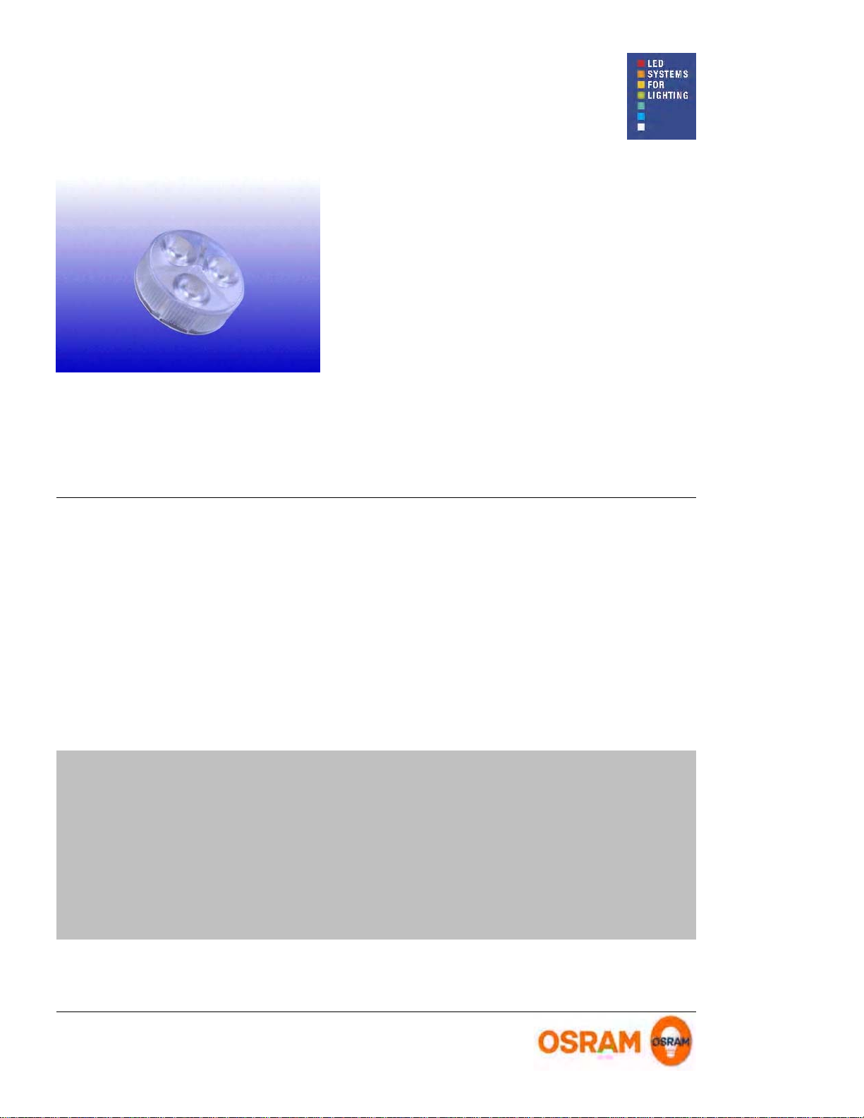
Picture for
Datasheet
Benefits
¾
Compact High-Flux LED light source with
high light intensity
¾
Flat design for wide range of novel
applications
is missing
!!!
Applications
¾
Specialized spot lighting
¾
Reading lights
¾
Small signals
Technical Operating Data
Product Number of
+) Preliminary Data
All Data are related to the entire module
*)
Due to the special conditions of the manufacturing processes of LED the typical data of technical parameters can only reflect statistical figures and do not necessarily
correspond to the actual parameters of each single product which could differ from the typical data.
Color Power
LEDs
white 3,6 20 6500 K 410350DP3-W2B-865 3
white 3,6 16 5400 K 900350DP3-W3F-854 3
white 3,6 20 4700 K 410350DP3-W2B-847 3
white 3,6 16 2700 K 630350DP3-W3F-727 3
red 2,4 20 616 nm 500350DP3-A2 3
red 2,4 16 616 nm 215350DP3-A1 3
yellow 2,4 16 589 nm 215350DP3-Y1 3
green 3,6 16 531 nm 850350DP3-T2 3
verde 3,6 16 505 nm 295350DP3-V1 3
blue 3,6 20 468 nm 115350DP3-B2 3
blue 3,6 16 468 nm 95350DP3-B1 3
Current
[mA]*
[W]*
Radiance
Angle [°]*
Wavelength [nm]
Color Temp [K]*
Lum. Intensity
Technical Features
[cd]*
Operation only with OPTOTRONIC® constant
¾
current devices (see page 3)
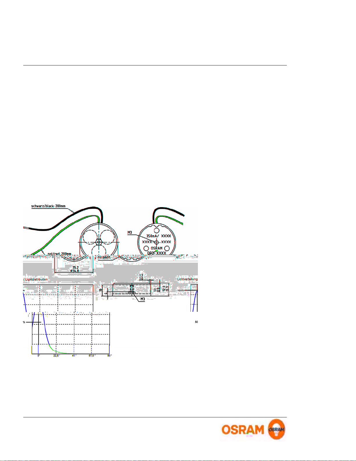
Dimensions: H: 12 mm, Ø : 35 mm
¾
Assembly with M3 scr ew on m etal l i c heat si nk
¾
Factory installed 200 mm / AWG22 double pole
¾
cable
DP3 - 21.09.2007
Page 1 of 4
Protection class IP 22 accord ing t o DIN EN
¾
60529
Proofed according to IEC 60068-2 (shoc k and
¾
vibration)
To obtain maximum LED lifeti me please read
¾
the recommended procedures concerning
thermal management before beginning design
and construction of l uminaires.
Minimum and Maximum Ratings
Product Reverse Voltage
DP3-W2B-865 24-30 85 -30 85... ... 0,5
DP3-W3F-854 24-30 85 -30 85... ... 0,5
DP3-W2B-847 24-30 85 -30 85... ... 0,5
DP3-W3F-727 24-30 85 -30 85... ... 0,5
DP3-A2 24-30 85 -30 85... ... 0,5
DP3-A1 24-30 85 -30 85... ... 0,5
DP3-Y1 24-30 85 -30 85... ... 0,5
DP3-T2 24-30 85 -30 85... ... 0,5
DP3-V1 24-30 85 -30 85... ... 0,5
DP3-B2 24-30 85 -30 85... ... 0,5
DP3-B1 24-30 85 -30 85... ... 0,5
The module is designed to work with current sources. The maximum output voltage may not exceed 100 V DC. Reverse operation is not allowed and may
destroy the module.
Exceeding maximum ratings for operating and storage temperature will reduce expected life time or destroy the LED Module.
*)
Exceeding maximum ratings for operating current will cause hazardous overload and will likely destroy the LED Module. Several modules may be connected in series up to the
maximum voltage of 100 V DC (outside SELV limits).
The temperature of the LED mod u le must be meas ured at th e Tc-point according to EN60598-1 in a thermally constant status with a temperature sensor or a temperature
sensitive label. For exact location of the Tc-point see drawing below.
Operating Temperature
at Tc-Point [ °C ] *
Storage Temperature
[ °C ] *
Max. Current
[ A dc ] *
[ V dc ] *
Drawing
Drawing is missing !!!
DP3 - 21.09.2007
Page 2 of 4

Safety Information
¾
The LED modu le itself and al l its components must not b e mechani cally stressed.
¾
Assembly mu st not dama ge or destroy con ducti ng paths on the circuit board.
The LED Module incorporates no protection against short circuits, overload or overheating. Therefore it is absolutely necessary to
operate the modules with a electronically stabilised power supply offering protection against the above mentioned safety risks.
For dimming applicatio n s a ttention should be paid to specific references in "OPTOTRONIC ® Technical Guide".
OSRAM OPTOTRONIC ® power supplies are specific ally de si gned with pr otecti on features for safe operati on.
When using power supplies other than OPTOTRONIC ® the following basic safety features are required, in addition to any other
application specific concerns and local safety codes:
¾
Short circuit protection
¾
Overload protection
¾
Overheat protection
¾
Installation of LED modules (with power supplies) needs to be made with regard to all applicable electrical and safety standards.
Only qualified personnel should be allowed to perform installations.
¾
Correct e l ectrical polarity nee ds to be observed. Wrong polarity may d estroy the module.
¾
Serial connection is highly recommended as safe electrical operation mode.
Parallel connection is not recommended. Unbala n ce d voltage drop can cause hazardous overload and da mage the LED module.
¾
Recommended powe r supply:
¾
OT 9/200-240/350 or OT 9/100-120/350(E): 350 mA constant current operation
¾
OT 9/10-24/350 DIM, OT 9/10-24/350 DIM(E): 350 mA constant current PWM dimming, 1..10V interface
¾
OT 9/200-240/350 DIM: 0-350 mA constant current ope ra tion, 1..10 V interface (dimming), strain relief
¾
Maxim um number of DP3 for OT9: White/Blue/Green: 2; Red/Y ellow: 3
¾
OT 18/200-240/700 DIM: 0-500 mA constant current opera tion, 1..10 V in terface (dim ming), strain relief.
The OT18 come s with preset li mitation to 500mA, thus giving 12W due to SELV (<=2 5 V )
¾
Maximum number o f LEDs for OT18: White/Blue/Green: 2; Red/Yellow : 3
¾
Pay attention to standard ESD precautions when installing the module.
¾
The module, as manufactured, has no conformal coating and therefore offers no inherent protection against corrosion.
¾
Damage by corrosion will not be honored as a materials defect claim. It is the user's responsibility to provide suitable protection
against corrosive agents such as moisture and condensation and other harmful elements.
DP3 - 21.09.2007
Page 3 of 4

Assembly Information
The mounting of the module is facilitated by means of a M3 screw which fits to a threaded hole in the rear of the DRAGONpuck®
¾
housing. Do not ex ce ed a torque o f 40 Ncm.
The modu le should be in good thermal conta ct w ith the designed metallic moun ti ng surface . Use of an app ropriate hea t sink
¾
compound is recommended to eliminate air gaps.
To obtain maximum LED-lifetime please read carefully the recommended procedures concerning thermal management in our
¾
application note "Lifetime of LED-modules" before beginning construction of luminaires. This application note is available from your
OSRAM representative.
Ordering Guide
Productgroup Productname EAN *
DRAGONpuck® DP3-W2B-865 4008321033406 16
DRAGONpuck® DP3-W3F-854 4008321214508
DRAGONpuck® DP3-W2B-847 4008321033369 16
DRAGONpuck® DP3-W3F-727 4008321214447
DRAGONpuck® DP3-A2 4008321149534 16
DRAGONpuck® DP3-A1 4008321033185 16
DRAGONpuck® DP3-Y1 4008321033420 16
DRAGONpuck® DP3-T2 4008321149510 16
DRAGONpuck® DP3-V1 4008321033345 16
DRAGONpuck® DP3-B2 4008321149473 16
DRAGONpuck® DP3-B1 4008321033208 16
EAN: Ordering number per single module
*)
S-Unit: Modules per shipping unit
Note: Typical performance data are subject to change without any further noti ce, particularly as LED technology ev olve s.
S-Unit *
Sales and Technical Support
OSRAM GmbH
Hellabrunner Strasse 1
D - 81536 München
Germany
www.osram.com
+49 (0)89 6213-0
Sales and tech ni c al support is given by the
local OSRAM subsidiaries.
On our world wide homepage all OSRAM
subsidiaries are listed with complete
address and phone numbers.
Related and Further Information
¾
The new dimension of light
¾
OPTOTRO N IC® D ata Sh eets
¾
OPTOTRONIC® Techn i cal Guid e
¾
OSRAM LE D systems
¾
Application Note: Life Ex pectancy
DP3 - 21.09.2007
153 S006 GB
http://catalog.myosram .com
130 T008 GB
www.osram.com/led-systems
www.osram.com/led-systems-downloads
Page 4 of 4
 Loading...