

Page 1
DIM MCU
Manual control unit
Fitting instructions
Description
A
Purpose and application
The DIM MCU electronic potentiometer (manual control unit)
controls up to 50 dimmable electronic control gears and enables
the manual brightness control of luminaires.
The potentiometer is mounted in ush device boxes.
Function
The potentiometer converts rotations of and pressure on the
rotary knob into 1...10V voltage signals, which are transmitted
to the dimmable electronic control gears.
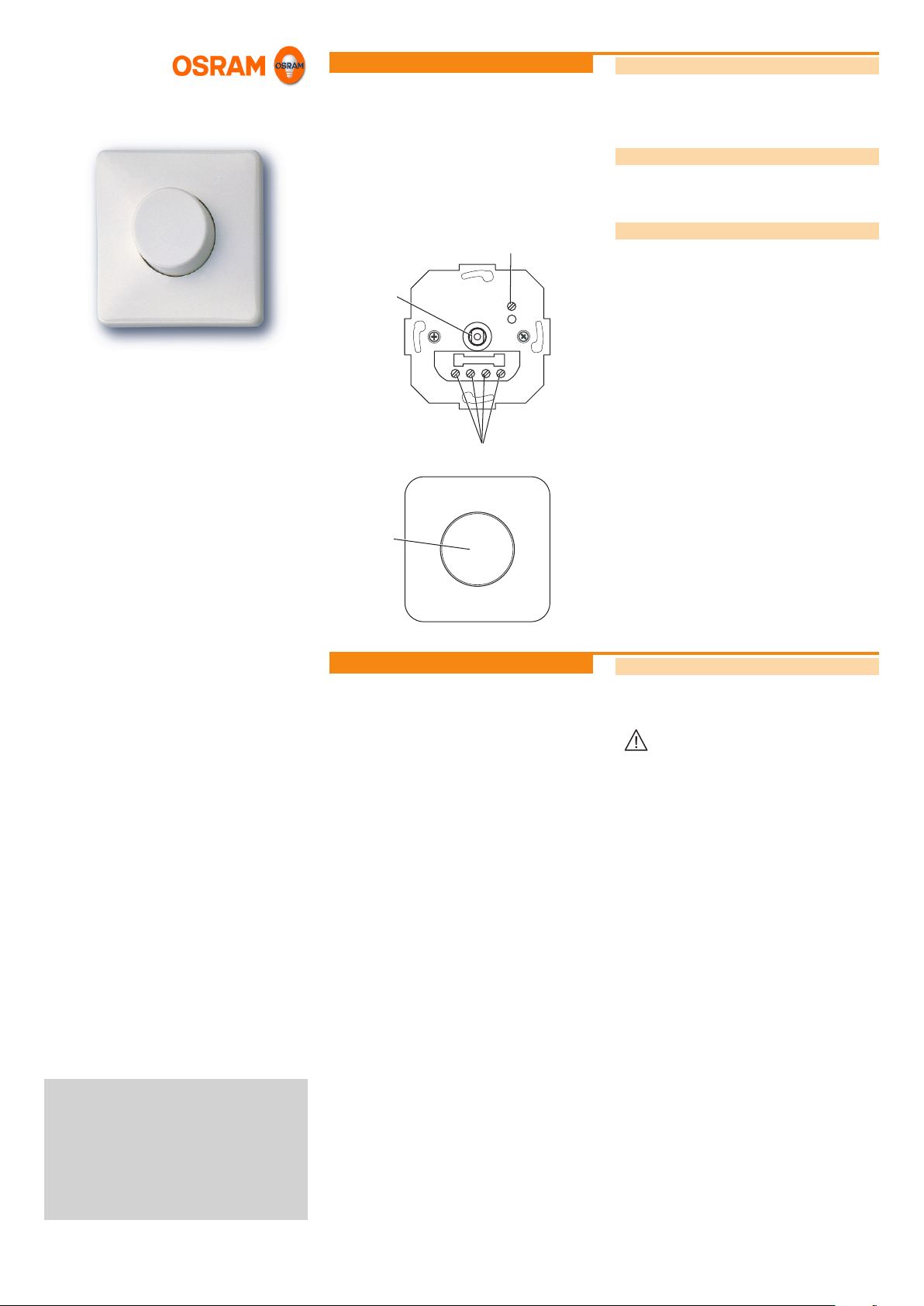
Design
B
↓
–
+
L
C
The potentiometer is made up of the following components:
• Rotary potentiometer (A)
• Connections (C)
– Control lines (+, –)
– Dimmed + switched phase (↓)
– Phase (L)
– Trimmer (B)
• Housing with rotary knob (D)
D
Installation
Safety instructions
The potentiometer must only be installed and put into operation
by a qualied electrician. The applicable safety regulations and
accident prevention regulations must be observed.
WARNING!
Exposed, live cables.
Danger of electric shock!
• Only work on the potentiometer when it is de-
energised.
CAUTION!
Destruction of the potentiometer and other devices
through incorrect mounting!
• The potentiometer is designed for mounting in
ush device boxes. If mounted elsewhere, provideadequate cable strain relief and insulation.
• Do not wire the control line with an external voltage, especially not a mains voltage of 230 V.
• Do not exceed the maximum number of ECGs.
IV 2009
DIM_MCU_ma0904en_we1.01.indd
OSRAM GmbH
Kunden Service Center
Customer-Service-Center (CSC)
Steinerne Furt 62
86167 Augsburg
Germany
Tel : +49 (0) 1803 677 - 200
(kostenpichtig / charges apply)
Fax.: +49 (0) 1803 677 - 202
www.osram.com
www.osram.de
40503003474246
4050300347424
Continued on the back page!
Page 2
Installation (cont.)
71
71
54
51
33
4
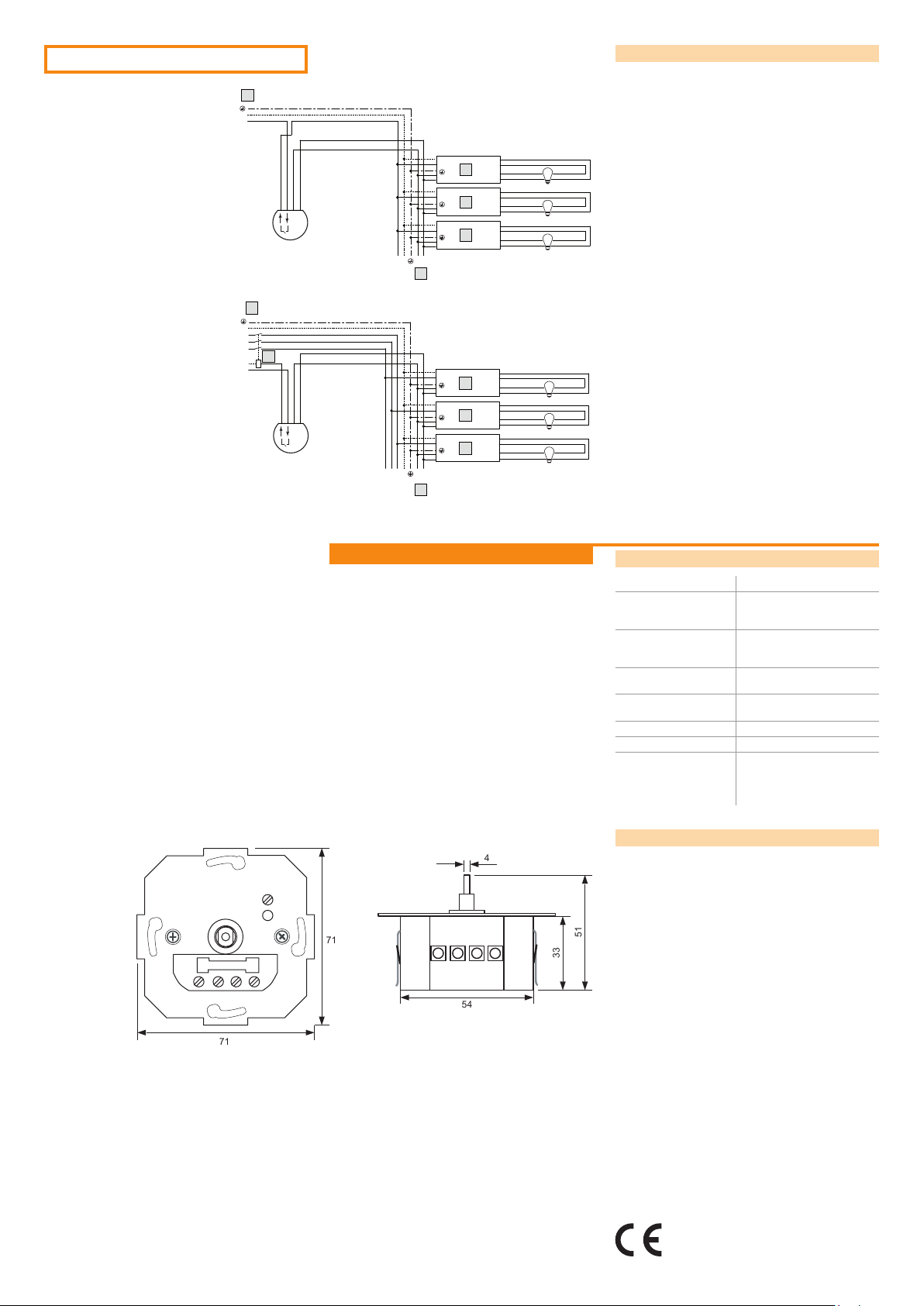
Connecting the potentiometer
E Connection diagram for up to 10 single-lamp or 5 two-lamp
E
N
L
ECGs
F Connection diagram for up to 50 dimmable ECGs
G Dimmable ECG
H Connect max. 10 single-lamp or 5 two-lamp ECGs
I Connect max. 50 dimmable ECGs
K Relay or contactor
_
+
DIM MCU
N
L
_
+
N
L
_
+
N
L
_
+
_
NL
+
1
2
G
3
4
1
2
G
3
4
1
2
G
3
4
H
F
N
3
L
2
L
L
1
K
N
L
_
+
DIM MCU
L1L2L
N
L
_
+
N
L
_
+
N
L
_
+
_
N
3
+
}
1
2
G
3
4
1
2
G
3
4
1
2
G
3
4
I
Appendix
Technical data
Operating voltage 230 V AC, 50-60 Hz
Switching output load
capacity
Control output load
capacity
Permissible line cross
section
Permissible ambient
temperature
Max. 6 A resistive load
(10 single-lamp ECGs or
5 two-lamp ECGs)
Max. 40 mA (max. 50 OSRAM
1...10V ECGs or 16 DIM SA
signal ampliers)
Max. 1.5 mm²
0 °C ... 50 °C
Protection type IP 20
Protection class II
Dimensions Flush-mounted part (Ø x H):
54 x 33 mm
Mounting plate (L x W):
71 x 71 mm
Dimensions
Conformity with the relevant EU directives is
conrmed by the CE symbol.
 Loading...