

Page 1
ZNN 2832397 000 00 Seite 1 von 2 page 1 of 2
DALI HIGHBAY Adapter
DALI HIGHBAY Adapter
EAN 4008321 774132
Bedien- und Montageanleitung
Operating and Mounting Instructions
Stand: Juli 2012
Issued: July 2012
Bild 1 / figure 1
Bild 2 / figure 2
D
Produkt- und Funktionsbeschreibung
Der DALI HIGHBAY ADAPTER ist ein DALI Eingabegerät für
Deckenaufbau und Montage auf Leuchtenmodule. Der Adapter
ist zur Verbindung eines Licht- und Bewegungssensors mit einem übergeordneten DALI – Controller (z.B. OSRAM DALI
PRO CONT-4) gedacht. Das Gerät stellt 2 DALI - Eingangsadressen für Licht und Bewegung zur Verfügung. Die Funktionen
für Licht und Bewegung können getrennt verwendet werden.
Alternativ kann auch der eingebaute Lichtsensor verwendet
werden ohne den Bewegungsmelder zu installieren, dann muß
allerdings der beigefügte Blinddeckel angebracht werden.
Das Gerät versorgt sich über die angeschlossene DALI – Leitung.Die Messwerte der beiden Sensorkanäle sendet der Sensorkoppler als Telegramme über die DALI – Leitung zum zentralen DALI – Controller.
Verdrahtungsprüfung:
Bei angeschlossener DALI –Spannung und einem kurzen Tastendruck auf die SELECT – Taste (Betätigung nur mit Schutzisoliertem Werkzeug!) leuchtet die LED. Ein weiterer kurzer
Tastendruck schaltet die LED wieder aus. Ansonsten geht die
LED nach 30s wieder aus.
Auslieferzustand herstellen:
Bei angeschlossener DALI –Spannung und einem langen Tastendruck >10s auf die SELECT – Taste (Betätigung nur mit
schutzisoliertem Werkzeug!) blinkt die LED für 4s und der Sensorkoppler wird in den Auslieferzustand zurückgesetzt.
Inbetriebnahme:
Die SELECT – Taste (Betätigung nur mit schutzisoliertem
Werkzeug!) kann zur Identifikation des DALI Sensorkopplers
dienen. Vorraussetzung ist, dass der zentrale DALI Controller
in diesen Inbetriebnahmemodus geschalten ist.
Die LED kann für die Inbetriebnahme mit einem zentralen DALI
- Controller beeinflusst werden. Welches Signal (Blinken,
Dauerlicht,…) die LED zeigt ist abhängig vom DALI – Controller
(siehe Bedienungsanleitung DALI – Controller)
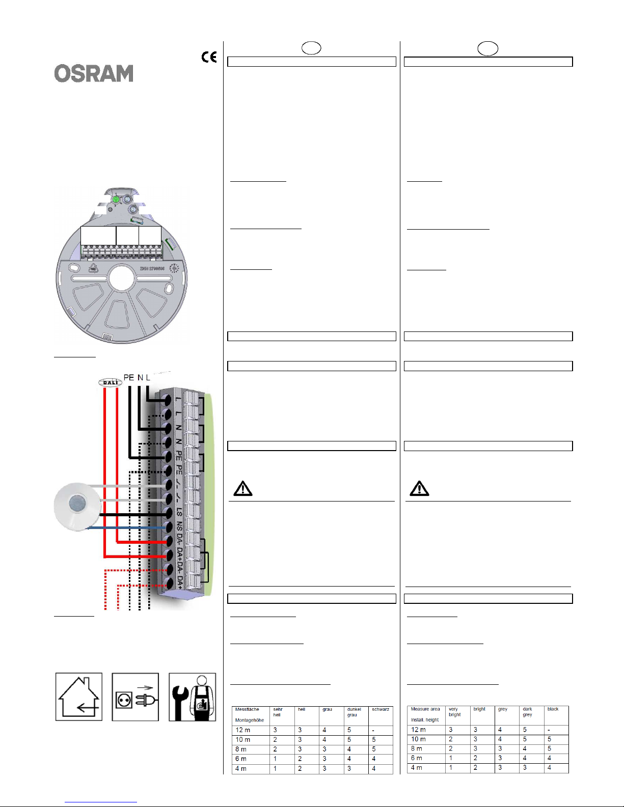
Anschlussbeispiel
siehe Bild 2
Lage und Funktion der Anzeige- und Bedienelemente
siehe Bild 1
A1 Netzanschluss L ,N ,PE + Durchverdrahtung
A2 Sensoranschlüsse
A3 DALI - Anschlüsse + Durchverdrahtung
A4 Einstellung Empfindlichkeit Lichtsensor
A5 SELECT - Taste
A6 Lichtsensor
A7 Anzeige LED
Installationshinweise
Das Gerät kann für feste Installation in trockenen Innenräumen,
zum Deckenaufbau und Montage auf Leuchtenmodule verwendet werden.
WARNUNG
• Das Gerät darf nur von einer zugelassenen Elektrofachkraft
installiert und in Betrieb genommen werden.
• DALI Leitung nicht an 230 V anschliessen.
• Bedienung der SELECT – Taste und des Potentiometers
nur mit schutzisoliertem Werkzeug.
• Die geltenden Sicherheits- und Unfallverhütungsvorschriften
sind zu beachten.
• Das Gerät muß bei Montage mit HIGHBAY / VISION Sensor
oder Blinddeckel verschlossen werden.
• Bei der Planung und Errichtung von elektrischen Anlagen
sind die einschlägigen Richtlinien, Vorschriften und Bestimmungen des jeweiligen Landes zu beachten.
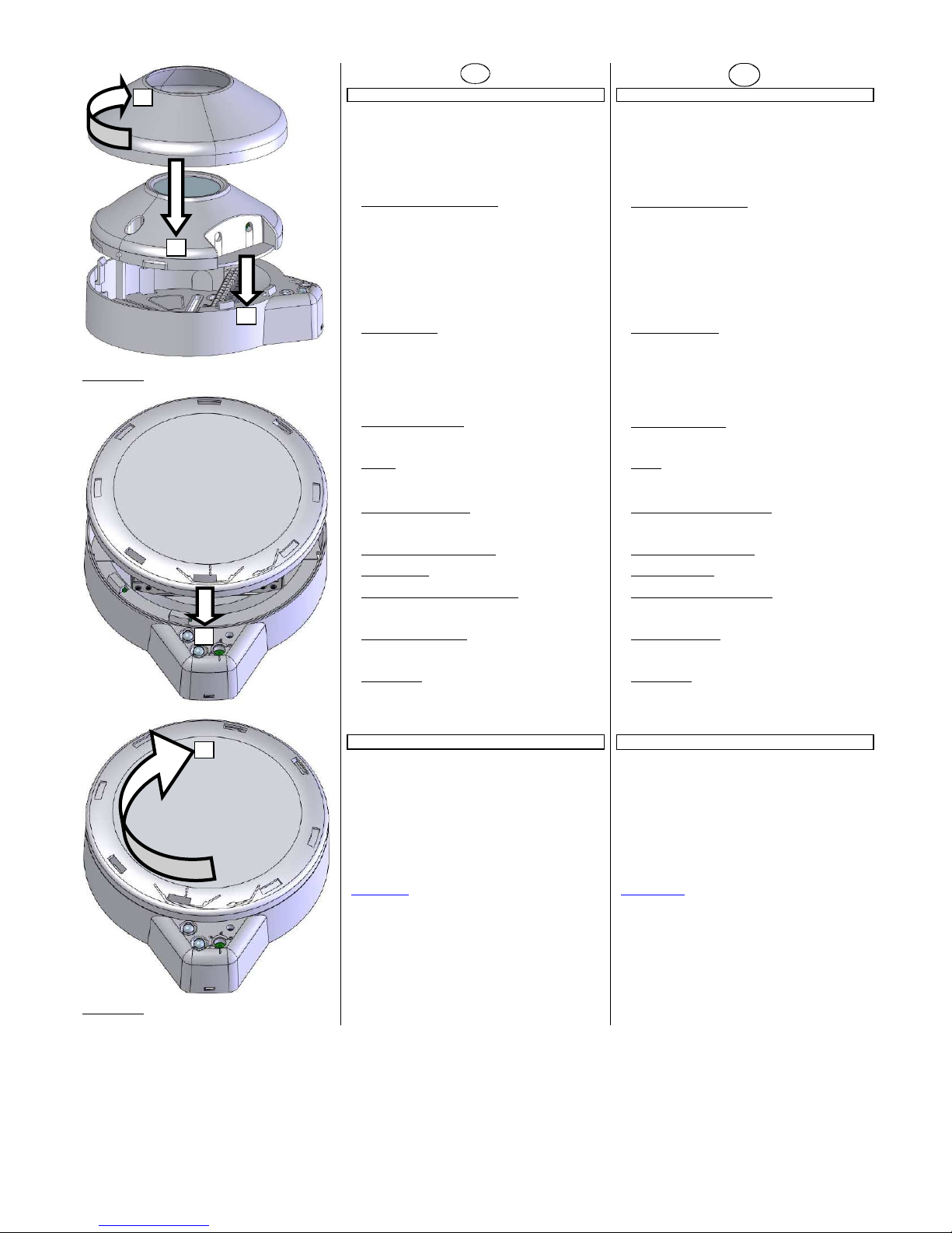
Montage
Allgemeine Beschreibung
Der DALI HIGHBAY ADAPTER ist zum Deckenaufbau und für
Montage auf Leuchtenmodulen bestimmt.
Sensoranschluss / -montage
Der Anschluss des HIGHBAY / VISION Sensors erfolgt über die
integrierte Anschlussklemme. Betrieb nur mit Lichtsensor : Bei
Verwendung ohne HIGHBAY / VISION Sensor ist der beigelegte Blinddeckel zu verwenden (siehe Bild 3).
Einstellung Empfindlichkeit Lichtsensor
Die Empfindlichkeit des Lichtsensors lässt sich zur optimalen
Nutzung des Messbereichs mit einem Potentiometer justieren.
Empfohlene Einstellwerte:
GB
Product and Applications Description
The DALI HIGHBAY ADAPTER is a DALI input device for installation on ceilings or on luminaire modules. The adapter is
made for connection of a light and movement detector to a
higher level DALI – Controller (e.g. OSRAM DALI PRO
CONT-4). The device provides 2 DALI input addresses for light
and movement. The functions for light and movement can be
used independent. Alternatively the integrated lightsensor can
be used without installed movement detector, but then the included cover plate must be mounted.
The device is powered via the connected DALI – wires.
The measurement values of the connected sensor channels
are sent from the DALI sensorcoupler as telegrams via the
DALI wires to the central DALI Controller.
Wiring check:
When DALI voltage is connected a short press to the
SELECT pushbutton (operation only with electrical isolated
tools!), the LED will switch on. The next short press on the SELECT pushbutton will switch off the LED. Otherwise the LED
will switch off after 30s.
Reset to factory default settings:
When DALI voltage is connected a long press (>10s) on the
SELECT pushbutton (operation only with electrical isolated
tools!) the LED will blink for 4s and the sensorcoupler is reset
to factory default settings.
Commissioning
The SELECT pushbutton (operation only with electrical isolated
tools!) can be used for identification of the DALI pushbutton
coupler. For this the commissioning mode of a central DALI
Controller has to be activated.
The LED can can be influenced for setup with a central DALI –
Controller The kind of the signal (flashing, continous light, …)
is dependent on the connected DALI – Controller (see operation manual of the DALI – Controller).
Wiring Example
see figure 2
Location and Function of the Display and Operating Elements
see figure 1
A1 Mains voltage connection L, N, PE + throughwiring
A2 Sensor connections
A3 DALI connection + throughwiring
A4 Lightsensor sensitivity adjustment
A5 SELECT – push button
A6 Lightsensor
A7 Display LED
Installation Instructions
The device may be used for permanent interior installations in
dry locations on ceiling or luminaire modules.
WARNING
• The device must be mounted and commissioned by an
authorised electrician.
• The DALI wiring must not be connected to 230V
• Operation of the SELECT pushbutton and lightsensor sensi-
tivity only with electrical isolated tools
• The prevailing safety and accident prevention rules must be
heeded.
• The device must be mounted with HIGHBAY / VISION Sensor or with cover plate
• When planning and installing electrical installations, the
relevant guidelines, regulations and specifications of the respective country must be observed.
Mounting
General description
The DALI HIGHBAY ADAPTER is intended for use for ceiling
mounting and for luminaire module integration.
Sensorconnection / -mounting
The connection of HIGHBAY / VISION sensor happens via the
integrated connector terminal. Use of only lightsensor : if no
HIGHBAY / VISION sensor is mounted the attached cover plate
has to be used (see figure 3).
Adjustment sensitivity of lightsensor
The integrated lightsensor can be adjusted in its sensitivity by a
potentimeter for optimized usage of measurement window.
Recommended set values:
A1 A2 A3
A4
A5
A6
A7
Page 2
ZNN 2832397 000 00 Seite 2 von 2 page 2 of 2
Bild 3 / figure 3
Bild 4 / figure 4
D
Technische Daten
Spannungsversorgung
• Das Gerät wird über die DALI – Leitung versorgt
Die Spannung richtet sich nach der DALI – Norm 62386.
• Stromaufnahme aus der DALI - Leitung 7 mA
• Stromversorgung HIGHBAY / VISION Sensor 120..277 V
50/60 Hz und Durchverdrahtung über Anschlussklemme
Eingänge
• Eingangssignal-spannung / -strom:
HIGHBAY / VISION Lastkontakt (potentialfreier Kontakt)
Anschlüsse
• 14-polige Steckklemme
• Abisolierlänge 10…11 mm
• Es sind folgende Leiterquerschnitte zulässig:
0,5 ... 2,5 mm² eindrähtig
0,5 ... 2,5 mm² feindrähtig, mit Aderendhülse
0,5 ... 1,5 mm² feindrähtig, ohne Aderendhülse
• Klemmenbelegung: siehe Bild 1 und 2
1,3,5 Netzanschluss 3-polig
2,4,6 Durchverdrahtung Netzanschluß 3-polig
7-8 Sensorkontakt 2-polig
9-10 Sensorstromversorgung 2-polig
11-12 DALI 2-polig
13-14 Durchverdrahtung DALI 2-polig
Mechanische Daten
• Abmessungen (L x B x H):
135 mm x 115 mm x 37 mm
siehe Bild 3
• Gewicht:
ca. 120 g
Elektrische Sicherheit
• Schutzart (nach EN 60529):
IP 20
Umweltbedingungen
• Umgebungstemperatur im Betrieb:
0 ... + 50°C
• Lagertemperatur:
- 25 ... + 70°C
• Relative Feuchte (nicht kondensierend):
5% bis 93%
Zubehör
• Anschliessbare Sensoren :
OSRAM HIGHBAY
OSRAM VISION
• DALI Controller
OSRAM DALI PRO Controller CONT-4
OSRAM DALI PRO Controller CONT-4 RTC
Allgemeine Hinweise
• Die Bedienungsanleitung ist dem Kunden auszuhändigen.
• Ein defektes Gerät ist mit einem Rücklieferschein der zu-
ständigen Vertriebsniederlassung an folgende Adresse zu
senden:
OSRAM AG, Customer-Service-Center (CSC)
Steinerne Furt 62, D-86167 Augsburg
• Bei zusätzlichen Fragen zum Produkt wenden Sie sich bitte
an unseren Technical Support:
℡ +49 (0) 89 - 6213 - 0
(kostenpflichtig)
+49 (0) 89 - 6213 - 2020
www.osram.de
GB
Technical Specifications
Power supply
• The device is powered by the DALI wires
The voltage is based on DALI Standard 62386.
• Current consumed from DALI - line 7 mA
• Supply of HIGHBAY / VISION sensor 120..277 V 50/60 Hz
and throughwiring via connector
Inputs
• Input signal voltage / -current:
HIGHBAY / VISION load contact (floating input)
Connections
• Plug-in terminal with 14-contacts
• Insulation strip length 10...11 mm
• The following conductor cross sections are permitted:
0.5 ... 2.5 mm² single core
0.5 ... 2.5 mm² finely stranded, with connector sleeve
0.5 ... 1.5 mm² finely stranded, without sleeve
• Terminal configuration: see figure 1 and 2
1,3,5 Mains voltage connection 3-poles
2,4,6 Throughwiring mains voltage 3-poles
7-8 Sensorcontact 2-poles
9-10 Sensor supply 2-poles
11-12 DALI 2-poles
13-14 Throughwiring DALI 2-poles
Physical specifications
• Dimensions (L x W x H):
135 mm x 115 mm x 37 mm
see figure 3
• Weight:
approx. 120 g
Electrical safety
• Protection (according to EN 60529):
IP 20
Environmental specifications
• Ambient operating temperature:
0 ... + 50 °C
• Storage temperature:
- 25 ... + 70 °C
• Relative humidity (non-condensing):
5 % to 93 %
Assessories
• Connectable Sensors :
OSRAM HIGHBAY
OSRAM VISION
• DALI Controller
OSRAM DALI PRO Controller CONT-4
OSRAM DALI PRO Controller CONT-4 RTC
General Notes
• The operating instructions must be handed over to the client.
• A faulty device shall be sent with a Return Good Note for
Service provided by the appropriate OSRAM sales office to
the following address:
OSRAM AG, Customer-Service-Center (CSC)
Steinerne Furt 62, D-86167 Augsburg
• If you have further questions concerning the product please
contact our technical support:
℡ +49 (0) 89 - 6213 - 0
(charges apply)
+49 (0) 89 - 6213 - 2020
www.osram.com
1
2
3
1
2
 Loading...