

Page 1
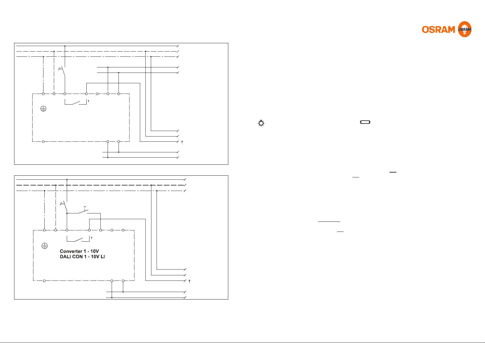
Wiring diagram: DALI CON 1 – 10V LI in DALI mode (operation as converter)
/
L
N
PE
F1
10A
max
123 4567
PE N L T DA DA
DA
DA
DALI
Other DALI units
weitere DALI-Geräte
Converter 1 - 10V
DALI CON 1 - 10V LI
1...10V
NC + -
0...10V
1098
1-10V/0-10V units
1...10V/0...10V Geräte:
PE
ECGs, dimmers,
EVGs, Dimmer,
N
electr. Trans-
elektr.Trafos usw.
Kontaktbelastbarkeit
formers, etc.
beachten !
Check contact rating!
-
0...10V
1...10V
+
Wiring diagram: DALI CON 1 – 10V LI in 1-button mode (Converter as light control unit)
L
N
PE
F
1
S1
10A
max
123 4567
PE N L T DA DA
1...10V
NC + -
0...10V
1098
Subject to change without notice. Errors and omission excepted 02.03.2011 V1.2.
PE
1-10V/0-10V - units:
ECGs,. dimmer s,
N
electronic transformers, etc.
Check contact rating!
-
1...10V/0...10V
+
Operating instructions DALI CON 1 – 10V LI Converter from DALI to 1-10V
Applications and functions
DALI converter CON 1 – 10V LI is a multifunctional unit. On the one hand it is a converter (see DALI
mode) which is accessed digitally via the DALI interface in the same way as a DALI ECG, and on the
other hand it is a lighting controller in its own right (see 1-button mode). With its control output (combined
interface 1-10V/0-10V) and load contact, ECG and electronic transformers can be dimmed and switched
via 1-10V and dimmers via 0-10V.
The characteristic for the control voltage at the output can be set to logarithmic 1-10V (for ECG and electronic
transformers) or to linear 0-10V (for power dimmers) depending on the application. CON 1 – 10V LI is enclosed
in a metal casing for installation in luminaires. A unit with the identical function is also available in an insulated
casing in snap-on design for standard distributor installation (DALI CON 1 – 10V SO).
It is therefore possible to connect DALI with existing 1-10V/0-10V systems, combine the two systems or even set
up separate lighting control systems.
corresponds to: linear characteristic 0-10V corresponds to: logarithmic characteristic 1-10V
DALI mode (operation as converter)
The converter communicates via the DALI interface with the controller (e.g. OSRAM Room Controller DALI RC
BASIC SO). It receives DALI commands from there and also the interface supply voltage. DALI signals are
converted to 1-10V/0-10V signals, including on/off switching via the load contact. The DALI lines (DA/DA) are
connected to the controller for this purpose. The converter is accessed and addressed by the controller in the
same way as a DALI ECG. All the 1-10V/0-10V units connected to the converter are considered as a uniform
group under the address assigned to the converter. Detection of lamp faults and "physical selection"
(deactivation and reactivation of the lamps during system startup) are not supported in the 1-10V/0-10V system.
!In DALI mode, the additional switch input (T) may not be connected!
Behaviour on return of mains voltage in DALI mode (ex factory setting):
Without the controller the load contact is closed and output voltage goes to 10 V (100%). If a controller is
connected, the behaviour is determined by the controller (see controller description).
1-button mode (operation as controller)
In this mode the converter operates as an independent lighting controller with a 1-button switching/dimming
function independently of DALI. It is operated by a switch (make contact/230Vac) which switches from input T to
phase L. To access this mode a long press is needed (enabling the 1-button mode). The converter remains in
this mode until it is reset to DALI mode on receipt of a DALI command via the DALI interface.
!In 1-button mode, the DALI interface may not be connected!
Mode I:
Short press: Switch On/Off, long press: Switch On-brighter/brighter/darker.
The switch on light level is equal to the last level before switch off (automatic memory function).
Mode II:
Short press: Switch On/Off, long press: Switch On-brighter/brighter/darker.
The switch on light level is stored by a double click (= 2 x short press) in switched on state. The storage is
signalised by flashing of the lighting.
Change to mode I: Switch off the light by a short press and make a double click to the push button afterwards.
The converter switches on with 100% light and is now in mode I.
Change to mode II: Make a double click when the light is switched on. The light flashes and the current light
level is stored as switch on level. The converter changes to mode II respectively stays in mode II.
Behaviour on return of mains voltage in 1-button mode:
Switching state and dimming level are restored automatically.
Page 4/4 Operating instructions: DALI CON 1 – 10V LI Operating instructions: DALI CON 1 – 10V LI Page 1/4
Page 2
DALI interface
Interface in accordance with the DALI standard. Current input <2mA DC. Electrical isolation via opto-coupler
from mains and output: basic insulation (no safety extra-low voltage).
The converter does not have an integrated power supply for the DALI interface. The power supply for the DALI
interface has to be part of the DALI controller.
Output (combined interface) 1-10V/0-10V
Interface for controlling 1-10V units (max. -100 mA current sink e.g. for ECG, electronic transformers, etc.)
and/or 0-10V units (max. +5 mA active e.g. for power dimmers, etc.). Electrical isolation from the mains and
DALI: basic insulation (no safety extra-low voltage).
Characteristic switch
Switching option for the characteristic for the control voltage at the output. Linear from 0 – 10V, usually for power
dimmers. Logarithmic from 1 – 10V, usually for ECG and electronic transformers.
Load contact
Internal relay (make contact) not floating. The load contact is connected internally with L. Suitable for direct
on/off switching of small systems. Check the contact load rating. Add an external relay or contactor for larger
systems. On/off switching as function switching.
Switch input
Switch input for operating in 1-button mode. Switching takes place to L (make contact/230Vac). Internal optocoupler to N (mains potential).
Electrical isolation from the output and DALI: basic insulation (no safety extra-low voltage).
Safety and installation instructions
• Power to the units must be switched off before any work is undertaken.
• The units should be installed and tested only by a qualified electrician.
• Wire the terminals as shown in the wiring diagram. Follow the wiring diagrams and any printed
instructions on the unit.
• The relevant safety and accident prevention regulations must be observed.
• The relevant installation instructions must be observed.
• The unit must not be opened or operated without its casing.
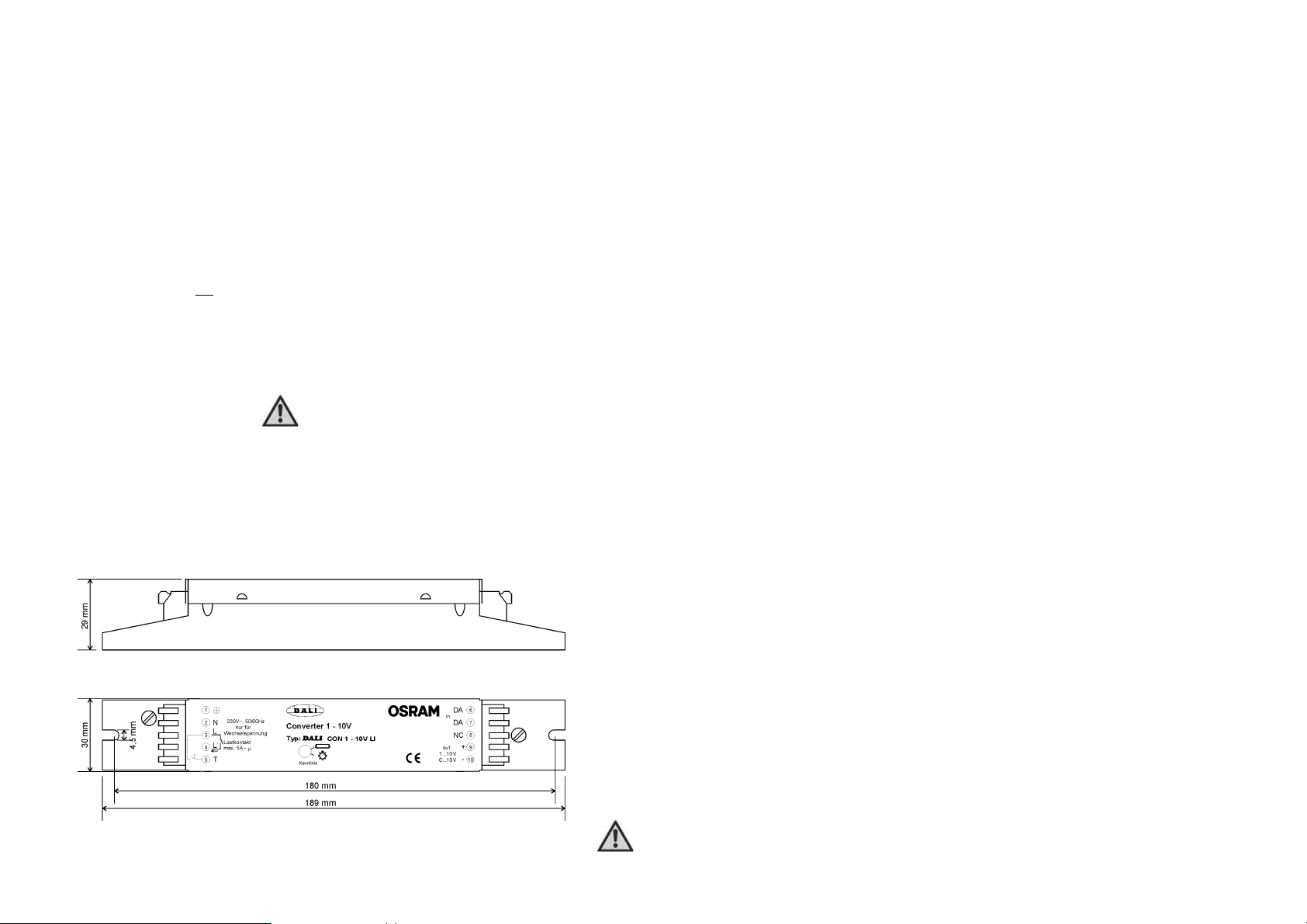
Dimensional drawing:
Usage
of DALI and 1-button operation at the same time is not allowed!
The converter may be damaged or destroyed if wired incorrect!
Page 2/4 Operating instructions for DALI CON 1 – 10V LI Operating instructions for DALI CON 1 – 10V LI Page 3/4
Page 3

Technical data
Designation: Converter from DALI to 1-10V
Type: DALI CON 1 – 10V LI
Mains voltage: 230Vac 50/60 Hz, DC not permitted
Power consumption: approx. 1 W
Fuse protection: External max. 10 A, (load contact is connected internally to L)
Operating temperature: 0°C to 45°C
Protection class/type of protection: I (protective earth)/IP20
Pollution severity: 2 (dry not conductive)
Load contact L` (µ): Relay contact internal (make contact), connected internally with L
Function switching (on/off), no reliable isolation (µ contact gap)
Load capacity L` (µ): max. 10 A~ ohmic load
max. 5A~ ECG load
Output out: 1-10V max. -100mA DC, current sink (approx. 100 ECG or electronic
Control voltage: 0-10V max. +3mA DC (power dimmers –see manufacturers' data–)
Dimming curve: Switchable between: linear 0-10V and logarithmic 1-10V characteristic
DALI interface: Acc. DALI standard, current input <2mA DC, interface non-polarised
Switch input (T): Switch (make contact) for mains voltage (230Vac)
Terminals: Plug-in terminals, single-wire: 0.3 - 1.5 mm
Mains: L, N, PE Terminal no. (3, 2, 1)
Load contact: → L` (µ) Terminal no. (4) internal to L
DALI interface: DA, DA Terminal no. (6, 7) non-polarised
Switch input: T Terminal no. (5)
Output out: 0-10V 1-10V DC +, - Terminal no. (9, 10) polarised
Terminal 8: NC Terminal no. (8) must not
Maximum cable lengths : DALI wire Î see data sheet of the corresponding controller
Push button and 0-10V/1-10V input Î 100m
Cable routes: The relevant wiring requirements governing cable routes, insulation,
fusing and minimum cross-sections must be observed.
Housing: Metal casing for installation in luminaires with screw fastening,
Dimensions: WxHxD=189 x 30 x 29 mm, see dimensional drawing
Weight: approx. 190g
Labelling: CE
Terminal assignment: See wiring diagrams and information printed on unit
EVG HF 1x 18W or 1x36W or
30 St.
EVG HF 2x18W or 2x36W or
20 St.
15 St. QTi DIM 1x14/24 or 1x18 or 1x21/39 or 1x28/54 or 1x36 or 1x58 or
15 St. QTi DIM 3x18 or
10 St. QTi DIM 1x35/49/80 or 2x14/24 or 2x18 or 3x14/24 or 4x18 or
8 St. QTi DIM 2x21/39 or 2x28/54 or 2x35/49 or 2x36 or 2x58 or 4x14/24 or
5 St. QTi DIM 2x35/49/80
transformers– see manufacturers' data–)
2
, fine-wire 0.3 – 1.0 mm
2
be used.
hole spacing 180 mm
Page 2/4 Operating instructions for DALI CON 1 – 10V LI Operating instructions for DALI CON 1 – 10V LI Page 3/4
 Loading...