

Page 1
Page 1 of 59
Talon PRO User Guide
02/26/2020
Page 2

Page 2 of 59
© 2019 Osprey Video. All rights reserved.
Osprey® is the registered trademark of Osprey Video. Microsoft®, Windows® is a registered trademark of Microsoft Corporation. Any other
product names, trademarks, trade names, service marks, or service names owned or registered by any other company and mentioned herein
are the property of their respective companies.
No part of this specification may be reproduced, transcribed, transmitted or stored in a retrieval system in any part or by any means without
the express written consent of Osprey Video. Osprey Video reserves the right to change any products herein at any time and without notice.
Osprey Video makes no representations or warranties regarding the content of this document and assumes no responsibility for any errors
contained herein.
OVERVIEW
Thank you for purchasing the Osprey® Talon PRO video encoder from Osprey Video. This user guide provides step-by-step
instructions for installing and using your new video encoder. For the latest Osprey product information and news, visit our
website at www.ospreyvideo.com.
FEEDBACK:
We greatly value your input. Please direct any questions, comments or support issues to
+1 972 488 7156
PRODUCT DESCRIPTION
The Osprey Talon PRO is a hardware based, small form-factor video encoder designed to be easy to use, portable, and easily
stream 4K, HD or SD content to broadband and mobile networks. It supports 2 simultaneous inputs (3 total) and can stream
HEVC or AVC via an extensive array of transports. Its versatility makes it an excellent Cloud Contribution Encoder. It has an
intuitive web interface for configuration.
Page 3

Page 3 of 59
OVERVIEW 2
FEEDBACK: 2
PRODUCT DESCRIPTION 2
FEATURES 6
SUPPORTED INPUT RESOLUTIONS 6
OPERATING CONTROLS 7
QUICK SETUP 9
Connect the encoder 9
Verify the ip address 10
Connect via a browser 10
WEB UI 13
SYSTEM 14
Device 14
Network 17
Security 18
Date & Time 19
Status LED (advanced) 20
Transports 21
Update 22
Reboot 22
STATUS 23
Page 4

Page 4 of 59
WIFI CONFIGURATION 24
ENCODERS CH1, CH2, CH3 25
Set Encoder Settings 25
Start 25
Destination 25
Video 31
Audio 36
CONFIGURING ENCODER FOR RTMP/RTMPS 37
CONFIGURING ENCODER FOR RTP 39
CONFIGURING ENCODER FOR RTSP 41
CONFIGURING ENCODER FOR UDP 42
CONFIGURING ENCODER FOR FACEBOOK™ LIVE 44
CONFIGURING ENCODER FOR WOWZA CLOUD 48
CONFIGURING ENCODER FOR ZIXI™ BROADCASTER 51
CONFIGURING ENCODER FOR STREAMSPOT 52
CONFIGURING ENCODER FOR SRT 53
CONFIGURING H.264(AVC) ENCODING 54
CONFIGURING H.265 (HEVC) ENCODING. 56
Rate Control: VBR or CBR 56
Quality Mode: Low Latency, Balance, High Quality 56
Interlace Mode: Combined, Separated 57
Page 5

Page 5 of 59
Page 6

Page 6 of 59
FEATURES
• Web-Based/Wireless Configuration and Monitoring
• H.265 encode in resolutions up to 2160p30
• H.264 video from QCIF to 2160p30
• H.265, H.264, MJPEG
• Low Latency
• Fully controllable parameters: resolution, max bitrate, GOP and on-the-fly bitrate control
• Zixi Feeder™ Support
• SRT Support (Modes Supported: Caller & Sender)
• HE-AAC, HEv2-AAC, AAC-LC
• 2 Channels Line Level and Embedded Audio
• Interfaces: HDMI 1.4a input/output, Display Port 1.1 input, 2x 3G-SDI input, Gigabit Ethernet, Re-Clocked
SDI loop through, Line Level Audio input
• Outputs: RTP, RTSP, MPEG-2 TS over UDP, RTMP, RTMPS, Zixi Feeder, SRT, and TSRTP
• MP4 & TS File Recording
• 4SDI stereo pairs supported
• Support for Dual HD SDI mode or HD SDI and a HDMI input
• Audio Resampling support
• Live Video Preview in the web browser
• ROI crop encode
• Supports unicast and multicast streaming
• 1x USB 2.0 interface for local storage
• 1x Micro-SD card interface for local storage
• Operating System: Embedded Linux
• Redundant Power Supply
SUPPORTED INPUT RESOLUTIONS
HDMI (TV): 2160p30, 1080p60, 1080p59.94, 1080p50, 1080p30, 1080p29.97, 1080p25, 1080p24, 1080p23.98, 1080i30, 1080i29.97, 1080i25,
1080i24, 1080i23.98, 720p60, 720p59.94, 720p50, 720p30, 720p29.97,720p25, 720p24, 720p23.98, 576p50, 480p60
NOTE: HDMI 1080I MODES REQUIRE OPERATING MODE HD_INTERLACED IN SYSTEM SETUP TAB
HDMI (PC): 3560x1760 @ 30fps, 2560x1600(WQXGA) @ 25fps, 2560x1600 @ 30fps, 2560x1600 @ 50fps, 2560x1600 @ 60fps, 1920x1200 @
60fps, 1680x1050 @ 60fps, 1600x1200 @ 60fps, 1600x900 @ 60fps, 1440x900 @ 60fps, 1400x1050 @ 60fps, 1280x1024 @ 60fps, 1280x1024
@ 75fps,1280x1024 @ 85fps, 1280x960 @ 60fps, 1280x800 @ 60fps, 1280x768 @ 60fps, 1280x768 @75fps, 1280x768 @ 85fps, 1280x720 @
75fps, 1280x720 @ 85fps, 1280x600 @ 60fps, 1152x864 @ 60fps, 1024x768 @ 60fps, 1024x768 @ 70fps, 1024x768 @ 75fps, 1024x768
@85fps, 960x600 @ 60fps, 848x480 @ 60fps, 800x600 @ 60fps, 800x600 @ 72fps, 800x600 @75fps, 800x600 @ 85fps, 640x480 @ 60fps,
640x480 @ 75fps, 640x480 @ 85fps, 640x360 @ 60fps
SDI:1080p60, 1080p59.94, 1080p50, 1080p30, 1080p29.97, 1080p25, p1080p24, 1080p23.98, 1080i30, 1080i29.97, 1080i25, 1080i24,
1080i23.98, 720p60, 720p59.94, 720p50, 720p30, 720p29.97, 720p25, 720p24, 720p23.98, 576i25, 480i30, 480i29.97
Page 7
Page 7 of 59
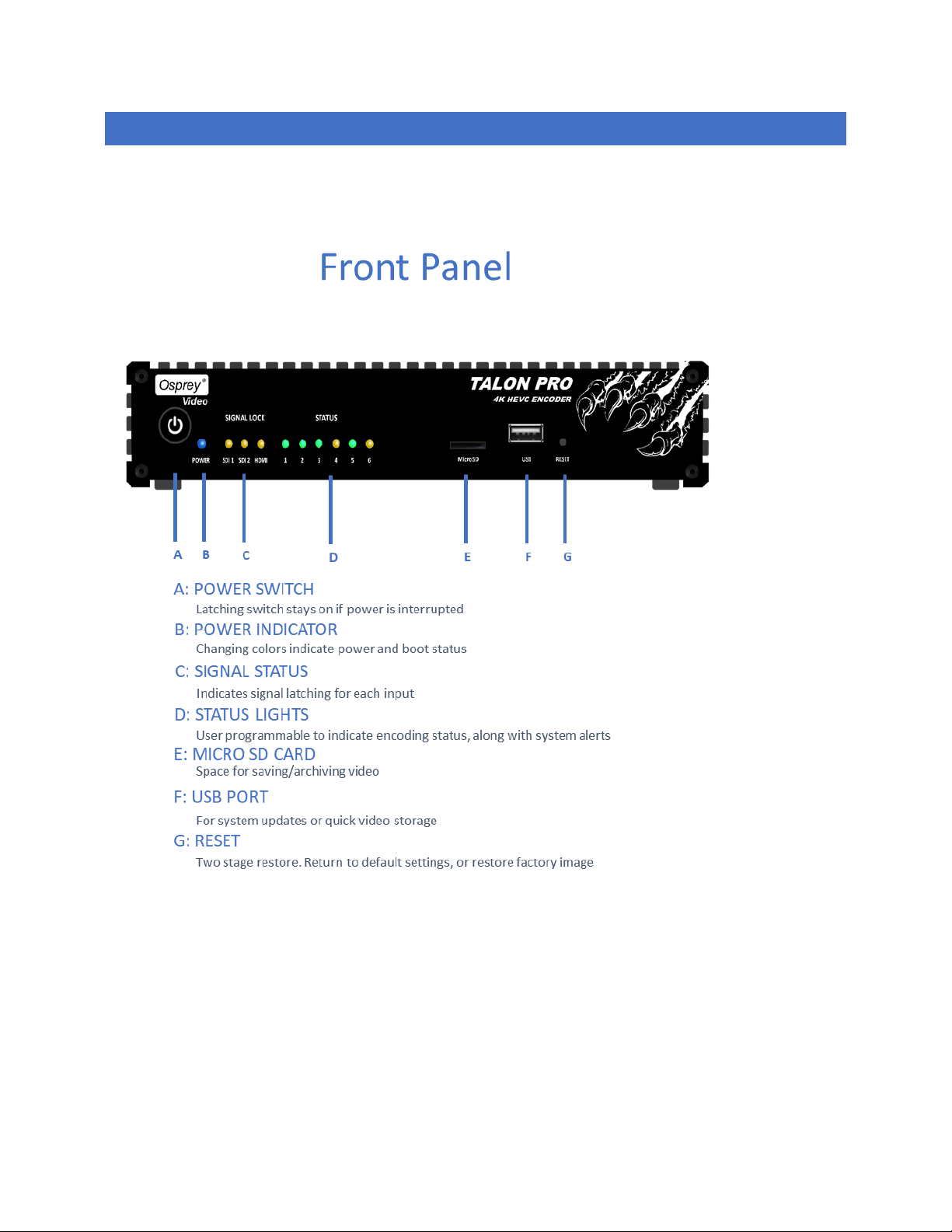
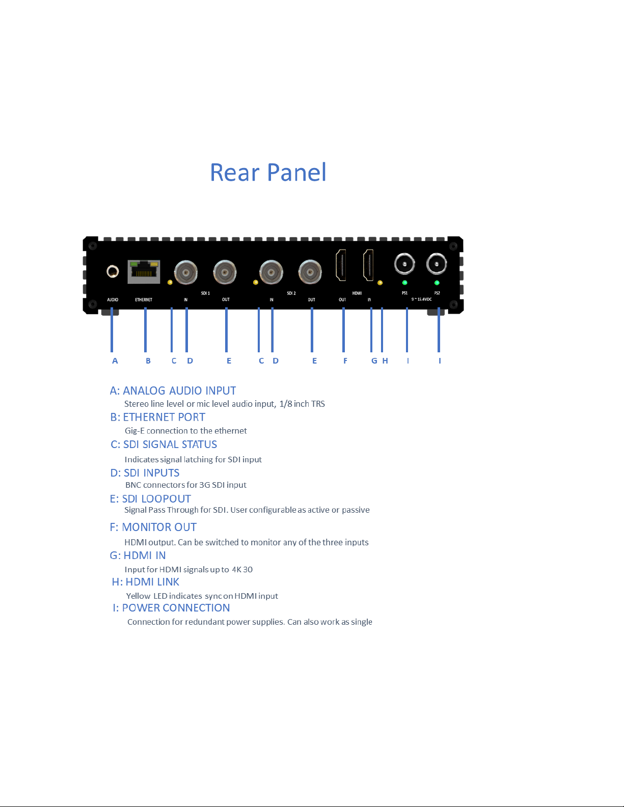
OPERATING CONTROLS
Page 8
Page 8 of 59
Page 9
Page 9 of 59
QUICK SETUP
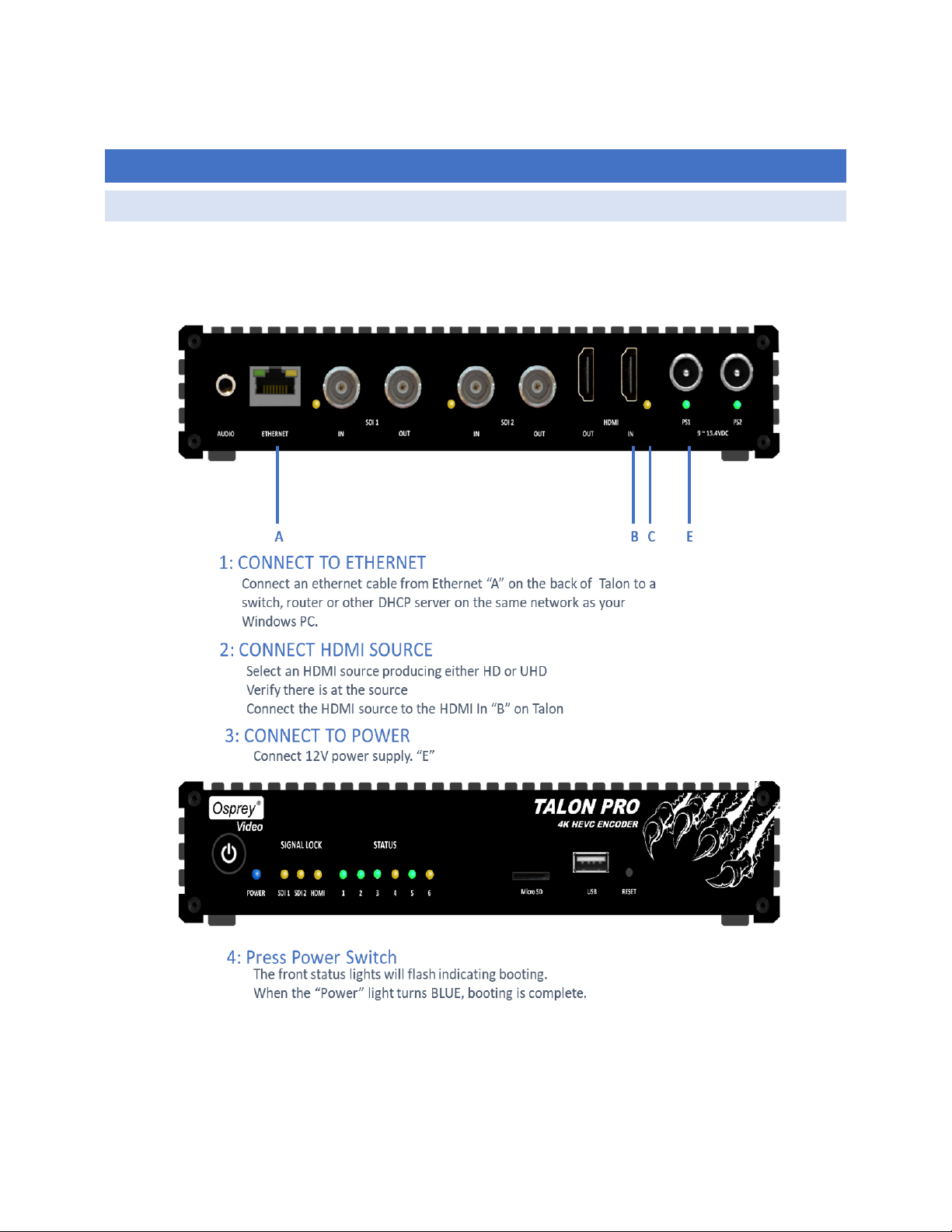
CONNECT THE ENCODER
Page 10
Page 10 of 59
VERIFY THE IP ADDRESS
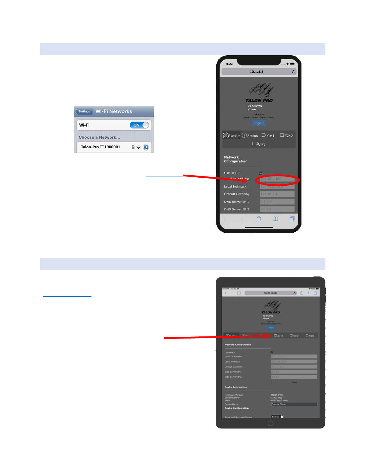
1. Use a smart phone
2. Turn on wireless networking
3. Connect to wireless network “Talon-Pro (your Talon serial
number) with password “0spr3yT@l0n”
4. Using the phone’s browser, go to http://10.1.1.1
5. Read the Local IP Address of the Talon Here:
CONNECT VIA A BROWSE R
Using a PC, MAC or Tablet that is on the same network as the Talon,
enter the IP address you found above. EXAMPLE
http://192.168.2.21
Select a Channel
Page 11
Page 11 of 59
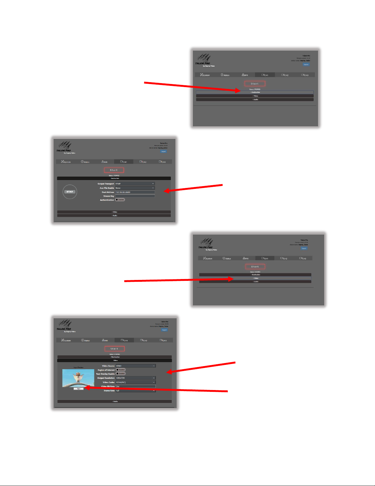
Click on the
Destination Bar
Enter Destination Info
Click on the Video Bar
Video Settings
Video Preview
Page 12
Page 12 of 59
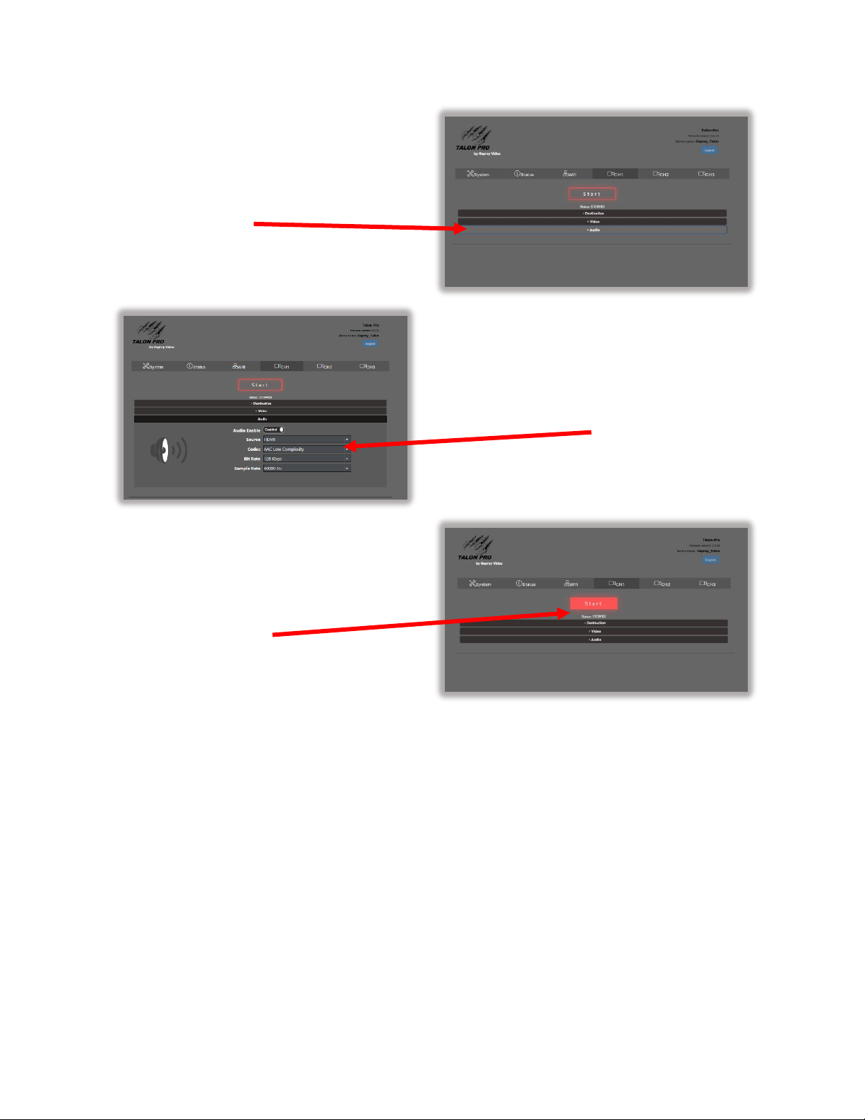
Click on the Audio Bar
Enter Audio Info
Select START
Page 13
Page 13 of 59
WEB UI
The Web UI can be reached from any modern browser that has access to the network where the Talon PRO
resides. It opens at a landing page that displays information regarding the global system settings. The
informational tabs are SYSTEM, STATUS, and Wi-Fi. Most of the global settings are found beneath the SYSTEM tab.
Before moving on to encoder configuration, familiarize yourself with the basic SYSTEM settings.
Page 14
Page 14 of 59
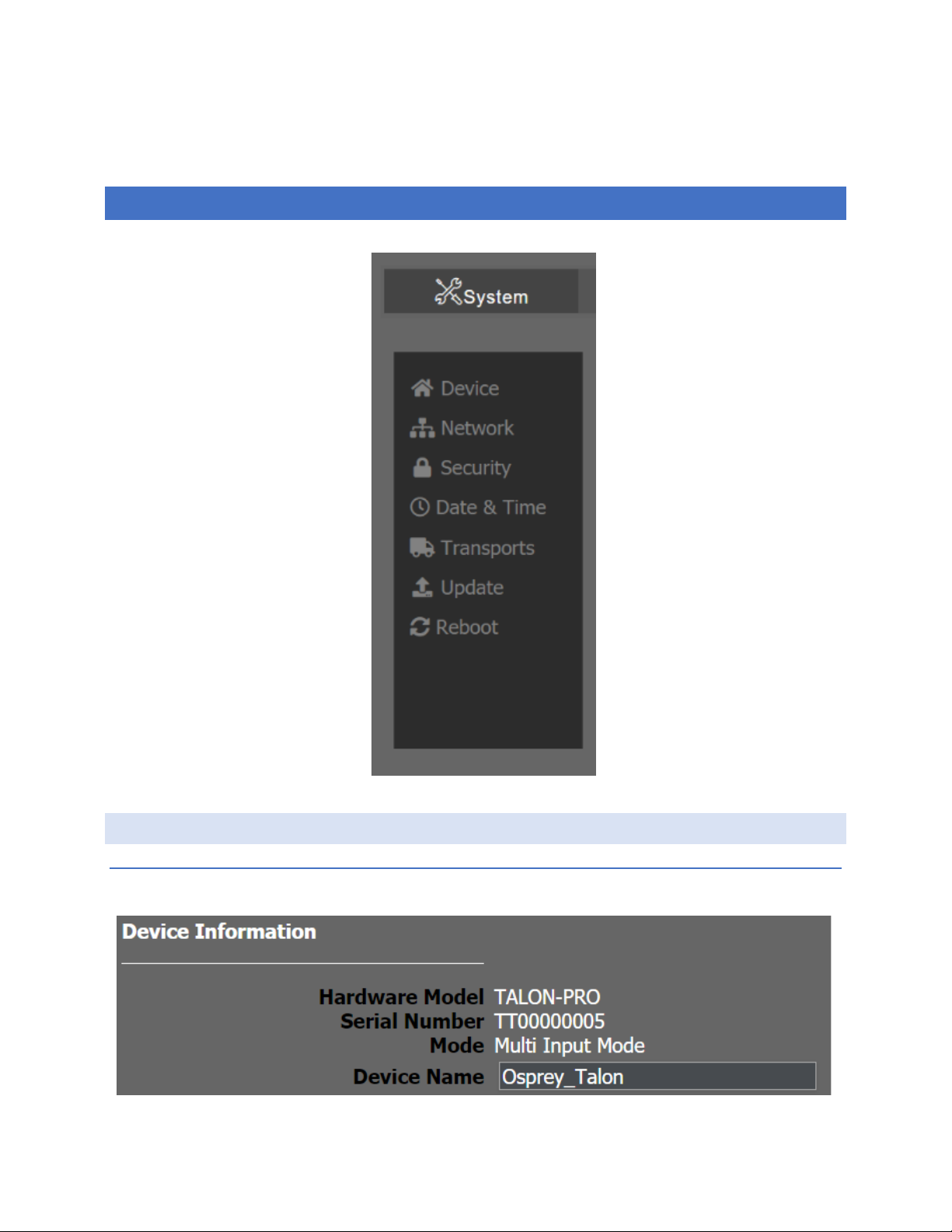
SYSTEM
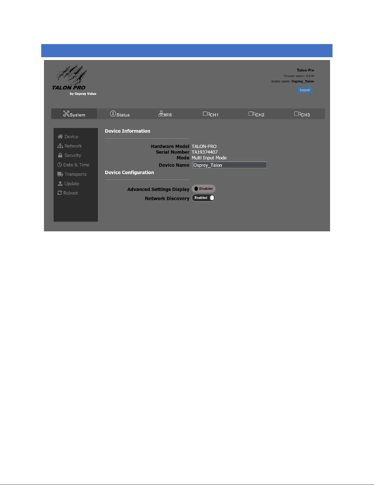
The System tab has device information along with global system settings.
DEVICE
DEVICE INFO RMATION
Page 15
Page 15 of 59
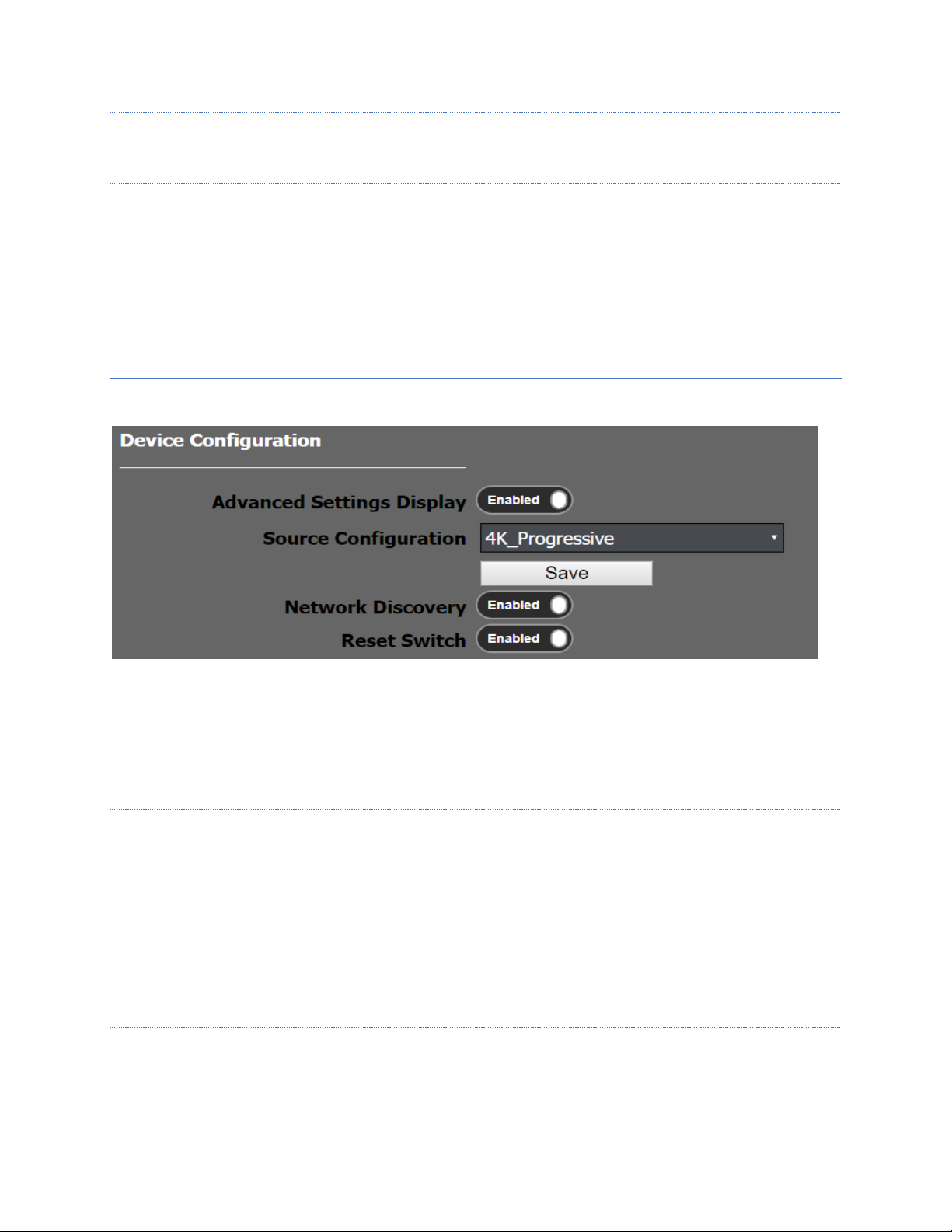
HARDWARE MODEL
TALON-PRO
SERIAL NUMBER
The Device Serial Number is used by other parts of the system to identify this encoder and the features associated
with it. It cannot be changed by the user.
MODE
Indicates whether the encoder is in Multi Input mode, or Single Input mode. The default is Multi Input. This
changes to Single Mode if, in the Streaming Options category below the Ultra Low Latency option is enabled.
DEVICE CONFIGURATION
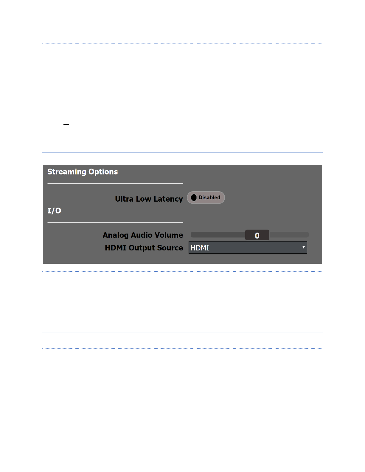
ADVANCED SETTINGS DISPLAY
The basic encoding settings are enabled by default For greater customization, additional settings may be accessed
by enabling Advanced Settings.
If Enabled, the advanced settings become visible in the UI. The default is Disabled.
SOURCE CONFIGURATION (ADVANCED)
Specifies which source combination is available. Options are:
1. 4K30 HDMI + SDI1
2. SDI1 + SDI2
3. HDMI + SDI1
Options 1 and 2 only support progressive inputs. Option 3 supports 3G HDMI, and SDI as well as interlaced
SDI inputs.
Changing this setting requires a reboot.
NETWORK DISCOVERY
When Enabled this allows the encoder to announce its presence on the network so that it can be discovered by the
configuration utility. The default is Enabled.
Page 16
Page 16 of 59
RESET SWITCH (ADVANCED)
If this is Enabled, there is a recessed button on the front of the encoder that lets the user reset the system back to
factory settings. You may Disable this to prevent unauthorized resetting of the device. The default setting is
Enabled.
To clear all encoder settings, press and hold the reset button. The six Status LEDs will turn green one at a time.
When they all flash at once, release the button and the system will reboot. All encoder settings will be removed.
Non encoder settings will remain.
To clear all system settings and restore to the last system image, press and hold until the six Status LEDs light
green. Continue to hold the button until the six all change to yellow. When the button is released the encoder will
reboot and all settings will be returned to their factory defaults. This includes network settings.
STREAMING O PTIONS (ADVANCED)
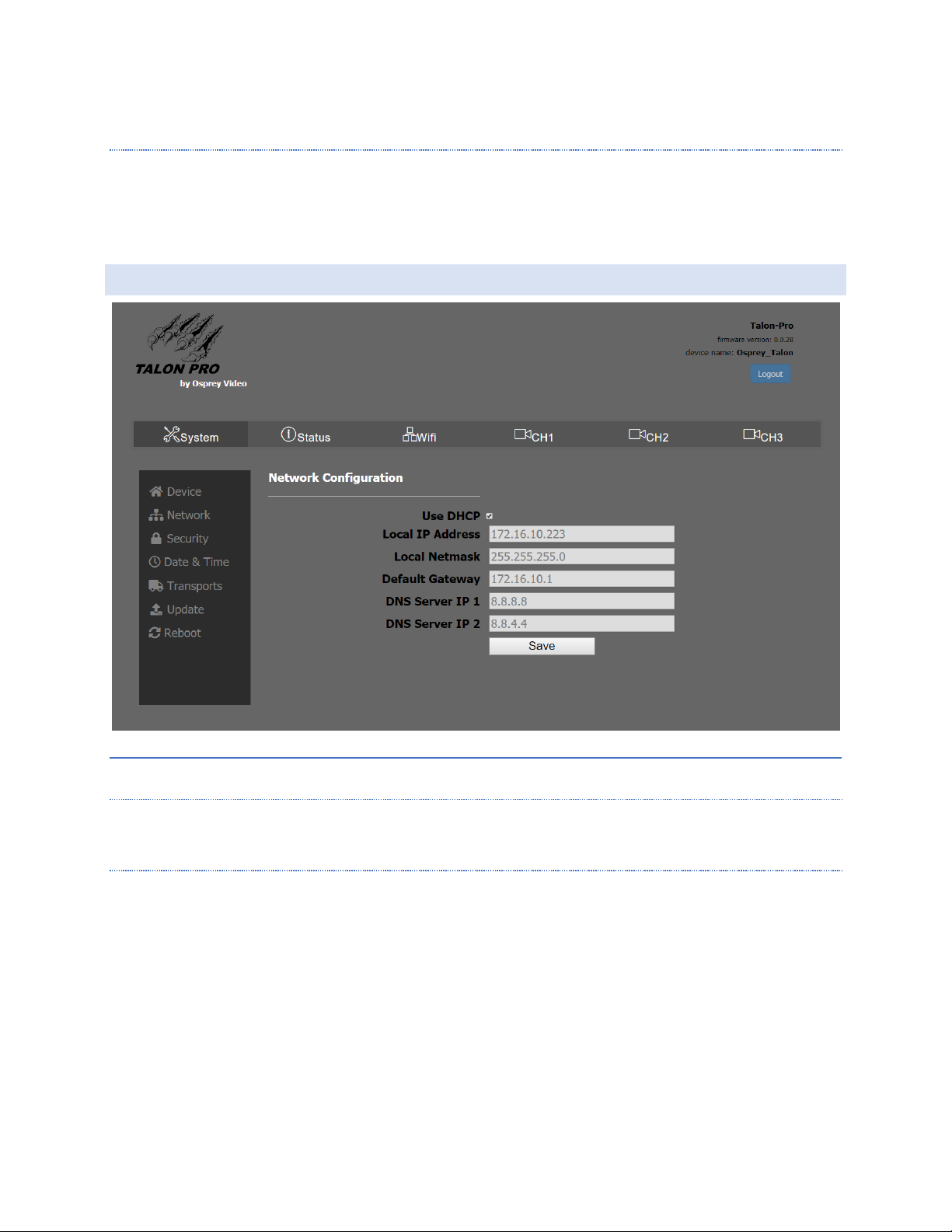
ULTRA LOW LATENCY
Default setting is Disabled. When Enabled reduces the overall encoding latency of Talon. To do this the device runs
in “Single Input Mode”. Only one input can be used. This setting can result in degraded video quality and should
not be used for regular streaming.
Changing this setting requires the system to reboot. Any encoders that are running will be stopped.
I/O (ADVANCED)
ANALOG AUDIO VOLUME
This slider adjusts the incoming volume of a source that is connected to the analog audio input on the front panel.
Moving the slider to the right will increase the volume up to 12db. Moving the slider to the left will pad a loud
input up to 12db.
Page 17
Page 17 of 59
HDMI OUTPUT SOURCE
Be default the HDMI output on the rear of the Talon displays the signal from the HDMI input. Here you may select
any other source and display it on the HDMI output for monitor purposes. This selection can be changed while
Talon is encoding without effecting the streaming output.
NETWORK
NETWORK CONFIGURATION
DHCP
By default, Talon is set to receive an IP address automatically via DHCP.
STATIC IP
If you do not wish to use DHCP you may uncheck the box and assign a static address manually. Be certain that the
static IP you set is valid before rebooting. Failure can cause Talon to become inaccessible to the web UI. When that
occurs, you can use Talon’s wireless access point to reset the address or use the reset button on the front of the
device to restore the system to original default settings.
Page 18
Page 18 of 59
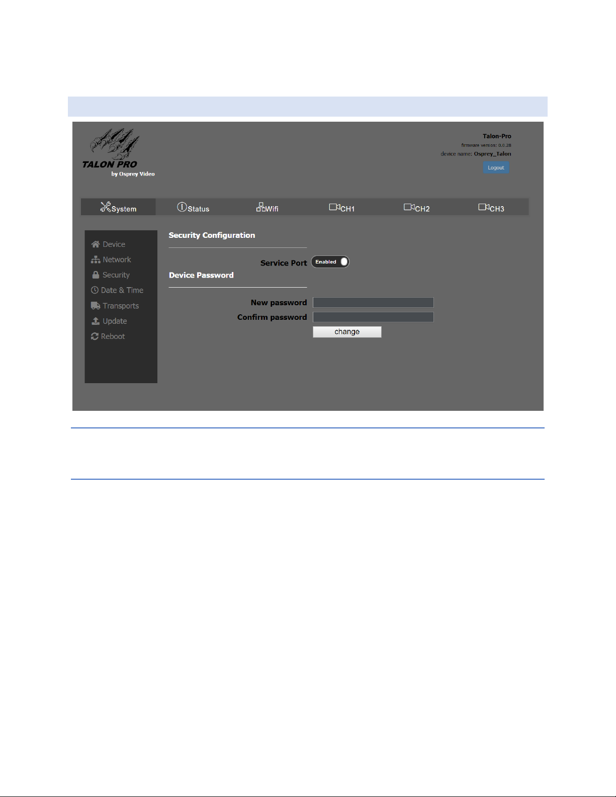
SECURITY
SERVICE PORT
To turn off the hardware service port set this to “Disabled”.
DEVICE PASSWORD
You can create a password for the web UI here. If no password is set no login is required. Username is “admin”
and cannot be changed.
Page 19
Page 19 of 59
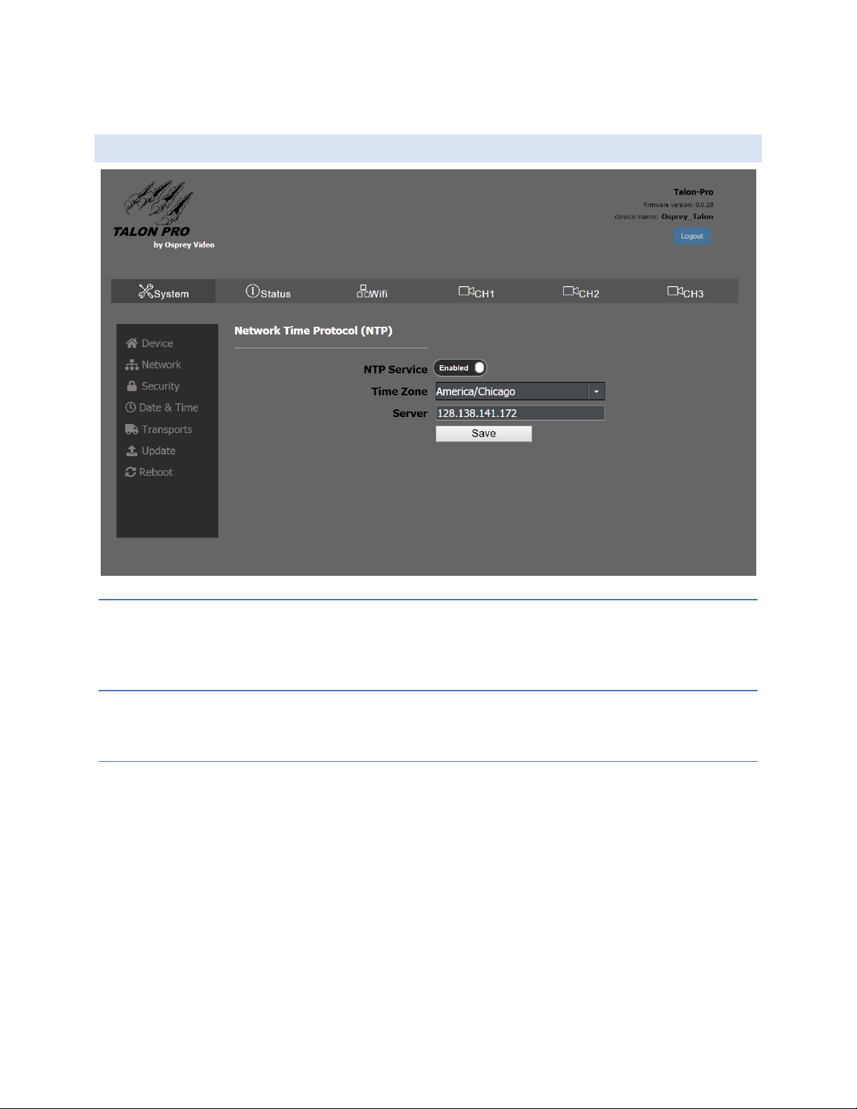
DATE & TIME
NTP SERVICE
Talon supports Network Time Protocol (NTP) for clock synchronization on computer networks. It is enabled by
default.
TI ME ZONE
For NTP purposes, set this to your local time zone. (continent/location)
SERVER
By default, the server address is set for the outside NTP server. If your network uses a local timeserver, you may
input that address here.
Page 20
Page 20 of 59
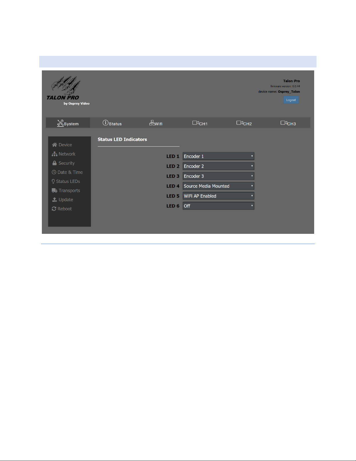
STATUS LED (ADVANCED)
STATUS LED INDICATORS
On the front of the Talon PRO are six user configurable LEDs. These can each be set to light up under a specified
condition. The options are:
• Encoder 1: indicates Encoder 1 is active
• Encoder 2: indicates Encoder 2 is active
• Encoder 3: indicates Encoder 3 is active
• Source Media Mounted: indicates if a USB drive or SD card has been recognized by the OS
• WiFi AP enabled: indicates that the WiFi access point is on.
Page 21
Page 21 of 59
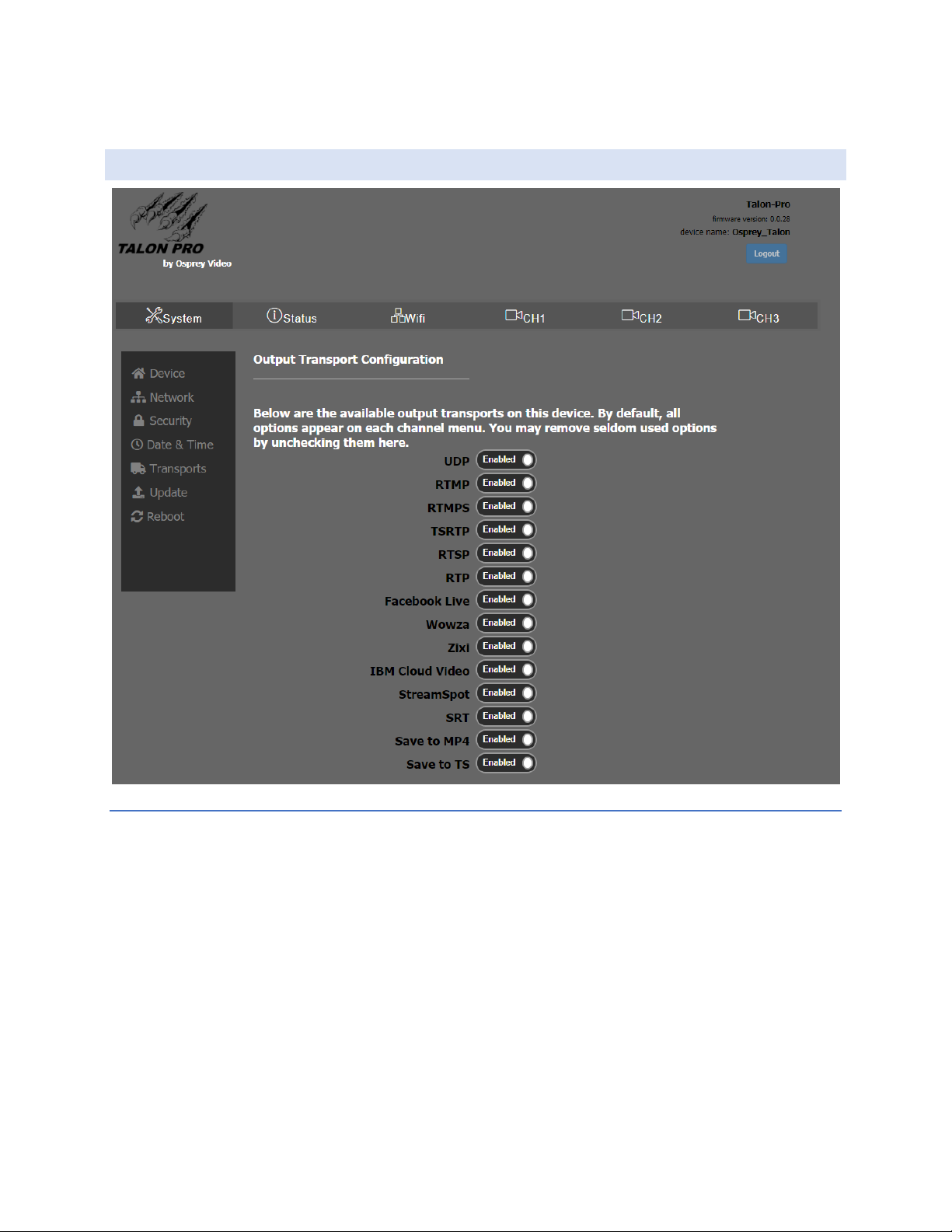
TR ANSPORTS
OUTPUT TRANSPORT CONFIGURATION
There are 14 available transport options that are enabled by default. To simplify setup, some admins prefer to
remove unused transports from the encoder menu. Disabling any of them here prevents them from appearing in
the encoder configuration dialog.
Page 22
Page 22 of 59
UPDATE
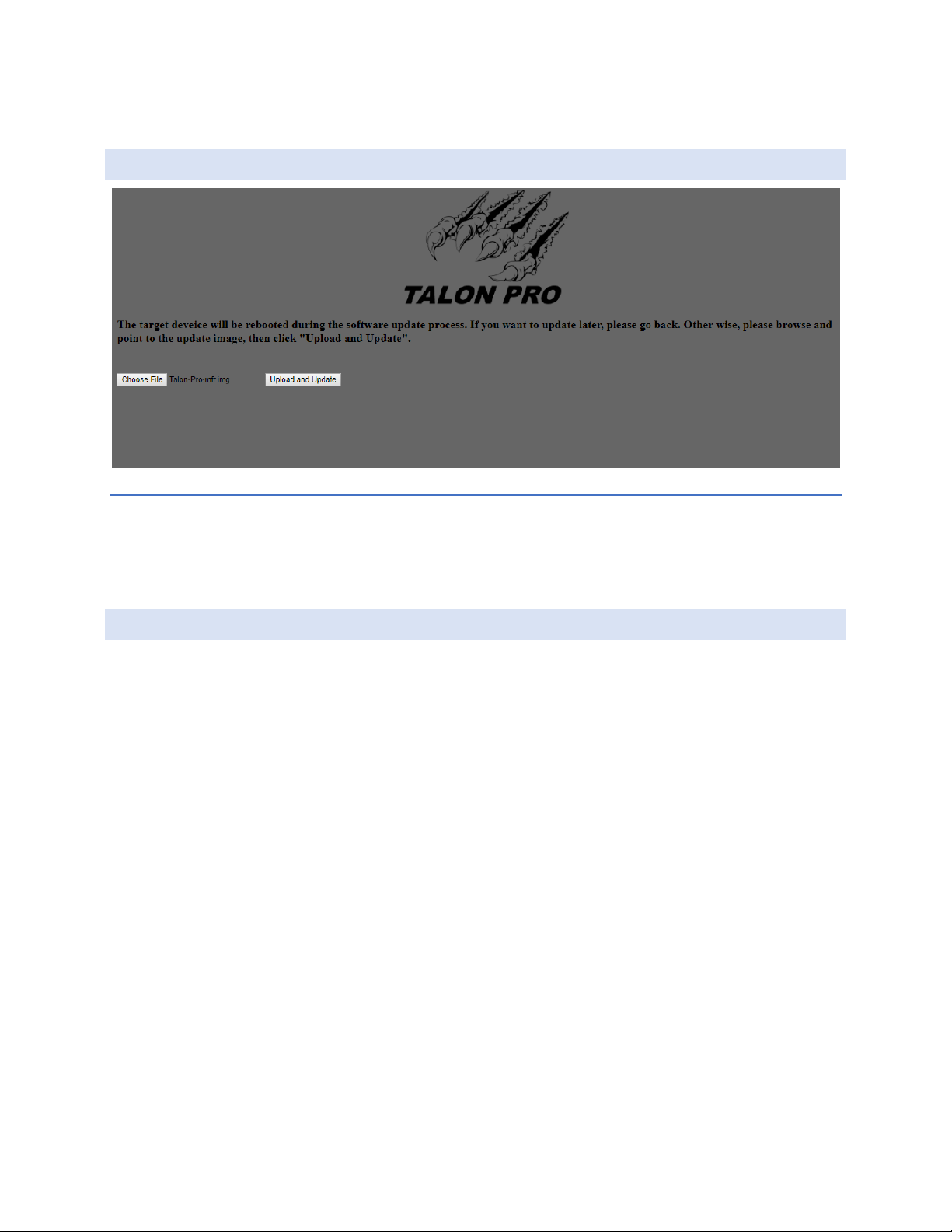
UPDATE PRO CEDURE
Updates to Talon are made available via the web. If an update is necessary, download it from the Osprey website
and save it to your local PC. From Talon’s update page, click “Choose File” and choose the downloaded file from its
location on your PC. Then click “Upload and Update”.
REBOOT
To Reboot Talon without having to power cycle the encoder, click Reboot, and then click “Reboot Now” on the
dialog box that appears. You will be unable to access the encoder from the UI while it is rebooting. The reboot
process usually takes less than 30 seconds. The front panel LEDs will flash until the boot sequence is completed.
Page 23
Page 23 of 59
STATUS
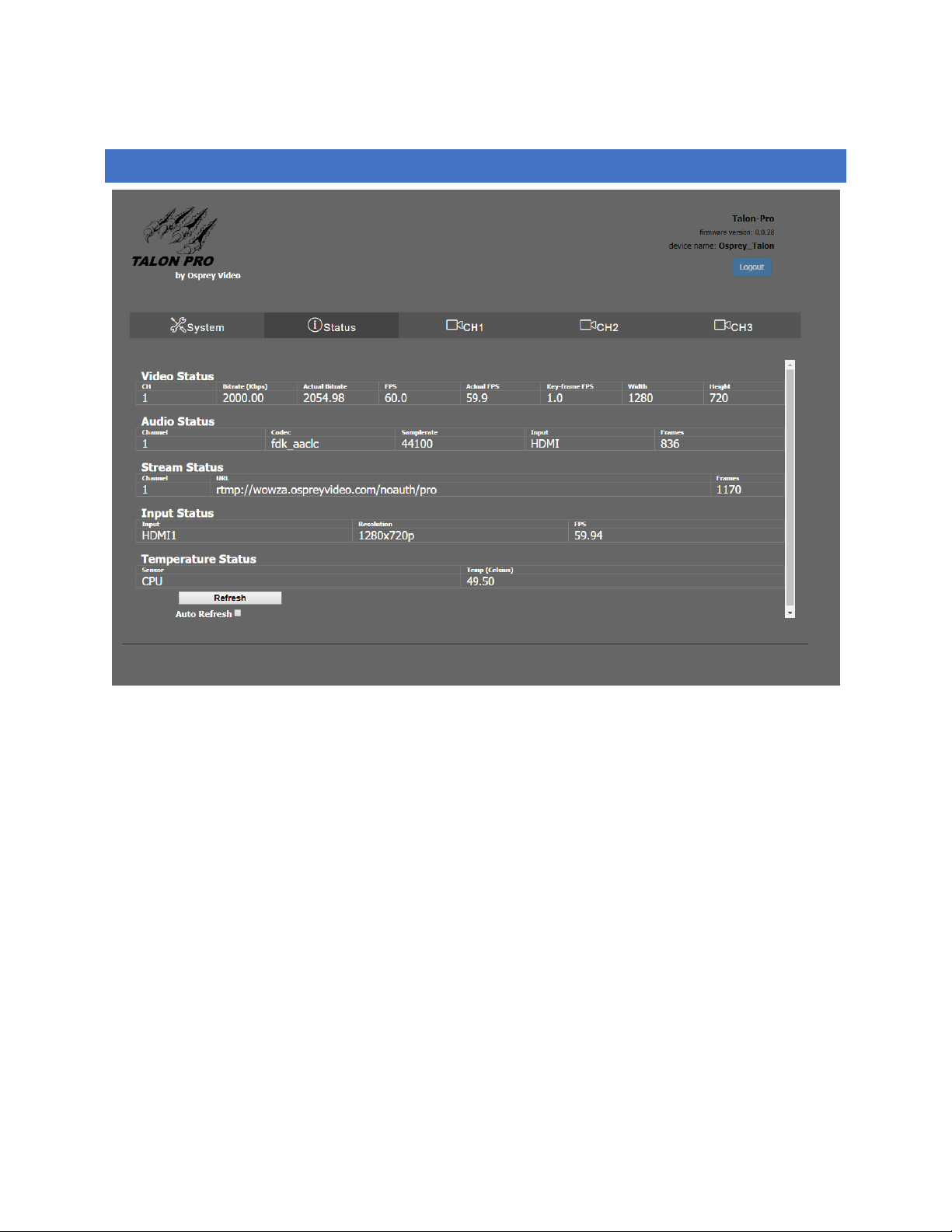
This tab provides a status overview of all inputs and all streams, along with CPU Temperature status from a single
page. The refresh button updates the page when pressed. For continuous updates select “Auto Refresh”
Page 24
Page 24 of 59
WIFI CONFIGURATION
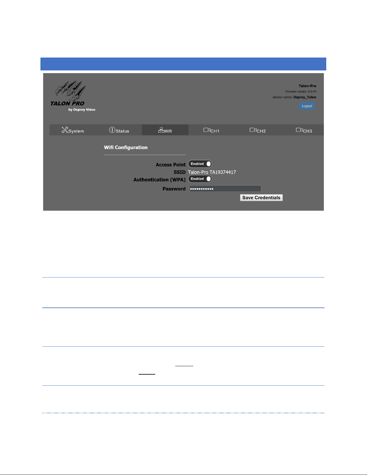
The Wi-Fi on the Talon is an access point for configuration only. It will not support WiFi streaming. To access your
Talon, select the Access Point whose SSID is the same as the Serial Number. Once selected, use the password
“0spr3yT@l0n” to connect to the access point. In your browser, connect to the IP 10.1.1.1 to reach the Web UI
and determine the IP address of your Talon. You can continue to use the access point to configure your encoders,
or you can use the IP address to connect with a browser from a PC. For complete instructions see the Talon Quick
Start Guide.
ACCESS POINT
The Talon Wi-Fi access point is enabled by default. To turn off the Access Point, select “Disabled”
SSID
The SSID is “Talon-Pro” followed by the serial number of the Talon. You can distinguish multiple encoders in the
same vicinity by the serial number.
AUTHENTICATION
Authentication is turned on by default. If it is disabled anyone who tries to connect can do so without a password.
It is recommended that authentication always be enabled.
PASSWORD
The default password for WiFi is 0spr3yT@l0n This is the same for every Talon.
NOTE: FOR SECURITY, YOU SHOULD CHANGE THE PASSWORD AFTER FIRST SETUP.
Page 25
Page 25 of 59
ENCODERS CH1, CH2, CH3
SET ENCODER SETTINGS
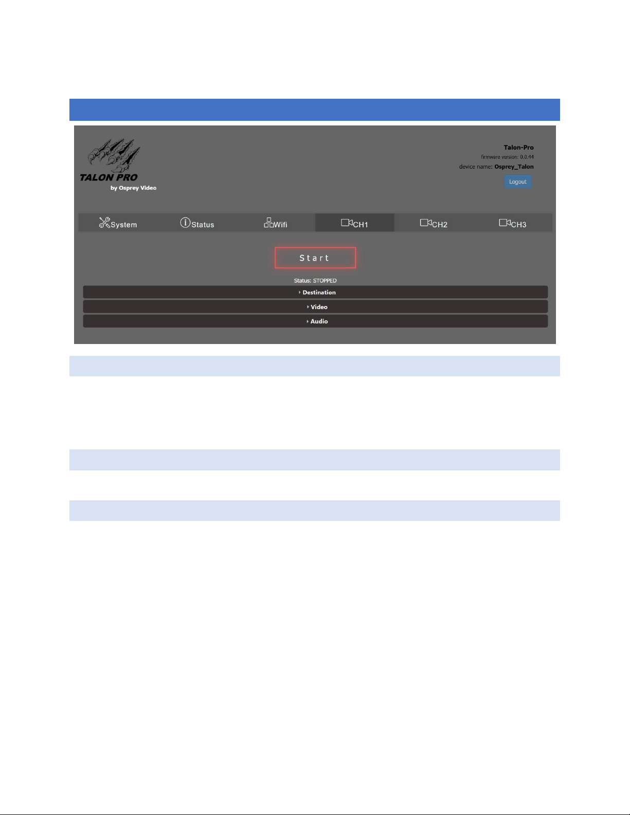
All settings for creating a stream can be found by clicking on the tab for the individual encoders labeled CH1, CH2
and CH3. To configure an encoder, it is best to start first with the “Destination” ribbon. Each type of encoder
transport has configuration options that are unique to that encoder type. By selecting the “Output Transport” first,
these options are activated on the subsequent “Video” and “Audio” ribbons.
START
All encoder options should be configured before clicking on the “Start” button.
DESTINATION
The Destination ribbon is where you select the transport type and location of the video stream you are creating.
The selection of the Output Transport will change the options available on the Destination page, as well as the
Video selections found on the next ribbon. For that reason, it is recommended that you start all configuration at
the Destination tab.
Page 26
Page 26 of 59
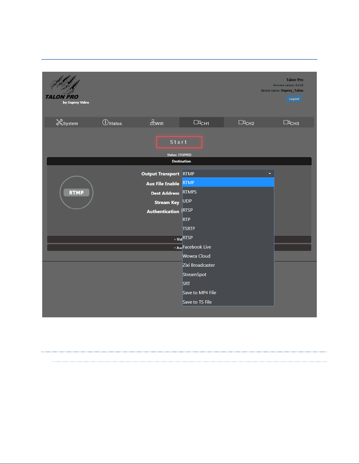
OUTPUT TRANSPORT
Output Transport is where you select the format of the encoded IP stream. Selecting RTMP will present a different
set of options than selecting UDP. As each selection is different, refer to the Encoder Configuration Page in the
User Guide for each Output Transport.
NOTE:
• IF UDP IS SELECTED, DON’T FORGET TO CHECK THE VALUE OF TS RATE TO MAKE SURE IT IS IN LINE
WITH EXPECTATION.
• RTP REQUIRES AN SDP FILE FOR THE RECEIVER THAT CORRESPONDS WITH THE VIDEO CODEC USED.
• RTSP REQUIRES THE USE OF THE RTSP URL.
• ZIXI CAUSES STREAMING VIA ZIXI FEEDER™ TO A ZIXI RECEIVER™ COMPATIBLE DEVICE.
Page 27
Page 27 of 59
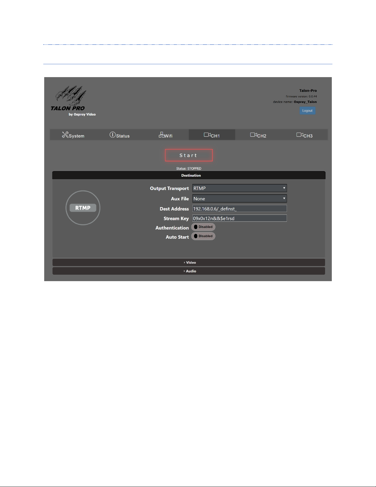
AUX FILE
The AUX FILE menu is for creating and saving a file at the same time as the encoder is streaming Options are None,
TSfile or MP4file. Some transports do not support all options. The option will be grayed out if it is not supported by
the transport you have suggested.
Page 28
Page 28 of 59
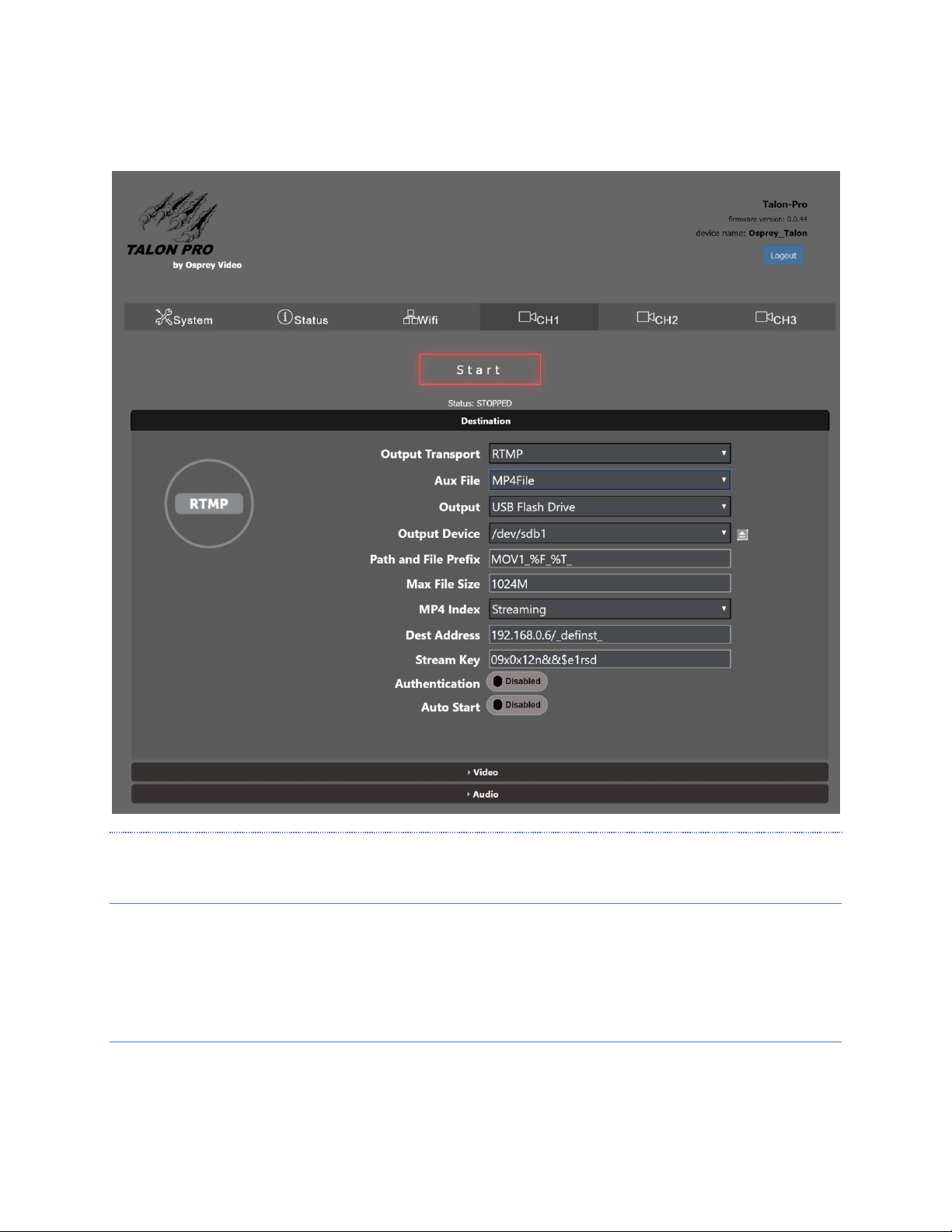
An Aux File can be saved simultaneously with RTMP, RTMPS, UDP, RTSP, RTP, TSRTP TRSP and SRT. When “None is
selected the menu appears as above. When TSfile or MP4file are selected, the option menu appears.
NOTE: SPECIAL TRANSPORTS LIKE WOWZA CLOUD AND FACEBOOK LIVE DO NOT ALLOW FOR
SIMULTANEOUS FILE SAVING.
OUTPUT
If MP4File or TSFile are selected, Multiple file related dialogs appear.
“Output” allows selection of “USB Flash Drive”, which provides access to an attached USB stick or SD Card, or
“Network Share”
OUTPUT DEVI CE (USB FLASH DRIVE ONLY)
Page 29

Page 29 of 59
If “USB Flash Drive” is selected the “Output Device” dialog appears. Here you can select from devices that have
been mounted by the OS. There is a Unmount icon to finish and unmount a device. Always unmount a USB Flash
Drive before removing it to ensure that the files have finished.
NETWORK SHARE (ONLY WHEN “NETWORK SHARE” IS SELECTE D IN “ OUTPUT”
IRL for network share i.e //192.168.1.99/ShareName
DOMAIN
Domain name for authentication to the network share
USERNAME
Account username with permission to access the network share
PASSWORD
Password to account referenced above
PATH AND FILE PREFIX
The path to the file location for the encoded file. i.e. FolderName/SubFolder.
This is followed by the name for the saved file.
DECODER URL
For UDP, RTP and TSRTP this is the URL to set your decoder or player to in order to play the stream.
MULTICAST IP (RTS/UDP ONLY)
Specifies the default multicast address for the video RTP stream
Default is 255.1.2.3
DEST ADDRESS
IP address for the destination of the encoded stream.
STREAM KEY
Stream Key or stream name to be appended to the Destination Address.
DESTINATION PORT
The destination port that the encoder is streaming to.
Range is 0-9999. Default is 8600
Page 30

Page 30 of 59
MAX FILE SIZE
The maximum size for the file before creating a new file.
Recommendation is 1024M
MP4 INDEX
Options are for regular file saving, or formatted for streaming.
DECODER UR L (RTSP/UDP/TSRTP ONLY)
Shows the url for use in VLC (and others) to decode the stream.
AUTHENTICATION
Enable authentication when your RTMP stream requires a username and password.
USER
Username for stream authentication
PASSWORD
Password for the stream account
AUTO START
When enabled, this causes the stream to start when Talon is rebooted. Useful to ensure that the stream restarts
without intervention in the event of accidental power outage.
Page 31
Page 31 of 59
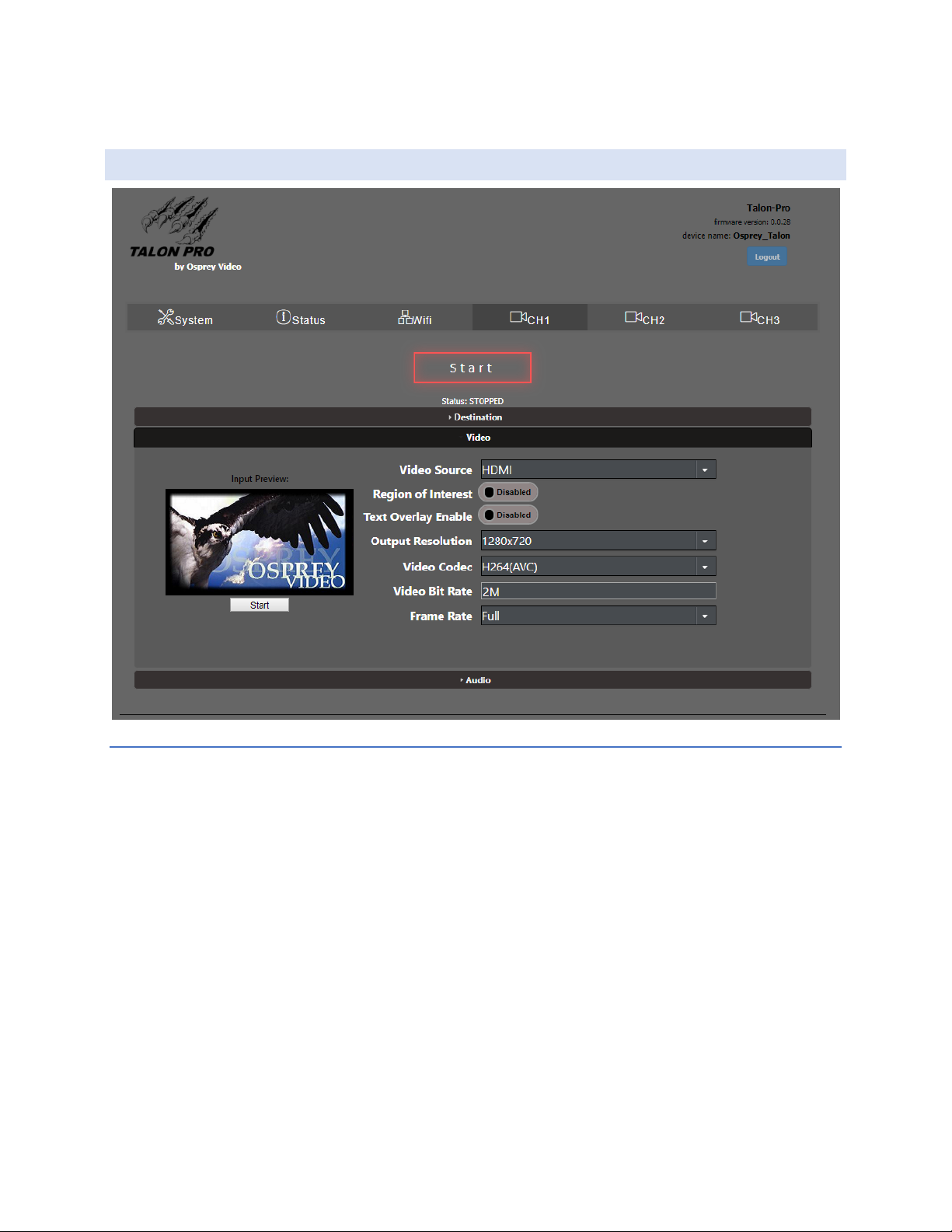
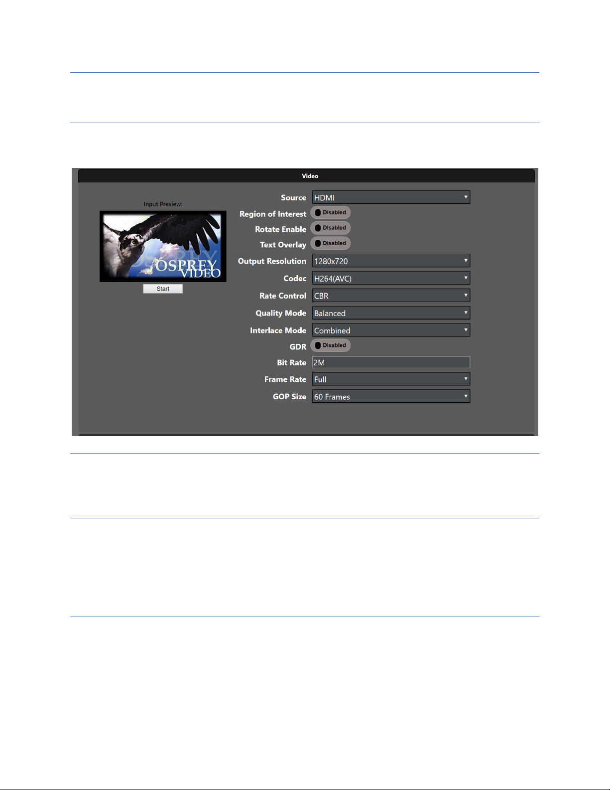
VIDEO
SOURCE
Select video source from the pull-down. Options change depending on which mode was selected under
System/Device/Device Configuration.
• 4K_Progressive > HDMI (UHD) and SDI1 (3G)
• Dual SDI > SDI1 and SDI2 (3G)
• HD Interlaced > HDMI (1080p60) and SDI1 (1080p60) 1080i and SD supported
By clicking on “Start” below the Input Preview window you can view the video on your selected source.
Page 32
Page 32 of 59
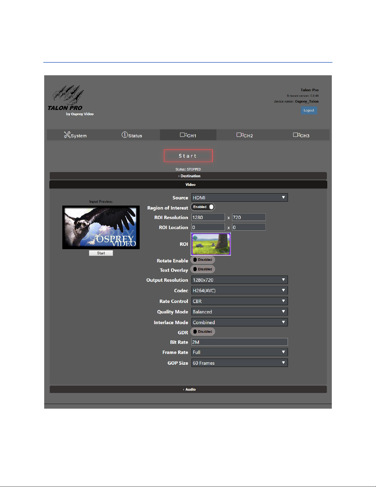
ROI CROPPIN G (ADVANCED)
This feature allows users to select a portion of a larger image for streaming. The output will be the size of the
cropped image rather than the “Output Resolution” selected in the dialog. ROI, Rotation and Text Overlay settings
are only visible if ADVANCED has been selected.
Page 33
Page 33 of 59
ROI RESOLUTION
Select the size to crop. Alternately, you can drag and drop the square in the ROI monitor.
ROI LOCATION
Select the location of the crop. Alternately, you can drag and drop the picture in the ROI Monitor
ROI MONITOR
Displays a frame of the active video for setting ROI Resolution and Location
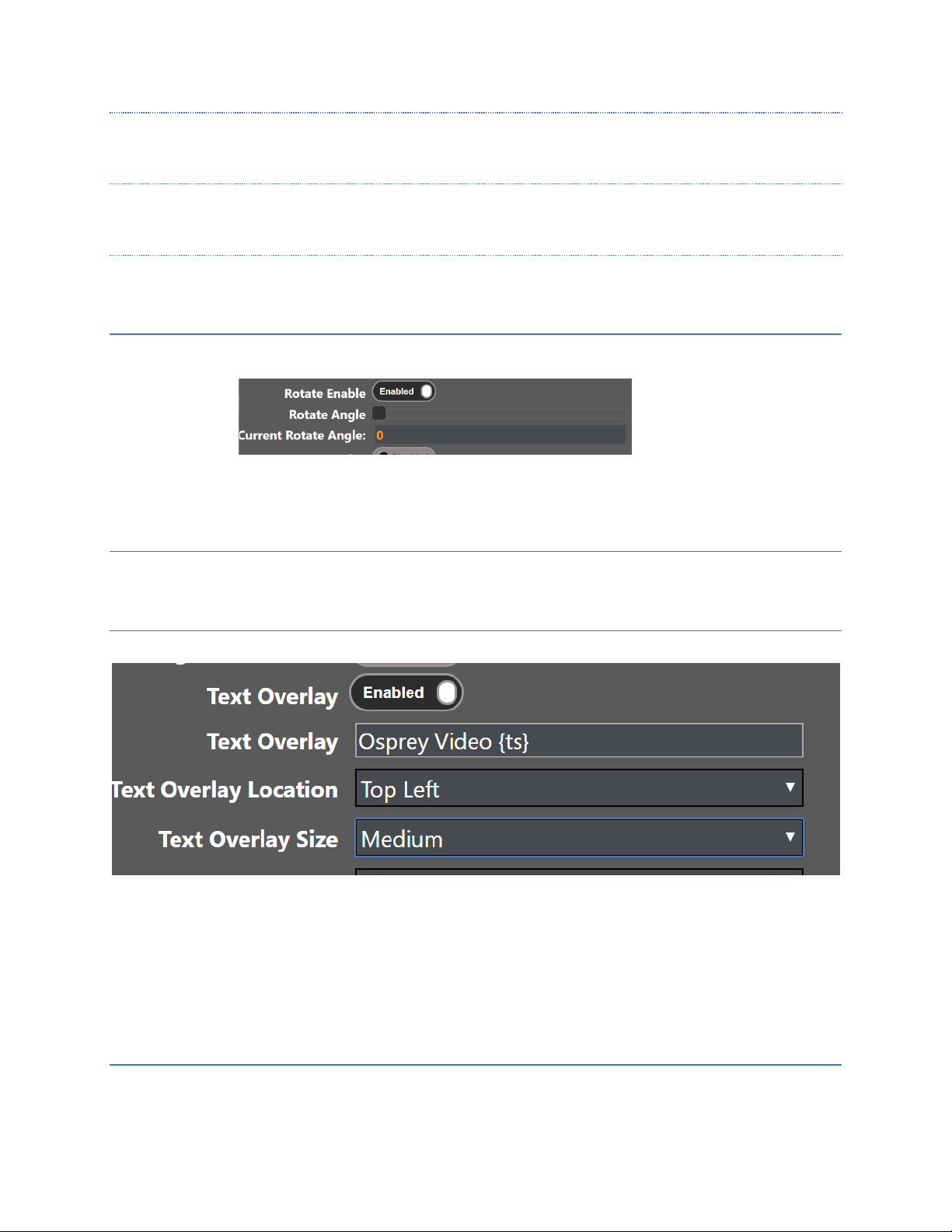
ROTATE ENABLE
Enabling rotation allows compensation for the angle of a stationary camera by changing how it is viewed by the
stream. It is possible to invert the view where necessary by moving the slider. The effect of this change can be
viewed in the stream in real time. It does not show in the live monitors.
CURRENT ROTATE ANGLE
For reference the current setting is shown
TEXT OVERLA Y
When TEXT OVERLAY is enabled, the text in the OVERLAY TEXT box will appear on the streamed video. It can be
used as a watermark, or video identification. Additionally, you may overlay a TIMESTAMP on the video by adding
{ts} in the overlay window. The date and time will be overlayed on the video stream in YYYY-MM-DD HH:MM:SS
format.
Note: To use a different timestamp format add strftime characters in the tag. For example, for timestamp format
of YYYY/MM HH:MM:SS use “{ts%Y/%m %H:%M:%S}”
OVERLAY TEXT
Text Overlay content goes here
Page 34
Page 34 of 59
OVERLAY LO CATION
Select a location for the overlay
OVERLAY TEXT SIZE
Select SMALL, MEDIUM or LARGE for text size.
OUTPUT RESO LUTION
Select a video resolution for the stream from the dropdown. If this resolution is different from the capture
resolution, resizing will occur. Follow Input generates the resolution based on the capture resolution.
CODEC
Selects the codec used for compression of the output video stream.
H265 (HEVC), H264 (AVC), MJPEG
Note: RTMP only supports H264
PROFILE (H264 ONLY) (ADVANCED)
Options as High, Main and Baseline
Page 35

Page 35 of 59
RATE CONTROL (ADVANCED)
Selects the encoder rate control mechanism. VBR (Variable Bitrate) means that the encoding bitrate can fluctuate
within the bitrate statistical period. CBR (Constant Bitrate) means that a stable encoding bitrate is ensured within
the bitrate statistical time.
QUALITY MODE (ADVANCED)
Low Latency, Balanced, High Quality
Low Latency optimizes encoder settings for latency at the expense of quality. High Quality optimizes settings for
quality at the expense of Latency
INTERLACE MODE (ADVANCED)
In the case of interlaced input, this selects how the unit formats the output stream. In Combined mode the top and
bottom fields are combined into a single frame. In separated mode the fields are set separately for an HEVC
stream. Decoders will need to support field separated mode.
Separated mode is not available for H264.
VIDEO BIT RATE
Textbox for entering video bitrate. For example:
1M = 1,000,000 bits per second
1000k = 1,000,000 bits per second
2.5M = Not a Valid Format
Used on RTP, RTSP and RTMP only.
FRAME RATE
Used to encode at less than the input frame rate, (for example, an input frame rate of 30fps with Half selected
would cause an output stream of 15fps). If interlaced input is used, then this is used to reduce the number of fields
being encoded.
GOP SIZE
I-frame frequency. The number of frames in each Group of Pictures (GOP)
10 – 240 Frames, Default 60 Frames
Page 36

Page 36 of 59
AUDIO
AUDIO ENABLE
Enable audio here to encode audio from available sources.
SOURCE
Select from HDMI, HD-SDI1-2, Mic Line-in, Mic, or Auto
Select “MIC Line-In” when using a nonpowered/
non-amplified microphone.
Select “MIC” when using a powered/amplified
microphone. Select “Auto” to follow the video source.
CODEC
Select the codec to be used for the audio encode.
Options are AAC Low Complexity, AAC High Complexity, AACLC Mpeg2, and AAC HE2.
BIT RATE
Target bitrate for audio encode. The bitrate range for AACLC is 12-384 Kbps. 64 Kbps or higher is recommended.
Bitrate range for AACHE and HE V2 is 32-64 Kbps.
SAMPLE RATE
Select the audio sample rate.
48k, 44.1k and 32k are available.
PID
Audio PID for transport streams. Range is 0-8191. Default is 120.
MAX PTS-PCR
Maximum difference between the PTS and PCR in the audio stream. It is generally recommended to leave this
value at 250. Certain decoders may require a value similar to the video delay. If an issue is encountered with a
specific decoder, try setting this value to the same value as the video delay.
Range 0-8191. Default is 250
Page 37
Page 37 of 59
CONFIGURING ENCODER FOR RTMP/RTMPS
Talon PRO supports H.264 streaming to an RTMP streaming server. Osprey Video is a member of the Wowza
Media Systems™ Technology Alliance partner program, and the Wowza Streaming Engine™ is used here
as an example.
Return to the Web UI.
Select CH1, CH2 or CH3.
Ensure that the selected encoder shows a status of “STOPPED”
If necessary, click on the “Stop” button in the “Channel Controls” section of the user interface CH1 tab or
the “Stop All” button in the lower right corner of the screen of any tab.
Select the “Output” ribbon.
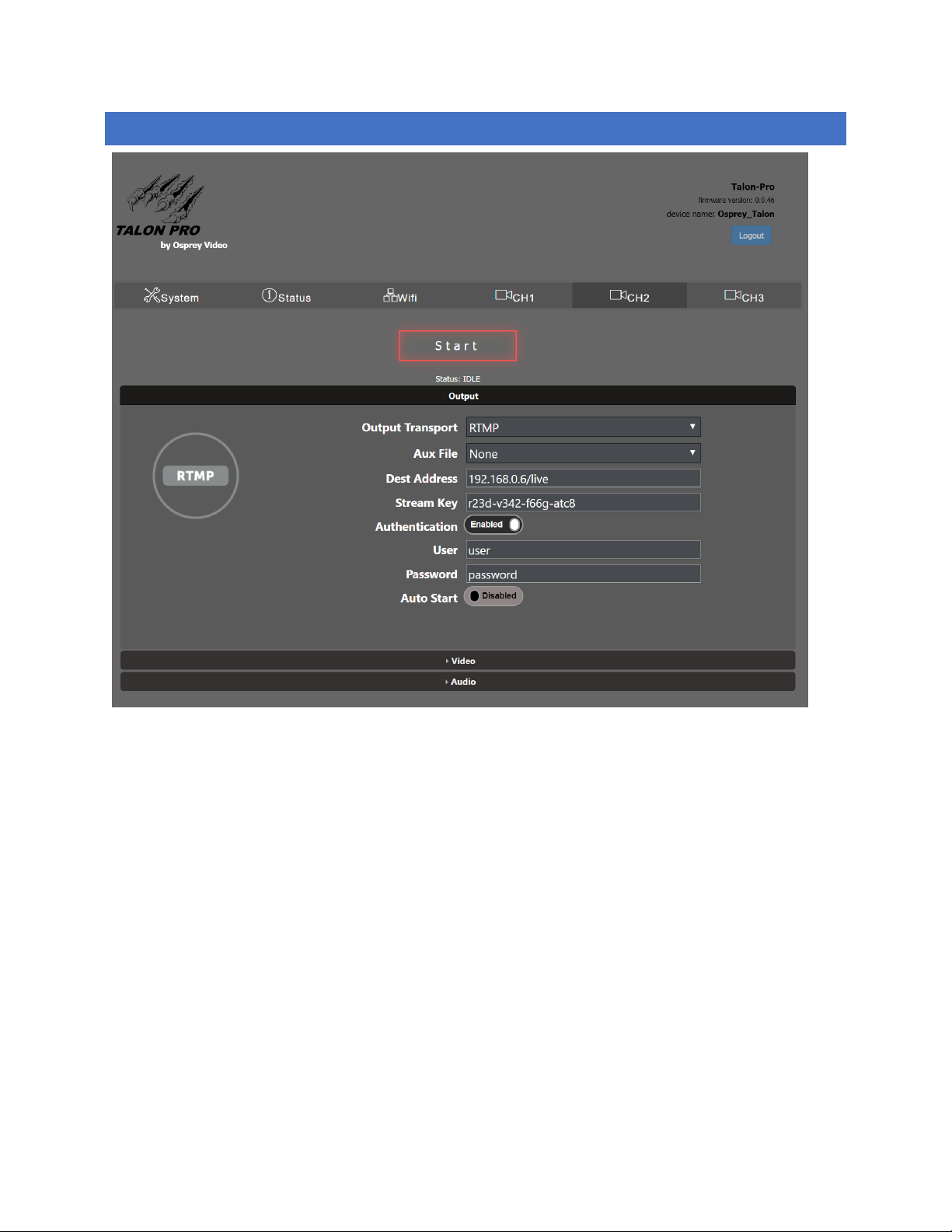
Set “Output Transport” to “RTMP or RTMPS.”
The “Dest Address” textbox should be formatted as “IP_address:port/application” where the IP address
is the address of the PC with the Wowza server installed. Port refers to the port used on this PC. The
Page 38

Page 38 of 59
application will need to match the application used in Wowza and the stream name is of your choosing.
For the pictured example, enter “192.168.0.4:1935/live/”.
The name of the stream, or the Stream Key required by your RTMP server should be entered at “Stream
Key”. For online services such as Youtube Live, place the stream key in the “Stream Key” window.
If your server requires it, set “Authentication” to “Enable” and enter your valid Wowza login credentials.
Continue configuration by selecting the “Video” ribbon.
Select Source, Output Resolution etc from the pull-down menus. Note that H.264 is the only codec available in
RTMP.
Select the “Audio” ribbon
Select from the available options under “Source”
Select which audio pair to use for audio. NOTE: RTMP only accepts one pair at a time. It is not possible to stream
more than one stereo pair per encoding.
Select from the available audio codecs. AAC LC, AAC-HE and AAC HE2 are recommended codecs for AVC and HEVC
encoding.
Select “START”
Page 39
Page 39 of 59
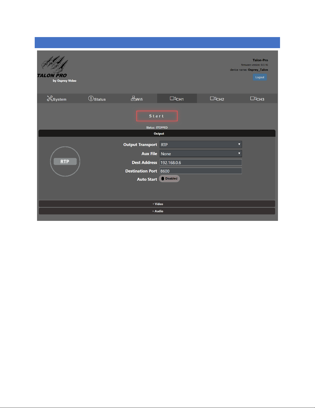
CONFIGURING ENCODER FOR RTP
Return to the Web UI.
Select CH1, CH2 or CH3.
Ensure that the selected encoder shows a status of “STOPPED”
If necessary, click on the “Stop” button
Select the “Output” ribbon.
Set “Output Transport” to “RTP.”
Set “Dest Address” the IP address of the destination of the encoded stream.
Select the “Video” ribbon and select the Output Resolution, Codec and related settings. For RTP you may use
H264(AVC) or H265(HEVC)
Select the “Audio” ribbon and select the Source, Codec and Bitrate for the Audio. NOTE: You may select ONE
stereo pair from the available inputs. (SDI and HDMI expose 4 pairs each)
Select “START”
Page 40

Page 40 of 59
ABOUT SDP FILES
Some RTP/RTSP connections may require a Session Description Protocol (SDP) file that is placed on the media
server to direct users to the stream. Talon does not support creation or automatic injection of SDP files. Should
your media server require such a file, it can be created using notepad. The expected format for delivering video
from Talon is:
v=0
o=- 653 1 IN IN4 TALON_IP
s=Osprey Talon streaming video
t=0 0
m=audio USER_SELECTED_PORT(audio) RTP/AVP 97
a=tool:Talon
a=recvonly
a=type:broadcast
c=IN IP4 DESTINATION_IP
a=rtpmap:97 mpeg4-generic/48000/2
a=fmtp:97 streamtype=5; profile-level-id=14; mode=AAC-hbr; config=0990; sizeLength=13;
indexLength=3; indexDeltaLength=3; constantDuration=1024
m=video USER_SELECTED_PORT(video) RTP/AVP 102
c=IN IP4 DESTINATION_IP
a=rtpmap:102 H264/90000
a=fmtp:102 packetization-mode=1
b=AS:200
Items in BOLD RED type contain user provided information.
Page 41
Page 41 of 59
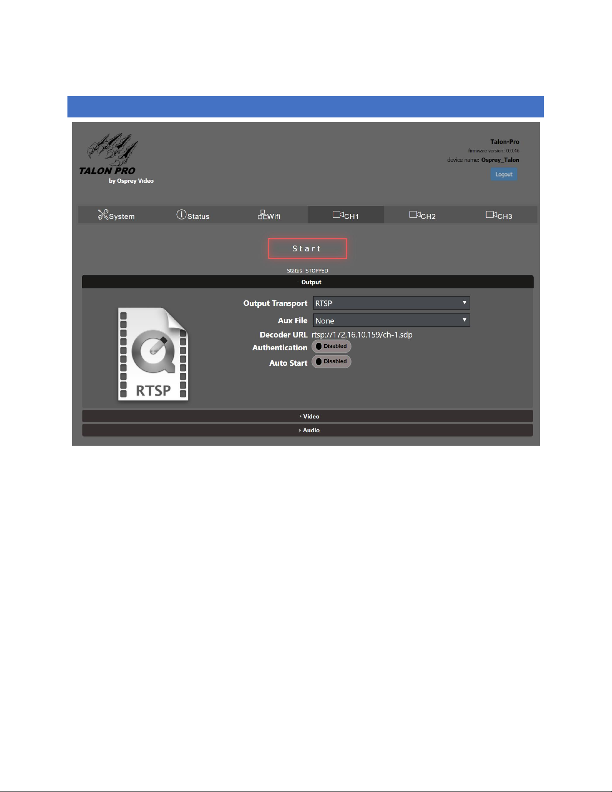
CONFIGURING ENCODER FOR RTSP
Return to the Web UI.
Select CH1, CH2 or CH3.
Ensure that the selected encoder shows a status of “STOPPED”
If necessary, click on the “Stop” button
Select the “Output” ribbon.
Set “Output Transport” to “RTSP.”
The Decoder URL for the RTSP stream will be the IP address of the encoder + /ch-1.sdp
Select the “Video” ribbon and make the appropriate Source, Output Resolution and Codec settings. Note that RTSP
supports both H.265(HEVC) and H.254(AVC).
Select the “Audio” ribbon
Select from the available options under “Source”
Page 42
Page 42 of 59
Select which audio pair to use for audio. NOTE: RTSP only accepts one pair at a time. It is not possible to stream
more than one stereo pair per encoder.
Select from the available audio codecs. AAC LC, AAC-HE and AAC HE2 are recommended codecs for AVC and HEVC
encoding.
Select “START”
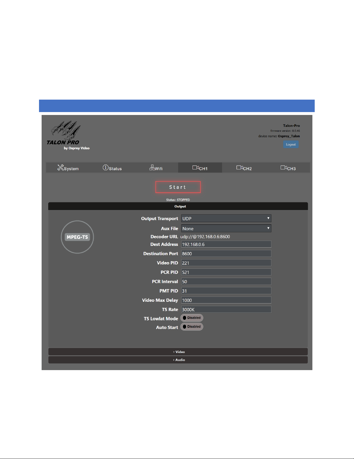
CONFIGURING ENCODER FOR UDP
Return to the Web UI.
Select CH1, CH2 or CH3.
Ensure that the selected encoder shows a status of “STOPPED”
Page 43

Page 43 of 59
If necessary, click on the “Stop” button.
Select the “Output” ribbon.
Set “Output Transport” to “UDP.
You can set the “Dest Address” to:
(a) the IP address of the decoder or decoding PC. (in the pictured example, 192.168.0.6)
(b) or to a multicast address (An example multicast address would be “225.1.2.3”. If you are on a
shared network, check with your Network Administrator.)
Make note of the value of “Dest Port” (This will be “8600” by default).
AUDIO NOTE: When selecting audio channels, HDMI and SDI each support 4 stereo pairs for audio.
When streaming with UDP, users can stream up to four pairs simultaneously.
Page 44
Page 44 of 59
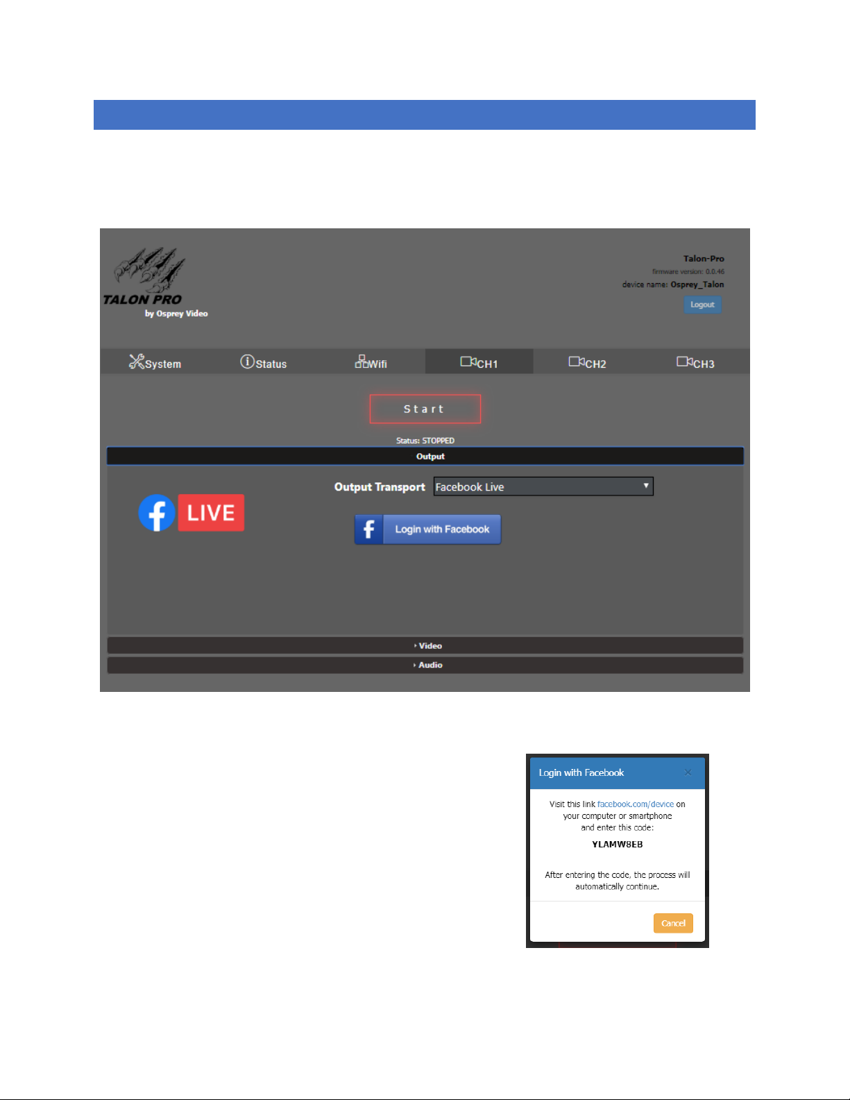
CONFIGURING ENCODER FOR FACEBOOK™ LIVE
If you are going to do 24/7 streaming, or are creating a regular stream every day, Osprey has created an API level
application that works from within Talon. Once Talon has been authorized to stream to your Facebook page or
timeline, it is not necessary to reauthorize the stream. This means that there is no need for the encoder operator
to have full credentials for the Facebook page after the stream is authorized.
To use the Facebook Live API, select it from the Output
Setup pull down menu
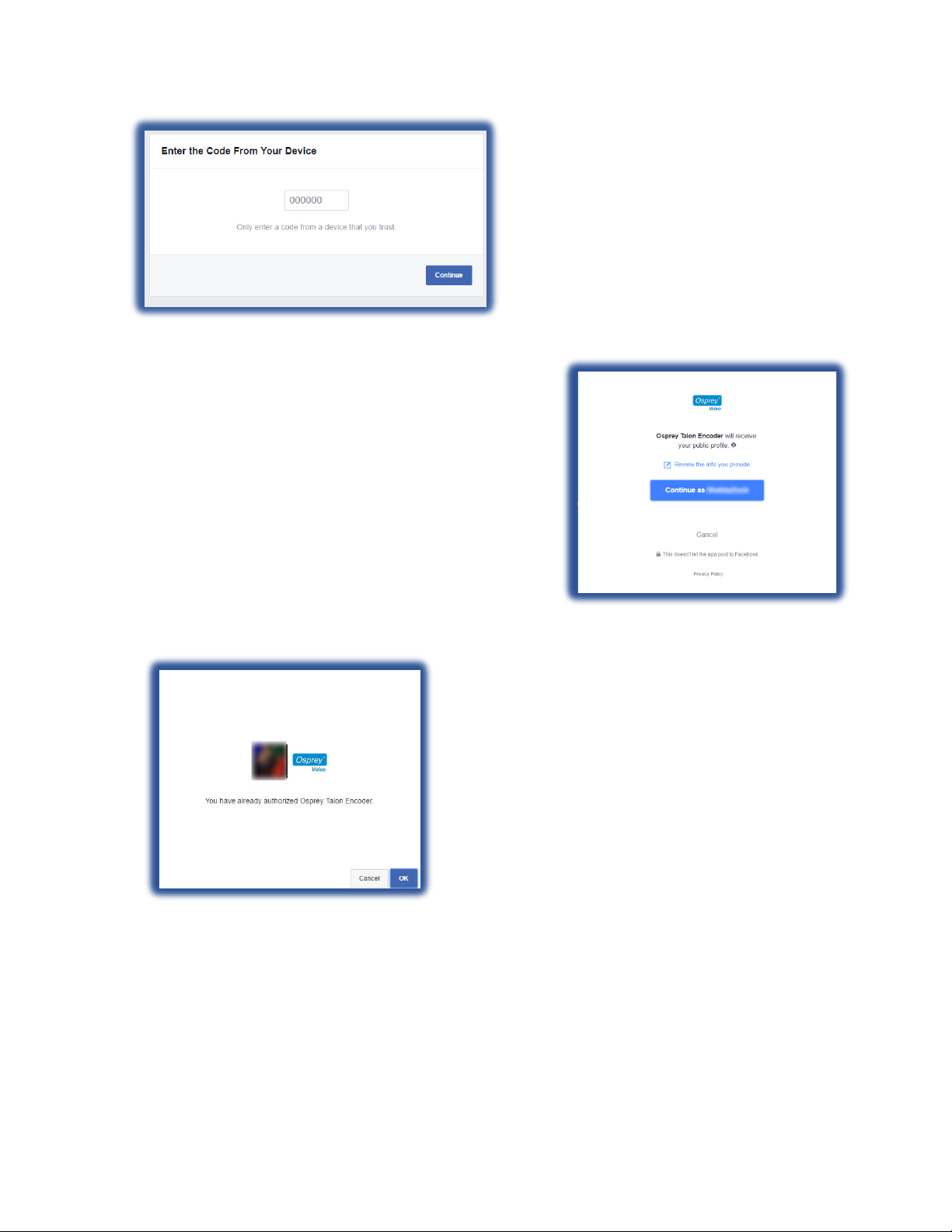
Facebook will respond with a connection code and a link to
their site.
Copy the code and then click on the link. The link will take
you to your Facebook page where you can enter the code
provided. This code authorizes your encoder to send video
to your Facebook page. If your browser isn’t currently
logged in to Facebook, you will need to login now.
Page 45
Page 45 of 59
Press “Continue”
This box tells you that the Osprey Talon
Encoder will receive your public profile.
Press “Continue” to assign posting
permissions to Talon.
If you’ve already granted permissions to
Talon you will receive a message telling
you that the encoder has previously been
authorized.
Page 46
Page 46 of 59
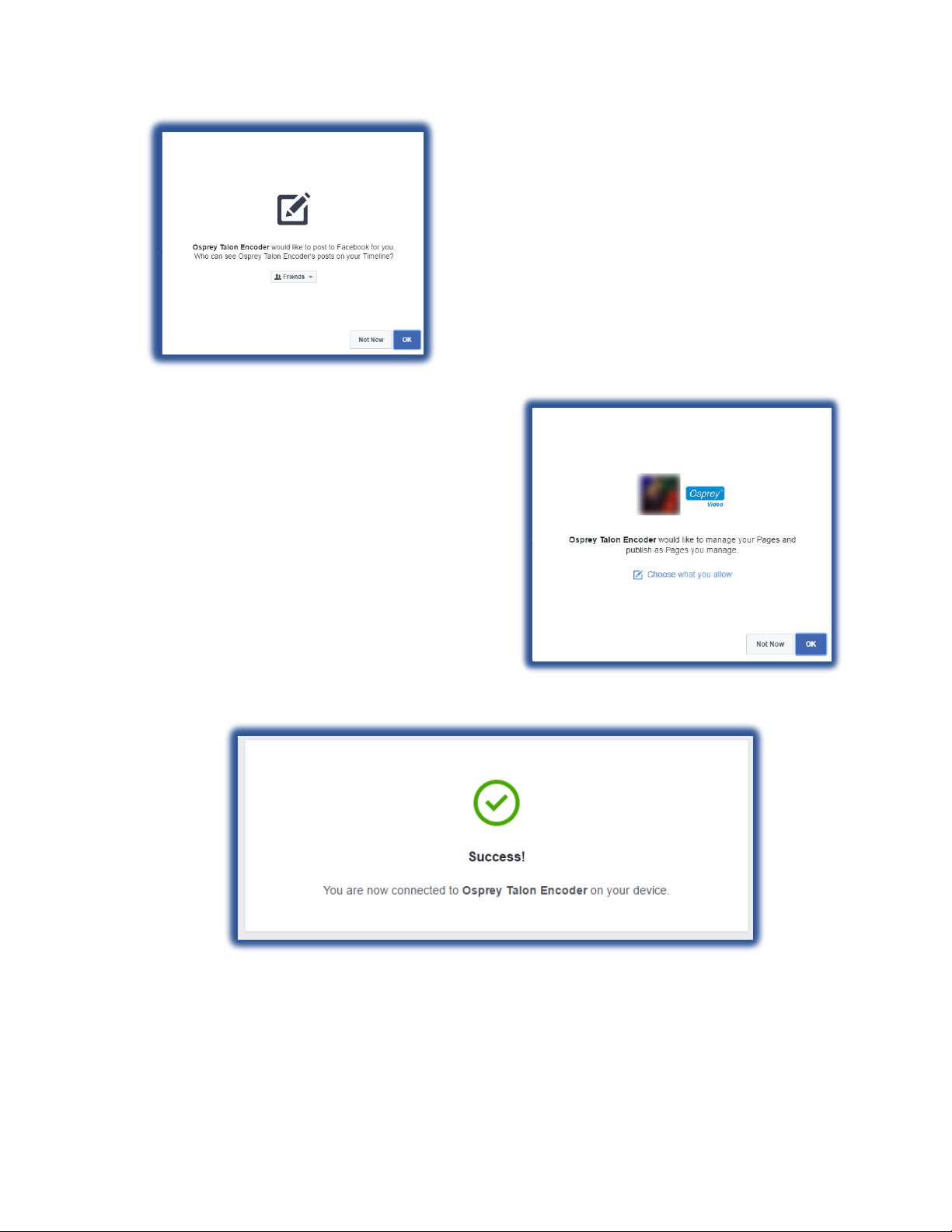
Facebook will need your permission for Talon to
post video to your timeline. You may select what
audience can view the video.
If you have other pages that you manage from this
Facebook account, you can assign permissions to them
here.
You have completed Facebook
configuration. Now go back to Talon to
provision your stream.
Page 47
Page 47 of 59
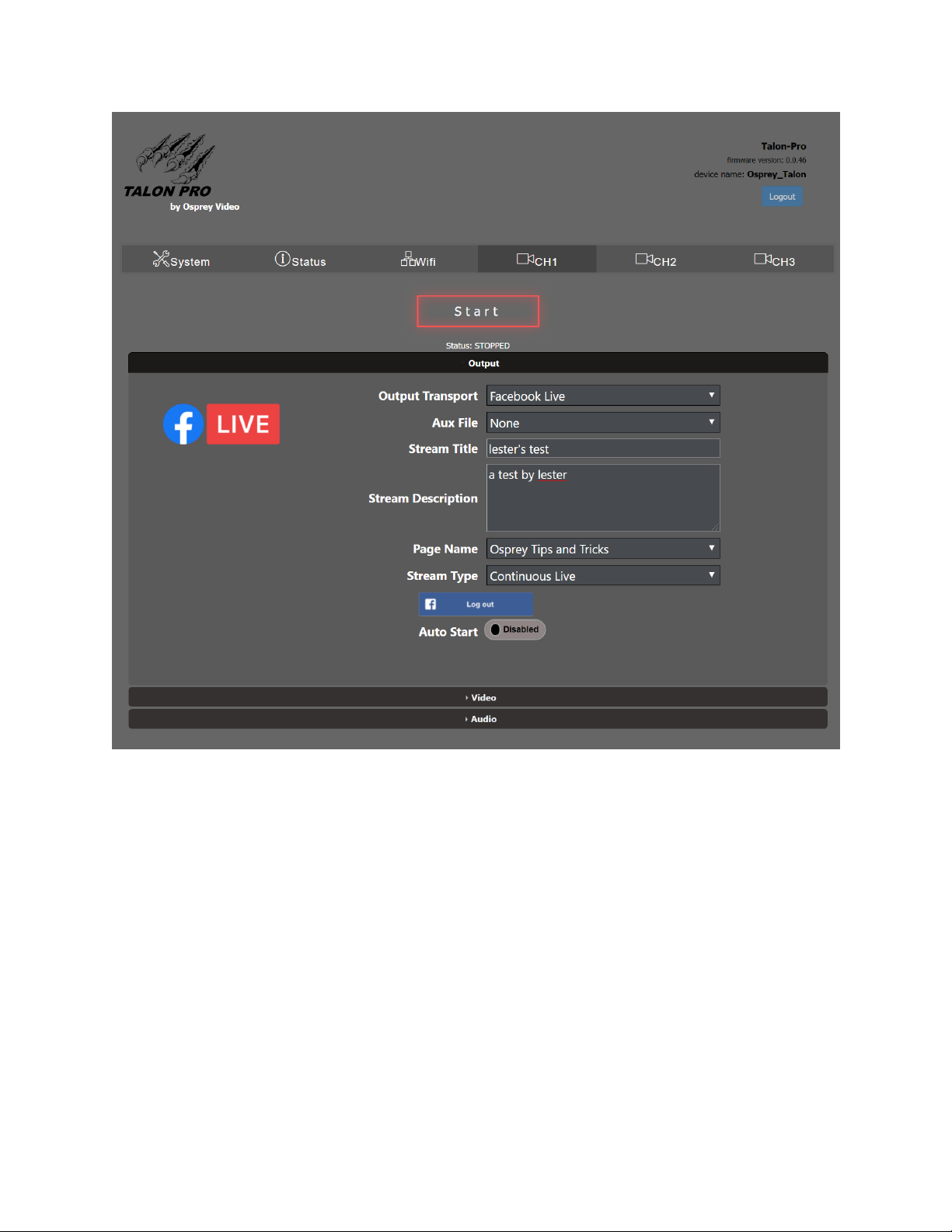
On the Talon PRO output screen enter a “Stream Title” for your Facebook stream, along with a brief description
The name of the page you are posting to will be the “Page Name”. If you manage more than one page with your
Facebook ID you will be able to select which one receives your video.
Last, select the “Stream Type”. Selecting “Continuous Live” will broadcast indefinitely on your page but will never
be archived. Regular streams post for a maximum of four hours. When they stop they are archived to your page.
To begin your stream press “Start”. The stream will end when you stop the encoder. It is not necessary to log out
of Facebook unless you no longer want this encoder to have access to your page.
Unlike streams originating from your regular Facebook page or encoder, it is not necessary to get a new
authorization in order to stream again. Simply select START
Page 48
Page 48 of 59
CONFIGURING ENCODER FOR WOWZA CLOUD
Talon has an API level application integration to allow users to quickly connect with their Wowza Streaming Cloud
® account. Below are the easy steps to connect with Wowza Streaming Cloud.
Create a live stream that uses Osprey as the video source
If you haven't already done so, create a live stream in Wowza Streaming Cloud that uses the Osprey Talon encoder
as the video source.
1. Sign in to Wowza Streaming Cloud.
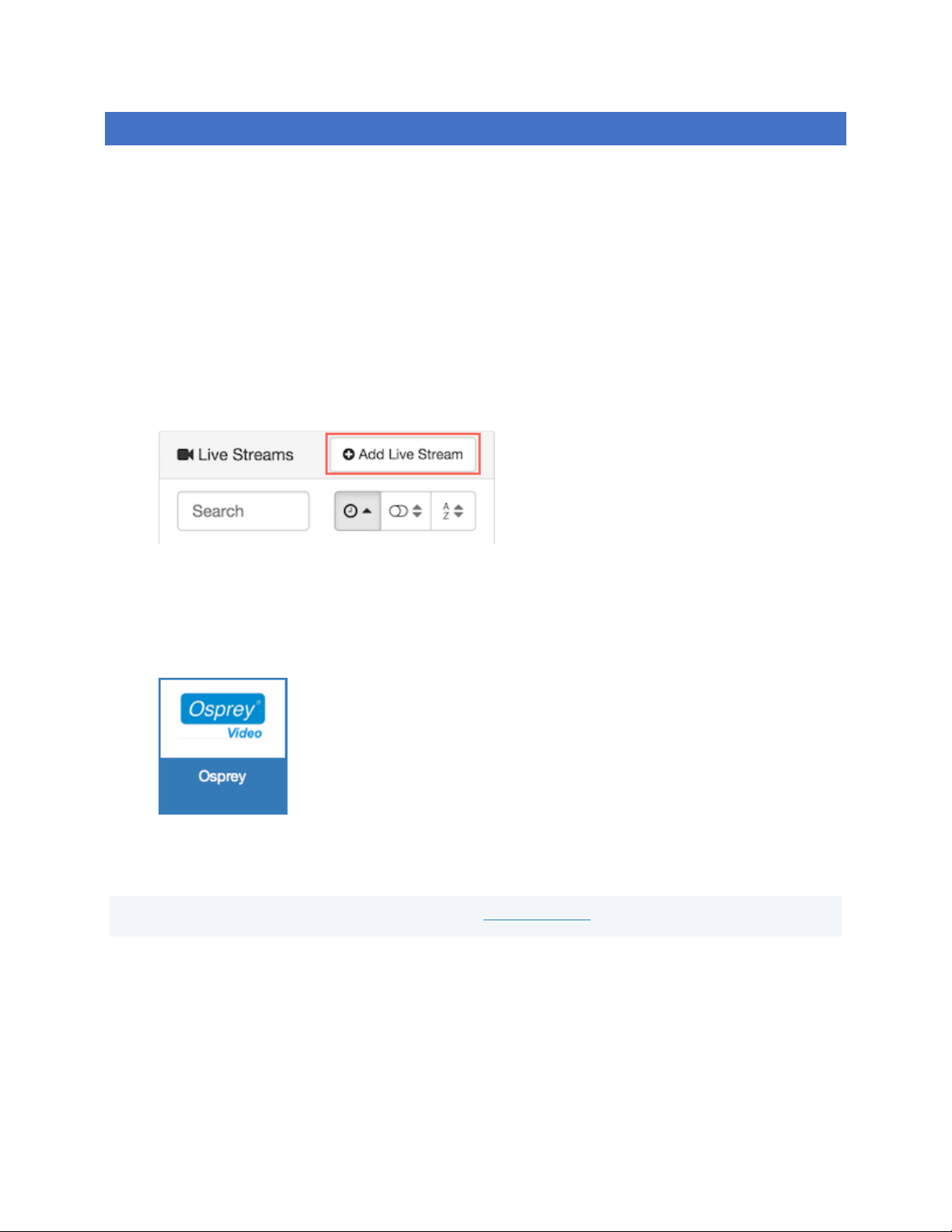
2. Click the Live Streams menu, and then click Add Live Stream.
3. On the Live Stream Setup page, enter a Live Stream Name, choose a Broadcast Location, and then
click Next.
4. On the Video Source and Transcoder Settings page, select Osprey as the encoder you want to use
to connect to Wowza Streaming Cloud.
5. Specify other video source settings, click Next, and complete the steps to finish creating the live
stream.
Note: For more information about live stream settings, see Add a live stream.
Wowza Streaming Cloud creates the live stream and displays the Overview tab of the live stream detail page.
Connect the Osprey Talon to Wowza Streaming Cloud
After you've added a live stream in Wowza Streaming Cloud, configure the Osprey Talon to connect to it. You can
configure the Talon in either of two ways: by using the Wowza Streaming Cloud connection code, or by using the
XML connection settings file that Wowza Streaming Cloud generated for the live stream.
Page 49
Page 49 of 59
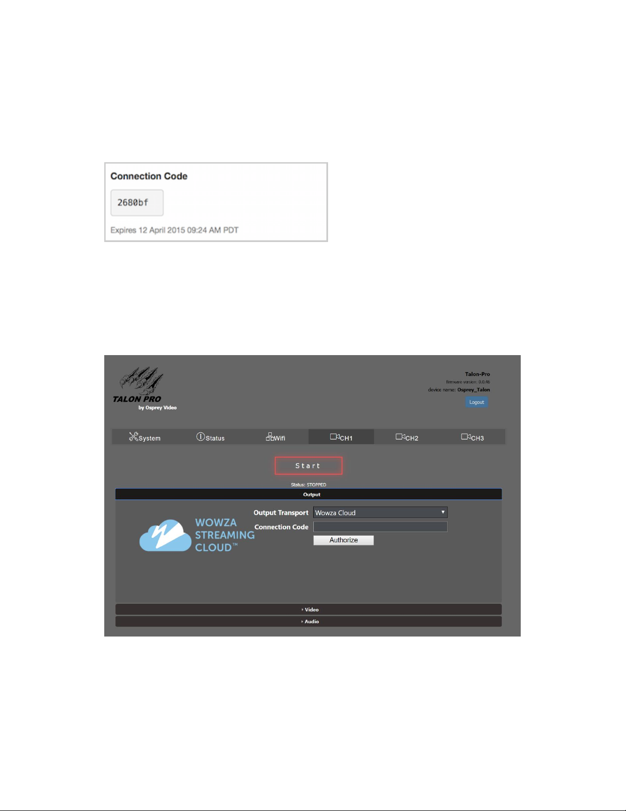
Connect using the Connection Code
1. In the Live Streams panel of the Live Streams page of Wowza Streaming Cloud, select the live
stream that uses Osprey as its video source.
2. On the Overview tab of the live stream detail page, make note of the six-digit Connection Code.
3. Sign in to the Osprey Talon web-based admin interface.
4. Click the CH1 tab or click the plus sign to create a new stream.
5. Under Output, for Output Transport, choose Wowza Cloud.
6. Enter the Connection Code from the Overview tab of your live stream detail page.
7. Click Authorize.
8. Configure any other required settings for your broadcast. See the Encoder Setup section for
information on how to configure a stream.
Page 50
Page 50 of 59
Configure any other required settings for your broadcast. See the “Encoder Setup” portion of this
guide for information on how to configure a stream.
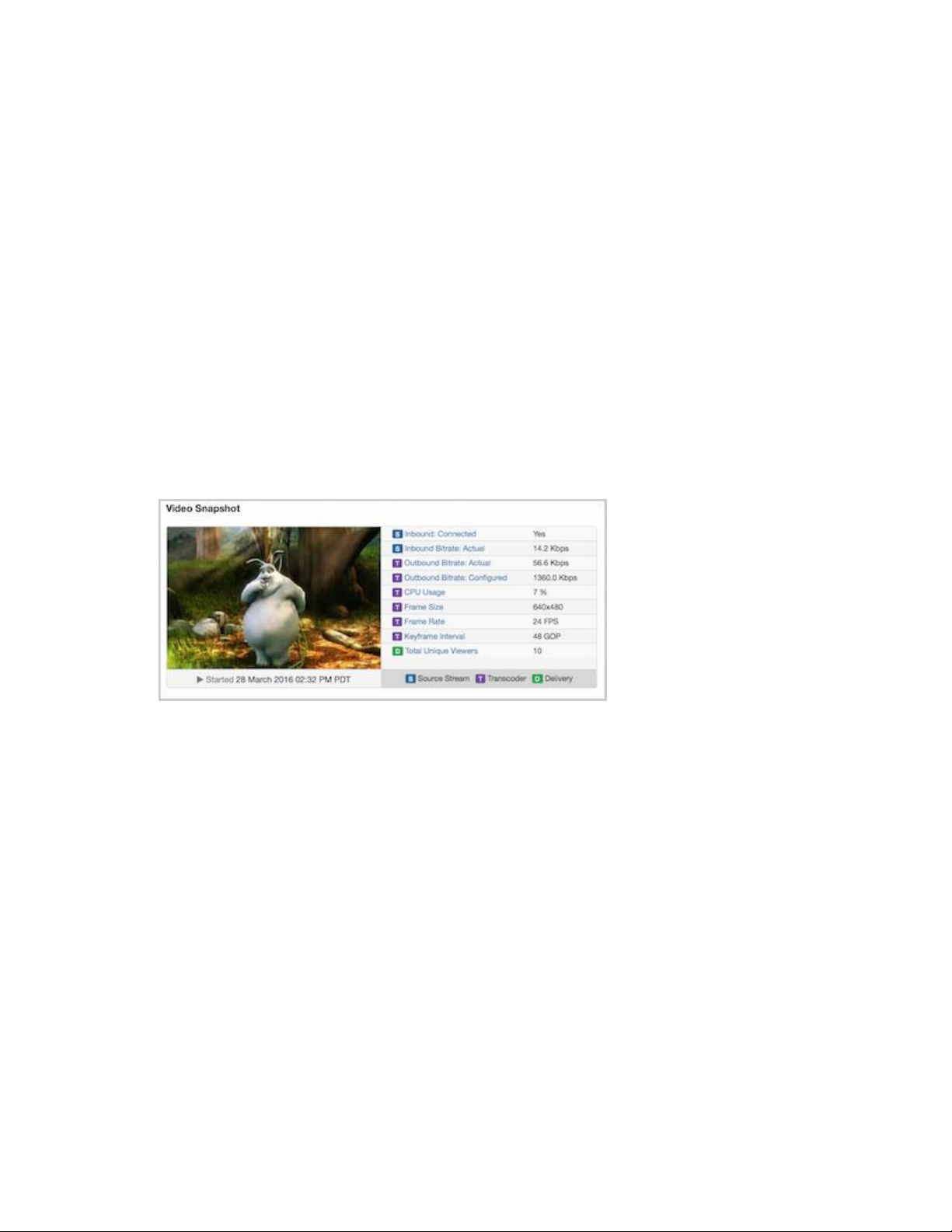
Test the connection
1. In the Wowza Streaming Cloud web manager, select the live stream that uses the Osprey Talon as
its video source.
2. Click Start Live Stream at the top of the live stream detail page.
3. Click Start to confirm that you want to start the stream.
Wowza Streaming Cloud opens the stream and connects with the Osprey encoder.
4. In the Osprey Talon admin interface, start your video source.
5. In the Wowza Streaming Cloud web manager, confirm that the stream is working by looking at
the Video Snapshot in the Overview tab of the live stream detail page.
The video snapshot displays a frame from the live stream every 5 seconds. The started date and
time appear under the snapshot. Source stream, transcoder, and delivery metrics begin to update.
6. Click Stop Live Stream at the top of the live stream detail page to end your test stream, and then
stop the stream in the Osprey encoder.
For more information regarding Wowza Streaming Cloud check out
https://www.wowza.com/forums/content.php?810-How-to-connect-an-Osprey-Talon-encoder-to-WowzaStreaming-Cloud.
Page 51
Page 51 of 59
CONFIGURING ENCODER FOR ZIXI™ BROADCASTER
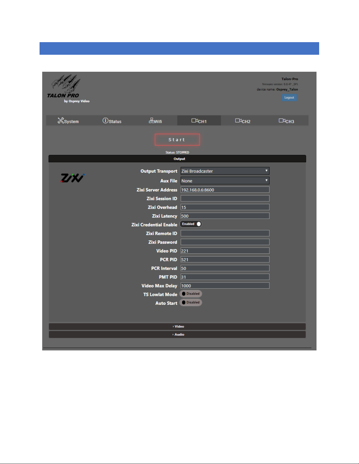
Talon PRO can act as a Zixi Feeder. If you have an existing Zixi account simply select “ZIXI” from the Output Setup dialog.
Insert your Zixi Destination Address and Session ID (Channel Name).
When Zixi Credential is enabled, users can enter their Zixi Password. Authentication uses a combination of the Session ID and
Password. If assigned on the Zixi Broadcaster, the Zixi Remote ID grants access priority for that channel. Any other connected
stream will be removed and replaced by the holder of the Remote ID. The rest of the Zixi settings are set at their default. If you
need to adjust these settings, consult your Zixi Broadcaster instructions.
Page 52
Page 52 of 59
CONFIGURING ENCODER FOR STREAMSPOT
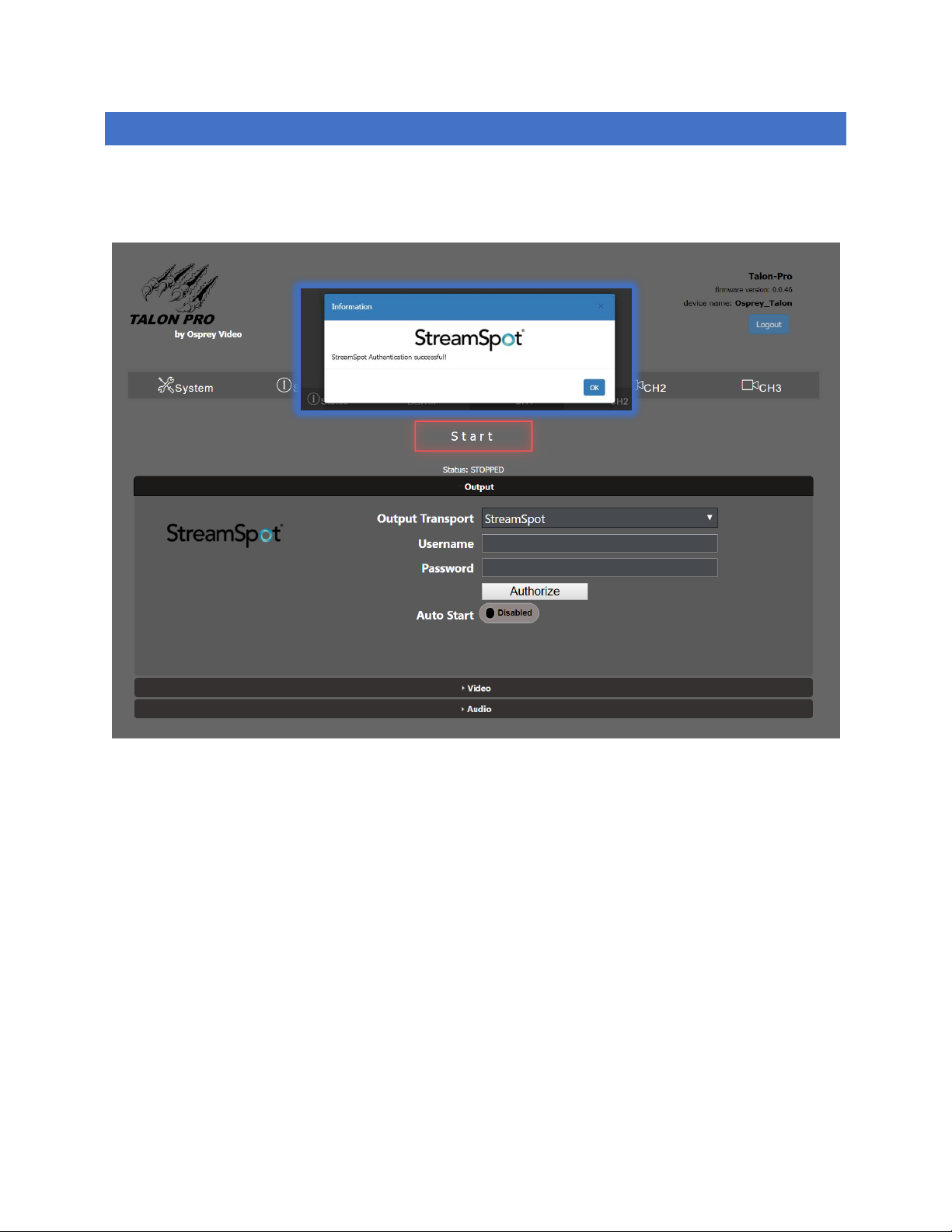
Talon PRO has API support for StreamSpot. To use your pre-existing StreamSpot account, select StreamSpot from the “Output
Format” menu and enter your Username and Password and click “Authorize”.
When authorization is successful, StreamSpot will respond
with a completion dialog. Close the dialog and and start your
encoder. The encoder will remain authorized until you select
“Logout”.
If you have access to additional sub accounts from your login
they will be available in the pull-down and can be selected
befor you start the stream.
Page 53
Page 53 of 59
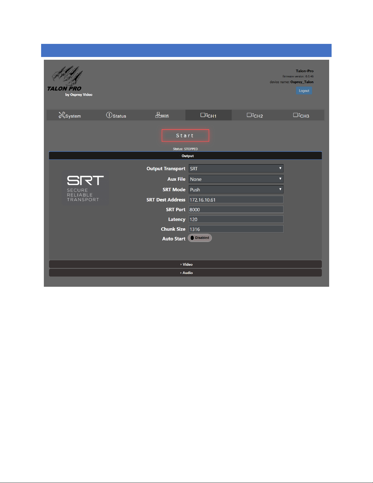
CONFIGURING ENCODER FOR SRT
To PUSH a stream with SRT, select from the Output Transport and enter the SRT Destination address and port. The
remainder of the settings are set to SRT defaults.
Page 54
Page 54 of 59
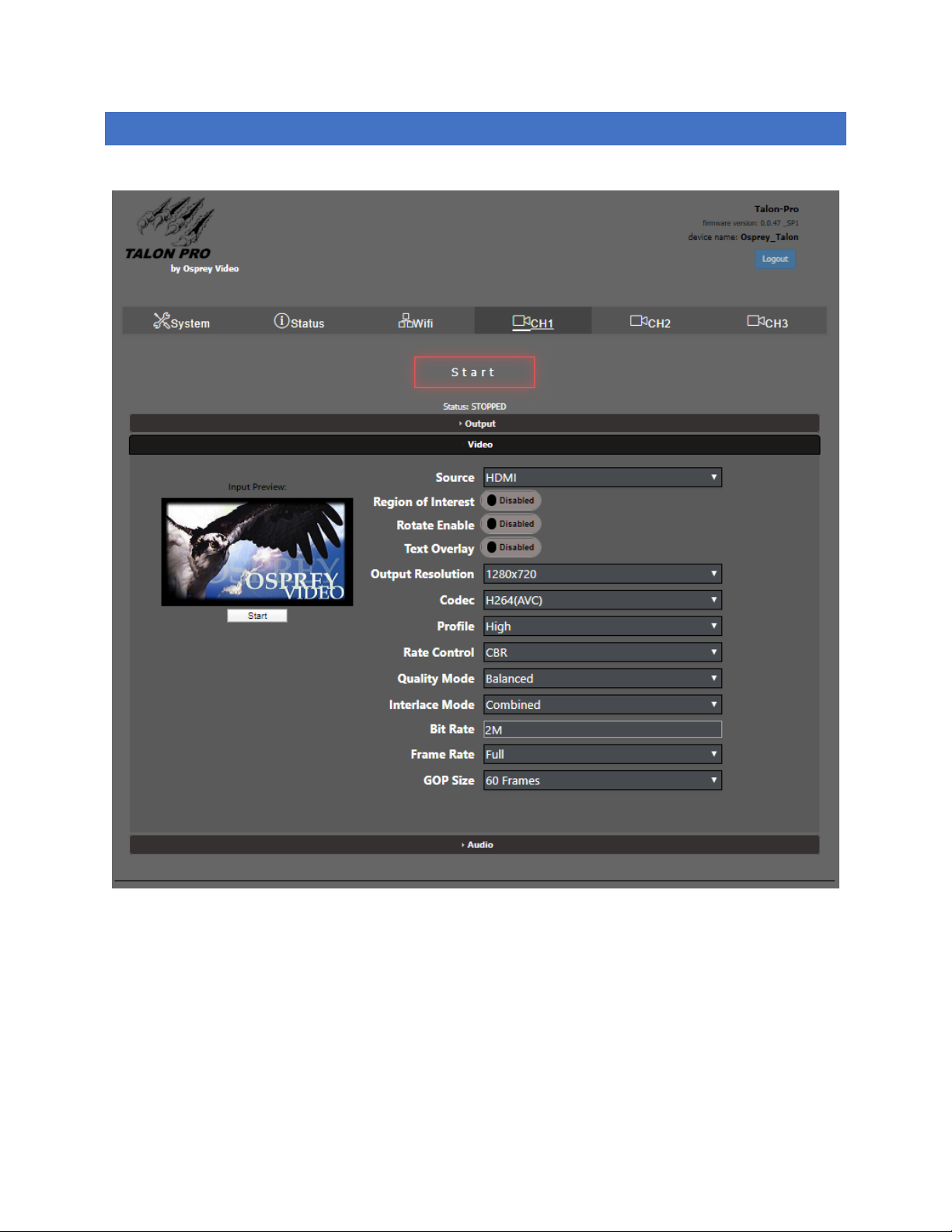
CONFIGURING H.264(AVC) ENCODING
When H.264 codec is selected, options specific to that codec become available in the “Video” ribbon.
Profile: Baseline, Main or High
The H.264 profile of the bitstream. Generally High is used for 2160p or greater, Main for D1, and Baseline for less
than D1. This option will not be available when H.265 Video Codec is selected.
Rate Control: VBR or CBR
Page 55

Page 55 of 59
Selects the encoder rate control mechanism. VBR (Variable Bitrate) means that the encoding bitrate can fluctuate
within the bitrate statistical period. CBR (Constant Bitrate) means that a stable encoding bitrate is ensured within
the bitrate statistical time.
Quality Mode: Low Latency, Balance, High Quality
Low Latency optimizes the encoder settings for latency at the expense of quality and High Quality optimizes the
encoder settings for quality at the expense of latency.
Page 56
Page 56 of 59
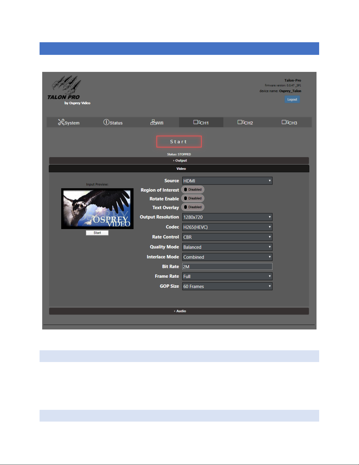
CONFIGURING H.265 (HEVC) ENCODING.
When H.264 codec is selected, options specific to that codec become available in the “Video” ribbon.
RATE CONTROL: VBR OR CBR
Selects the encoder rate control mechanism. VBR (Variable Bitrate) means that the encoding bitrate can fluctuate
within the bitrate statistical period. CBR (Constant Bitrate) means that a stable encoding bitrate is ensured within
the bitrate statistical time.
QUALITY MODE: LOW LATENCY, BALANCE, HIGH QUALITY
Page 57

Page 57 of 59
Low Latency optimizes the encoder settings for latency at the expense of quality and High Quality optimizes the
encoder settings for quality at the expense of latency.
INTERLACE M ODE: COMBINED, SE PARATE D
In the case of interlaced inputs this selects how the unit formats the output stream. In Combined mode the top
and bottom fields are combined into a single frame. In separated mode the fields are set separately for an HEVC
stream. The decoder will need to support field separated mode.
Page 58
Page 58 of 59
Video Inputs:
• 2 x 3G/HD/SD-SDI with Loopouts
• 1 x HDMI 1.4 UHD
Audio Inputs:
• 2 x Embedded SDI (4 Stereo Pairs each)
• 1 x Embedded HDMI (4 Stereo Pairs)
• 1 x Analog unbalanced stereo
Video Input Resolution:
• Up to 3840x2160 (UHD) 30fps on HDMI
• Up to 1920x1080 60fps on SDI
HDMI Output:
• Selectable preview of any input
Streaming Transports:
• RTMP, UDP, RTP, RTSP, SRT™, Zixi™,
• Saving to MP4 and TS file
• CDN integrations
Video Processing:
• Upscale/Downscale, Frame rate Conversion,
Deinterlacing, Text Overlay, Region of
Interest, Image Rotation
Video Compression:
• H.264 (AVC), H.265 (HEVC), MJPEG
Encoding Controls
• Maximum 100Mbit/s Aggregate Output Bitrate
• 40Mbit/s per channel instance
• Frame rate Full, Half, Quarter and Sixth
• Low Latency option <55ms
Closed Captions
• Re-embeds existing CEA608/708 captions
Audio Compression:
• AAC-LC, AAC-HE, AAC-HEv2
Audio Sample Rate
• 32kHz, 44.1kHz, 48kHz
• Audio Bitrate 12Kbps to 384Kbps
Storage
• Network Drive
• USB drive
• Micro SD
Power
• 9.0 ~ 15.4VDC | 7W
• Redundant power connections
Specifications:
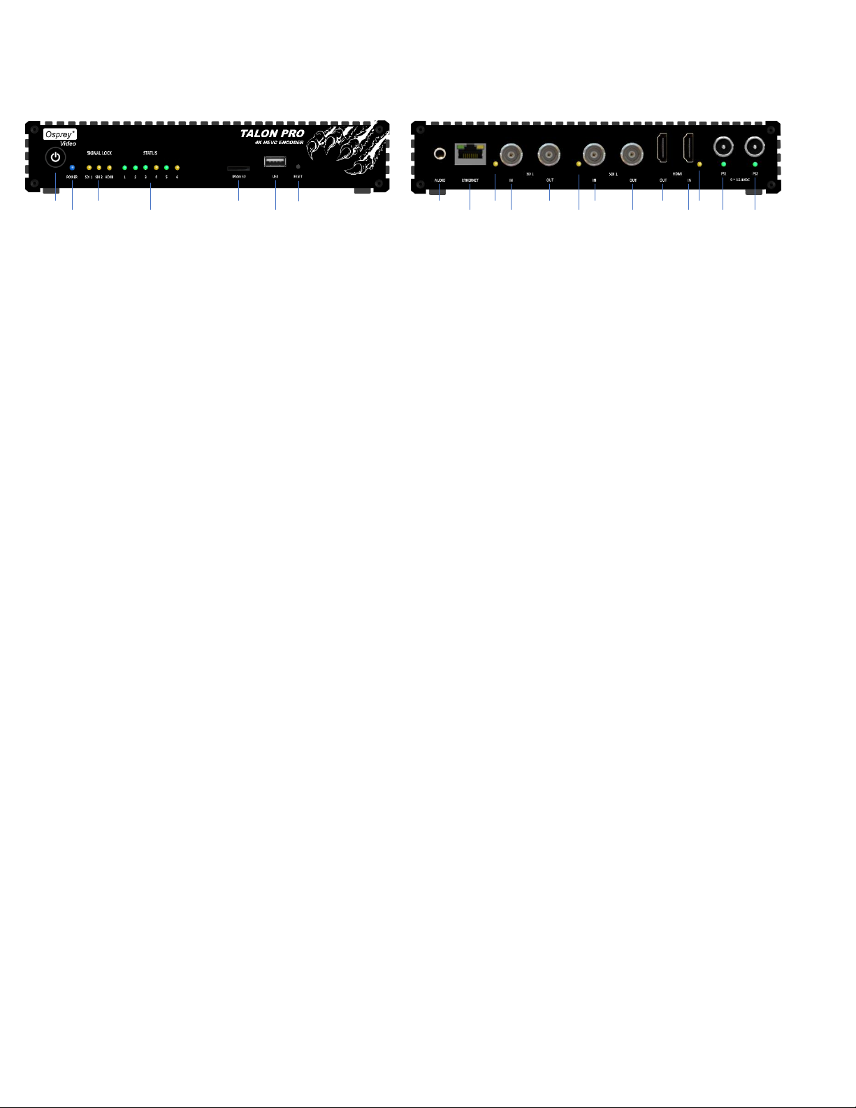
On/Off Switch Video Input Lock LED’s Micro SD for Video Storage Syste m Reset
Power and Boot Status LED Customizable Status LED’s USB2.0 for Video Storage
Unbalanced Stereo Input SDI2 Input Lock SDI 2 Loopout SDI 1 Input HDMI Output Input Lock
Gigabit Ethernet SDI 2 Input S DI1 Input Lock SDI 1 Loopout HDMI In put Redundant Power Inputs
Page 59
Page 59 of 59
www.ospreyvideo.com
© 2019 Osprey Video. All rights reserved.
Osprey® is the registered trademark of Osprey Video. Microsoft®, Windows® is a registered trademark of Microsoft Corporation. Any other product names, trademarks, trade names, service
marks, or service names owned or registered by any other company and mentioned herein are the property of their respective companies.
No part of this specification may be reproduced, transcribed, transmitted or stored in a retrieval system in any part or by any means without the express written consent of Osprey Video.
Osprey Video reserves the right to change any products herein at any time and without notice. Osprey Video makes no representations or warranties regarding the content of this document,
and assumes no responsibility for any errors contained herein.
 Loading...