

Page 1
API Guide MSS-8 and MVS-16
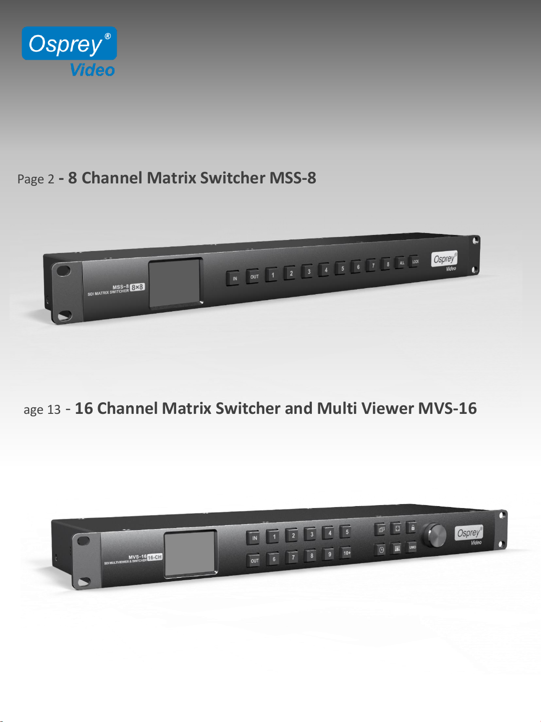
Page 2 - 8 Channel Matrix Switcher MSS-8
Page 13 - 16 Channel Matrix Switcher and Multi Viewer MVS-16
www.ospreyvideo.com 1
Page 2

RACKMOUNT 8x8 MATRIX SWITCHER
MSS-8
API Instructions for RS232
RS232 Connection:
Port Settings: Bps 9600, Data bits 8, Parity None, Stop Bits 1, Flow Control None
Communication Protocol:
The protocol has 3 formats as below. It is sent as ASCII Code and not processed back (no
feedback results)
[x]v[y]. Connect Input “x” with Output “y”
[x]v[y],[z]. Connect Input “x” with Output “y” and “z”
[x]All. Connect Input “x” with all Outputs
Examples:
1v2. Input 1 to Output 2
1v2,3,4,5. Input 1 to Outputs 2,3,4,5
5All. Input 5 to All Outputs
- All instructions must end with a “.”
- With the “v” format multiple outputs can be assigned to a single input
- “All” always represents Output Channels
- Only one Input can be routed with each command line
www.ospreyvideo.com 2
Page 3

RACKMOUNT 8x8 MATRIX SWITCHER
MSS-8
Configuration and Control API Guide for LAN
Description:
This document describes the Osprey Matrix Switch Configuration and Control API
(OMSCC API). The API uses HTTP UDP packet transmissions utilizing both broadcast
and unicast addresses.
All Osprey Matrix Switchers are shipped with the OMSCC API pre-installed. This API
can be used in C++, C#, Java, IOS, etc. There is a full C# example application that can
be complied in Microsoft Visual Studio at the end of this User Guide.
Locating a Switcher on the Network
Method: UDP Broadcast
Packet Format: a56c140081ff01000000000000000000ffa503
Destination Address: Broadcast 255.255.255.255
Destination Port: 7000
Response Payload:
aA56c230082ff01000000000000000000ff004d5353303831312d102d43043155a906ae
(hex)
The above red marked 82 indicate the device type 0x82, means matrix switcher.
The above red marked 00 indicate data return succeed.
The above green marked 4D 53 53 30 38 31 31 2D 10 2D 43 04 31 55 indicates that this
is the Osprey 8x8 Matrix Switcher. Different matrix switcher will return different codes.
www.ospreyvideo.com 3
Page 4

RACKMOUNT 8x8 MATRIX SWITCHER
MSS-8
Configuring Output Ports
Description:
The following commands configure the output ports to output based on the configured
input port.
Method: UDP Unicast
Destination Address: IP address of the matrix switcher
Destination Port: 7000
Commands Table: All commands must be sent as ASCII code to the IP address of the
matrix switch on port 7000.
[x]v[y]. Connect Input “x” with Output “y”
[x]v[y],[z]. Connect Input “x” with Output “y” and “z”
[x]All. Connect Input “x” with all Outputs
Examples:
1v2. Input 1 to Output 2
1v2,3,4,5. Input 1 to Outputs 2,3,4,5
5All. Input 5 to All Outputs
All#. All channels correspond one by one
- All instructions must end with a “.”
- With the “v” format multiple outputs can be assigned to a single input
- “All” always represents Output Channels
- Only one Input can be routed with each command line
- Response Payload – none
www.ospreyvideo.com 4
Page 5
RACKMOUNT 8x8 MATRIX SWITCHER
MSS-8
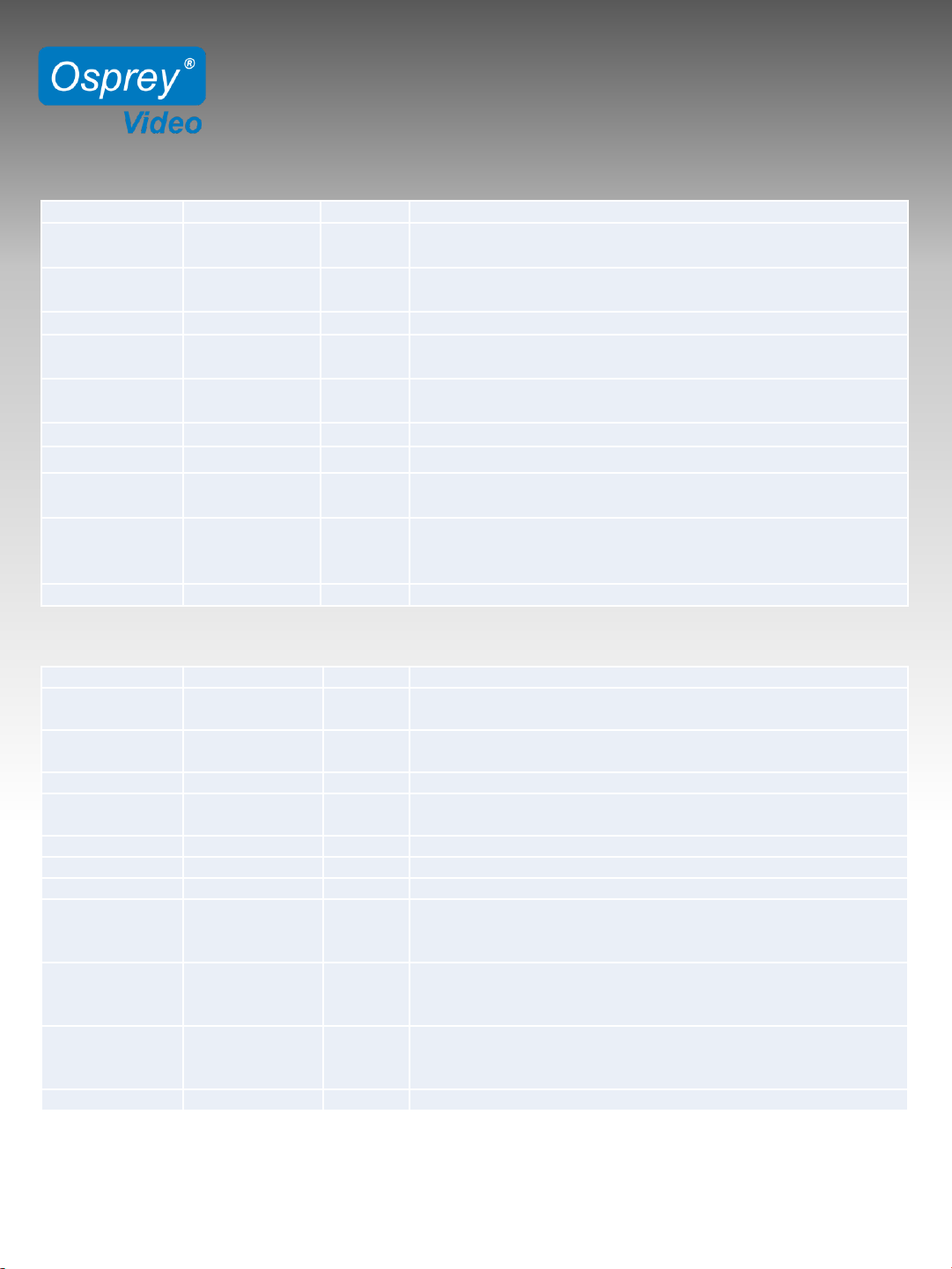
Broadcast from PC to MSS-8
Response from MSS-8 to PC
www.ospreyvideo.com 5
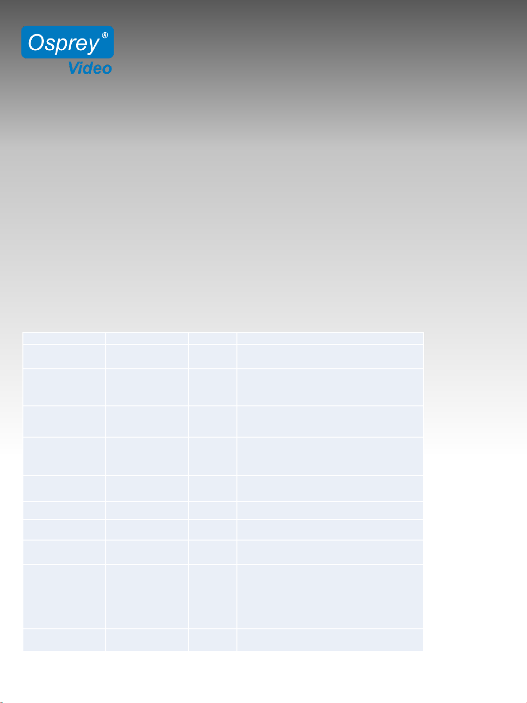
Data Packet Value Byte Description
Packet Header 0xA5
0x6C
2 The beginning of data packet
Data Length 0x0000~0x0420 2 The length of the entire data packet from packet header to end
(including header and end). The lower byte stays head.
Device Type 0x00~0xFF 1 Definition of device type, OXFF means broadcast.
Device ID 0x00~0xFF 1 A distinguishing of the device when there are several devices in a
same LAN at same time. OXFF means broadcast.
Interface Type 0x00~0xFF 1
0x00:UART(serial port)
0x01: LAN
Reserve 0x00 9 For reserve. This device is not reserved.
Command 0x00~0xFF 1 Command for each function.
Packet Data ……….. Variable
length
<= 1024
Checksum 0x0000~0xFFFF 2 The algebraic sum of all bytes from packet header to checksum
(including the packet header but excluding the checksum). Take 2
bytes, other parts omitted. The lower byte stays ahead.
Packet End 0xAE 1 The end of the packet.
Data Packet Value Byte Description
Packet Header 0xA5
0x6C
2 The beginning of data packet.
Data Length 0x0000~
0xFFFF
2 The length of the entire data packet from packet header to end
(including the packet header and end). The lower byte stays ahead.
Device Type 0x00~0xFF 1 Definition of device type, OXFF means broadcast.
Device ID 0x00~0xFF 1 A distinguishing of the device when there are several devices in a
same LAN at same time. OXFF means broadcast.
Interface Type 0x00~0xFF 1
0x00: UART(serial port); 0x01: LAN
Reserve 0x00 9 Reserve. This device is not reserved.
Command 0x00~0xFF 1 Command for each function.
Response Status 0x00 ~ 0xFF 1 0x00: Succeed;
0x01: Error;
Other data undefined.
Response
Content
Variable
length
Reserve. The length of response content is variable when backward
reading command, and it is consistent with the format of "packet
data".
Checksum 0x0000~0xFFFF 2 The algebraic sum of all bytes from packet header to checksum
(including the packet header but excluding the checksum). Take 2
bytes, other parts omitted. The lower byte stays ahead.
Packet End 0xAE 1 The end of the packet.
Page 6
RACKMOUNT 8x8 MATRIX SWITCHER
MSS-8
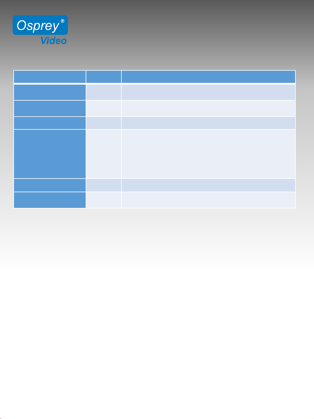
Command List
www.ospreyvideo.com 6
Function Command Description
Read Status of Switcher 0x53 Read the current status of switcher, including IP status, input and
output information, and device name.
Read Status of LCD 0x50 Read the current status of LCD information, including LCD backlight
time and LCD brightness. (Device type: 0x03)
Setting Device Name 0x0f Send the device name (max 16 character) by Unicode
Setting LCD Backlight Time 0x51 0: 15s Dim
1: 60s Dim
2: 15s Off
3: 60s Off
4: Always On
(Device type: 0x03)
Setting LCD Brightness 0x52 Set the LCD brightness between 10-100. (Device type: 0x03)
Setting IP between Static
and Dynamic
0x05 The 13th byte of the data bit
0x01: Dynamic IP; 0x00: Static IP
Page 7
RACKMOUNT 8x8 MATRIX SWITCHER
MSS-8
www.ospreyvideo.com 7
Examples
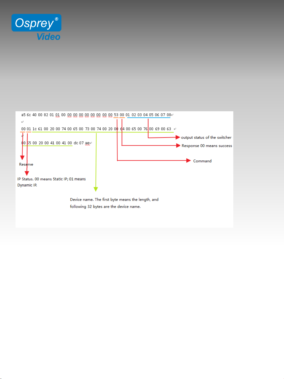
Read the current status of switcher
Broadcast
a5 6c 14 00 82 01 01 00 00 00 00 00 00 00 00 00 53 fc 01 ae
Response Payload:
Read Status of LCD
Broadcast
a5 6c 14 00 03 01 01 00 00 00 00 00 00 00 00 00 50 7a 01 ae
Response Payload:
a5 6c 17 00 03 01 02 00 00 00 00 00 00 00 00 00 50 00 00 2b a9 01 ae
00 indicates the current LCD Backlight Time is 15s Dim.
2b indicates the current LCD Brightness is 43
Setting the device name to “this is a matrix”
Broadcast
a5 6c 34 00 82 ff 01 00 00 00 00 00 00 00 00 00 0f 74 00 68 00 69 00 73 00 20 00 69 00 73 00 20
00 61 00 20 00 6d 00 61 00 74 00 72 00 69 00 78 00 c0 08 ae
Response Payload:
a5 6c 15 00 82 ff 01 00 00 00 00 00 00 00 00 00 0f 00 b7 02 ae
Page 8

RACKMOUNT 8x8 MATRIX SWITCHER
MSS-8
www.ospreyvideo.com 8
Setting LCD Backlight Time to “Always On”
Broadcast
a5 6c 15 00 03 ff 01 00 00 00 00 00 00 00 00 00 51 04 7e 02 ae
Response Payload:
a5 6c 15 00 03 01 02 00 00 00 00 00 00 00 00 00 52 00 7e 01 ae
Note: When setting LCD, the response command is always 0x52
Setting LCD brightness to 100
Broadcast
a5 6c 15 00 03 ff 01 00 00 00 00 00 00 00 00 00 52 64 df 02 ae
Response Payload:
a5 6c 15 00 03 01 02 00 00 00 00 00 00 00 00 00 52 00 7e 01 ae
Change network to Static IP, and set IP address to 192.168.1.219
Broadcast
a5 6c 21 00 82 ff 01 00 00 00 00 00 00 00 00 00 05 c0 a8 01 db ff ff ff 00 c0 a8 01 01 00 64 09 ae
The above Blue indicates the IP address, subnet mask and default gateway.
The above Green indicates the network connecting method. If it is 0x01 (Dynamic IP), above
Blue are meaningless. If it is 0x00 (Static IP), above Blue are the information of IP address.
Response Payload:
a5 6c 15 00 82 ff 01 00 00 00 00 00 00 00 00 00 05 00 ad 02 ae
Page 9

RACKMOUNT 8x8 MATRIX SWITCHER
MSS-8
Sample C# Application
using System;
using System.Collections.Generic;
using System.Linq;
using System.Text;
using System.Threading.Tasks;
using System.Net.Sockets;
using System.Net;
using System.Globalization;
namespace OspreyMatrixSwitcher
{
class Program
{
static void Main(string[] args)
{
Sender s = new OspreyMatrixSwitcher.Sender();
s.Send();
}
}
public class Sender
{
public void Send()
{
UdpClient client = new UdpClient();
client.EnableBroadcast = true;
IPEndPoint broadcastConnAddress = new IPEndPoint(IPAddress.Broadcast, 7000);
byte[] bytes = HexToByte("a56c140081ff01000000000000000000ffa503ae");
client.Send(bytes, bytes.Length, broadcastConnAddress);
IPEndPoint ServerEp = new IPEndPoint(IPAddress.Any, 0);
// Wait for a response
var ServerResponseData = client.Receive(ref ServerEp);
// Type 0x82 is the matrix switcher
Byte type = ((byte[])ServerResponseData)[4];
www.ospreyvideo.com 9
Page 10

RACKMOUNT 8x8 MATRIX SWITCHER
MSS-8
Sample C# Application
// A success bit of 0 indicates data returned successfully.
Byte success = ((byte[])ServerResponseData)[17];
bool bSuccess = false;
if (success == 0)
bSuccess = true;
Console.WriteLine(@"Response from with IP address: {0} with type: {1}
and success of: {2}",
ServerEp.Address.ToString(),
String.Format("{0:x2}", type), bSuccess.ToString());
/* Now we attempt to setup ports on the matrix switch.
* At this point all communication is
* directed on port 7000 of the matrix swicher's IP address
*/
IPEndPoint matrixSwitcherConnectionAddress = new IPEndPoint(ServerEp.Address, 7000);
/* Configure the Matrix switcher for input port 1 to be routed to port 5
* Format is [x]v[y] where x is input port and y is output port PLUS all
* commands must end with a period */
Console.WriteLine("\r\nConfigure input port 1 to be routed to port 5...");
bytes = Encoding.ASCII.GetBytes("1v5.");
client.Send(bytes, bytes.Length, matrixSwitcherConnectionAddress);
/* Pause the client, view the matrix switcher and note that output port 5
* has a source port of 1*/
PrintPortStatus(ref client, ref matrixSwitcherConnectionAddress, ref ServerEp);
System.Console.WriteLine("Press any key to continue.");
System.Console.ReadKey(); // Hit any key to continue
/* Configure input port 3 to route to all output ports.
* The format is [x]v[y] where x input port and y is output port PLUS all
* commands must end with a period */
Console.WriteLine("\r\nConfigure input port 3 to be routed to all output ports...");
www.ospreyvideo.com 10
Page 11

RACKMOUNT 8x8 MATRIX SWITCHER
MSS-8
bytes = Encoding.ASCII.GetBytes("3all.");
client.Send(bytes, bytes.Length, matrixSwitcherConnectionAddress);
/* Pause the client, view the matrix switcher and note that all output
* ports have a source port of 3*/
PrintPortStatus(ref client, ref matrixSwitcherConnectionAddress, ref ServerEp);
System.Console.WriteLine("Press any key to continue.");
System.Console.ReadKey(); // Hit any key to continue
/* Configure all the ports to have their input port correspond to
* their output port. The format is is all# PLUS all commands must
* end with a period */
Console.WriteLine("\r\n\r\nConfigure all the ports to have their input port
correspond to all output ports...");
bytes = Encoding.ASCII.GetBytes("all#.");
client.Send(bytes, bytes.Length, matrixSwitcherConnectionAddress);
/* Pause the client, view the matrix switcher and note that all output
* ports have a source port of 3
*/
PrintPortStatus(ref client, ref matrixSwitcherConnectionAddress, ref ServerEp);
System.Console.WriteLine("Press any key to continue.");
System.Console.ReadKey(); // Hit any key to continue
System.Console.WriteLine("Press any key to exit.");
// Close the connection
client.Close();
return;
}
public static void PrintPortStatus(ref UdpClient client,
ref IPEndPoint matrixSwitcherConnectionAddress,
ref IPEndPoint ServerEp)
{
/* Send command to retreive the port status of each port */
byte[] bytes = HexToByte("a56c140082010100000000000000000053fc01ae");
client.Send(bytes, bytes.Length, matrixSwitcherConnectionAddress);
www.ospreyvideo.com 11
Page 12

RACKMOUNT 8x8 MATRIX SWITCHER
MSS-8
// Wait for a response
var ServerResponseData = client.Receive(ref ServerEp);
// Type 0x82 is the matrix switcher
Byte Port1 = ((byte[])ServerResponseData)[18];
Byte Port2 = ((byte[])ServerResponseData)[19];
Byte Port3 = ((byte[])ServerResponseData)[20];
Byte Port4 = ((byte[])ServerResponseData)[21];
Byte Port5 = ((byte[])ServerResponseData)[22];
Byte Port6 = ((byte[])ServerResponseData)[23];
Byte Port7 = ((byte[])ServerResponseData)[24];
Byte Port8 = ((byte[])ServerResponseData)[25];
Console.WriteLine("Formatted as: Input Port:Output Port \r\n 1:{0}, 2:{1}, 3:{2},
4:{3}, 5:{4}, 6:{5}, 7:{6}, 8:{7}",
Port1.ToString(), Port2.ToString(), Port3.ToString(), Port4.ToString(),
Port5.ToString(), Port6.ToString(), Port7.ToString(), Port8.ToString());
}
public static byte[] HexToByte(string hexString)
{
if (hexString.Length % 2 != 0)
{
throw new ArgumentException(String.Format(CultureInfo.InvariantCulture,
"The binary key cannot have an odd number of digits: {0}", hexString));
}
byte[] HexAsBytes = new byte[hexString.Length / 2];
for (int index = 0; index < HexAsBytes.Length; index++)
{
string byteValue = hexString.Substring(index * 2, 2);
HexAsBytes[index] = byte.Parse(byteValue, NumberStyles.HexNumber,
CultureInfo.InvariantCulture);
}
return HexAsBytes;
}
}
}
www.ospreyvideo.com 12
Page 13
RACKMOUNT 16x16 MATRIX SWITCHER
16 CHANNEL MULTI VEWER
MVS-16
www.ospreyvideo.com 13
Configuration and Control API Guide for LAN
Description: This document describes the Osprey Matrix Switch Configuration and
Control API (OMSCC API). The API uses HTTP UDP packet transmissions utilizing both
broadcast and unicast addresses.
All Osprey Matrix Switchers are shipped with the OMSCC API pre-installed. This API
can be used in C++, C#, Java, IOS, etc. There is a full C# example application that can
be complied in Microsoft Visual Studio at the end of this User Guide.
Communication Mode:
Method: UDP Broadcast
Destination Port: 7000
Broadcast from PC top MVS-16
Data Packet Value Byte Description
Packet
Header
0
xA5
0
x6C
2
The
beginning of data packet
Data
Length
0
x0000~0x0420 2
The
length of the entire data packet
from
packet
header to end (including
header
and
end). The lower byte stays head.
Device
Type
0
x00~
0
xFF
1
Definition
of device type, OXFF
means
broadcast
.
Device
ID
0
x00~0xFF 1
A
distinguishing of the device
when
there
are several devices in a same
LAN
at
same time. OXFF means broadcast.
Interface
Type
0
x00~0xFF 1
0x00:UART
(serial port)
0
x01: LAN
Reserve
0
x00 9
For
reserve. This device is not reserved.
Command
0
x00~0xFF 1
Command for each function.
Packet
Data
………
..
Variable
length
<=
1024
Checksum
0
x0000~0xFFFF 2
The
algebraic sum of all bytes
from
packet
header to checksum
(including
the
packet header and checksum).
Take
2
bytes, other parts omitted. The
lower
byte
stays ahead.
Packet
End
0
xAE 1
The end of the packet.
Page 14
RACKMOUNT 16x16 MATRIX SWITCHER
16 CHANNEL MULTI VEWER
MVS-16
www.ospreyvideo.com 14
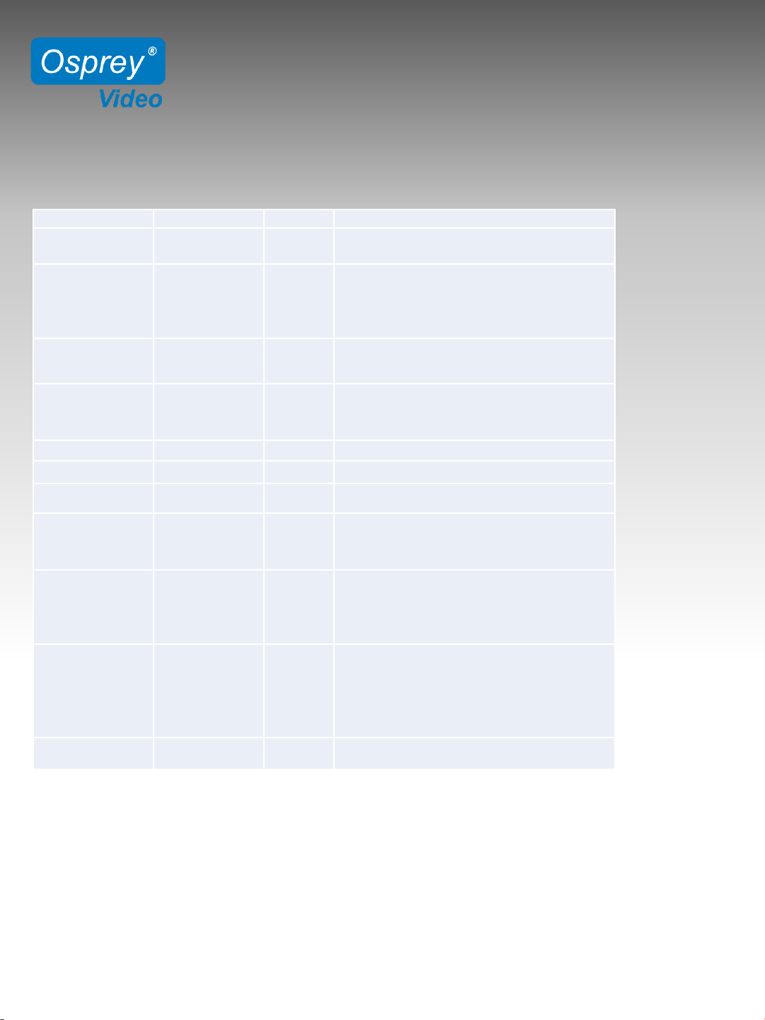
Response from MVS-16 to PC
Note: Broadcast---CMD+ data; Response--- CMD+ status+ data
Data Packet Value Byte Description
Packet Header
0xA5
0x6C
2
The
beginning of data packet.
Data Length
0x0000~0xFFFF
2
The
length of the entire data packet
from
packet
header to end (including
the
packet
header and end). The lower
byte
stays
ahead.
Device Type
0x00~
0xFF
1
Definition
of device type, OXFF
means
broadcast
.
Device ID
0x00~0xFF
1
A distinguishing of the device when there
are several devices in a same LAN at same
time. OXFF means broadcast.
Interface Type
0x00~0xFF
1
0
x00: UART(serial port); 0x01: LAN
Reserve
0x00
9
Reserve
. This device is not reserved.
Command
0x00~0xFF
1
Command
for each function.
Response Status
0x00 ~ 0xFF
1
0
x00: Succeed;
0
x01: Error;
Other
data undefined.
Response
Content
Variable
length
Reserve. The length of response content
is variable when backward reading
command, and it is consistent with the
format of "packet data".
Checksum
0x0000~0xFFFF
2
The
algebraic sum of all bytes from
packet
header
to checksum (including the
packet
header
and checksum). Take 2
bytes,
other
parts omitted. The lower byte
stays
ahead
.
Packet End
0xAE
1
The
end of the packet.
Page 15
RACKMOUNT 16x16 MATRIX SWITCHER
16 CHANNEL MULTI VEWER
MVS-16
www.ospreyvideo.com 15
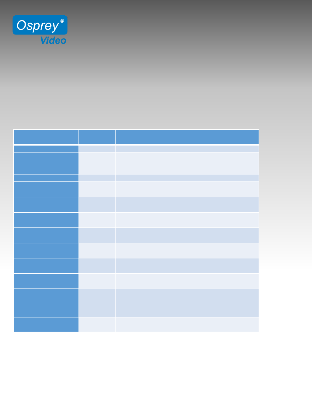
Function
Command
(hex)
Description
Scanning
0xff
Broadcast to scan the multiviewer from the LAN.
Reading All the Data
0x0a
After device scanned, reading all status data of the
device. Find out the device, read the status list of
devices
Output Layout
0x33
Change the output layouts
Output Resolution
0x19
Change the device output resolution.
Value refer to 3.3 output resolution list
UMD Overlay Enable
0x5c
Turn on/off the UMD overlay
1: ON, 0: OFF
Audio Meter Enable
0x5b
Turn on/off the audio meter.
1: ON, 0: OFF
OSD Enable
0x5d
Turn on/off the OSD.
1: ON, 0: OFF
Audio Alarm enable
0x56
Turn on/off the audio alarm function
1
: ON, 0: OFF
Time Code Enable
0x5e
Turn on/off time code
1
: ON, 0: OFF
Operating Mode
0x62
Change
the mode between Multiviewer and Switcher
0
:Multiviewer, 1: Switcher
Matrix Switcher Input
and Output
Correspondence
0x5a
One to one correspondence between input and output
under Matrix Switcher Mode
E.g.: input SDI1 output SDI 1, input SDI2 output SDI 2,
and so forth
Change Matrix
Switcher Input
0x34
Change the input sources under Matrix Switcher mode
Device Type and Commands
Device Type: 0xa3
Commands:
Page 16

RACKMOUNT 16x16 MATRIX SWITCHER
16 CHANNEL MULTI VEWER
MVS-16
www.ospreyvideo.com 16
Partial Parameter List:
Response Format
typedef struct
{
unsigned char value:6; // output resolution
unsigned char signal:1; //OSD enable 1 on 0 off
unsigned char res:1; //Reserved
}Reso_Byte;
typedef struct
{
unsigned char uEn:1;
unsigned char Color:4;
unsigned char BGColor:5;
}Text_Dsip;
typedef struct
{
unsigned char char_len; // UMD length
unsigned char char_buf[34]; //UMD text //
}Umd_String;
typedef struct
{
unsigned char AudioBarEn:1; //Audio meter in each window
unsigned char AuidoDeCh:4; // Audio de-embedding channel select
Reso_Byte InReso; // Read resolution from FPGA, the first 6bits means value
being read,7bit means whether there is signal, 8bit is reversed.
Text_Dsip InputInfo; //Input resolution color (OSD color)
Text_Dsip TimeCode; //Time code color
Text_Dsip AudioAlarm; //Audio alarm
}Osd_View_Cfg;
typedef struct
{
unsigned char tWinMode; //Mode
unsigned char tOutReso:4; //Output resolution
unsigned char tAudioOutNum:5; //Choose audio from a certain window as the source for audio output
//unsigned char tAuidoDeCh:4; // Audio de-embedded channel
unsigned char tCustom:2; //Select custom mode
unsigned char tAudioBarOnOff:1; //Audio meter enable
unsigned char tUmdOnOff:1; //UMD enable
Page 17

RACKMOUNT 16x16 MATRIX SWITCHER
16 CHANNEL MULTI VEWER
MVS-16
www.ospreyvideo.com 17
unsigned char tInputInfoOnOff:1; //OSD enable
unsigned char tTimeCodeOnOff:1; //Time code enable
unsigned char tAudioAlarmOnOff:1; //Audio alarm enable
unsigned char tBorderOnOff:1; //Border enable
unsigned char tLockStatus:1; //Front panel lock status
unsigned char tDhcpStatus:1; //DHCP status
unsigned char tMatrixFlag:1; //Matrix switcher mode
unsigned char tMulti_InputBuf[16]; //Multiviewer input source
unsigned char tMatrix_InputBuf[16]; //Matrix switcher input source
Text_Dsip tUmdDisp[16]; // UMD setting of 16 windows
Osd_View_Cfg tView[16]; // OSD of 16 windows
}ST_Public_Data;
typedef struct
{
ST_Public_Data stPub; //Data synchronization between PC software and LCD display
Umd_String stUmdStr[16]; //UMD string
unsigned char ucDevNameLen;
unsigned char ucDevName[32];
}ST_MultiView_Set;
Page 18
RACKMOUNT 16x16 MATRIX SWITCHER
16 CHANNEL MULTI VEWER
MVS-16
www.ospreyvideo.com 18
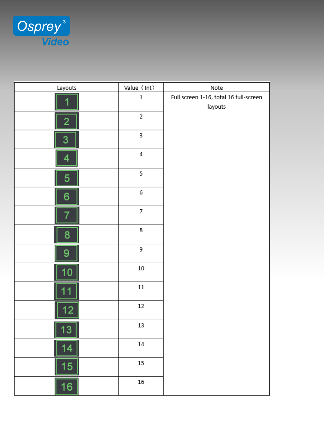
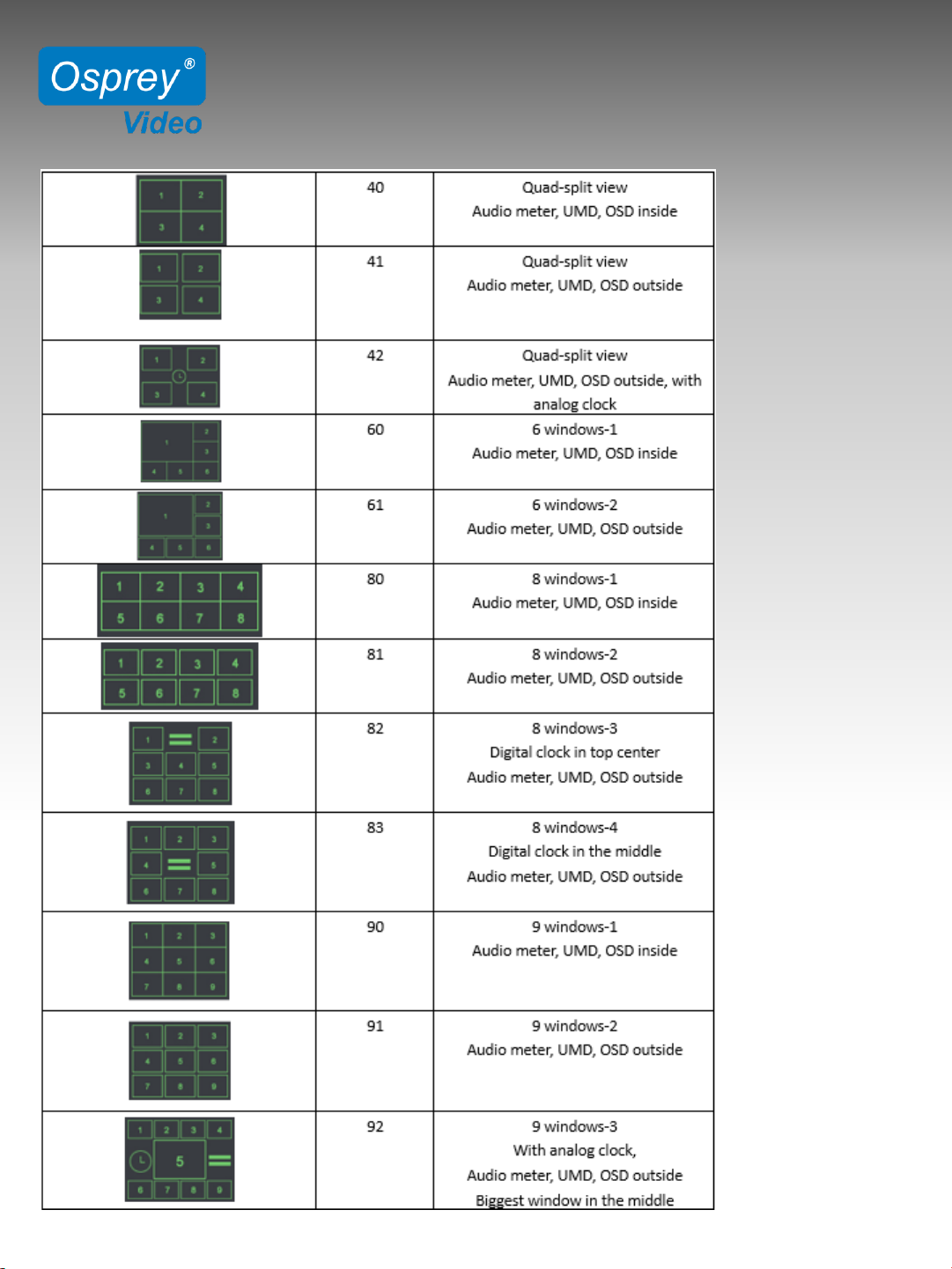
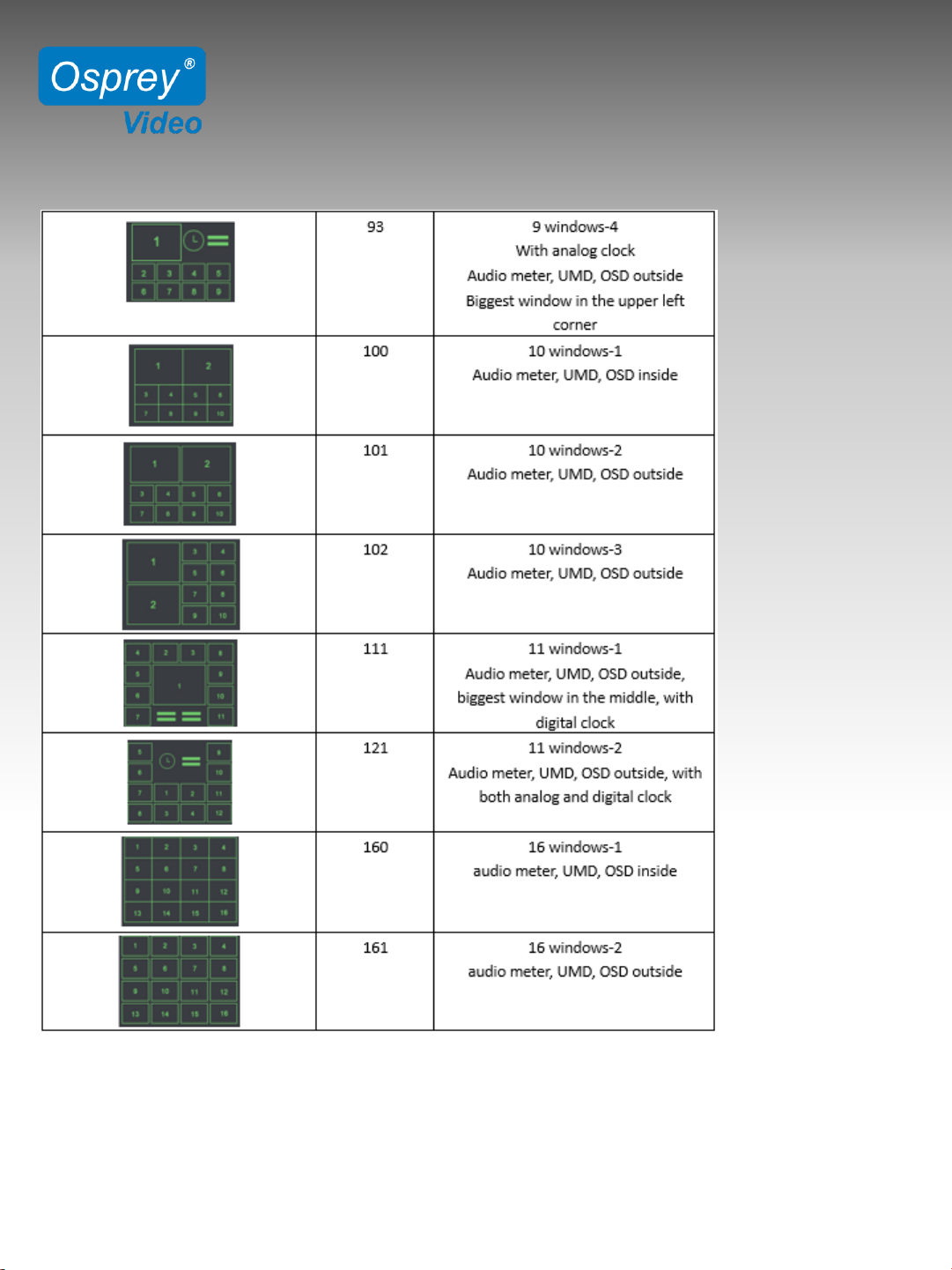
Output Layout List:
Page 19
RACKMOUNT 16x16 MATRIX SWITCHER
16 CHANNEL MULTI VEWER
MVS-16
www.ospreyvideo.com 19
Page 20
RACKMOUNT 16x16 MATRIX SWITCHER
16 CHANNEL MULTI VEWER
MVS-16
www.ospreyvideo.com 20
Page 21
RACKMOUNT 16x16 MATRIX SWITCHER
16 CHANNEL MULTI VEWER
MVS-16
www.ospreyvideo.com 21
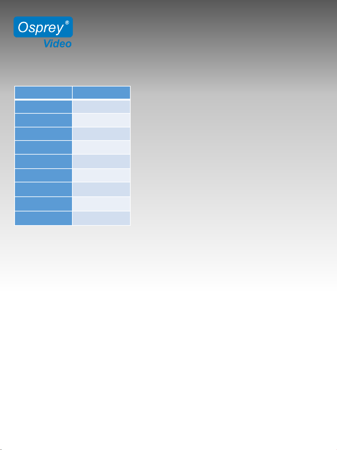
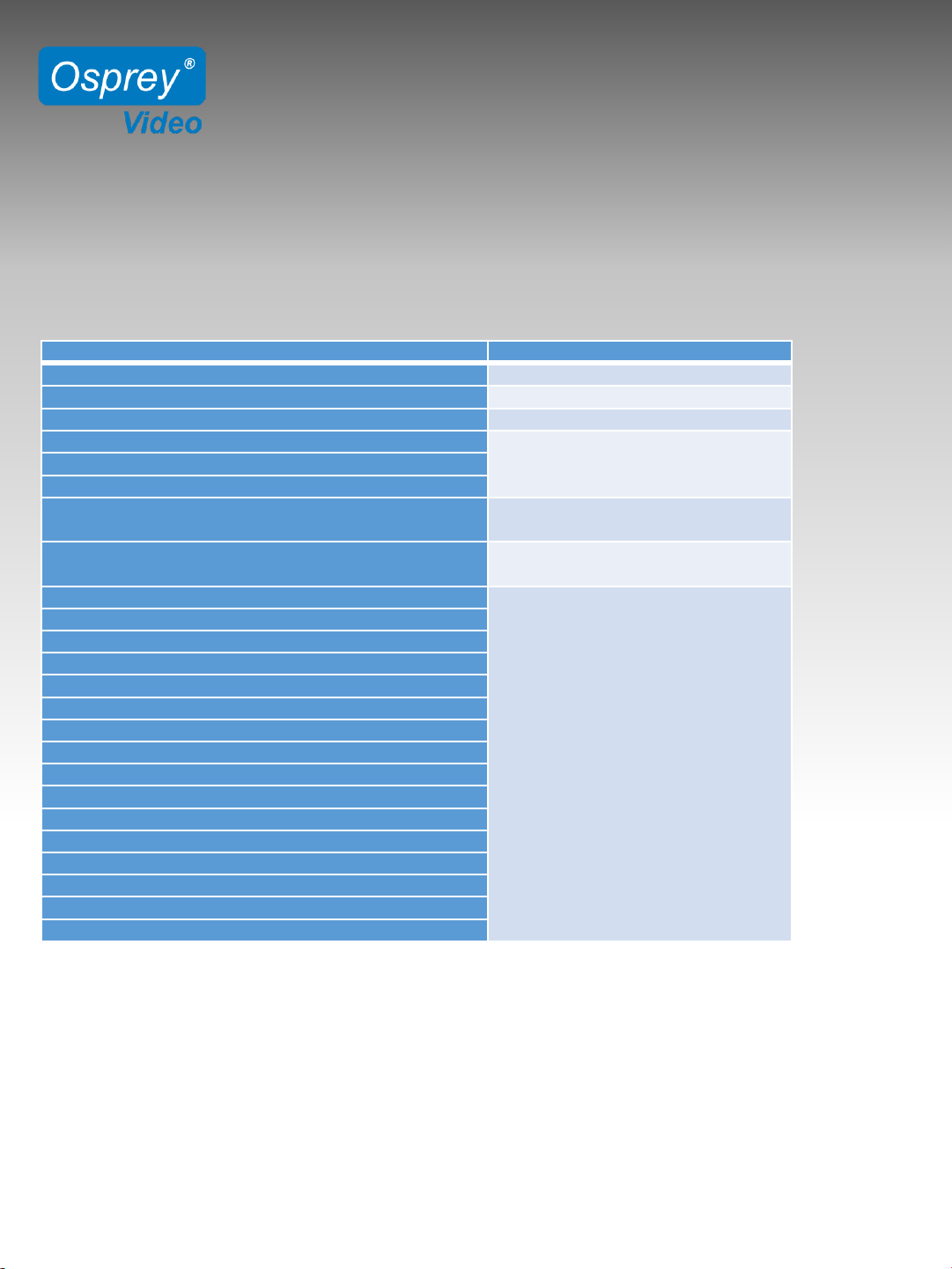
Output Resolution List:
Output Resolution
Broadcast Value
1080p60 0x07
1080p50 0x0b
1080p30 0x03
1080p25 0x0d
1080p24 0x05
1080i60 0x09
1080i50 0x01
720p60 0x0e
720p50 0x06
Examples:
Note 1: Following examples are through LAN port.
If using the serial port just change the interface byte and recalculate the Checksum.
Note 2: All data are hexadecimal.
Note 3: CMD in red, data in green.
Note 4: Every packet data is in couple, including broadcast and response.
4.1 Locating a Switcher on the Network
Method: UDP Broadcast
Packet Format: a5 6c 14 00 81 ff 01 00 00 00 00 00 00 00 00 00 ff a5 03 ae
Destination Address: Broadcast 255.255.255.255
Destination Port: 7000
Response Payload:
a5 6c 2c 00 a1 ff 01 00 00 00 00 00 00 00 00 00 ff 00 31 36 43 48 20 4d 75 6c 74 69 76 69 65 77
65 72 2d 0d 2d 43 04 26 35 95 0a ae
Page 22
RACKMOUNT 16x16 MATRIX SWITCHER
16 CHANNEL MULTI VEWER
MVS-16
www.ospreyvideo.com 22
4.2 Read All Data of the Device’s Current Status
Broadcast
a5 6c 14 00 a1 ff 01 00 00 00 00 00 00 00 00 00 0a d0 02 ae
Above Response Description:
a
5 6c 09 03 a1 ff 01 00 00 00 00 00 00 00 00 00
From
packet header to reserve
0aCommand
byte
00
Response
success
64
Output
layout value
01
Definition of resolution, audio
channel, and others overlay enables
011001
02 03 04 05 06 07 08 09 0a 0b 0c 0d 0e 0f 10
Input channel under multiviewer
mode (Total 16 channel)
01
02 03 06 05 06 07 08 09 0a 0b 0c 0d 0e 0f 10
Input
channel under matrix
switcher
mode
(Total 16 channel)
0
d 0f
UMD
of 16 windows
From structure
Text_Dsip
0
d 0f
0
d 0f
0
d 0f
0
d 0f
0
d 0f
0
d 0f
0
d 0f
0
d 0f
0
d 0f
0
d 0f
0
d 0f
0
d 0f
0
d 0f
0
d 0f
0
d 0f
Page 23
RACKMOUNT 16x16 MATRIX SWITCHER
16 CHANNEL MULTI VEWER
MVS-16
www.ospreyvideo.com 23
continued
01
03 0d 0f 0d 0f 0f 02
Display
information of 16
windows,
including
resolution, audio
meter,
OSD,
time code, audio alarm
01
03 0d 0f 0d 0f 0f 02
01
03 0d 0f 0d 0f 0f 02
01
03 0d 0f 0d 0f 0f 02
01
03 0d 0f 0d 0f 0f 02
01
03 0d 0f 0d 0f 0f 02
01
03 0d 0f 0d 0f 0f 02
01
03 0d 0f 0d 0f 0f 02
01
03 0d 0f 0d 0f 0f 02
01
00 0d 0f 0d 0f 0f 02
01
03 0d 0f 0d 0f 0f 02
01
03 0d 0f 0d 0f 0f 02
01
03 0d 0f 0d 0f 0f 02
01
03 0d 0f 0d 0f 0f 02
01
03 0d 0f 0d 0f 0f 02
01
00 0d 0f 0d 0f 0f 02
0
c
WIN
1 UMD length
UMD
length and
test of 16
windows,
length
occupies 1
byte, test
occupied
34 byte.
53
00 44 00 49 00 20 00 30 00 31 00 00 00 00 00 00 00
00
00
00 00 00 00 00 00 00 00 00 00 00 00 00 00
WIN
1 UMD text
0
c
WIN
2 UMD length
53
00 44 00 49 00 20 00 30 00 32 00 00 00 00 00 00 00
00
00 00 00 00 00 00 00 00 00 00 00 00 00 00 00
WIN
2 UMD text
0
c
WIN
3 UMD length
53
00 44 00 49 00 20 00 30 00 33 00 00 00 00 00 00 00
00
00
00 00 00 00 00 00 00 00 00 00 00 00 00 00
WIN
3 UMD text
0
c
WIN
4 UMD length
53
00 44 00 49 00 20 00 30 00 34 00 00 00 00 00 00 00
00
00
00 00 00 00 00 00 00 0000 00 00 00 00 00
WIN
4 UMD text
0
c
WIN
5 UMD length
53
00 44 00 49 00 20 00 30 00 35 00 00 00 00 00 00 00
00
00
00 00 00 00 00 00 00 00 00 00 00 00 00 00
WIN
5 UMD text
0
c
WIN
6 UMD length
53
00 44 00 49 00 20 00 30 00 36 00 00 00 00 00 00 00
00
00
00 00 00 00 00 00 00 00 00 00 00 00 00 00
WIN
6 UMD text
Page 24
RACKMOUNT 16x16 MATRIX SWITCHER
16 CHANNEL MULTI VEWER
MVS-16
www.ospreyvideo.com 24
Continued
Note: The above information (starting from cmd, omit return value 0x00) use ST MultiView_Set from
Part 4.1 to extract the data one by one according to the parameters.
0cWIN
7 UMD length
53
00 44 00 49 00 20 00 30 00 37 00 00 00 00 00 00
00
00
00 00 00 00 00 00 00 00 00 00 00 00 00 00 00
WIN
7 UMD text
0cWIN
8 UMD length
53
00 44 00 49 00 20 00 30 00 38 00 00 00 00 00 00
00
00 00 00 00 00 00 00 00 00 00 00 00 00 00 00 00
WIN
8 UMD text
0cWIN
9 UMD length
53
00 44 00 49 00 20 00 30 00 39 00 00 00 00 00 00
00
00
00 00 00 00 00 00 00 00 00 00 00 00 00 00 00
WIN
9 UMD text
0cWIN
10 UMD length
53
00 44 00 49 00 20 00 31 00 30 00 00 00 00 00 00
00
00
00 00 00 00 00 00 00 00 00 00 00 00 00 00 00
WIN
10 UMD text
0cWIN
11 UMD length
53
00 44 00 49 00 20 00 31 00 31 00 00 00 00 00 00
00
00
00 00 00 00 00 00 00 00 00 00 00 00 00 00 00
WIN
11 UMD text
0cWIN
12 UMD length
53
00 44 00 49 00 20 00 31 00 32 00 00 00 00 00 00
00
00
00 00 00 00 00 00 00 00 00 00 00 00 00 00 00
WIN
12 UMD text
0cWIN
13 UMD length
53
00 44 00 49 00 20 00 31 00 33 00 00 00 00 00 00
00
00 00 00 00 00 00 00 00 00 00 00 00 00 00 00 00
WIN
13 UMD text
0cWIN
14 UMD length
53
00 44 00 49 00 20 00 31 00 34 00 00 00 00 00 00
00
00
00 00 00 00 00 00 00 00 00 00 00 00 00 00 00
WIN
14 UMD text
0cWIN
15 UMD length
53
00 44 00 49 00 20 00 31 00 35 00 00 00 00 00 00
00
00
00 00 00 00 00 00 00 00 00 00 00 00 00 00 00
WIN
15 UMD text
0cWIN
16 UMD length
53
00 44 00 49 00 20 00 31 00 36 00 00 00 00 00 00 00
00
00 00 00 00 00 00 00 00 00 00 00 00 00 00 00
WIN
16 UMD text
e
3 21 ae
Checksum
and packet end(2byte
)
+
0xae
Page 25

RACKMOUNT 16x16 MATRIX SWITCHER
16 CHANNEL MULTI VEWER
MVS-16
www.ospreyvideo.com 25
4.3 Output FormatSetting
E.g.: Setting the output resolution to 1080p50.
Broadcast
a5 6c 16 00 a1 ff 01 00 00 00 00 00 00 00 00 00 19 00 0b ec 02 ae
Response Payload
a5 6c 15 00 a1 ff 01 00 00 00 00 00 00 00 00 00 19 00 e0 02 ae
Note: In this command, the first byte after 0x19 must be fixed at 0x00, the following 1 byte is the resolution value.
4.4 UMD Enable
E.g.: Turnon UMD
Broadcast
a5 6c 15 00 a1 ff 01 00 00 00 00 00 00 00 00 00 5c 01 24 03 ae
Response Payload
a5 6c 15 00 a1 ff 01 00 00 00 00 00 00 00 00 00 5c 00 23 03 ae
4.5 Audio Meter Enable
E.g.: Turn on audio meter
Broadcast
a5 6c 15 00 a1 ff 01 00 00 00 00 00 00 00 00 00 5b 01 23 03 ae
Response Payload
a5 6c 15 00 a1 ff 01 00 00 00 00 00 00 00 00 00 5b 00 22 03 ae
4.6 OSD Enable
E.g.: Turn on OSD
Broadcast
a5 6c 15 00 a1 ff 01 00 00 00 00 00 00 00 00 00 5d 01 25 03 ae
Response Payload
a5 6c 15 00 a1 ff 01 00 00 00 00 00 00 00 00 00 5d 00 24 03 ae
4.7 Audio Alarm Enable
E.g.: Turn on audio alarm
Broadcast
a5 6c 15 00 a1 ff 01 00 00 00 00 00 00 00 00 00 56 01 1e 03 ae
Response Payload
a5 6c 15 00 a1 ff 01 00 00 00 00 00 00 00 00 00 56 00 1d 03 ae
4.8 Time Code Enable
E.g.: Turn on time code
Broadcast
a5 6c 15 00 a1 ff 01 00 00 00 00 00 00 00 00 00 5e 01 26 03 ae
Response Payload
a5 6c 15 00 a1 ff 01 00 00 00 00 00 00 00 00 00 5e 00 25 03 ae
Page 26

RACKMOUNT 16x16 MATRIX SWITCHER
16 CHANNEL MULTI VEWER
MVS-16
www.ospreyvideo.com 26
4.9 Switch between Multiviewer and Matrix Switcher Mode
E.g.: Switch to Multiviewer mode
Broadcast
a5 6c 15 00 a1 ff 01 00 00 00 00 00 00 00 00 00 62 00 29 03 ae
Response Payload
a5 6c 15 00 a1 ff 01 00 00 00 00 00 00 00 00 00 62 00 29 03 ae
4.10 One to One Correspondence between Input and Output under Matrix Switcher Mode
Note: No parameter for this command
Broadcast
a5 6c 14 00 a1 ff 01 00 00 00 00 00 00 00 00 00 5a 20 03 ae
Response Payload
a5 6c 15 00 a1 ff 01 00 00 00 00 00 00 00 00 00 5a 00 21 03 ae
4.11 Switching one input to output under matrix switcher mode
E.g.: Switch input 15 to Output 8. Select “SDI 15” from the pull-down list of “OUTPUT 8”
Broadcast
a5 6c 16 00 a1 ff 01 00 00 00 00 00 00 00 00 00 34 0f 08 13 03 ae
Response Payload
a5 6c 15 00 a1 ff 01 00 00 00 00 00 00 00 00 00 34 00 fb 02 ae
Page 27

Sample C# Application
using System;
using System.Collections.Generic;
using System.Linq;
using System.Text;
using System.Threading.Tasks;
using System.Net.Sockets;
using System.Net;
using System.Globalization;
namespace OspreyMatrixSwitcher
{
class Program
{
static void Main(string[] args)
{
Sender s = new OspreyMatrixSwitcher.Sender();
s.Send();
}
}
public class Sender
{
public void Send()
{
UdpClient client = new UdpClient();
client.EnableBroadcast = true;
IPEndPoint broadcastConnAddress = new IPEndPoint(IPAddress.Broadcast, 7000);
byte[] bytes = HexToByte("a56c140081ff01000000000000000000ffa503ae");
client.Send(bytes, bytes.Length, broadcastConnAddress);
IPEndPoint ServerEp = new IPEndPoint(IPAddress.Any, 0);
// Wait for a response
var ServerResponseData = client.Receive(ref ServerEp);
// Type 0x82 is the matrix switcher
Byte type = ((byte[])ServerResponseData)[4];
www.ospreyvideo.com 27
RACKMOUNT 16x16 MATRIX SWITCHER
16 CHANNEL MULTI VEWER
MVS-16
Page 28

Sample C# Application
// A success bit of 0 indicates data returned successfully.
Byte success = ((byte[])ServerResponseData)[17];
bool bSuccess = false;
if (success == 0)
bSuccess = true;
Console.WriteLine(@"Response from with IP address: {0} with type: {1}
and success of: {2}",
ServerEp.Address.ToString(),
String.Format("{0:x2}", type), bSuccess.ToString());
System.Console.WriteLine("Press any key to continue.");
System.Console.ReadKey(); // Hit any key to continue
/* Now we attempt to setup ports on the matrix switch.
* At this point all communication is
* directed on port 7000 of the matrix swicher's IP address
*/
IPEndPoint matrixSwitcherConnectionAddress = new IPEndPoint(ServerEp.Address,
7000);
/* Configure the Matrix switcher for multiviewer mode*/
Console.WriteLine("\r\n Configure the Matrix switcher for multiviewer mode using
command 0x62 ...");
bytes = HexToByte("a56c1500a1ff0100000000000000000062002903ae");
client.Send(bytes, bytes.Length, matrixSwitcherConnectionAddress);
System.Console.WriteLine("Press any key to continue.");
System.Console.ReadKey(); // Hit any key to continue
/* Configure the Matrix switcher for input port 15 to be routed to port 8
*/
Console.WriteLine("\r\nConfigure input port 15 to be routed to port 8 using command
0x34 (Change Matrix Switcher Input)...");
bytes = HexToByte("a56c1600a1ff01000000000000000000340f081303ae");
client.Send(bytes, bytes.Length, matrixSwitcherConnectionAddress);
System.Console.WriteLine("Press any key to continue.");
System.Console.ReadKey(); // Hit any key to continue
www.ospreyvideo.com 28
RACKMOUNT 16x16 MATRIX SWITCHER
16 CHANNEL MULTI VEWER
MVS-16
Page 29

Sample C# Application
/* Configure the Matrix switcher for multiviewer mode*/
Console.WriteLine("\r\n Configure the Matrix switcher for matrix switcher mode
using command 0x62 ...");
bytes = HexToByte("a56c1500a1ff0100000000000000000062012a03ae");
client.Send(bytes, bytes.Length, matrixSwitcherConnectionAddress);
System.Console.WriteLine("Press any key to continue.");
System.Console.ReadKey(); // Hit any key to continue
/* Configure the Matrix switcher for input port 15 to be routed to port 8
*/
Console.WriteLine("\r\nConfigure input port 1 to be routed to port 5 using command
0x34 (Change Matrix Switcher Input)...");
bytes = HexToByte("a56c1600a1ff01000000000000000000340f081303ae");
client.Send(bytes, bytes.Length, matrixSwitcherConnectionAddress);
System.Console.WriteLine("Press any key to continue.");
System.Console.ReadKey(); // Hit any key to continue
/* Configure the Matrix switcher for all input ports to be routed to their
corresponding output work
*/
Console.WriteLine("\r\n\r\nConfigure all the ports to have their input port
correspond to all output ports using command 0x5a...");
bytes = HexToByte("a56c1400a1ff010000000000000000005a2003ae");
client.Send(bytes, bytes.Length, matrixSwitcherConnectionAddress);
System.Console.WriteLine("Press any key to continue.");
System.Console.ReadKey(); // Hit any key to continue
System.Console.WriteLine("Press any key to exit.");
// Close the connection
client.Close();
return;
}
www.ospreyvideo.com 29
RACKMOUNT 16x16 MATRIX SWITCHER
16 CHANNEL MULTI VEWER
MVS-16
Page 30

Sample C# Application
public static byte[] HexToByte(string hexString)
{
if (hexString.Length % 2 != 0)
{
throw new ArgumentException(String.Format(CultureInfo.InvariantCulture,
"The binary key cannot have an odd number of digits: {0}", hexString));
}
byte[] HexAsBytes = new byte[hexString.Length / 2];
for (int index = 0; index < HexAsBytes.Length; index++)
{
string byteValue = hexString.Substring(index * 2, 2);
HexAsBytes[index] = byte.Parse(byteValue, NumberStyles.HexNumber,
CultureInfo.InvariantCulture);
}
return HexAsBytes;
}
}
}
www.ospreyvideo.com 30
RACKMOUNT 16x16 MATRIX SWITCHER
16 CHANNEL MULTI VEWER
MVS-16
 Loading...