

Page 1
Osprey Talon Decoder User Guide
1
<20180425>
Page 2
Osprey Talon Decoder User Guide
2
<20180425>
© 2017 Osprey Video. All rights reserved.
Osprey® is the registered trademark of Osprey Video. Microsoft®, Windows® is a registered trademark of Microsoft Corporation. Any other product names, trademarks, trade names, service
marks, or service names owned or registered by any other company and mentioned herein are the property of their respective companies.
No part of this specification may be reproduced, transcribed, transmitted or stored in a retrieval system in any part or by any means without the express written consent of Osprey Video.
Osprey Video reserves the right to change any products herein at any time and without notice. Osprey Video makes no representations or warranties regarding the content of this document,
and assumes no responsibility for any errors contained herein.
Overview
Thank you for purchasing the Osprey® Talon video encoder from Osprey Video. This user guide provides step-by-step
instructions for installing and using your new video encoder. For the latest Osprey product information and news, visit our
website at www.ospreyvideo.com.
FEEDBACK:
We greatly value your input. Please direct any questions, comments or support issues to
+1 972 488 7156
Some information in this user guide is specific to firmware build
1.10.0.257. If your Talon is using an earlier firmware, please consider
upgrading to the latest version by checking the Osprey website.
Page 3

Osprey Talon Decoder User Guide
3
<20180425>
Getting Started
Before you can use your Osprey Talon encoder, you first need to set up and configure it. This chapter
provides you with the details and step-by-step instructions you need to make your installation as quick
and easy as possible.
Here are three starting requirements:
• AC power source (100 - 240 V)
• IP connection and/or Internet connection on a dynamic host configuration
protocol/domain name server (DHCP/DNS) network
• A ‘configuration host’ system
A configuration host is a networked PC computer running a compatible HTML browser. The browser on
the host will be used to access the configuration web page on the Talon encoder. There is also a small
application called ‘Osprey BOSS’ that is used to locate and identify Talon on the local network. BOSS
works with PC and Linux. Once Talon has been identified on the network any HTML browser can be used
to configure your encoder.
Use the web interface for setting options and controlling your Osprey Talon from another networked
computer.
This section addresses the high-level actions you must perform to physically connect and set up your
Osprey Talon video encoder.
Prerequisites
Before connecting the Osprey Talon encoder, ensure you comply with the following prerequisites:
• All packaged items are undamaged and in working order.
• Your environment meets all starting requirements.
• Safety instructions, notices, and warnings in section 8.0 at the end of this document,
including:
FCC Notice
Environmental Notices
Warnings
Page 4

Osprey Talon Decoder User Guide
4
<20180425>
Contents
Overview ....................................................................................................................................................... 2
FEEDBACK:................................................................................................................................................. 2
Getting Started .......................................................................................................................................... 3
Prerequisites ............................................................................................................................................. 3
Introducing Osprey Talon Decoder ............................................................................................................... 6
Osprey Talon Decoder Product IdentificationOsprey Talon G1 Front Panel Diagram.............................. 6
Osprey Talon G2 Decoder Front Panel Diagram ....................................................................................... 8
Osprey Talon Status Lights ........................................................................................................................ 9
Web Interface ............................................................................................................................................. 10
Login ........................................................................................................................................................ 10
Tab ID ...................................................................................................................................................... 11
System Control Tab ................................................................................................................................. 12
Talon IP Setup ......................................................................................................................................... 12
Device Management ................................................................................................................................... 13
Set Name ................................................................................................................................................. 13
Set Password ........................................................................................................................................... 13
Reboot ..................................................................................................................................................... 13
Update Firmware .................................................................................................................................... 14
Updating via the Talon Web page. ...................................................................................................... 14
Updating via USB thumb Drive ........................................................................................................... 15
NOTE: For all image updates ............................................................................................................... 15
Display Setup ........................................................................................................................................... 16
Display Mode ...................................................................................................................................... 16
Resolution ........................................................................................................................................... 16
Layout .................................................................................................................................................. 17
Decoder Setup......................................................................................................................................... 19
Options ................................................................................................................................................ 19
Input Type ........................................................................................................................................... 19
Zixi Receiver ........................................................................................................................................ 20
Audio ................................................................................................................................................... 20
Decode from file ..................................................................................................................................... 21
Page 5

Osprey Talon Decoder User Guide
5
<20180425>
Audio ................................................................................................................................................... 21
Clone ................................................................................................................................................... 21
Delete .................................................................................................................................................. 21
Status .................................................................................................................................................. 21
LCD Touch Control (only on Talon G2 Decoders) ................................................................................ 22
Appendix 1: Osprey BOSS ........................................................................................................................... 23
Installing Osprey BOSS ............................................................................................................................ 23
Microsoft ............................................................................................................................................. 23
Linux .................................................................................................................................................... 23
MAC OS X ............................................................................................................................................ 23
Locating Talon with Osprey BOSS ........................................................................................................... 24
Additional Operations from BOSS ........................................................................................................... 25
Reboot ..................................................................................................................................................... 25
Clear Configuration ................................................................................................................................. 26
Clear System............................................................................................................................................ 26
Set Recovery IP address .......................................................................................................................... 26
Technical Specs ........................................................................................................................................... 27
Safety and Compliance ........................................................................................................................... 30
Page 6
Osprey Talon Decoder User Guide
6
<20180425>
Introducing Osprey Talon Decoder
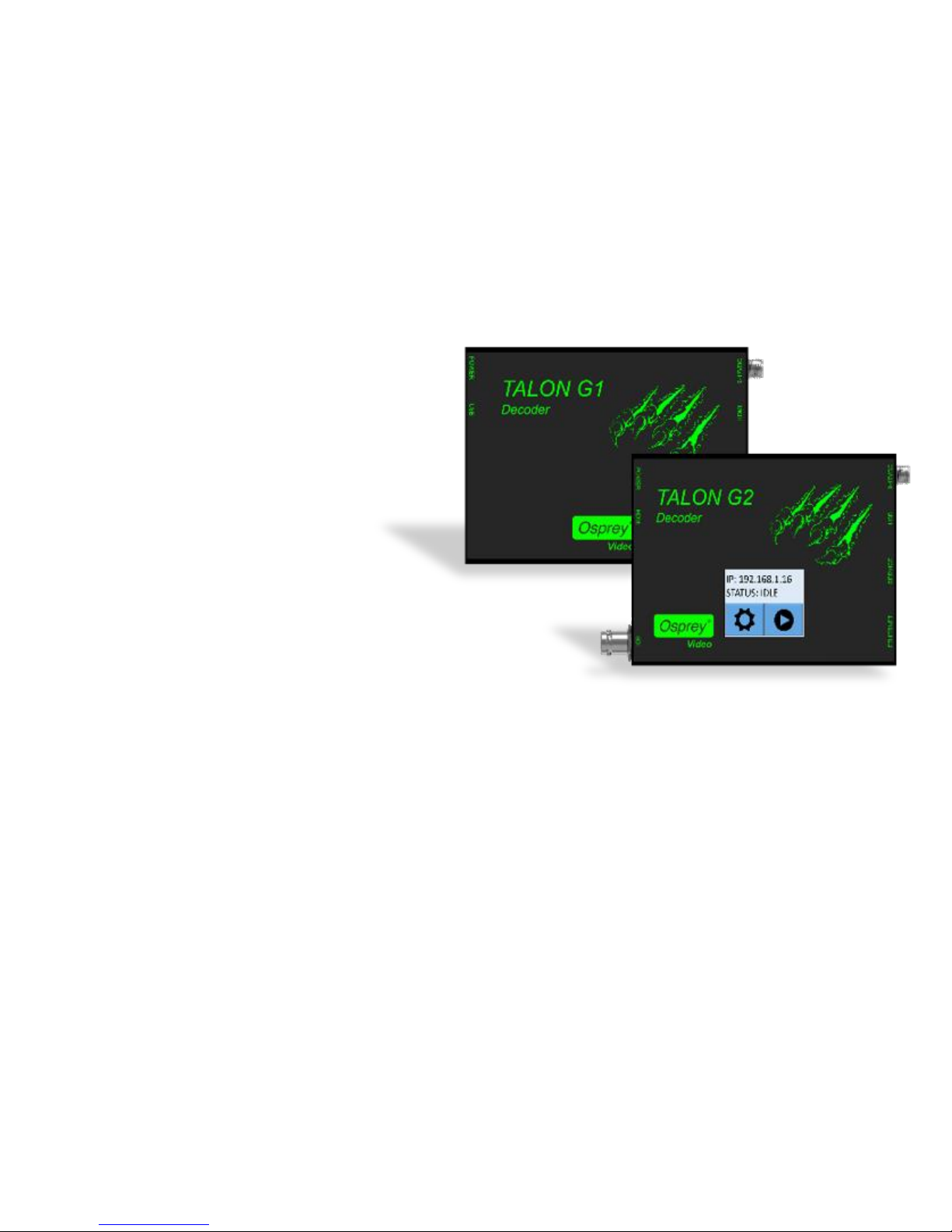
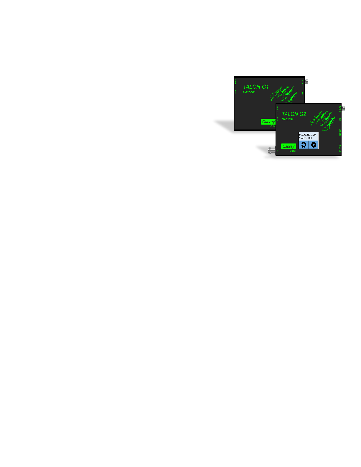
Osprey Talon G1 and G2 hardware-based RTP/UDP decoders are designed for A/V and broadcast
customers tasked with delivering quality point to point video over the unmanaged internet.
Each Talon encoder uses the same web interface and Osprey BOSS utility to access and configure their
features. Functions that are not part of that model are not visible in the web page.
Osprey Talon Decoder Product Identification
Talon G1 H.264 Decoder
HDMI Output
Decodes H.264 RTP and UDP
Streams and .TS Files
.
Talon G2 H.264 Decoder
SDI Output with EIA-608 & EIA-708 Closed
Caption Support
HDMI Output
Decodes H.264 RTP, UDP Streams, and TS Files
Touch Display
Page 7
Osprey Talon Decoder User Guide
7
<20180425>
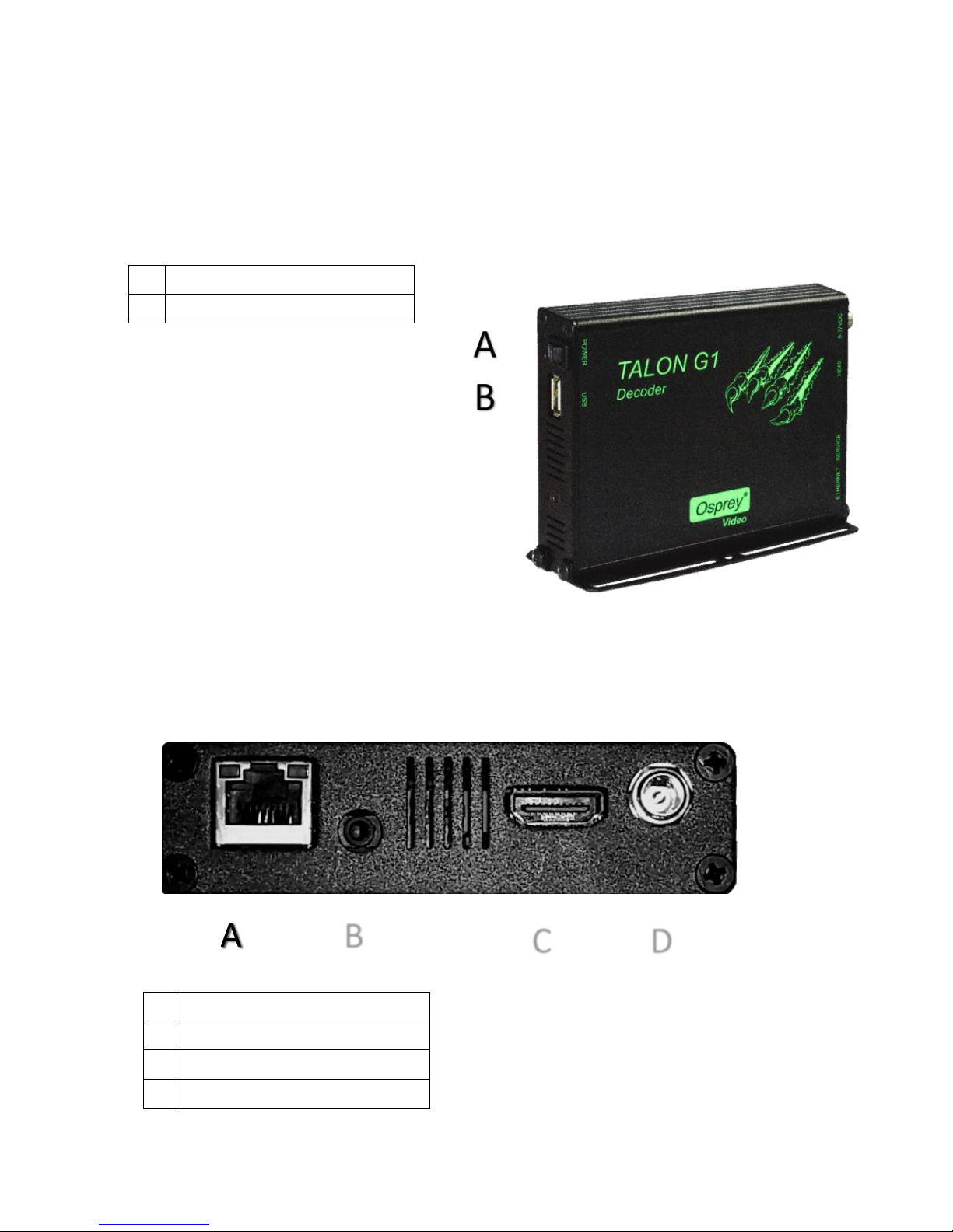
Osprey Talon G1 Front Panel Diagram
You should familiarize yourself with the front panel controls for the Osprey Talon. Besides the basic
buttons for power, start/stop, up/down and menu access, there are indicator lights that are hidden until
illuminated.
A
Power On/Off
B
HDMI Out
Osprey Talon Back Panel Diagram
A
Network (RJ45)
B
Service
C
HDMI OUT
D
Power
A A B C D
Page 8
Osprey Talon Decoder User Guide
8
<20180425>
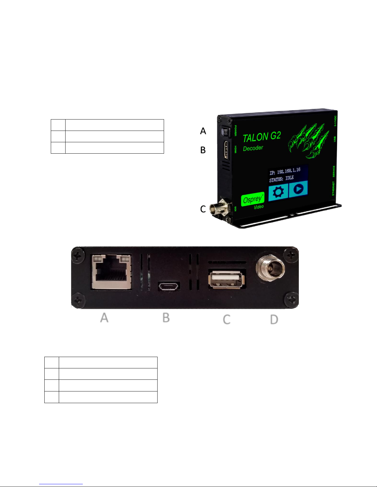
Osprey Talon G2 Decoder Front Panel Diagram
The Talon G2 decoder has several features not found on the G1. The most noticable change is the LCD
Touch Control on the face of the decoder. The G2 also supports simultaneous HDMI and SDI output.
A
Power On/Off
B
HDMI OUT
C
SDI OUT
A
Network (RJ45)
B
Service
C
USB
D
Power
A B C
D
Page 9
Osprey Talon Decoder User Guide
9
<20180425>
Osprey Talon Status Lights
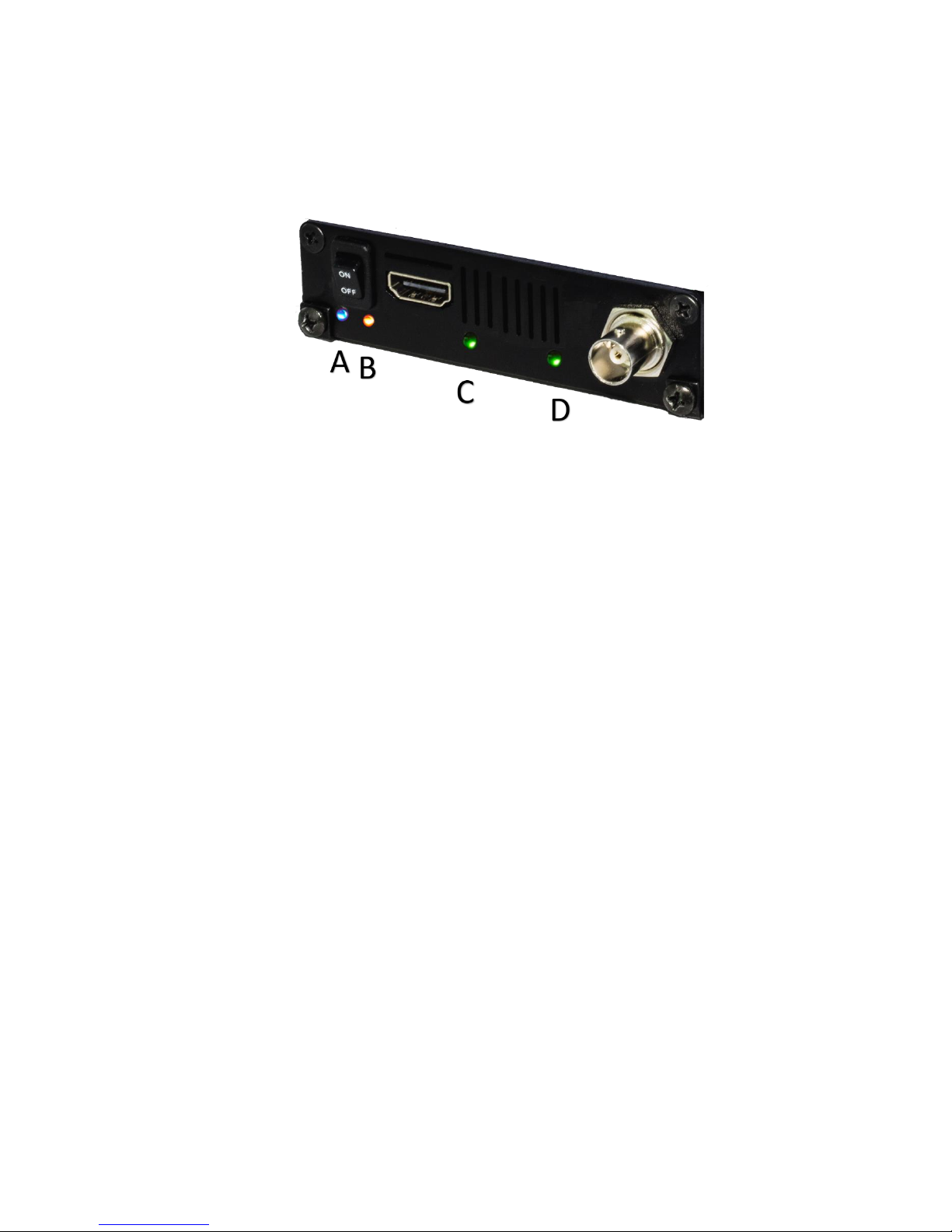
There are four lights on the front panel of Talon G2 that indicate the status of several functions.
A and B: Indicate power and boot status of Talon.
• Single Red indicates that Talon’s power is on but is not ready
• Red and Orange indicates Talon is booting. A and B will flash half way through the boot cycle
• Single Blue indicates that Talon is ready
• Blue an Orange indicates that Talon is decoding
C and D: Green lights after Talon is ready indicate that video output is active.
• C = HDMI
• D = HD-SD/SDI
NOTE: Talon G1 decoder does not have lights C and D
Page 10
Osprey Talon Decoder User Guide
10
<20180425>
Web Interface
Talon is configured and controlled from an internal webpage. This page was designed to provide easy
access to all the configuration features of the Talon. Its simplicity makes it easy to use even from tablets
and smart phones. Once configured, Talon can be stopped and started from the webpage, or from the
LCD Touch Control panel on the front of the decoder.
Login
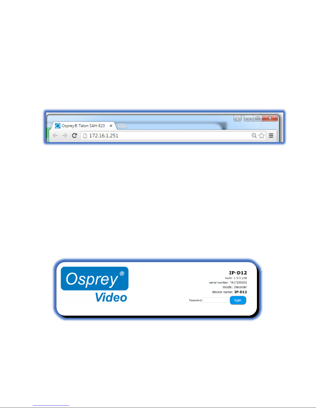
To login to the Talon page, first enter the IP address of Talon in a web browser (show below) and press
enter.
By default, the Talon receives its IP address via DHCP. After Talon boots, the current IP address is
displayed on the LCD Touch Control. Your browser will be directed to the Talon Web Interface. The
default password is ‘osprey’. For increased security always change the default password.
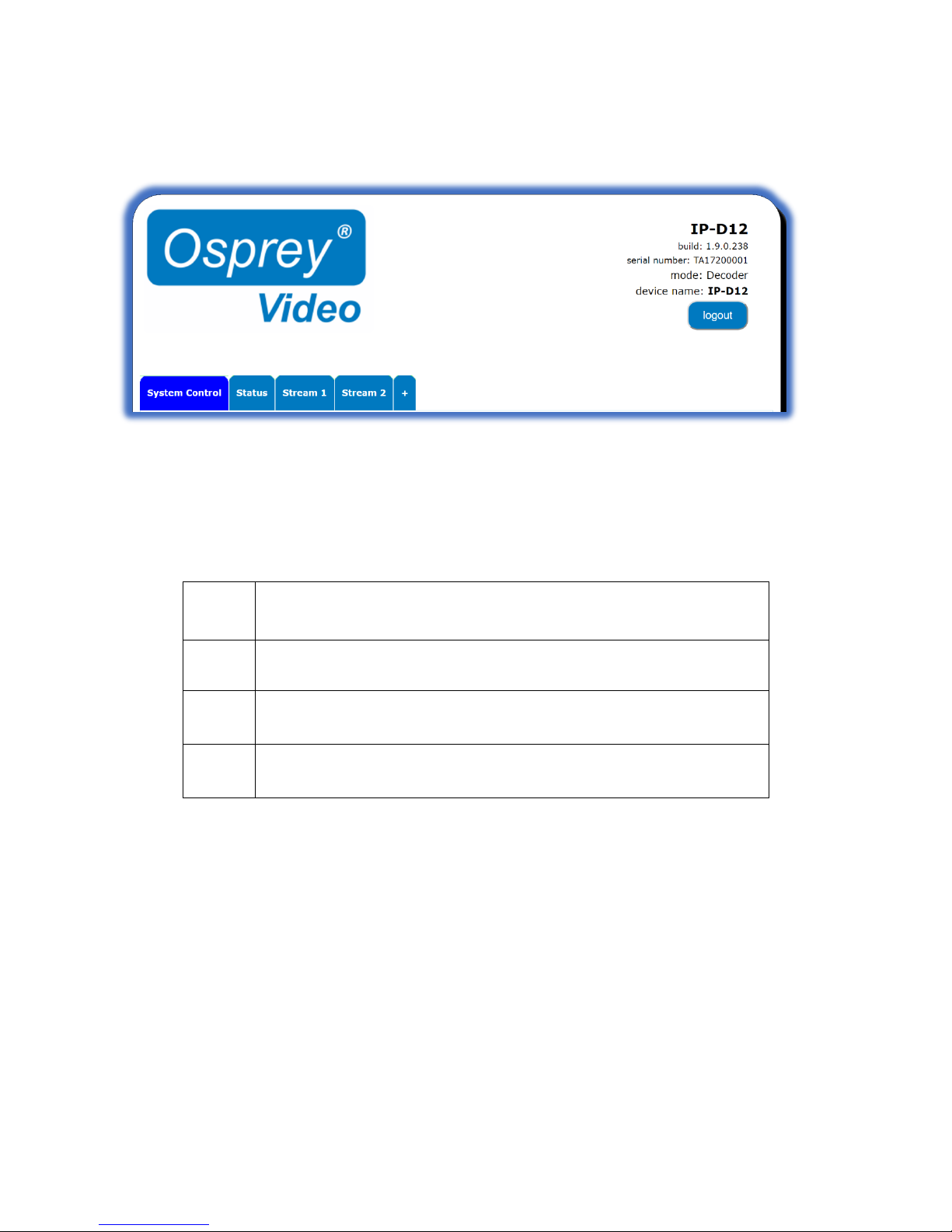
Upon login, you will reach the home page of the web configuration site.
Page 11
Osprey Talon Decoder User Guide
11
<20180425>
Tab ID
The tabs on the front page provide access to the available configuration features of the Talon.
System
Control
IP Setup, Set Device Name, Set Password, Update Firmware, Select
Mode
Status
Displays real time information regarding streams and inputs
Stream
1
Contains all streaming settings for one output stream including source
and output setup.
+
Selecting this item allows you to add additional decoding channels up
to a total of 4.
Page 12
Osprey Talon Decoder User Guide
12
<20180425>
System Control Tab
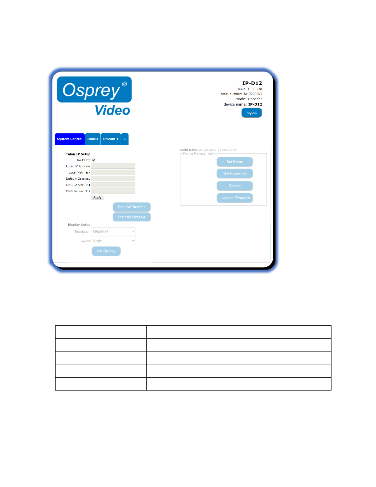
This tab accesses most of the administrative functions of the Talon.
Talon IP Setup
By default, Talon receives its IP address via DHCP. If you need to use a manual address it can be set in
the IP setup dialog box on the System Control page. If you are not familiar with the settings found here
check with your system administrator before changing any settings.
Feature
(default)
Description
IP Address
Automatically Assigned
Sets the IP address
Netmask
Automatically Assigned
Sets the netmask
Gateway
Automatically Assigned
Sets the gateway
Use DHCP
Checked
Enables/Disables DHCP
Page 13
Osprey Talon Decoder User Guide
13
<20180425>
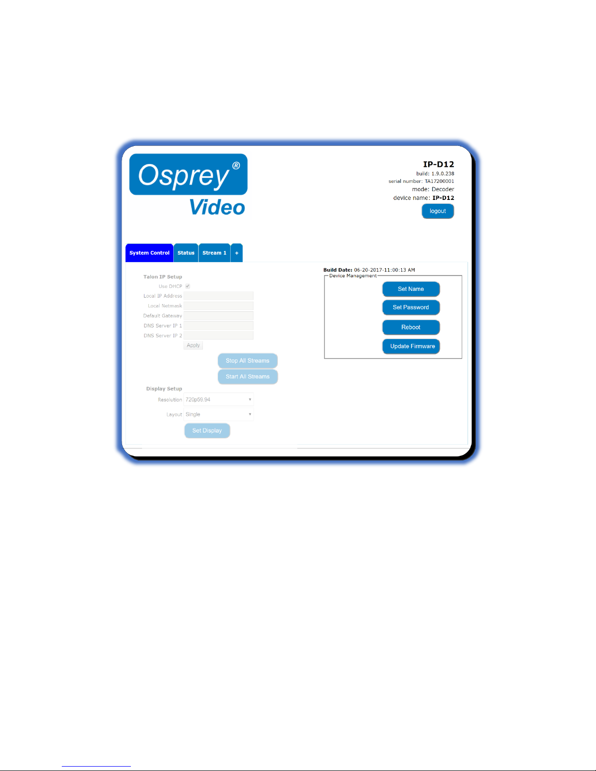
Device Management
Device management tasks allow the configuration of operating system features. These features aren’t
accessed on a regular basis because they are not involved in the configuration of the encoder itself.
Set Name
The model designation for Talon is loaded as the default device name. To easily distinguish multiple
Talons, you can create a new name here.
Set Password
The default password is “osprey”. To maintain device security, it is recommended you change the
default password.
Reboot
Reboot performs a complete power reset of the device. Make sure you save all your settings before
rebooting.
Page 14

Osprey Talon Decoder User Guide
14
<20180425>
Update Firmware
Talon firmware can be easily updated. Osprey recommends that you check the Osprey Video webpage
upon receipt of your Talon to ensure that you have the very latest version. There are two methods.
Updating via the Talon Web page.
1. Download the update from the Osprey Video webpage and save it on the host computer.
2. Login to the Talon via the web page a click the System Setup tab.
3. Click the Update Firmware tab.
4. From the update page click Choose File.
5. From Explorer select the Image file. This can be on the host hard drive or on a USB thumb
drive.
6. Click Upload and Update
7. Talon will install the new image and automatically restart.
Page 15

Osprey Talon Decoder User Guide
15
<20180425>
Updating via USB thumb Drive
If you cannot access the Talon web page, it is possible to update directly from a thumb drive.
• Insert a USB thumb drive in your host computer.
• Format the drive as FAT (do not use FAT32)
• Paste the image file to the root of the thumb drive.
• Insert the thumb drive in the Talon USB port.
• Restart the Talon
• Wait at least 5 minutes until you are certain Talon has restarted.
• Remove the thumb drive
Talon will silently update its image file and restart.
NOTE: For all image updates
Talon stores passwords, IP settings and Saved Profiles in non-volatile memory. These settings will be
saved and made available to the restored image.
Page 16
Osprey Talon Decoder User Guide
16
<20180425>
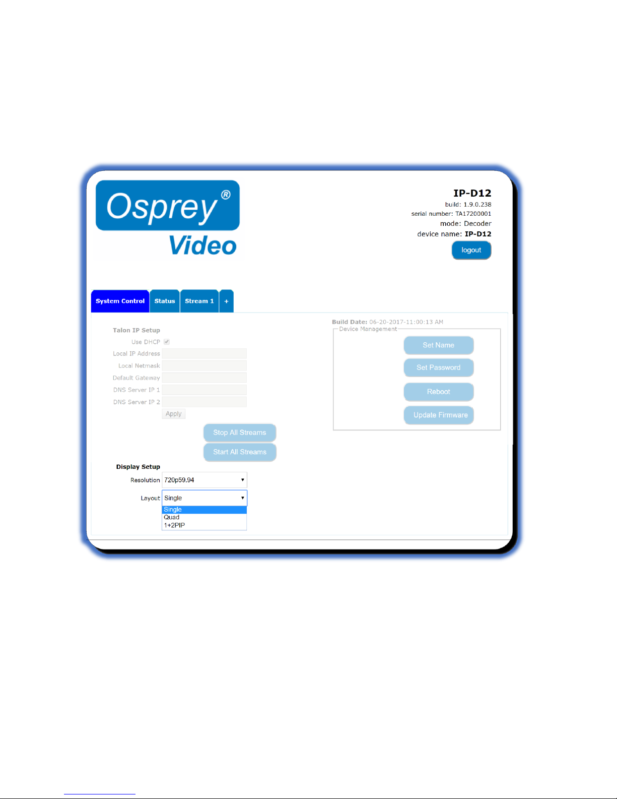
Display Setup
You can set the Display Mode, Resolution and Layout on this page.
Display Mode
Display Mode configures the Resolution and Layout of the decoder output. For model IPSHD-D12 both
HDMI and SDI outputs are active.
Resolution
Set the resolution to match the optimum settings for the display monitor or television.
Page 17

Osprey Talon Decoder User Guide
17
<20180425>
Layout
Available settings are Single, Quad and 1+2PIP. For 1+2PIP the primary video will be Stream 1. To
preserve aspect ratio, the best way to display two streams is to use the “Quad” layout but only start two
streams.
Encodes appear on the screen in the order of the illustration. Stream 1 will always be primary. If you
enable a single stream labeled “Stream 2”, it will not appear in “Single” mode.
NOTE: Layout can be changed while the decoder is running. The screen will go blank for a few seconds
and then resume with the new layout. Any screen section that does not have a stream assigned to it will
appear black.
Page 18

Osprey Talon Decoder User Guide
18
<20180425>
Status
The Status tab provides gives basic status information about all the decoder channels currently running
on Talon. Be sure to refresh the page to ensure your data is current.
Page 19

Osprey Talon Decoder User Guide
19
<20180425>
Decoder Setup
All configuration for actual decoding is found under the tab marked “Stream (1)”. If your interface
doesn’t have a tab marked “Stream” simply click on the tab marked “+” and one will be created
automatically. Additional streams may be created by clicking the “+” up to a maximum of 3 streams.
Options
Autostart allows the user to select one or more of the Streams to begin streaming when the power
switch is turned on. This allows for unattended recovery in the event power is lost. The default is
“Disabled”. Be sure to test stream configurations before enabling Autostart. Failure to do so can result
in failure to start.
Input Type
Talon Decoders accept RTP, UDP and Zixi Receiver streams. Select the protocol if the input you wish to
use. If the stream is Unicast, only the Port must be specified. If the stream is Multicast the dialog box
opens to allow the IP address of the stream.
Page 20
Osprey Talon Decoder User Guide
20
<20180425>
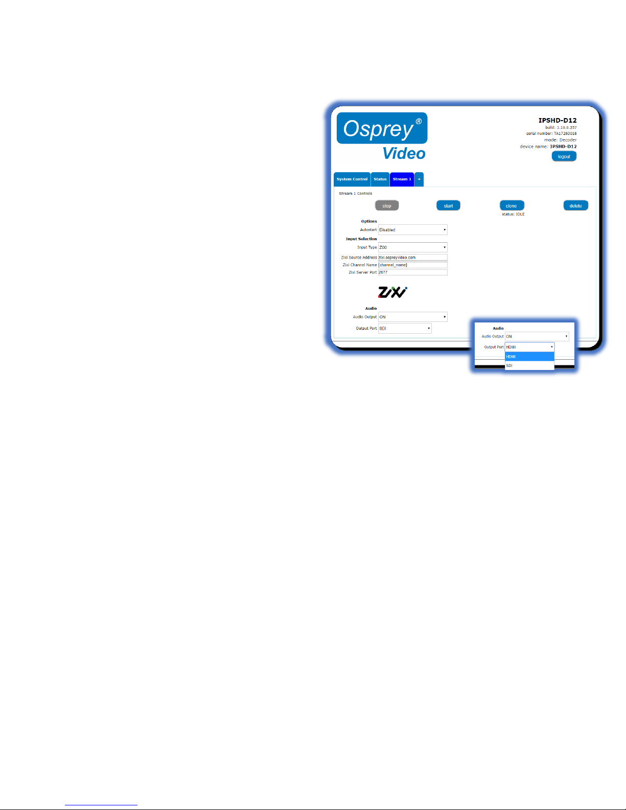
Zixi Receiver
When Zixi is selected as an input type, a different
dialog appears. Put the source address provided by
your Zixi service in the “Zixi Source Address” box
and the channel name in the “Zixi Channel Name”
box. The “Zixi Server Port” defaults to 2077. If your
Zixi service uses a different port be sure to change
that here.
Audio
For all input types, If Audio Output is “ON” you will
need to select the output port. Audio can only be
delivered on one port. From the pull-down select
either “SDI” or “HDMI” as needed
Page 21

Osprey Talon Decoder User Guide
21
<20180425>
Decode from file
Talon will also stream from a .TS file. There is no hard drive on a Talon so you will need to have the file
available on a USB thumb drive.
NOTE: Talon will only mount a thumb drive if
it is formatted in FAT32.
The file location is [filename].ts
All file and folder names are case sensitive.
Audio
Each stream can have an audio output. Note
that any stream that has the audio output set
to “ON” will play. The result could be 4
different audio streams playing at the same
time. Be certain you only activate the audio
stream you wish to hear.
Channel Control Buttons
The buttons in the Stream 1 Control box control the Stop and Start of the encoder labeled Stream 1.
Clone
Often a user wants to create second stream that is very similar to the first, with only minor differences.
You may use the ‘Clone” button to make a second stream configuration that is exactly like the first. Then
it is a simple matter to make the minor change such as address in the second stream without having to
recreate the whole thing.
Delete
Delete completely removes the selected stream configuration.
Status
Indicates whether the stream is running or not.
Page 22
Osprey Talon Decoder User Guide
22
<20180425>
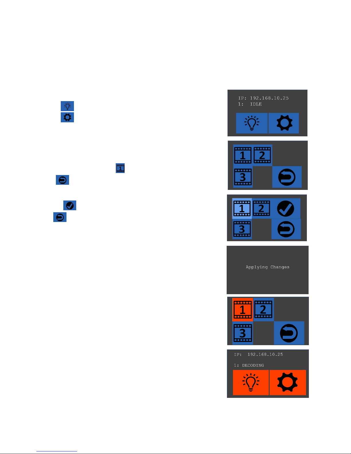
LCD Touch Control (only on Talon G2 Decoders)
Configuration of the Talon G2 is done using the Web interface. Once stream outputs have been
configured, they may be started and stopped with the LCD Touch Control on the front of the encoder. To
configure the streams, use the IP address listed on the Touch Control to point your browser to the
configuration page.
Encoder
Screen
Change
Main Screen
Main Screen icons will be red indicating Talon is
decoding. Status will update for each stream. If
“Error” is shown for any decoder, use the Web
Interface to view details on the error.
Shows IP address and decoder status.
Select to turn off the screen
Select to go to streams screen
Select to confirm changes to the stream
or to return to the Main Screen without
changing
Select Stream by Number to change state
or to return to Main Screen
The stream icon will change to Orange
indicating a running state. Select arrow to
return to main screen.
Page 23
Osprey Talon Decoder User Guide
23
<20180425>
Appendix 1: Osprey BOSS
Osprey® BOSS is a utility application for managing Osprey Talon encoder and decoder systems on a Local
Area Network (LAN). It is an extensible application that currently offers six important functions.
• Locate all Talon encoders on a LAN subnet
• Provide easy access to the Talon web GUI
• Remotely reboot Talon
• Remotely set a temporary IP address
• Clear Talon presets
• Clear System settings
Installing Osprey BOSS
BOSS is available on the downloads tab of www.ospreyvideo.com
• From the downloads tab select “Talon G1 Downloads”
• Select “Osprey BOSS Utility”
• Download the version appropriate to your operating system; Windows®, Linux® or MAC®
Microsoft
• Click and run the Osprey Boss installer
• Launch Osprey BOSS
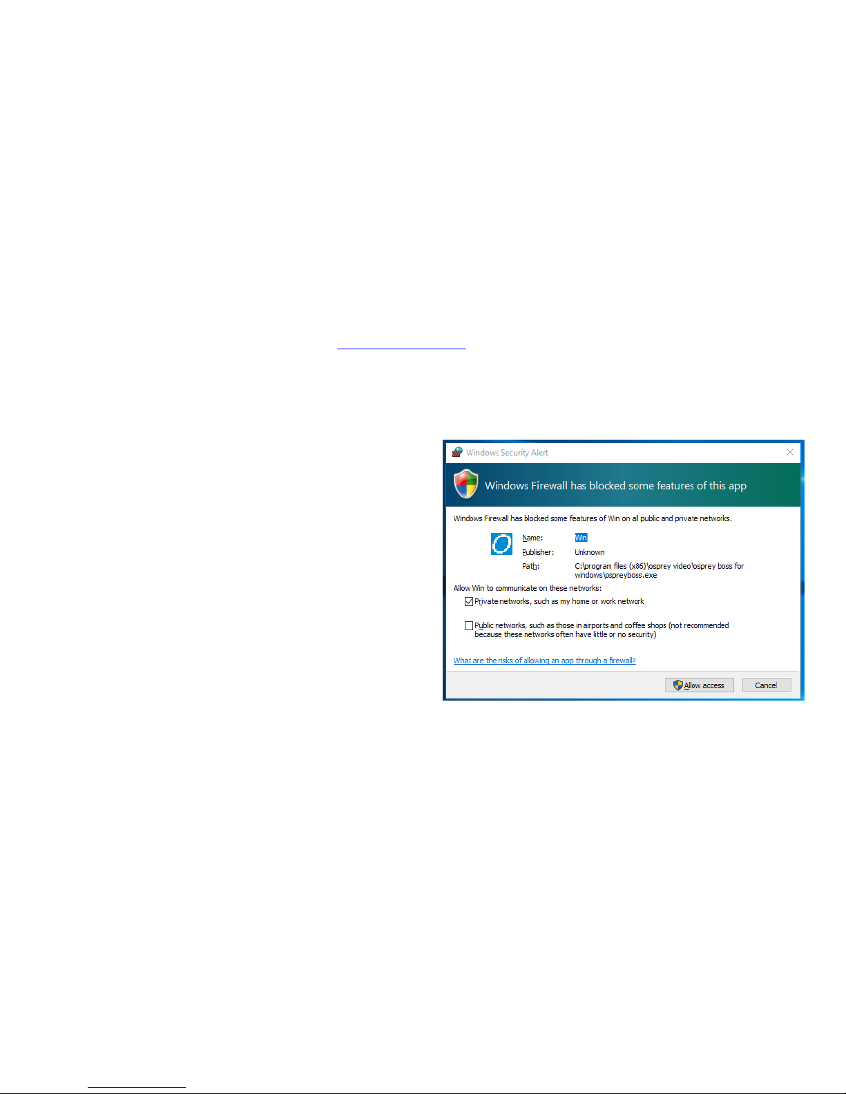
NOTE: The first time the application is
launched you may receive a notification that
some features have been blocked by
Windows Firewall. For Osprey BOSS to work
you will need to authorize it to pass through
the local firewall.
Linux
• Install mono for Linux by going to
http://www.mono_project.com/download/#download/download-lin and following their
instructions
• Extract OspreyBOSS-XXX.tar.gz file to a local folder
• Launch OspreyBOSS by issuing a terminal command “mono OspreyBoss.exe”
MAC OS X
• Install Mono for Mac OS x by going to http://www.mono-project.com/docs/getting-
started/install/mac/ and following their instructions.
• Extract the OspreyBOSS-XXX.zip file to a local folder
• Launch OspreyBOSS by running StartOspreyBOSS
Page 24
Osprey Talon Decoder User Guide
24
<20180425>
Locating Talon with Osprey BOSS
Talon is managed via a web based GUI that can be accessed over the network by most web browsers. All
you need to do is type the IP address of the Talon you wish to access into the address bar of the
browser. The simplest way to determine the IP address is to power up Talon and connect it to the LAN.
Once it is fully booted up and on the network, Osprey BOSS will locate it and notify you of the IP
address.
BOSS can be used if you do not know the exact IP address of your Talon systems. BOSS discovers Talon
devices on the network by broadcasting data packets to all IP addresses within your PC’s subnet (i.e. the
IP range that your PC is currently in). This means that the computer that is hosting BOSS should be on
the same IP subnet as Talon.
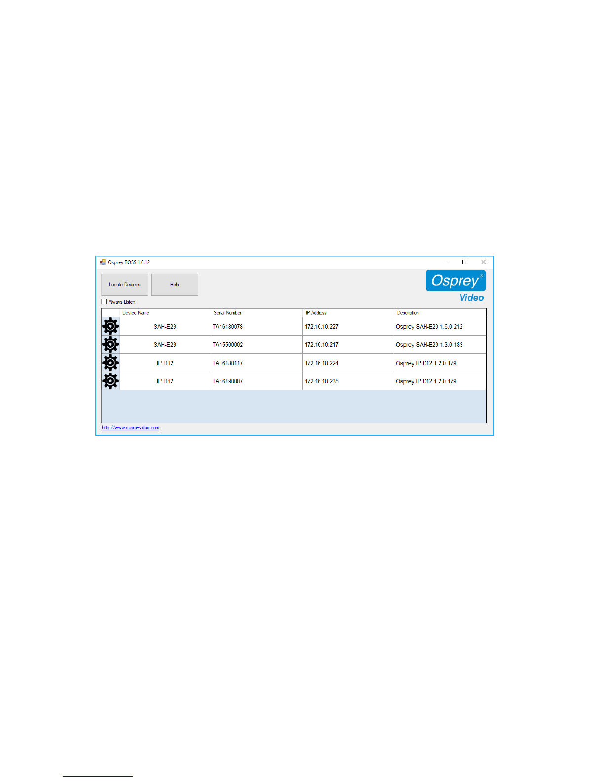
To locate all Talon devices on your subnet, click the “Locate Devices” button on the BOSS interface.
BOSS will populate with the Serial number, Device name, IP and MAC Address along with the Description
for all Talon encoders on this subnet.
To access a specific Talon, click on its Serial Number and you will be taken to the web GUI.
The “Always Listen” check box is only valid for Talon versions 1.6.0.212 and above. Checking will cause
BOSS to continually refresh Talon information without pressing “Locate Devices” again.
Page 25

Osprey Talon Decoder User Guide
25
<20180425>
Additional Operations from BOSS
BOSS also includes other functionality that can be used to manage Talons
• Reboot
• Set a Temporary IP
• Clear Configuration
• Clear System
Reboot
To reboot a Talon from BOSS:
Click the icon.
• Select “Device Control” tab
• Select “Reboot” from the dialog box
• Confirm Reboot
• Wait for Talon to reboot
• Press “Locate Devices” to refresh BOSS
Page 26

Osprey Talon Decoder User Guide
26
<20180425>
Clear Configuration
When this check box is selected, Talon will remove all encoder configurations from memory. You will not
be able to recover them.
Clear System
When this check box is selected, Talon will clear the encoder name and IP address from memory.
Selecting both “Clear Configuration” and “Clear System” will clear all settings and restore Talon to its
factory state.
Set Recovery IP address
Usually a Talon on the network receives its IP address via DHCP. It is possible to assign a static address.
Occasionally, when a static address is used an error can occur whereby the address doesn’t match the
correct specification for that network. When the address is wrong, it is not possible to access the Web
GUI of the Talon. BOSS is still able to locate and identify a Talon with an unreachable IP address, but will
be unable to connect to the Web GUI. For that reason, BOSS includes a utility to assign a temporary
address to allow access to the Web GUI.
To use this utility:
• Click on the icon to the left of the Talon you need to change.
• Select “Set IP” from the dialog box
• In the “Set Device IP Address” dialog, enter valid IP information.
• Press “Locate Devices” to refresh BOSS
• Access Talon by clicking on the name of the Talon you want to reach
IMPORTANT NOTE: The IP address that BOSS assigns is only for accessing the web GUI. Upon successfully reaching the GUI, use
the Talon’s IP configuration to set it to DHCP or manually enter a valid IP address. If you reboot Talon without first resetting its
address in the web GUI you will return to the situation where you started. You will once again have a Talon with an unreachable
IP address.
Troubleshooting Note: BOSS will not locate Talon if:
• Network Discovery is turned off on your Windows PC
• Your Talon is not in the same network segment (VLAN/subnet) as your PC
• Your network is firewall-protected. The UDP broadcast may not be permitted unless Port 10024
is open.
If you are unable to locate Talon, have your network administrator ensure it is on the same physical
and logical section of your network and that broadcast traffic is allowed on port 10024 with a
broadcast address of 224.0.0.212
Page 27

Osprey Talon Decoder User Guide
27
<20180425>
Technical Specs
Technical Specifications
Osprey® Talon G1
H.264 Decoder
Description
_________________________________________________________
Hardware Based H.264 Decoder
Video Input
_________________________________________________________
• H.264 RTP/UDP multicast and unicast
stream
• H.264 .TS file
Max Video Input Capacity
_________________________________________________________
• 1 x 1080p60* or
• 2 x 1080p30 or
• 2 x 720p60 or
• 3 or 4 x 720p30
Video Output Mode HDMI
_________________________________________________________
• 720P 50, 60
• 1080P 25, 30, 50, 60
LED indicators
_________________________________________________________
Power, Unit Ready, Unit Decoding
In the Box
_________________________________________________________
• Talon G1 Hardware Decoder
• International Power Supply
• Mounting Brackets
*100% capacity is based upon pixels per second rather
than bitrate. 1080p60 requires 124MP (million pixels) per
second. Any combined encoding load that equals less
than 124MP per second is acceptable.
Page 28
Osprey Talon Decoder User Guide
28
<20180425>
Technical Specifications
Osprey® Talon G2
H.264 Decoder
Model:
96-02021-01 Osprey Talon G2 Decoder
Description
_________________________________________________________
Hardware Based H.264 Decoder with Dual
outputs and LCD Display
Video Input
_________________________________________________________
• H.264 RTP/UDP multicast and unicast
stream
• H.264 .TS file
Max Video Input Capacity
_________________________________________________________
• 1 x 1080p60*
• 2 x 1080p30
• 2 x 720p60
• 3 or 4 x 720p30
Video Output Mode HDMI and SDI (Parallel)
_________________________________________________________
• 720P 50, 60
• 1080P 25, 30, 50, 60
Closed Caption
_________________________________________________________
• SDI Output with EIA-608 & EIA-708 Closed
Caption Support
*100% capacity is based upon pixels per second
rather than bitrate. 1080p60 requires 124MP
(million pixels) per second. Any combined
encoding load that equals less than 124MP per
second is acceptable.
Touch Display
_________________________________________________________
• IP Address
• Status Indicator Decoding/Idle
• Decoding Start/Stop
• Change Output Resolution
• Change Output Configuration
LED indicators
_________________________________________________________
Power, Unit Ready, Unit Decoding
In the Box
_________________________________________________________
• Talon G2 Hardware Decoder
• International Power Supply
• Mounting Brackets
Page 29
Osprey Talon Decoder User Guide
29
<20180425>
Technical Specifications common to all Talon Decoders
USB Connector
_________________________________________________________
USB Type A 2.0
Ethernet Connector
_________________________________________________________
1 GigE x 1
Software Control
_________________________________________________________
HTTP Based-GUI
Weight
_________________________________________________________
260g
Power Consumption
_________________________________________________________
6W
Dimensions
_________________________________________________________
93.1mm X 120.2mm X 24.75mm (Does not include
mounting brackets or connectors)
Warranty
_______________________________________________________________
2 Years
Compliance
_______________________________________________________________
CE, FCC, ROHS, WEEE
Page 30

Osprey Talon Decoder User Guide
30
<20180425>
Safety and Compliance
FCC Notice
The Osprey Talon has been tested and found to comply with the limits for a Class B digital device, pursuant to Part 15 of the FCC Rules. These limits are designed to provide reasonable
protection against harmful interference in a residential installation. This equipment generates, uses and can radiate radio frequency energy and, if not installed and used in accordance with
the instructions, may cause harmful interference to radio communications. However, there is no guarantee that interference will not occur in a particular installation. If this device does cause
harmful interference to radio or television reception, the user is encouraged to try to correct the interference by one or more of the following measures:
• Reorient or relocate the receiving antenna.
• Increase the separation between the equipment and receiver.
• Connect the computer into an outlet on a circuit different from that to which the receiver is connected.
• Consult the dealer or an experienced radio/TV technician for help.
If the above measures are unsuccessful, please consult the dealer or manufacturer of your radio or television receiver, or speak with an experienced radio/TV technician.
Shielded Cables: Connections between this device and peripherals must be made using shielded cables in order to maintain compliance with FCC radio emission limits.
Modifications: Modifications to this device not approved by Osprey Video could void the authority granted to the user by the FCC to operate the device.
Note to CATV Installer: This reminder is provided to call to the CATV installer’s attention Section 820-40 of the NEC, which provides guidelines for proper grounding and specifies that the cable
ground shall be connected to the grounding system of the building, as close to the point of cable entry as practical.
Product Disposal Information
Dispose of this product in accordance with local and national disposal regulations (if any), including those governing the recovery and recycling of waste electrical and electronic equipment
(WEEE).
RoHS Compliant: Osprey Video is committed to compliance with the European directive on the Restriction of the Use of Certain Hazardous Substances in Electrical and Electronic
Equipment, Directive 2002/95/EC, the RoHS directive.
For current RoHS statement, visit www.ospreyvideo.com
Osprey Video, 1628 Valwood Pkwy, Suite 200, Carrollton, TX 75006 USA
 Loading...