

OSO TERMO RS E Installation Manual

TERMO ELECTRIC BOILERS
MANUAL
OSO TERMO RS -E
OSO TERMO PLUS - E
OSO TERMO PTV – E
B C


Contents
1. Introduction ....................................................................................................................... 1
1.1. Applicable documents................................................................................................. 1
1.2. Retention of documents .............................................................................................. 1
1.3. Features and benefits ................................................................................................. 1
1.4. Termo concept............................................................................................................ 1
1.5. Outside temperature sensor........................................................................................ 1
1.6. Heating curves............................................................................................................ 1
1.7. Termo E Range........................................................................................................... 2
1.8. Water heater temperature sensor ............................................................................... 2
2. Termo E range .................................................................................................................. 1
2.1. Key to TERMO boilers ................................................................................................ 1
2.1.1. RS - E................................................................................................................... 1
2.1.2. Plus - E .................................................................................................................... 3
2.1.3. PTV - E .................................................................................................................... 5
2.2. Expansion Vessel Characteristics (Plus And PTV Boilers) .......................................... 7
2.3. Supply Characteristics 240V N ~ 50/60 Hz ................................................................. 7
3. Installation ......................................................................................................................... 8
3.1. Content included in delivery ........................................................................................ 8
3.2. Standards & Regulations ............................................................................................ 8
3.3. Physical installation..................................................................................................... 8
3.3.1. Select position for boiler ....................................................................................... 9
3.3.2. Fitting the boiler hanging bracket.......................................................................... 9
3.3.3. Recommendations for handling ............................................................................ 9
3.3.4. Removing/fixing the front and top case................................................................10
3.4. Plumbing & Heating installation & commissioning ......................................................10
3.4.1. Installation ...........................................................................................................10
3.4.2. Ancillary components ..........................................................................................10
3.5. Connection to the electrical mains supply ..................................................................11
3.6. Room thermostat, temperature probes and pumps connection ..................................12
3.6.1. Connect room thermostat/programmer................................................................12
3.6.2. Fit external temperature sensor...........................................................................12
3.6.3. Fitting hot water cylinder temperature sensor (PTV-E only) .................................13
3.6.4. Fitting pump connections and expansion vessel (RS – E only) ...............................13
4. Setting up Boilers .............................................................................................................14
4.1. Control Panel (including fault finding indicators).........................................................14
4.2. Choose type of heating (radiator or under floor heating) ............................................15
4.2.1. Hybrid Systems combining radiator and UFH ......................................................16
4.3. Activating system and programming central heating ..................................................16
4.3.1. Heating curves explained. ...................................................................................16
4.3.2. To set correct curve.............................................................................................17
4.3.3. Setting internal temperature ................................................................................17
4.3.4. Programmable room thermostats & setting variable internal temperatures ..........17
5.4. Domestic hot water priority.........................................................................................18
4.5. Protection from freezing.............................................................................................18
4.5.1. Domestic hot water..............................................................................................18
4.5.2. Central heating........................................................................................................18
5. Recommended annual checks (all boilers) .......................................................................19
6. Central heating controls advanced menu..........................................................................20
The company reserve the right to alter size, shape and specification without prior notice

6.1. Domestic hot water advanced menu (control panel type 2) ........................................22
7. Fault finding guide ............................................................................................................24
8. After Sales service information.........................................................................................30
9. Cascade power limiter......................................................................................................30
10. OSO Hotwater UK Ltd ....................................................................................................30
11. Appendices.....................................................................................................................30
11.1. Appendix 1 - Termo RS with space heating and water heating ................................31
11.1.1. Schematic diagram Termo RS - E .....................................................................31
11.1.2. Wiring diagram Termo RS - E............................................................................31
11.1.3. S-Plan wiring layout Termo RS -E .....................................................................32
11.2. Appendix 2 - Termo RS – Space heating only..........................................................33
11.2.1. Schematic diagram Termo RS - E .....................................................................33
11.2.2. Wiring diagram Termo RS-E..............................................................................33
11.2.3. S-Plan wiring layout Termo RS-E ......................................................................34
11.3. Appendix 3 - Termo PLUS E....................................................................................35
11.3.1. Schematic diagram Termo plus-E......................................................................35
11.3.2. Wiring diagram Termo plus-E ............................................................................35
11.3.3. S-Plan wiring layout...........................................................................................36
11.4. Appendix 4 Termo PTV E ........................................................................................36
11.4.1. Schematic diagram Termo PTV-E .....................................................................36
11.4.2. Wiring diagram Termo PTV-E............................................................................36
11.4.3. S- Plan wiring layout Termo PTV-E ...................................................................37
The company reserve the right to alter size, shape and specification without prior notice

Terminology used in this manual
The central heating boiler water circuit is called primary
The domestic hot water is called secondary (dhw)
1. Introduction
Thank you for purchasing the Oso Termo E electric central heating boiler.
To ensure a correct and safe installation and economical use, please read these instructions thoroughly before
installation.
1.1. Applicable documents
The following additional documents are provided with the appliance:
For the owner of the system:
Instructions for use
Warranty card
1.2. Retention of documents
Please pass on this installation manual to the owner of the system. The owner should retain the manuals so that
they are available when required.
1.3. Features and benefits
The boiler provides wet system central heating by passing the primary water over the immersion heaters. The
immersion heaters are located on the under-side of boiler ensuring the elements are constantly immersed in the
heating medium (water with appropriate inhibitor). The primary temperature in the heating circuit is determined by
the outside temperature sensor and the heating curve selected in the boiler, (see sections 1.2, 1.3 and 3.5.3) The
boiler temperature probe will activate and modulate 1, 2 or 3 elements in the boiler to achieve the desired primary
temperature. The boiler has an automatic pump overrun for both central and water heating that prevents a build
up of heat in the boiler. The boiler reservoir is insulated with 19 mm self-extinguishing Armaflex insulating
material, which is sufficient to direct the whole heat only to the heating system.
The boiler operates by rapidly heating a small water quantity. Energy use is maintained at 100% efficiency.
No flue or fan required - Almost silent in operation - No bulk oil storage tanks required
No annual safety check required
For the qualified technician:
Instructions for installation
Electrical drawing for the appliance
1.4. Termo concept.
The OSO Termo E range of boilers uses technology widely used in Europe but relatively new in the UK, that
modulates the boiler to reduce power consumption.
1.5. Outside temperature sensor
An outside temperature sensor is supplied with the boiler to be fitted to an outside shaded wall. This sensor
informs the boiler of the outside temperature.
1.6. Heating curves
The boiler is pre-programmed with a number of heating curves to select from.
The boiler calculates the heat required in the property based on the outside temperature and the set heating
curve – the colder it is outside, the higher the primary temperature needed in the heating system.
Heating curves are set for a particular property and selection is dependent on the insulation levels of the property.
Modern, well insulated buildings have a different heating curve to a less well insulated building. A poorly insulated
house will require a higher primary heating temperature.
Heating curves also vary according to radiator or under-floor heating. The factory set heating curve is for a
building constructed to 2000 building regulations with radiator heating. Many boilers therefore will not require
adjustment of heating curve.
Changing the heating curves at the time of installation is a simple process for the installer. A table is shown on
page 20 indicating which heating curve is required for the building type. Once the heating curve is correctly set, it
should never require changing.
The heating curve will aim for the property to be heated to 22°C. Not all households wish for the same internal
temperature, if the residents of the property require a higher or lower temperature, the selected curve should be
offset up or down by the appropriate number of degrees. Full instructions are given on page 19.
A room thermostat (not supplied) must be installed to finely regulate internal temperatures.
The company reserve the right to alter size, shape and specification without prior notice
Page 1

1.7. Termo E Range
TERMO RS E is a boiler and software package only. Expansion vessel, pump and motorized valves are not
supplied
TERMO Plus E is a system boiler for central heating only. Expansion vessel & pump is supplied in the boiler.
TERMO PTV E is a system boiler for central heating and will provide heat for a domestic hot water cylinder. For
ease of reference the boilers will be referred to in this installation manual as RS E, Plus E and PTV E.
TERMO boilers are available in (240V single phase): 4.8, 6, 7.2, 10.8, and 14.4 kW. OSO Termo boilers can be
connected together to provide more power, the boilers can also be supplied for use on three phase supplies.
Please contact Oso for details.
1.8. Water heater temperature sensor
The Termo PTV E boiler is supplied with a temperature probe that is inserted between the cylinder wall and
insulation or in a dry pocket. This probe then relays cylinder temperature information back to the boiler. The boiler
will then produce sufficient heat to raise the temperature of the domestic water to the desired level.
The company reserve the right to alter size, shape and specification without prior notice
Page 2
2. Termo E range
2.1. Key to TERMO boilers
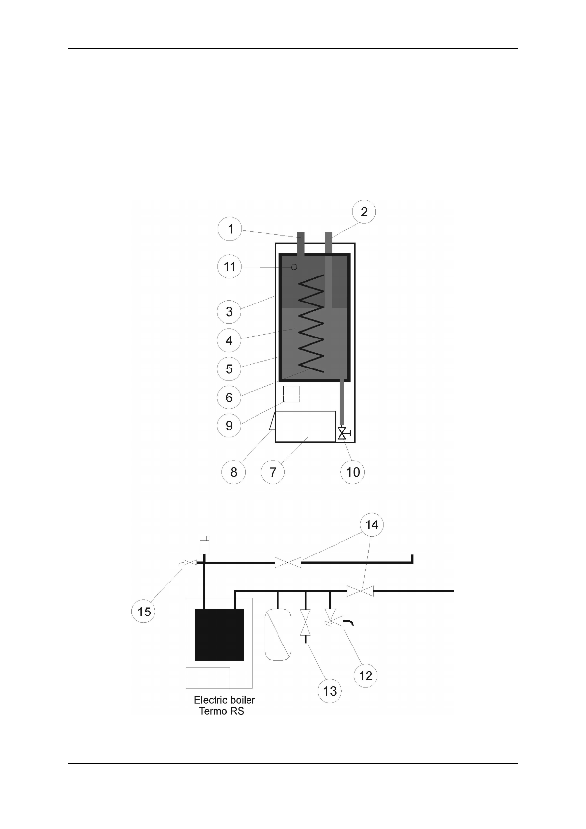
2.1.1. RS - E
1. Primary flow
2. Primary return
3. External boiler jacket
4. Boiler
5. Armaflex Insulation
6. Immersion heaters
7. Control panel
8. Cable entry point
9. Contactors and RCD switch
10. Charge and discharge val ve
11. Pocket with temperature probe
12. Safety valve (supplied loose)
13. Drain valve (not supplied)
14. Isolation valves (not supplied)
15 Manual venting valve (not
supplied)
The company reserve the right to alter size, shape and specification without prior notice
Page 1
RS – E
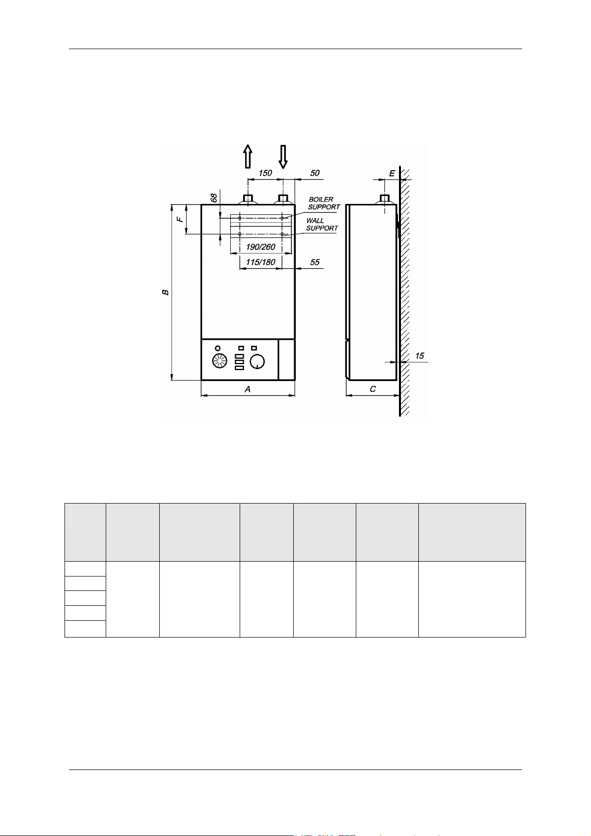
Technical Data For RS E
Power
kW
4.8
6
7.2
10.8
14.4
Boiler
Capacity
Litres
6
Dimensions
A 330
B 750
C 230
D 100
E 57
F 126
mm
Dry
Weight
kg
21.4 0,25 (2,5)
Maximum
primary
operating
pressure
MPa (bar)
Connection
BSP male
¾”
Power supply
240V N ~ 50/60 Hz
The company reserve the right to alter size, shape and specification without prior notice
Page 2
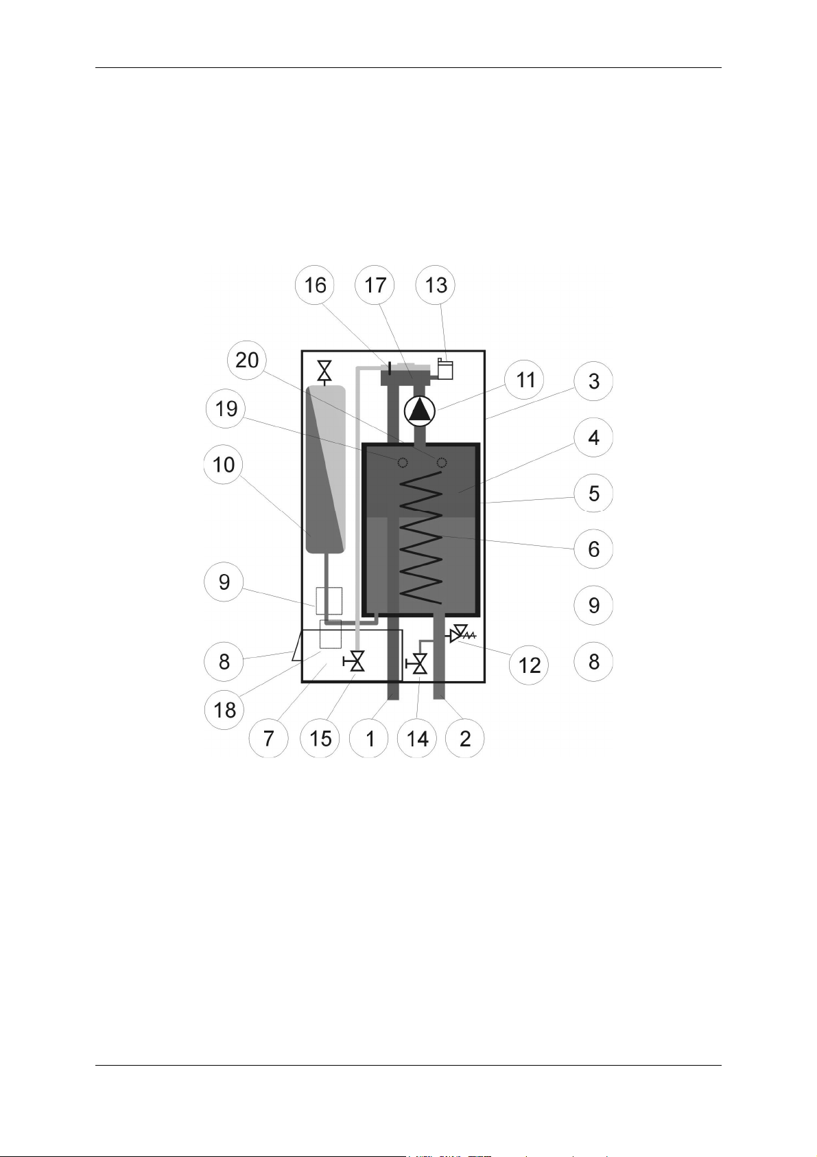
2.1.2. Plus - E
1. Primary flow
2. Primary return
3. External boiler jacket
4. Boiler
5. Armaflex insulation
6. Electrical heaters
7. Control panel
8. Cable entry point
9. Contactors
10. Expansion vessel
11. Circulation pump
12. Safety valve 2.5 bar
13. Automatic air vent (AAV)
14. Charge and drain valve
15. Boiler venting valve
16. Air-indicator
17. Manifold
18. RCD switch
19. Pocket with temperature probe
20. Pressure probe
The company reserve the right to alter size, shape and specification without prior notice
Page 3
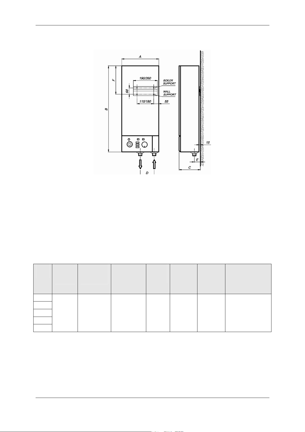
Plus – E
Technical Data For Plus E Boilers
Power
kW
4.8
6
7.2
10.8
14.4
Boiler
Capacity
Litres
6 8 / 0,8
Expansion
vessel
L/bar
Dimensions
Mm
A 330
B 930
C 230
D 100
E 65
F 320
Dry
Weight
kg
34.5 0,25 (2,5)
Maximum
primary
operating
pressure
MPa (bar)
Connection
BSP male
¾”
Power supply
240V N ~ 50/60 Hz
The company reserve the right to alter size, shape and specification without prior notice
Page 4
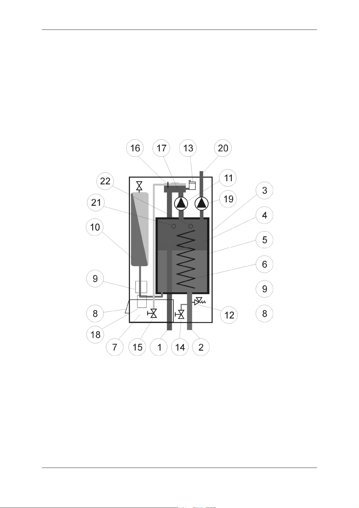
2.1.3. PTV - E
1. Primary flow
2. Primary return
3. External boiler jacket
4. Boiler
5. Armaflex insulation
6. Electrical heaters
7. Control panel
8. Cable entry point
9. Contactors
10. Expansion vessel
11. Circulation pump
12. Safety valve 2.5 bar
13. Automatic air vent (AAV)
14. Charge and drain valve
15. Boiler venting valve
16. Air-indicator
17. Manifold
18. RCD switch
19. Pump for water cylinder
20. Primary flow for water cylinder
21. Pocket for temperature probes
22. Pressure probe
The company reserve the right to alter size, shape and specification without prior notice
Page 5

PTV- E
Technical Data For PTV- E Boilers
Power
kW
4.8
6
7.2
10.8
14.4
Boiler
Capacity
Litres
10 10/0,8
Expansion
Dimensions
vessel
L/bar
Mm
A 400
B 930
C 230
D 150
E 65
F 150
G 50
H 305
Dry
Weight
kg
44.2 0,25 (2,5)
Maximum
primary
operating
pressure
MPa (bar)
Connection
BSP male
¾”
cylinder
1”
(heating)
Power supply
240V N ~ 50/60 Hz
The company reserve the right to alter size, shape and specification without prior notice
Page 6

2.2. Expansion Vessel Characteristics (Plus And PTV Boilers)
Volume of
Expansion
Vessel
L
Maximum
Expansion
Vessel
Pressure
MPa (bar)
8 4.0 114 14.4
0.4 (4)
10
2.3. Supply Characteristics 240V N ~ 50/60 Hz
POWER nominal
4.8 kW 20 A B25-1
6 kW 25 A
7.2 kW 30 A
10.8 kW 45 A B50-1
14.4 kW 60 A
current
Filling
Pressure
MPa (bar)
0.08
(0.8)
Maximum
Pressure
In heating
System
MPa (bar)
0.3 (3)
Max Height
Difference
in central
Heating
System
m
10
Effective
capacity of
Expansion
Vessel
L
5.0
Adsorption
Capacity
%
50%
Values are related to working temperature range from 10C to 90C.
MCB Rated short-circuit
B32-1
B63-1
breaking capacity
Icn (EN 60898)
10 kA 15 kA
Rated short-circuit
breaking capacity
Icn (IEC 947-2)
Cable size* RCD switch type
3 x 4 mm2
3 x 6 mm2
3 x 10 mm2
Maximum
amount of
water in
primary
system
L
143 14.4
25-2/0.03 A
40-2/0.03 A
63-2/0,03A or 40-4/0.03 A
80-2/0,03A or 63-4/0.03 A
Maximum
power of
Boiler
kW
*min. conductor's cross-section in mm2 is based on maximum length of 20 m.
The company reserve the right to alter size, shape and specification without prior notice
Page 7
 Loading...