

OSO Super SXD, Super SX, Super SCI, Super SC Installation Manual
1
PLEASE LEAVE THIS MANUAL WITH THE OSO UNIT AFTER INSTALLATION
00142221-04
Installation Manual
Super S
Thank-you for purchasing the OSO Super S unvented hot water cylinder.
Designed to be simple and neat to install, the Super S differs from other unvented cylinders in that all of the
principle connections, including hot and cold water pipes, expansion vessel and primary heating pipes on indirect
units are connected to the top of the cylinder. Full size template is provided to facilitate pipe positioning.
OSO advise that the connecting pipes and electrical cables are xed in place prior to the positioning of the cylinder. Moving
the cylinder into position should be the last thing done before connection of pipes and commissioning of the cylinder.
This manual gives detailed advice for installation and should be read carefully prior to tting any unvented unit. Where
components are supplied only for indirect units, this is clearly shown. OSO Super S cylinders are not suitable for gravity
fed primary systems. In known hard water regions, precautions should be taken to prevent limescale formation in hot water
cylinders, in accordance with Building Regulation Part L, Domestic Heating Compliance Guide.
This OSO cylinder must be installed by a competent person and be installed in compliance with the OSO Installation and
Maintenance Instructions, all current legislation, codes of practice and regulations governing the installation of unvented hot
water cylinders in force at the date of installation.
OSO Hotwater UK Ltd. Super S 4-10
OSO Super S front view
Top view 120-250 l. Top view 300 l.
Contents
Page no.
1. General information ...........................2
2. Cylinder Specications ...................... 3
3. Preparation of installation area ..........3
4. Connection of Pipework .....................4
5. Commissioning and lling up ............. 5
6. Electrical connection ..........................5
7. Safety and Servicing ........................10
8. Fault nding ..................................... 11
9. Technical and Performance specs ... 12
10. Benchmark Logbook........................13
PLEASE READ THIS MANUAL BEFORE INSTALLATION AND LEAVE UNDER THE CYLINDER TOP LID. THE
MANUAL AND ATTACHED LOGBOOK SERVE AS THE CYLINDER GUARANTEE.
For capacities 120 - 300 litres

2
1. General information
1.1 Health and Safety regulations.
Handling Operations Regulations 1992 denes manual handling as: “any transporting or supporting of a load
(including the lifting, putting down, pushing, pulling, carrying or moving thereof) by hand or bodily force” The Regulations
set no specic requirements such as weight limits. However common sense still has to be used based on an ergonomic
approach for each individual. The Super S should be transported and stored in a vertical position.
1.2 Siting the Super S
(the cylinder should not be positioned until the connecting pipework and cables are tted)
There are few restrictions on the siting of the OSO Super S, however it should not be sited anywhere open to frost
attack. The unit should be placed on a stable at surface capable of withstanding the weight of the cylinder when full
(see table on page 12) and access must be allowed for maintenance purposes.
If wall mounted with an OSO wall bracket, the wall should be capable of withstanding the forces generated by the
weight of the full cylinder. Provision should also be allowed for the routing of the discharge pipe away from the cylinder
to an outside point according to building regulation G3. (See page 11 & 15)
1.3 Component Check list
Components supplied with the unit in a separate accessory kit for site tting:
• Expansion vessel with wall bracket (300 l. only).
• Flexible hose for expansion vessel (300 l. only).
• Tundish (including screws).
• Plastic cable clamp.
• Flexible Y-hose.
• Motorised valve (indirect only).
• Elbows (2) for primary heating connections (indirect only).
Components factory tted
• Expansion vessels with T piece connector.
• Flexible hose for expansion vessel.
• Combination valve, includes line strainer, pressure reducing valve,
balanced cold water connection, (for shower or bidet only),
blanking cap for balanced cold water connection, temperature
& pressure relief valve and hot water blending valve.
• Immersion heater(s) - (3kW).
• Thermostats / thermal cut-out.
• Drain Cock.
• Lid for cylinder.
1.4 Supply requirements
An uninterrupted 22mm cold water mains supply is recommended, however if only a 15mm supply is available, this
may be used provided there is sufcient ow rate available.
A minimum standing pressure of 2.5 bar and a ow rate of 20 litres per minute with a 1 bar dynamic pressure
is recommended. The cylinder will operate at lower pressures and ow rates however the performance will be
compromised. The OSO unvented unit is designed for use with supply pressure up to 10 bar. For pressures over 10
bar an additional pressure reducing valve must be tted in the supply pipe to the unit.
1.5 Expansion vessels - description and product use
120-250 l.: Twin expansion vessels (single on 120 litre) are factory tted to the multifunction valve Part K (see g 1,
page 3) using the supplied exible hose.
300 l.:
An expansion vessel is provided to be connected to the multifunction valve Part K (see g. 1, page 3) using the
supplied exible hose.
The vessel(s) accomodate expanded water when the cylinder is heated and prevents the cylinder reaching its maximum working pressure.
1.6 Compatible ttings and components
All thermostatically controlled boilers are compatible with indirect OSO cylinders.
1.7 Non-compatible products.
Solid fuel boilers, wood burning stoves and other non-thermostatically controlled heat sources must not be used with
unvented cylinders.
1.8 Wall mounting
Wall mounting brackets are available for OSO unvented units 120-210 litres capacity.
Documentation supplied
• Installation manual & benchmark logbook
• Template for connecting pipework
• Adhesive for template
• Guarantee card

3
A Pressure reducing valve 3 bar
B Expansion relief valve 8 bar
C Temp.&pressure relief valve 90°C /10 bar
D Hot water blending valve
E Expansion vessels (120-250 l. only)
F Flexible hose and T-piece (120-250 l. only)
G Tundish
H Flexible Y-hose
J Primary ow
K Expansion vessel connection point
L Line Strainer
M Cold water main supply inlet (CW in)
N Balanced cold water connection (Bal. CW)
P Domestic hot water outlet (DHW out)
R Primary return
J
P
N
M
R
3.1 Pipework.
The OSO Super S has all pipework connections at the top of the cylinder with these pipes secured to the rear wall. A
template is provided to assist in the placement of these pipes. Decide where the cylinder is to be positioned and secure
the wall template (using supplied adhesive) with the cross on the back wall at least 326mm from the left wall. Refer to table
C to position the cross at the correct height above the base for the appropriate capacity of the cylinder. Please note that if
the cylinder will be raised on its feet or on a plinth/higher ooring level, the height of the template above the oor will need
to be raised by an equivalent amount.The connecting pipe tails should be tted so they reach out away from the back wall
horizontally, perpendicular to the wall and parallel with each other. Table B shows the exact lengths these tails should be cut
from wall to reach the cylinder connections. If pipes are clipped up the back wall behind the cylinder position, the tails should
be longer. Use the lengths marked “below”. If the pipes approach the template points from above/side, use the lengths
marked “above”. OSO recommend that the discharge pipe should be located at the left side of the cylinder.
3.2 Electrical connections.
The OSO Super S is provided with two channels in the base to lay electrical cables to the cylinder. The channels run
diagonally from the front centre to the rear left and right and allow the installation to be neat with minimum visible cabling. Two
heat resistant 1.5 mm triple core cables are required for each cylinder (only one for SX 120).
Cables should be sufcient length to reach from the junction box, through the base channels and leave the amount of tail
from the front of the cylinder shown in table C to be able to reach the electrical connections. When the cylinder is moved
into position the cables should be fed up another channel behind the casing at the front of the cylinder into the electrical
box. Cables for upper immersion heaters on direct units continue through this box to a higher channel leading to the upper
electrical box. When cables are in place they can be secured using the cable clamp supplied in the ttings bag.
2. Cylinder Specications
3. Preparation of installation area
Tail lengths
from wall/mm
Above Below
Cold feed in 202 242
Hot water out 274 314
Balanced cold out 188 228
Primary ow & return 238 278
Capacity + above Cable tail - indirect (SC) and Cable tail for upper ele-
base/mm lower element direct (SX) / mm ment of direct (SX) / mm
120 755 550 150 935 550 810
180 1045 550 910
210 1185 550 1040
250 1435 550 1170
300 1635 550 1335
Table CTable b
Fig. 1
FronT
E
Fig. 2
rear
Important: 120-250 l. units are factory tted with expansion vessels (E) and exible hose and T-piece (F). The 300 l. is supplied with a separate
expansison vessel and exible hose for tting on the wall next to the unit. The exible hose for the 300 l. is to be tted to connection point (K).
4
4. Pipe Connection & Commissioning
Before connecting the cold supply, ush the cold supply pipework of all ux and debris.
Lift off the cylinder lid allowing access to the combination valve and other connections.
4.1 120-250 l.: Check the expansion vessels and hose connections are tight. 300 l.: Fit the expansion vessel and
bracket on a suitable wall close to the cylinder. Connect the exible hose to the expansion vessel.
4.2 Remove the template and position the cylinder to meet the heating and domestic water pipes.
4.3 Combination valve.
The Combination valve at the top of the cylinder is factory tted and is water-tight. If necessary it can be rotated in either
direction to suit the connecting pipework, up to half a turn without losing its seal.
4.4 Cold mains supply.
Connect the cold mains supply to the combination valve cold feed (Fig. 3).
4.5 Hot water outlet.
Connect the hot water distribution pipe to the combination valve hot
water outlet (Fig. 3).
4.6 Balanced cold water supply (optional).
If no balanced cold supply is required, tighten the supplied blanking cap. If a balanced mains pressure cold water supply
is required to a shower or bidet (over rim type only, ascending spray type requires type AA,AB or AD air gap), remove
blanking cap and connect to the shower or bidet cold supply on the combination valve (2).
(Major shower manufacturers advise tting a mini expansion vessel in the balanced cold supply pipework to accomodate
thermal expansion and prevent tightening of shower controls) Using the balanced cold connection to feed bath taps can
reduce the ow available to the unvented cylinder.
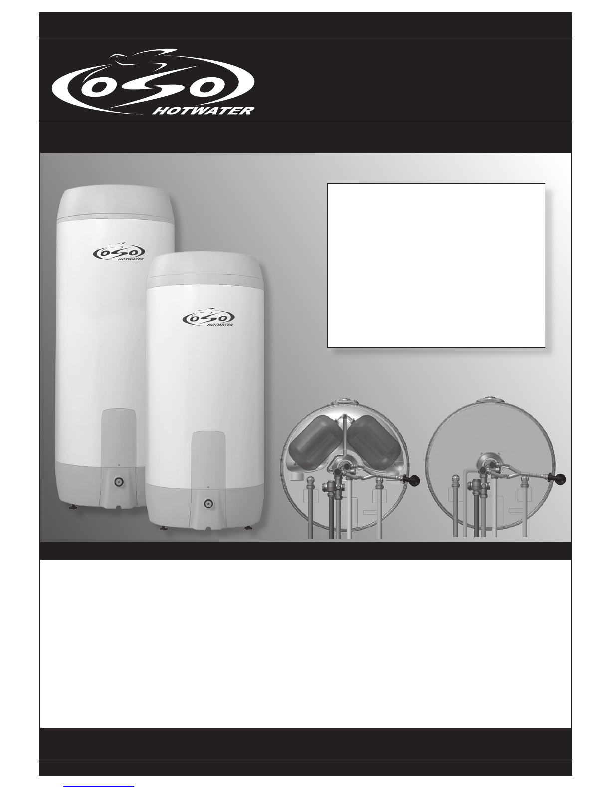
4.7 Flexible Y-hose
The exible Y-hose is preformed to the correct shape. Connect the inlet ends to the expansion relief valve and the
temperature and pressure relief valve.
4.8 Tundish
Recommended position of the tundish is to the left of the cylinder as seen from the front. Connect the tundish inlet to the
outlet end of the exible Y-hose. Tundish should be visible and positioned away from electrical devices. Tundish can be
secured with supplied screws.
4.9 Discharge pipe
Connect the tundish outlet to the discharge pipe. Install the Tundish in a vertical position within a maximum of 500 mm
from the Temperature and Pressure Relief Valve drain connection. Ensure the expansion relief pipework discharges
through the tundish. Tundish pipework must be 22 mm with a minimum vertical length of 300 mm below tundish.
Maximum permitted length of 22 mm pipework is 9 m. Each bend or elbow is equivalent to 0.8 m of pipework. All
pipework must have continous fall and discharge in a safe, visible position. If any doubt, refer to Building Regulation G3.
Discharge pipe must be dedicated to the cylinder and must not be used for any other purpose.
4.10 Primary ow & return and motorised valve (Indirect only)
Fit the elbows supplied to the primary ow & return connections. Make the boiler primary ow and return pipes to the unit.
The motorised valve can be connected to either the primary ow or return pipe. Ensure that the direction of ow is correct.
It is possible to t the motorised valve on the ow pipe on its side to t under the cylinder lid. For electrical connection of the
motorised valve and immersion heater, please read Electrical Installation Instructions. (Pages 5-9)
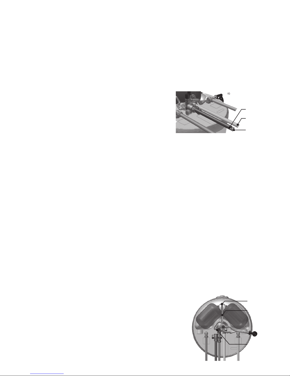
4.11 Secondary return (optional)
If a secondary return is connected, the cylinder thermostats should be set to a
maximum of 60°C. Reduce thermostat settings to 60°C on direct units.
A secondary return can be connected by a T-piece to the combination valve.
Remove the exible hose from the combination valve and connect T-piece.
Connect the exible hose to the T-piece and connect 15mm copper secondary
return to the remaining T-piece outlet. An additional expansion vessel will be
required if the secondary return “loop” exceeds 10% of the cylinder capacity.
1 metre of 22mm pipe holds approximately 1/3 litre of water. 15 mm pipes carry
approximately half that volume. Secondary return must be pumped by a bronze
pump and tted with non return valves to ensure correct direction of ow.
T-piece conn.
(120-250 l. only)
Flexible hose
Fit additional
T-piece here
for optional
secondary
return.
Fig. 4
Fig. 3
Cold mains
supply
Balanced
cold water
Hot water
outlet

5
5. Commissioning and lling up
1. Check all connections for tightness. Open hot water tap furthest away from the OSO water heater.
2. Open the mains stop cock to ll the water heater. When water ows evenly from tap, allow to run for a few minutes
to ush through any dirt, swarf or residue, then close the tap. Open successive hot taps to purge any remaining air.
3. Check all water connections for leaks and rectify if necessary.
4. Manually operate Expansion relief valve B (see g. 1 on page 3) to ensure free water ow through discharge pipe
by turning knob counter-clockwise. To close continue to turn counter-clockwise until the valve shuts.
5. Manually operate Temperature and Pressure Relief Valve C (see g. 1 on page 3) to ensure free water ow
through discharge pipe (Turn knob counter-clockwise).
6. Switch electrical power on.
7. Replace the cylinder lid – this is important as the lid prevents heat loss from the cylinder and combination valve,
conserving valuable energy. Do not place heavy objects on the lid.
Draining & ushing out the system.
Draining.
Switch off the electrical power (Important to avoid damage to element). Isolate boiler from OSO unit. Turn off the cold
water supply valve. Open hot water tap. Open drain at base of cylinder. The unit will drain. Draining process may be
speeded up by opening the temperature and pressure relief valve.
System ushing
will not be necessary under normal circumstances as the line strainer will prevent ingress of foreign
materials, however if ushing is required, run at least 50 litres of water from the cylinder at the highest possible owrate.
Close the taps and follow draining procedure.
6. Electrical installation - all wiring must conform to current IEE regulations
6.1 Immersion heaters
Power to immersion heaters should not be switched on until the unit is lled with water. All indirect units are tted with
one 3 kW immersion heater which is located behind the electrical box. With the exception of the 120 litre all direct units
have two 3 kW immersion heaters. Immersion heaters must be wired through the factory tted thermostat and thermal
cut-out according to diagram on the reverse of the electrical box cover. Alternative thermostats should not be used,
regulations require immersion heaters on unvented cylinders to be connected with a thermal cut-out.
Direct units
Wiring instructions for the immersion heaters are located on the reverse side of the lid. Follow the wiring instructions
connecting the live, neutral and earth as indicated. The unit must be permanently connected to the electrical supply
through a double-pole linked switch with a minimum break capacity of 13 amps. All internal wiring is factory mounted.
The presence of a blending valve in the main hot water valve means that the direct thermostats are factory set to 70°C.
Water will not be delivered to the taps higher than 60°C. This increases the amount of usable hot water available from
the cylinder.
Each immersion heater has a working thermostat adjustable between 40°C - 70°C. A safety cut-out is also incorporated
within the thermostat and will operate at 85°C ± 3°C. Should this happen, check reasons for thermal cut-out button
being released and when satisied press the reset button.
Important:
Before resetting the safety cut-out or altering the thermostat setting, isolate electrical supply to the unit prior
to removal of the lid. Ensure the lid to the electrical box is replaced correctly and the retaining screw is tted.
The lower immersion heater should be connected to the off peak supply (if available) whilst the top immersion heater
can be connected to the day tariff. The immersion heater can be connected to the mains supply through a water heater
controller (Contact your local electricity company if in doubt).
Indirect Units
Motorised valve: To comply with regulations governing the installation of indirect unvented cylinders, a motorised valve
must be tted in the primary pipework. Your OSO unit has been supplied with a two port motorised valve, which will act
as a positive energy cut-out should the safety cut-out operate. The motorised valve will also control the temperature of
the domestic stored water via the cylinder thermostat, which is located in the electrical box. The unit should be installed
on an “S” or “Y” plan system. Please follow the wiring instructions carefully.
The working thermostat which controls the temperature of the domestic hot water (see g. 2) is adjustable between
40°C - 70°C. A safety cut out is also incorporated within the thermostat and will operate at 85°C ± 3°C. Should the
safety cut out be brought into operation, the motorised valve will operate and close down the primary ow to the
cylinder. To reset the safety cut-out and the motorised valve the reset button must be pressed in. If using a 6-wire 28mm
or 1” BSP V4043H on either circuit the white wire is not needed and must be made electrically safe.
OSO Hotwater (UK) Limited can not be responsible if alternative wiring plans are used. Important: Before resetting
the safety cut-out or altering the thermostat setting isolate electrical supply to the unit before removal of the lid.
 Loading...