

OSO Solarcyl IM/SC2 Installation Manual

142044-03
This manual gives detailed advice for installation and should be read carefully
prior to tting any unvented unit.
This OSO cylinder must be installed by a competent person and be installed in
compliance with the OSO Installation and Maintenance Instructions, all current
legislation, codes of practice and regulations governing the installation of unvented
hot water cylinders in force at the date of installation.
Components supplied with the unit for site tting
(See also page 2 for component list)
* Multibloc valve, includes pressure reducing valve, line strainer, balanced cold water take off,
(for shower or bidet only) check and expansion valve and 2 solar sensor pockets.
* Tundish
* 1/2’’F x 15 x 15 tee piece.
* Flexible hose.
* 3/4’’ x 22mm Elbow / Drain Cock.
* Blanking plug
* Motorised valve (indirect only).
Components factory tted
* Immersion heater(s).
* Thermostats / thermal cut-out.
* Temperature and pressure relief valve.
Installation details
The OSO unvented unit is designed for use with supply pressure up to 16 bar. For pressures
over 16 bar an additional pressure reducing valve must be tted in the supply pipe to the unit.
-1-
Health and Safety
Manual Handling Operations Regulations 1992 denes
manual handling as: “any transporting or supporting of a
load (including the lifting, putting down, pushing, pulling,
carrying or moving thereof) by hand or bodily force”. The
Regulations set no specic requirements such as weight
limits. However common sense still has to be used
based on an ergonomic approach for each individual.
DIMENSIONS AND WEIGHTS TABLE 1
PRODUCT REF. 200 250 300 380
HEIGHT 1150 1400 1600 2090
DIAMETER 580 580 580 580
WEIGHT EMPTY 48 60 64 82
MAX WEIGHT FULL 245 301 353 447
COIL SURFACE AREA - M²
UPPER COIL 0,4 0,4 0,4 0,8
LOWER COIL 0,8 0,8 0,8 0,8
-2-
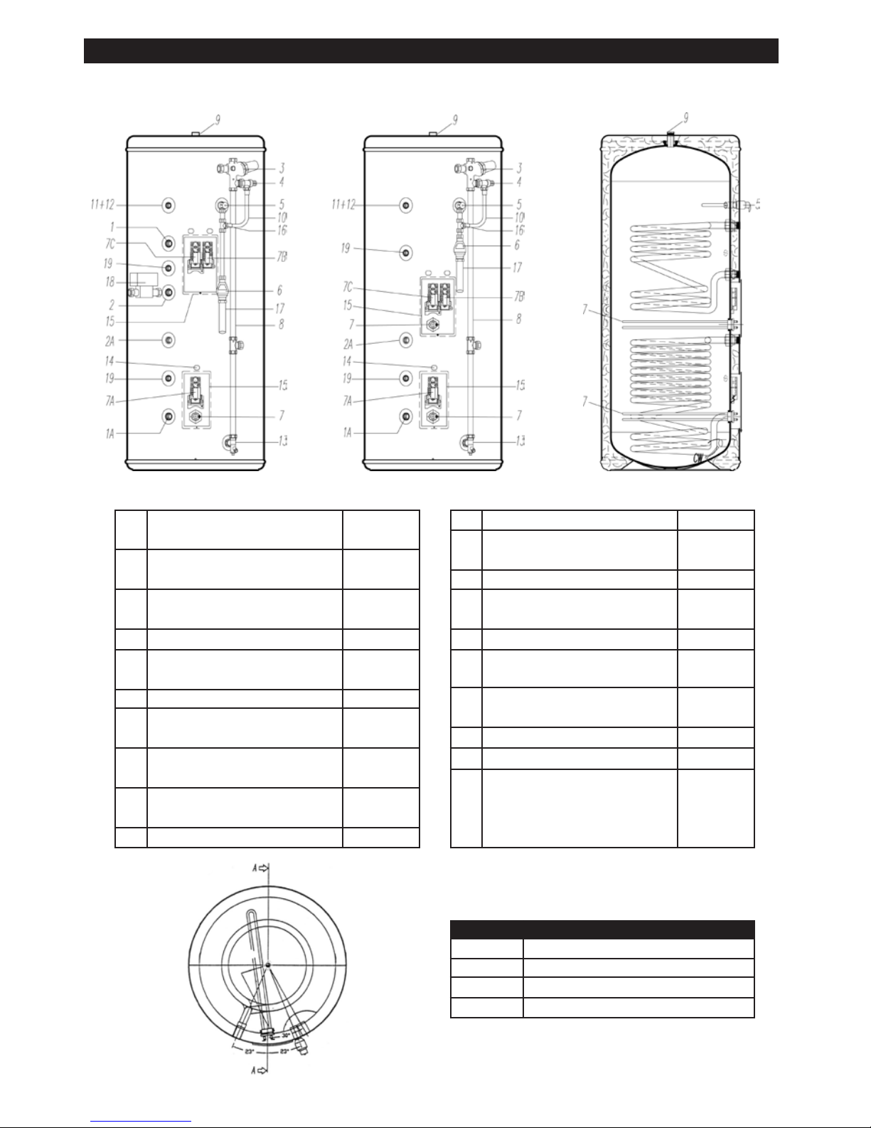
General Layout Fig: 1
1 Return 3/4” BSP Boiler
1A Return 3/4” BSO Solar
2 Flow 3/4” BSP Boiler
2A Flow 3/4” BSP Solar
3 Pressure Reducing Valve Multibloc 355013
Includes Item 4
4 Expansion valve ?
5 Temperature and Pressure 550853
Relief Valve
6 Tundish 219002
7 Immersion Heater 71259
7A Immersion Heater Thermostat 80020
7B Thermostat Boiler 80030
7C Thermostat Solar 80030
8 Cold Feed Tube
(Not supplied see Table 2)
9 Hot Water Outlet 3/4” BSP
10 Flexible Hose 202108
12 Secondary Return Connection
Blanking Plug
13 Elbow / Drain Cock 250445
14 Cable Entry
15 Electrical Box
16 Tee Piece 250006
17 Discharge Pipe (Not supplied)
18 Motorized Valve (Not Factory Fitted) 92000
19 Sensor pockets - 1/2” BSP Female 81019
Series Lenghtoftube(ø22)mm
200 860
250 1060
300 1300
380 1775
KEY Part No. KEY Part No.
TABLE 2
SOLARCYL TWIN COIL
Twin Coil Single Immersion Heater
SOLARCYL SINGLE COIL
Single Coil Twin Immersion Heater
CUTAWAY
(2.1 bar cartridge
REDC 355013)

1. To obtain the best performance from your OSO unvented system it is advisable to feed the unit
with an uninterrupted supply.
2. Before connecting to the multibloc, ush the cold supply pipework of all ux and debris.
3. Locate the water heater in a suitable position to facilitate the installation of the cold water supply,
discharge ttings and pipework. Also take into account access to the immersion heaters and the
commissioning valve.
4. Fit the combined male elbow drain cock to cold supply point (13), so that the compression tting
is vertical.
5. Fit the blanking plug (12) to the secondary return tting. If secondary return is to be used - see point 16.
6. Fit both 1/2’’ male solar sensor pockets to the Solar Sensor bosses (19).
7. Fit the female outlet of the tee piece to the temperature and pressure relief valve (5) with the
horizontal connection facing right at approx. 45°.
8. Fit the tundish (6) to the tee piece using a short length of 15mm copper tube.
9. Fit the length of copper tube 22mm specied in Table 2 to the cold feed elbow (see 4 above) to
include a T piece for expansion vessel exible hose.
10. Fit the pressure reducing valve (3) to the top of the copper tube (see 8 above), so that the black
knob is facing right.
11. Connect the exible hose to the 1/2’’ outlet of the expansion valve (4) and the horizontal outlet
of the tee piece (see 6 above). Discard compression nut & ring.
12. If a balanced mains pressure cold water supply is required to a shower or bidet (over rim type
only), remove the blanking cap from the pressure reducing valve (3) and connect to the shower
or bidet cold supply. Using the balanced cold connection to feed bath taps can reduce the
ow available to the unvented cylinder. (Major shower manufacturers advise tting a mini
expansion vessel in the pipework to accommodate thermal expansion and prevent
tightening of shower controls)
13. Connect the cold supply to the Multibloc (3).
14. Fit the expansion vessel to the wall close to the water heater using the enclosed mounting bracket.
Connect the expansion vessel hose to the T piece in the cold feed pipe to the cylinder.
Hot water supply
15. Connect the hot water supply pipe to the outlet (9). Ensure connection is water tight.
Secondary return (optional)
16. Connect secondary return if required to tting according to diagram on page 16.
Discharge pipe
17. Connect the discharge pipe from the tundish (6). This must have a continuous fall and be tted
in accordance with The Building Regulations (see page 16).
Boiler Primaries
Primary ow & return and motorised valve
18. The boiler primary ow and return connections should be made to the upper coil connections
unit. The motorized valve can be connected to either the primary ow or return pipe. The primary ow
and return ttings are 3/4’’ BSP female. The valve has 22mm x copper connections. The direction of
primary ow in the boiler coil is bottom to top.
19. For electrical connection of the motorised valve and immersion heater, please read Electrical
Installation Instructions. (Pages 7 - 11)
Solar Primaries
20. The Solar ow and return connections should be made to the lower coil connections.
Temperature control from the Solar circuit is achieved using a differential solar controller. This
controller must be wired in series through the thermal cut-out on the OSO thermostat (see gure
4 pages 9 & 11). If Solar Panels are to be installed at a later date then connect the boiler primaries to
the lower coil. The driection of solar primary ow in the solar coil is top to bottom.
21. If the solar primary circuit contains a mechanical shut-off device, ensure that a non return valve
in the circuit prevents thermal syphoning if the circulation is stopped. Should a mechanical shutoff
device not be present, one should be tted and wired in series to the thermal cut-out. Care
should be taken to ensure the device is suitable for temperatures and uids that may be present
in a solar-thermal system.
22. Temperature sensors for the cylinder provided with the differential controller should be inserted
into the pockets provided (see pt 5 above).
-3-
COLD WATER SUPPLY

Filling up
1. Open a hot tap.
2. Open the cold water supply valve
3. when water ows from hot tap, close the tap
4. Allow the system to stabilize for 5 minutes
5. Open each hot water tap in turn to expel air from the system pipe work.
6. Check for leaks.
7. Manually operate Temperature and Pressure Relief Valve (5) to ensure free water ow through
discharge pipe. (Turn knob to left.)
Draining
Switch the electrical power off (important to avoid damage to element). Isolate boiler from OSO unit.
Turn off the cold water supply valve. Open hot water tap close to cylinder. Open drain (13). The unit
will drain.
Safety Cut-out
1. The safety cut-out operates if:
a. Wiring is incorrect.
b. The immersion heater thermostat or cylinder thermostat fails.
c. Thermostat is set too high.
2. Remember before resetting the safety cut-out or altering the thermostat setting, isolate electrical
supply to the unit prior to removal of the electrical box lid.
3. Reduce thermostat setting and press the reset button. After adjustments are completed, ensure
the lid to the electrical box is replaced correctly and the retaining screw is tted.
4. If still out of operation, contact installer.
Cold or tepid water discharge from tundish
1. Close cold water supply valve
2. Open a hot tap.
3. Repressurise the expansion vessel air charge to its set level.
4. close hot tap
5. Open the cold water supply valve
Hot water discharge from tundish
This indicates a malfunction of a thermal cut-out, operating thermostat or the combined temperature
and pressure relief valve. Turn off the electrical supply to the immersion heater and also isolate an
indirect unit from the boiler. Contact the installer or competent engineer.
-4-
COMMISSIONING
SAFETY AND MAINTENANCE
RECOMMISSIONING INSTRUCTIONS

Positioning the unit
The water heater should be tted level on a hard surface with sufcient load strenght to take the
full weight of the cylinder (see table 1 page 1). Adjustable feet are tted to ensure the unit can be
adjusted to a level position. There is no limitations regarding the tting distance from walls etc., but
it is strongly recommended to ensure easy access to all pipe ttings etc. There should be at least 80
cm of free space in front of the water heater to ensure easy access for servicing and maintenance.
Protection from frost
If the water heater is in danger of being exposed to frost while not operating under electric power,
the unit must be drained to avoid damage. Make sure the electric power is turned off before draining,
otherwise the heating elements can be damaged and the warranty is void. Draining instructions, see
“Commissioning” on page 4.
Cold water inlet control (Multibloc) See Page 2 Items 3 - 4
This combination consists of a pressure reducing valve with integral strainer, check valve and
expansion valve with stainless steel seat. The pressure settings are set and locked in the factory and
are shown on the top of each valve. For optimum performance the following installation instructions
should be complied with.
Installation
1. Cold water supply to be 22mm nominal size.
2. Flush supply pipework before connection to remove all ux and debris prior to tting the inlet
controls. Failure to do this may result in irreparable damage to the controls and will invalidate
the warranty.
3. The “MULTIBLOC” can be tted in any orientation to suit the installation as long as it is tted in
the correct ow direction. Check the ow arrows on the side of the body.
4. The expansion valve should be either horizontal or pointing downwards. If tted upwards, debris
may be deposited on the seat and cause fouling of the seat when the valve operates. Check
direction of ow arrows.
5. The black plastic plugs in the body are pressure gauge connections to enable pressure
monitoring to be carried out, should the system develop a fault. It is recommended that these
be accessible (the pressure reducing valve has two - only one need be accessible).
6. Expansion relief drain pipework must be connected to a safe visible discharge point via a
tundish and the pipework must have a continuous fall.
7. The pressure reducing valve has two outlets, the second one is for a balanced cold water
supply, to a shower or a bidet (over rim type only, ascending spray type requires type AA,
AB or AD air gap). (Major shower manufacturers advise tting a mini expansion vessel in
the balanced cold supply to accommodate thermal expansion and prevent tightening of
shower controls).
Using the balanced cold connection to feed bath taps can reduce the ow available to the
unvented cylinder. If not required the balanced cold supply is blanked off.
The Benchmark Log Book enclosed with the cylinder should be completed after commissioning
of the system and handed to the customer for future use.
-5-
INSTALLATION AND SERVICING INSTRUCTIONS
 Loading...