

OSO Ecoline Geo RI HP Installation Manual
Components supplied with the unit for site tting
(See also page 2 for component list)
* Multibloc valve, includes pressure reducing valve, line strainer, balanced cold water take off,
(for shower or bidet only) check and expansion valve.
* Tundish
* 1/2’’F x 15 x 15 tee piece
* Flexible hose - 220 mm
* 1’’ x 22mm Elbow / Drain Cock
* 2 sensor pockets
* Motorised valve
* Expansion vessel.
Components factory tted
* Immersion heater
* Thermostats / thermal cut-out
* Temperature and pressure relief valve.
Installation details
The OSO unvented unit is designed for use with supply pressure up to 10 bar. For pressures
over 10 bar an additional pressure reducing valve must be tted in the supply pipe to the unit.
PRODUCT REF. 200 250 300
HEIGHT 1150 1400 1600
DIAMETER 580 580 580
WEIGHT EMPTY 50 55 65
MAX WEIGHT FULL 241 292 341
142039-01 GEO 11-2013
The Ecoline GEO is an indirect unvented cylinder designed and approved for use
with a heat pump. The heating coil has been specically designed for this heat
source, information is included in this manual to link the cylinder with the heat pump.
This cylinder is manufactured and approved in accordance with EN 12897:2006.
This manual gives detailed advice for installation and should be read carefully prior
to tting any unvented unit. Where components are supplied only for indirect units,
this is clearly shown.
This OSO cylinder must be installed by a competent person and be installed in
compliance with the OSO Installation and Maintenance Instructions, all current legislation, codes of practice and regulations governing the installation of unvented hot
water cylinders in force at the date of installation.
Health and Safety
Manual Handling Operations Regulations 1992 denes
manual handling as: “any transporting or supporting of a
load (including the lifting, putting down, pushing, pulling,
carrying or moving thereof) by hand or bodily force”. The
Regulations set no specic requirements such as weight
limits. However common sense still has to be used
based on an ergonomic approach for each individual.
DIMENSIONS AND WEIGHTS TABLE 1
PLEASE LEAVE THIS MANUAL WITH THE OSO UNIT AFTER INSTALLATION
INSTALLATION MANUAL
Ecoline Geo RI HP
- 2 -
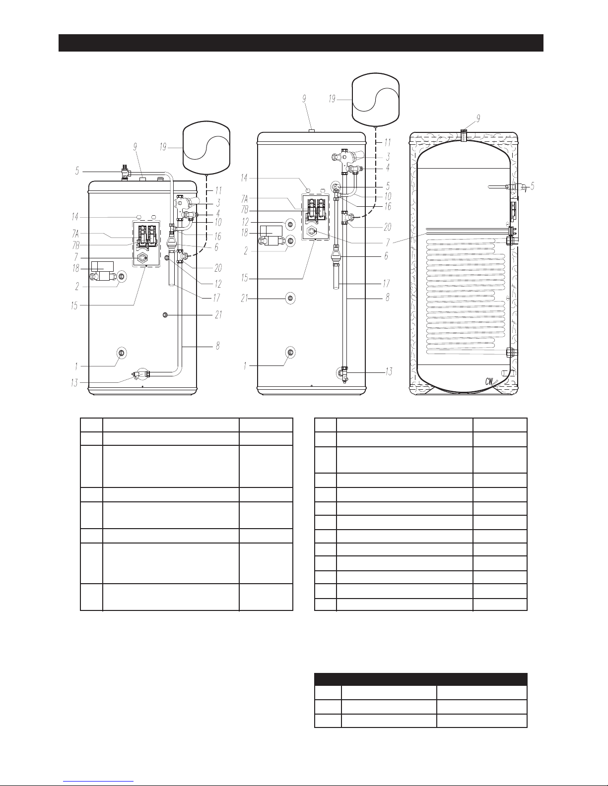
General Layout Fig: 1
1 Return 3/4” BSPF*
2 Flow 3/4” BSPF*
3 Pressure Reducing Valve with 355013
Check Valve and Balanced Cold
Connection
4 Expansion valve 510505
5 Temperature and Pressure
Relief Valve 550853
6 Tundish 219002
7 Immersion Heater 71259
7A Thermostat Immersion Heater 80020
7B Thermostat Heat Pump 80030
8 Cold Feed Tube
(Not supplied - see Table 2)
9 Hot Water Outlet 3/4” BSPF
10 Flexible Hose 202108
11 Flexible Hose for Expansion Vessel
(Not supplied)
12 Sensor Pocket 1/2”
13 Elbow / Drain Cock 250445
14 Cable Entry
15 Electrical Box
16 Tee Piece 250006
17 Discharge Pipe (Not supplied)
18 Motorized Valve M (Not Factory Fitted) 92000
19 Expansion vessel AX 19
20 Tee Piece for Exp. Vessel (Not supplied)
21 Sensor Pocket 1/2”
KEY Part No. KEY Part No.
EXTERNAL VIEW 200 L. EXTERNAL VIEW 250 & 300 L. CUTAWAY VIEW
Size Lenght of tube (ø22) mm Exp. vessel pre charge
200 810 3,5 bar
250 1060 3,5 bar
300 1300 3,5 bar
TABLE 2

- 3 -
1. To obtain the best performance from your OSO unvented system it is advisable to feed the unit
with an uninterrupted supply.
2. Before connecting to the multibloc, ush the cold supply pipework of all ux and debris.
3. Locate the water heater in a suitable position to facilitate the installation of the cold water supply,
discharge ttings and pipework. Also take into account access to the immersion heaters and the
commissioning valve.
4. Fit both 1/2’’ male heat pump sensor pockets to the Sensor Pocket bosses (12&21).
10. Remove the appropriate nuts and rings and connect the exible hose to the expansion relief valve
and the right pointing T-piece connection.
11. If a balanced mains pressure cold water supply is required to a shower or bidet (over rim type
only), remove the blanking cap from the pressure reducing valve (3) and connect to the shower
or bidet cold supply. Do not use the balanced cold connection to feed bath taps as this can reduce
the ow available to the unvented cylinder.
12. Connect the cold supply to the Multibloc (3).
13. Fit the expansion vessel to the wall close to the water heater using the enclosed mounting bracket.
Connect the expansion vessel hose to the T piece in the cold feed pipe to the cylinder.
The expansion vessel is supplied with the OSO unit, t as shown on page 2.
Hot water supply
14. Connect the hot water supply pipe to the outlet (9). Ensure connection is water tight.
Secondary return (optional)
15. Connect secondary return (if required) by tting a T-piece (not supplied) into the cold feed tube (8)
according to diagram on page 16.
Discharge pipe
16. Connect the discharge pipe from the tundish (6). This must have a continuous fall and be tted
in accordance with The Building Regulations (see page 16). The tundish should be installed away
from electrical devices.
Primary ow & return & motorised valve - heat pump
17. The heat pump primary ow and return connections should be made to the unit. The motorised valve
must be tted either on the ow or return of the primary water heating circuit. The primary ow and
return connections are ¾” female. The valve has 22mm copper connections. The direction of the
primary ow in the coil is top to bottom.
200 litre cylinder:
5. Fit the combined male elbow drain cock to
cold supply point (13), so that the compress-
ion tting is horizontal point to the right.
6. Fit the length of copper tube 22mm specied
in table 2 to the cold feed elbow with a right
angle bend as shown to include a T piece for
the expansion vessel.
7. Fit the pressure reducing valve to the top of
the copper tube so that the black knob is
facing right.
8. Fit a 15mm copper tube to the T & P valve
and bend around the top of the cylinder to
pass close and 50 mm to the left of the cold
feed pipe. Cut the pipe off 700 mm from the
oor. Fit the compression end of the T piece
to the bottom of the 15mm copper pipe with
the female end pointing down and the right
angle connection pointing 45° to the right.
9. Remove the nut and ring from the top
connection of the tundish and screw the male
thread into the female thread of the T piece.
250 & 300 litre cylinder:
5. Fit the combined male elbow drain cock to
cold supply point (13), so that the compress-
ion tting is vertical.
6. Fit the length of copper tube 22mm specied
in Table 2 to the cold feed elbow (see 5
above) to include a T piece for the expansion
vessel.
7. Fit the pressure reducing valve to the top of
the copper tube so that the black knob is
facing right.
8. Fit the female outlet of the tee piece to the
temperature and pressure relief valve (5) with
the horizontal connection facing right at
approx. 45°.
9. Fit the tundish to the T piece using a short
length of copper tube.
COLD WATER SUPPLY

- 4 -
Filling up
1. Open a hot tap.
2. Open the cold water supply valve
3. when water ows from hot tap, close the tap
4. Allow the system to stabilize for 5 minutes
5. Open each hot water tap in turn to expel air from the system pipe work.
7. Check for leaks.
8. Manually operate Temperature and Pressure Relief Valve (5) to ensure free water ow through
discharge pipe. (Turn knob to left.)
Draining/ushing
1. Turn off mains supply.
2. Connect hose pipe to drain cock at base of cylinder.
3. Open hot tap. Open drain valve and open temperature & pressure relief valve.
4. Allow to drain. Follow commissioning instructions (above) to rell.
Safety Cut-out
1. The safety cut-out operates if:
a. Wiring is incorrect.
b. The immersion heater thermostat or cylinder thermostat fails.
c. Thermostat is set too high.
2. Remember before resetting the safety cut-out or altering the thermostat setting, isolate electrical
supply to the unit prior to removal of the electrical box lid.
3. Reduce thermostat setting and press the reset button. After adjustments are completed, ensure
the lid to the electrical box is replaced correctly and the retaining screw is tted.
4. If still out of operation, contact installer.
Cold or tepid water discharge from tundish - The tundish should be installed away from electrical devices.
1. Close cold water supply valve
2. Open a hot tap.
3. Repressurise the expansion vessel air charge to its set level.
4. Close hot tap
5. Open the cold water supply valve
Hot water discharge from tundish
This indicates a malfunction of a thermal cut-out, operating thermostat or the combined temperature
and pressure relief valve. Turn off the electrical supply to the immersion heater and also isolate an
indirect unit from the boiler. Contact the installer or competent engineer.
COMMISSIONING
SAFETY AND MAINTENANCE
RECOMMISSIONING INSTRUCTIONS
TABLE 3
Product Max. design Operating pressure
Pressure drop
Temp. / pressure Safety valve Exp. vessel
code pressure CW feed & coil
primary heater
relief valve Pressure / conn. capacity
HP GEO 200 8 bar cw in 3 bar, coil 2.5 bar 0,2 bar 90-95°C / 10 bar 8 bar / 15mm - 1/2” 19 l.
HP GEO 250 8 bar cw in 3 bar, coil 2.5 bar 0,2 bar 90-95°C / 10 bar 8 bar / 15mm - 1/2” 19 l.
HP GEO 300 8 bar cw in 3 bar, coil 2.5 bar 0,2 bar 90-95°C / 10 bar 8 bar / 15mm - 1/2” 19 l.

- 5 -
Positioning the unit
The water heater should be tted level on a hard surface with sufcient load strenght to take the
full weight of the cylinder (see table 1 page 1). Adjustable feet are tted to ensure the unit can be
adjusted to a level position. There is no limitations regarding the tting distance from walls etc., but
it is strongly recommended to ensure easy access to all pipe ttings etc. There should be at least 80
cm of free space in front of the water heater to ensure easy access for servicing and maintenance.
Protection from frost
If the water heater is in danger of being exposed to frost while not operating under electric power,
the unit must be drained to avoid damage. Make sure the electric power is turned off before draining,
otherwise the heating elements can be damaged and the warranty is void. Draining instructions, see
“Commissioning” on page 4.
Cold water inlet control (Multibloc) See Page 2 Items 3 - 4
This combination consists of a pressure reducing valve with integral strainer, check valve and
expansion valve with stainless steel seat. The pressure settings are set and locked in the factory and
are shown on the top of each valve. For optimum performance the following installation instructions
should be complied with.
Installation
1. Cold water supply to be 22mm nominal size.
2. Flush supply pipework before connection to remove all ux and debris prior to tting the inlet
controls. Failure to do this may result in irreparable damage to the controls and will invalidate
the warranty.
3. The “MULTIBLOC” can be tted in any orientation to suit the installation as long as it is tted in
the correct ow direction. Check the ow arrows on the side of the body.
4. The expansion valve should be either horizontal or pointing downwards. If tted upwards, debris
may be deposited on the seat and cause fouling of the seat when the valve operates. Check
direction of ow arrows.
5. The black plastic plugs in the body are pressure gauge connections to enable pressure
monitoring to be carried out, should the system develop a fault. It is recommended that these
be accessible (the pressure reducing valve has two - only one need be accessible).
6. Expansion relief drain pipework must be connected to a safe visible discharge point via a
tundish and the pipework must have a continuous fall.
7. The pressure reducing valve has two outlets, the second one is for a balanced cold water
supply, to a shower or a bidet (over rim type only, ascending spray type requires type AA,
ABorADairgap).(Majorshowermanufacturersadvisettingaminiexpansionvesselin
thebalancedcoldsupplytoaccommodatethermalexpansionandpreventtighteningof
shower controls).
Using the balanced cold connection to feed bath taps can reduce the ow available to the
unvented cylinder. If not required the balanced cold supply is blanked off.
The Benchmark Log Book enclosed with the cylinder should be completed after commissioning
of the system and handed to the customer for future use.
INSTALLATION AND SERVICING INSTRUCTIONS
TABLE 4
Product Actual Weight Weight Heat-up (mins) Rating (kW) Heat loss Primary Hot Water
code capacity(l.) empty full coil coil kWh/24h owrate Capacity
HP GEO 200 197 50 241 20,8 26,9 1,9 15 l/min. - 80°C 179
HP GEO 250 245 55 292 23 29,7 2,1 15 l/min. - 80°C 209
HP GEO 300 286 65 341 27 27,1 2,3 15 l/min. - 80°C 237
 Loading...