

OSO Dualstream Installation Manual

TECHNICAL AND INSTALLATION MANUAL
HOT WATER
CAPACITY
120 - 380 LITRES
BY
OSO HOTWATER (UK) LIMITED
This manual gives detailed advice for installation and should be read
carefully prior to fitting the OSO Dualstream. Where components are
supplied only for indirect units, this is clearly shown.
The OSO Dualstream must be installed by a competent person and in
accordance with current Building Regulations including Guidance
Document G3.
Drawings on pages 1-18 show
22mm valves on cold water supply.
For 28mm see page 19.
IM/OD/1

1
CONTENTS
INTRODUCTION 1
1-1 Introduction .......................................................... 2
1-1.1 How the OSO Dualstream System Works
. 2
1-1.2 System Contains
.................................................. 2
1-1.3 System Features
.................................................. 2
1-1.4 Central Heating System
.................................... 3
1-1.5 Models Available
.................................................. 3
OPERATOR CONTROLS 2
2-1 Hot Water Temp. ............................................... 4
2-1.1 Hot Water Control - Heating System
.......... 4
2-1.2 Hot Water Control - Immersion Heater
...... 4
2-2 Hot Water Overheating
................................... 6
2-2.1 Water Heated by Heating System
................ 6
2-2.2 Water Heated by Immersion Heater
............ 6
2-3 Shut Off Valves
................................................... 6
2-3.1 Stop Cock
................................................................ 7
2-3.2 Double Check Valve
........................................... 7
2-3.3 Cold Water Shut Off Valve
............................... 7
2-3.4 Supply Water Shut Off Valve
.......................... 7
2-3.5 Hot Water Shut Off Valve
................................. 7
2-4 Pressure Relief
................................................... 7
2-5 Servicing
................................................................ 7
TECHNICAL INFORMATION 3
3-1 System Components....................................... 8
3-2 Specifications
...................................................... 8
3-2.1 Cylinder
.................................................................... 8
3-2.2 Accumulator
.......................................................... 8
3-2.3 Pipes
.......................................................................... 8
3-2.4 Electrics
.................................................................... 8
3-3 Wiring
....................................................................... 9
3-3.1 Immersion Heater
................................................ 9
3-3.2 Wiring Layout S Plan
.........................................10
3-3.3 Wiring Layout Y Plan
..........................................11
INSTALLATION 4
4-1 Building Control ................................................12
4-1.1 Regulations
............................................................12
4-1.2 Electrical Regulations
........................................12
4-2 Installation
............................................................12
4-2.1 Positioning
..............................................................12
4-2.2 Unvented Hot Water Cylinder
........................12
4-2.3 Accumulator
...........................................................13
4-2.4 Tundish
.....................................................................13
4-2.5 Discharge Pipe
.....................................................13
4-2.6 Scale Protection
...................................................14
4-2.7 Pipework
..................................................................14
4-2.8 OSO Dualstream Components
.....................14
4-2.9 Connections to OSO Dualstream
.................14
4-3.0 Direct Cylinders
....................................................14
COMMISSIONING 5
5-1 Commissioning Checks................................15
5-1.1 Commissioning Procedure
..............................15
5-2 Handing Over
......................................................15
SERVICING 6
6-1 Routine Service..................................................16
6-1.1 Service Procedure
...............................................16
SPARE PARTS 7
7-1 Spare Parts...........................................................17
SECONDARY RETURN 8
8-1 Secondary Return.............................................17
OSO DUALSTREAM 9
9-1 OSO Dualstream................................................18
CONNECTIONS 10
10-1 28mm Connections..........................................19
FAULT DIAGNOSIS 11
11-1 Fault Diagnosis ..................................................19

1-1 INTRODUCTION
This Handbook has been compiled to assist in the Installation and Operation of the OSO Dualstream domestic hot and cold
water system. The Installer of the system should give full operating instructions to the householder for the OSO Dualstream
System.
1-1.1 How the OSO Dualstream system works
Fig.1-1 is a schematic illustration of a typical OSO Dualstream system showing how it works.
Option A is used when the accumulator is installed remotely from the unvented cylinder and requires an accessory pack
containing pressure reducing valve, expansion relief valve expansion vessel and bracket, available at additional cost and
should be ordered with the system.
1-1.2 System Contains
1. An unvented hot water cylinder pre-plumbed with all valves and controls with easy access pipe connections for quick,
trouble-free installation.
2. Cylinder Thermostat and High Limit Thermostat.
3. An Accumulator (cold water storage) and associated fittings.
4. One two port motorised valve for connection to heating system flow to cylinder (Indirect only).
5. The OSO Dualstream is supplied with an adjustable pressure reducing valve. This means pressure to all mains water
outlets can be adjusted between 0.5 bar to 5 bar.
1-1.3 System Features
1. All Taps and Showers are at maximum ‘Mains Pressure’.
2. Equal pressure at Hot and Cold Taps.
3. No pressure drop when more than one Tap is in use.
4. More than 25% less pipework than traditional systems.
5. No loft storage tank.
6. Completely sealed system - all Cold Taps are classed as wholesome water.
2
INTRODUCTION 1
Fig. 1-1 Schematic illustration
(Indirect unit)
Rubber expanding
bladder inside vessel.
Pressure is maintained
at maximum
‘Mains Pressure’.
Pressure relief valve
vents excess pressure
from Hot Water System.
Hot Water Cylinder is at
‘Mains Pressure’ due to
incoming cold.
Cylinder with immersion
heater. Water can be heated
by any conventional method.
Existing
Mains Supply
Hot Supply
Option A
Non-return valve. As
water is used system
is equalised to
maximum ‘Mains
Pressure’.
Boiler Return
Secondary Return
Boiler Flow
Air Pressure
Diaphragm
Accumulator
Mains Water
3
INTRODUCTION 1
1-1.4 Central Heating System
The OSO Dualstream system does not affect the Central Heating installation. However consideration has to be
given to the best method of connection and control of the heating system to the indirect cylinder.
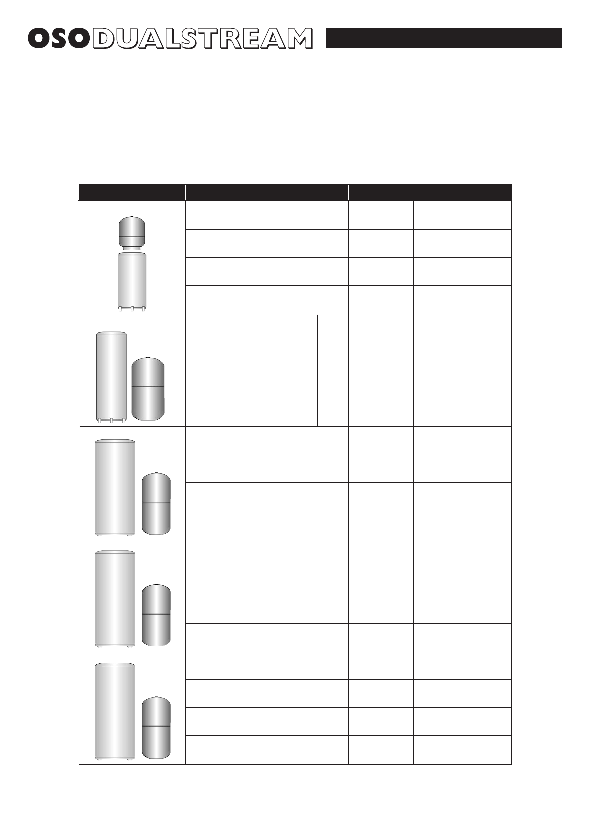
1-1.5 Models Available
Below is a typical selection of the systems available, other combinations can be tailored to suit requirements.
Model Accumulator (Cold Water Storage)
Weight Full (Kg)
Hot Water
Storage Capacity
(L)
Cylinder
Type
Hot Water Cylinder (Direct RD Indirect RI)
20 R
120
120
160
580
720
All sizes are nominal
Very low mains flow rates may require larger or multiple accumulators
Weight Full (Kg)
Diameter
Height
Diameter
Height
Nominal Capacity
(L)
Vessel
Type
19608
100
86
440
890
Weight Full (Kg)
Hot Water
Storage Capacity
(L)
Cylinder
Type
20 R
120
120
160
580
720
20 R
150
150
190
580
900
20 R
200
200
250
580
1150
Weight Full (Kg)
Diameter
Height
Diameter
Height
Nominal Capacity
(L)
Vessel
Type
18891
170
150
535
995
Weight Full (Kg)
Hot Water
Storage Capacity
(L)
Cylinder
Type
20 R
200
200
250
580
1150
20 R F1
200
250
310
580
1400
Weight Full (Kg)
Diameter
Height
Diameter
Height
Nominal Capacity
(L)
Vessel
Type
18892
240
205
540
1220
Weight Full (Kg)
Hot Water
Storage Capacity
(L)
Cylinder
Type
20 R F1
250
250
310
580
1400
20 R F1
300
300
365
580
1600
Weight Full (Kg)
Diameter
Height
Diameter
Height
Nominal Capacity
(L)
Vessel
Type
18893
310
255
540
1500
Weight Full (Kg)
Hot Water
Storage Capacity
(L)
Cylinder
Type
20 R F1
300
300
365
580
1600
20 R F1
380
380
462
580
2100
Weight Full (Kg)
Diameter
Height
Diameter
Height
Nominal Capacity
(L)
Vessel
Type
18894
450
385
665
1550

2-1 HOT WATER TEMPERATURE
2-1.1 Hot Water Control - Heating System (Indirect only)
When the hot water is heated by the heating system the temperature of the hot water at the taps is controlled by the Cylinder Thermostat.
This controls a Motorised Valve that opens and closes the flow from the heating system.
The temperature range is 45°C to 75°C.
Recommended setting is between 50°C minimum and 70°C maximum.
1 Indirect Units
Motorised valve
To comply with regulations governing the installation of indirect unvented
cylinders, a motorised valve must be fitted in the primary flow. Your OSO unit has
been supplied with a two port motorised valve, which will act as a positive energy
cut-out should the safety cut-out operate. The motorised valve will also control the
temperature of the domestic stored water via the cylinder thermostat, which is
located in the electrical box. The unit should be installed on an “S’’ or “Y’’ plan
system. Please follow the instructions carefully. All electrical connections must
conform to current IEE wiring regulations. The working thermostat which controls
the temperature of the domestic hot water (see fig. 2) is adjustable between 45°C
to 75°C. A safety cut out is also incorporated within the thermostat and will
operate at 85°C ± 3°C. Should the safety cut out be brought into operation, the
motorised valve will operate and close down the primary flow to the cylinder. To
reset the safety cut out and the motorised valve the reset button must be pressed
in (see fig. 2). If using a 6-wire 28mm or 1’’ BSP V4043H on either circuit the white
wire is not needed and must be made electrically safe.
2-1.2 Hot Water Control - Immersion Heater
When the hot water is heated by the electric Immersion Heater, the temperature
of the hot water at the taps is controlled by the Immersion Heater Thermostat.
This is located under the electrical box cover, left hand thermostat.
2 Direct units
Wiring instructions for the water heaters are located on the reverse side of the lid.
Follow the wiring instructions connecting the live, neutral and earth as
indicated. All internal wiring is factory mounted. Each immersion heater has
a working thermostat adjustable between 45°C to 75°C. A safety cut-out is
also incorporated within the thermostat and will operate at 85°C ± 3°C.
Should this happen, press the reset button.
Important: Before resetting the safety cut-out or altering the thermostat
setting, isolate electrical supply to the unit prior to removal of the lid.
Ensure the lid to the electrical box is replaced correctly and the
retaining screw is fitted.
The lower immersion heater should be connected to the off peak supply
(if available) whilst the top immersion heater can be connected to the day
tariff. The immersion heater can be connected to the mains supply through a
water heater controller (Contact your local electricity company if in doubt).
WARNING: When the cover is removed electrical live terminals are
exposed.
ALWAYS TURN OFF THE ‘WATER HEATER’ SWITCH BEFORE
REMOVING COVER.
The temperature range is 45°C to 75°C.
Recommended setting is between 50°C minimum and 70°C maximum.
The electrical connection to the immersion heater must conform to
current IEE wiring regulations. The unit must be permanently connected
to the electrical supply through a double-pole linked switch with a
minimum break capacity of 13 amps.
4
OPERATOR CONTROLS 2
Fig. 2-1a Hot Water Control
Fig. 2-1b Immersion Heater Thermostat
Return to Boiler
Motorised valve
Flow from Boiler
Pole Switch
LN
Adjustment
Screw

5
OPERATOR CONTROLS 2
IMPORTANT HEALTH AND SAFETY INFORMATION FOR INSTALLERS AND SERVICE ENGINEERS
HEALTH AND SAFETY AT WORK ACT 1974
CONSUMER PROTECTION ACT 1987
COSHH REGULATIONS 1988
MANUAL HANDLING OPERATIONS REGULATIONS 1992
The regulations set no specific requirements such as weight limits. However common sense still has to be used
based on an ergonomic approach for each individual.
The following information is given as a requirement of the above legislation.
Great care is taken to ensure that OSO Dualstream systems are designed and manufactured to meet general
safety requirements when properly used and installed as recommended in this manual.
It is the responsibility of Users and Engineers to ensure that adequate protective clothing and glasses are worn
when working with the OSO Dualstream system.
SEALS AND INSULATION
Insulation and sealing materials are used in the construction of the OSO Dualstream cylinders. Units are sealed
and when used in the manner for which they are intended the insulating and sealing materials do not present any
known hazard. However always observe the following recommendations:-
1. Avoid inhalation of fibres or dust, wear face mask.
2. Avoid eye contamination by fibres or dust – wear eye protection.
3. As far as possible avoid any skin contact with Fibreglass Insulation, Glass Rope, Mineral Wool, Insulation
Pads and Ceramic Fibre.
OTHER MATERIALS
SEALANTS, ADHESIVES AND PAINTS
Sealants, Adhesives and Paints are used in the construction of the OSO Dualstream components. When used in
the manner for which they are intended they do not present any known hazard.
ELECTRIC
All Cylinders have electrical supply of 240v (enough to endanger life) connected to the Immersion Heater. Always
isolate during adjustment, servicing and repair.
OSO (UK) will not accept responsibility for any damage or personal injury caused by not giving due
consideration to the above safety recommendations.
All replacement parts must be supplied by OSO HOTWATER (UK) LIMITED.
To obtain the address of a local stockist contact:
OSO HOTWATER (UK) LIMITED
E15 Marquis Court, Team Valley Trading Estate, Gateshead, Tyne & Wear, NE11 0RU.
Tel: (0191) 482 0800 Fax: (0191) 491 3655
Email : technical.uk@oso-hotwater.com - spareparts.uk@oso-hotwater.com - sales.uk@oso-hotwater.com
www.oso-hotwater.com
 Loading...