

OSO 20 RD, 20 RI Installation Manual
20 RD
20 RI
IM/5a
Installation details
The OSO unvented unit is designed for use with supply pressure up to 16 bar. For pressures over
16 bar an additional pressure reducing valve must be fitted in the supply pipe to the unit.
Wall mounting brackets are available for OSO unvented units 100-170 litres capacity.
Components supplied with the unit for site fitting
(See also page 2 for component list)
*
Multibloc valve, includes pressure reducing valve, line strainer, balanced cold water take off,
(for shower or bidet only) check and expansion valve.
*
Tundish
*
1/2''F x 15 x 15 tee piece.
*
Flexible hose.
*
3/4'' x 22mm Elbow / Drain Cock.
*
Commissioning valve, 1/2'' BSP male.
*
Motorised valve (indirect only).
Components factory fitted
*
Immersion heater(s).
*
Thermostats / thermal cut-out.
*
Temperature and pressure relief valve.
This manual gives detailed advice for installation and should be read carefully
prior to fitting any unvented unit. Where components are supplied only for
indirect units, this is clearly shown.
This OSO cylinder must be installed by a competent person and be installed in
compliance with the OSO Installation and Maintenance Instructions, all current
legislation, codes of practice and regulations governing the installation of
unvented hot water cylinders in force at the date of installation.
-1-
PLEASE LEAVE THIS MANUAL WITH THE OSO UNIT AFTER INSTALLATION
INSTALLATION MANUAL
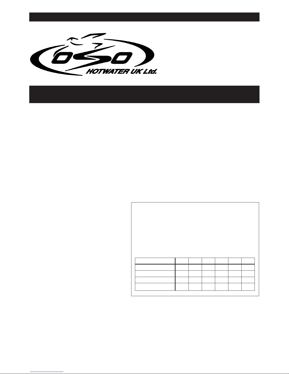
PRODUCT REF.
HEIGHT
DIAMETER
WEIGHT EMPTY
MAX WEIGHT FULL
100
720
580
34
132
900
580
40
163
115 0
580
48
215
125 170
1400
580
60
261
210
1600
580
64
303
250
2090
580
82
397
330
DIMENSION AND WEIGHTS TABLE 1
00142040-06 IM/5
Health and Safety
Manual Handling Operations Regulations 1992 defines manual
handling as: “any transporting or supporting of a load (including the
lifting, putting down, pushing, pulling, carrying or moving thereof) by
hand or bodily force”. The Regulations set no specific requirements
such as weight limits. However common sense still has to be used
based on an ergonomic approach for each individual.
20S (IM) 16pp ISSUE 8
-2-
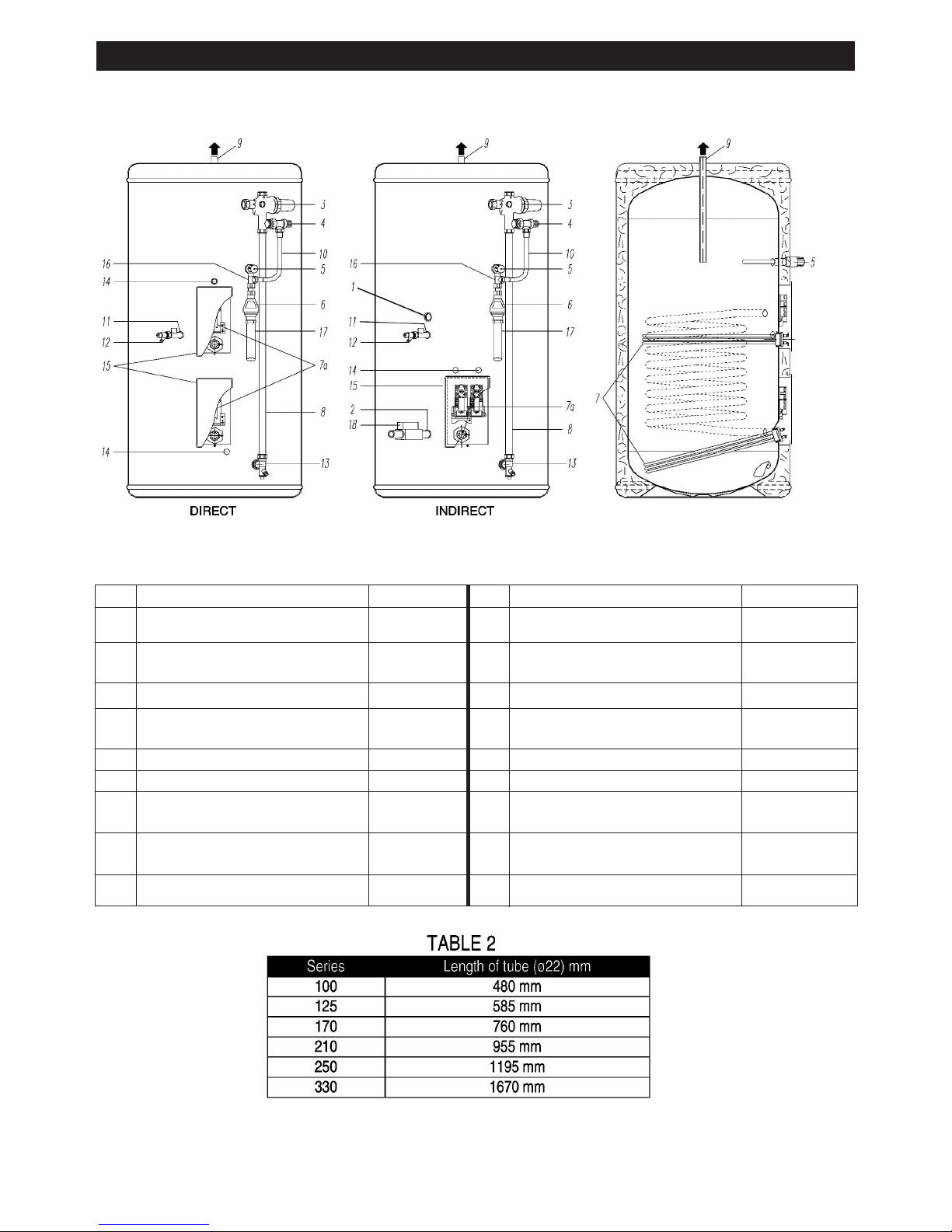
General Layout Fig:1
1
2
3
4
5
6
7
7A
8
9
Return 3/4'' BSPF
*
Flow 3/4'' BSPF*
Pressure Reducing Valve
includes item 4
Check and Expansion Valve
Temperature and Pressure
Relief Valve
Tundish
Immersion Heater
Thermostat Immersion Heater
Thermostat Cylinder
Cold Feed Tube
(Not Supplied See Table 2)
Hot Water Outlet 22mm
510511
510505
550803
219002
71259
80020
80030
10
11
12
13
14
15
16
17
18
*
Flexible Hose
Secondary Return 1/2'' BSPF
Fit 1/2''Fx1/2''Mx15mm Tee piece (Not supplied)
Commissioning Valve / Fitting
1/2'' MI Drain Cock
Elbow / Drain Cock
Cable Entry
Electrical Box
Tee Piece
Discharge Pipe (Not supplied)
Motorised Valve * (Not Factory Fitted)
Indirect Only
202108
250440
250445
250006
92000
KEY Part No KEY Part No

1. To obtain the best performance from your OSO unvented system it is advisable to feed the unit
with an uninterrupted supply.
2. Locate the water heater in a suitable position to facilitate the installation of the cold water supply,
discharge fittings and pipework. Also take into account access to the immersion heaters and the
commissioning valve.
3. Fit the combined male elbow / drain cock to cold supply point (13), so that the compression
fitting is vertical.
4. Fit the commissioning valve (12) to the commissioning fitting.
5. Fit the female outlet of the tee piece to the temperature and pressure relief valve (5) with the
horizontal connection facing right at approx. 45°.
6. Fit the tundish (6) to the tee piece using a short length of 15mm copper tube.
7. Fit the length of copper tube 22mm specified in Table 2 to the cold feed elbow (see 3 above).
8. Fit the pressure reducing valve(3) to the top of the copper tube (see 7 above), so that the black
knob is facing right.
9. Connect the flexible hose to the 1/2'' outlet of the expansion valve (4) and the horizontal outlet
of the tee piece (see 5 above). Discard compression nut & ring.
10. If a balanced mains pressure cold water supply is required to a shower or bidet (over rim type
only, ascending spray type requires type AA,AB or AD air gap), remove the blanking cap
from the pressure reducing valve (3) and connect to the shower or bidet cold supply. (Major
shower manufacturers advise fitting a mini expansion vessel in the balanced cold supply
pipework to accommodate thermal expansion and prevent tightening of shower controls)
Using the balanced cold connection to feed outlets that do not require a balanced cold
supply can reduce the flow available to the unvented cylinder.
11. Before connecting the cold supply, flush the cold supply pipework of all flux and debris.
12. Connect the cold supply to the pressure reduction valve (Multibloc) (3).
Hot water supply
13. Connect the hot water supply pipe to the outlet (9). Ensure connection is water tight.
Secondary return
14. A secondary return facility is provided on all units. Fit a 1/2''F x 1/2''M x 15mm tee piece between
the commissioning valve (12) and the commissioning fitting. See also figure 5 on page16.
Discharge pipe
15. Connect the discharge pipe from the tundish (6). This must have a continuous fall and be fitted
in accordance with The Building Regulations (see pages 5 and 12).
Primary flow & return and motorised valve (Indirect only)
16. The boiler primary flow and return connections should be made to the unit and include a by-pass
with automatic by-pass valve. The motorised valve must be fitted into the primary heating circuit.
17. For electrical connection of the motorised valve and immersion heater, please read Electrical
Installation Instructions. (Pages 7 - 11)
COLD WATER SUPPLY
-3-

Filling up
1. Close all hot water taps.
2. Open the commissioning valve (12).
3. Open the cold water supply valve.
4. When water flows from the commissioning valve (12), close the valve and continue to fill.
5. Allow system to stabilise for five minutes.
6. Open each hot water tap in turn to expel air from the system pipe work.
7. Check for leaks.
8. Manually operate Temperature and Pressure Relief Valve (5) to ensure free water flow through
discharge pipe. (Turn knob to left.)
Draining
Switch the electrical power off (important to avoid damage to element). Isolate boiler from OSO unit.
Turn off the cold water supply valve. Open hot water tap. Open drain (13). The unit will drain.
Safety Cut-out
1. The safety cut-out operates if:
a. Wiring is incorrect.
b. The immersion heater thermostat or cylinder thermostat fails.
c. Thermostat is set too high.
2. Remember before resetting the safety cut-out or altering the thermostat setting, isolate electrical
supply to the unit prior to removal of the electrical box lid.
3. Reduce thermostat setting and press the reset button. After adjustments are completed, ensure
the lid to the electrical box is replaced correctly and the retaining screw is fitted.
4. If still out of operation, contact installer.
Cold or tepid water
discharge from tundish
1. Turn off the electrical supply to the immersion heaters.
2. Turn off cold water supply valve.
3. Open a hot tap.
4. Drain water from commissioning valve (12) until water flow stops.
5. Turn the knob on the Temperature and Pressure Relief Valve (5) to the left and hold in this
position until water flow stops from the commissioning valve.
6. Close commissioning valve.
7. Close all hot taps.
8. Open cold water supply valve.
9. Turn on electrical supply to the immersion heaters.
COMMISSIONING
SAFETY AND MAINTENANCE
-4-

Hot water discharge from tundish
This indicates a malfunction of a thermal cut-out, operating thermostat or the combined temperature
and pressure relief valve. Turn off the electrical supply to the immersion heater and also isolate an
indirect unit from the boiler. Contact the installer or competent engineer.
Cold water inlet control (Multibloc) See Page 2 Items 3 - 4
This combination consists of a pressure reducing valve with integral strainer, check valve and
expansion valve with stainless steel seat. The pressure settings are set and locked in the factory and
are shown on the top of each valve. For optimum performance the following installation instructions
should be complied with.
Installation
1. Cold water supply to be 22mm nominal size.
2. Flush supply pipework before connection to remove all flux and debris prior to fitting the inlet
controls. Failure to do this may result in irreparable damage to the controls and will invalidate
the warranty.
3. The “MULTIBLOC” can be fitted in any orientation to suit the installations as long as it is fitted
in the correct flow direction. Check the flow arrows on the side of the body.
4. The expansion valve should be either horizontal or upright - if fitted inverted, debris may be
deposited on the seat and cause fouling of the seat when the valve operates. Check direction
of flow arrows.
5. The black plastic plugs in the body are pressure gauge connections to enable pressure
monitoring to be carried out, should the system develop a fault. It is recommended that these
be accessible (the pressure reducing valve has two - only one need be accessible).
6. Expansion relief drain pipework must be connected to a safe visible discharge point via a
tundish and the pipework must have a continuous fall.
7. The pressure reducing valve has two outlets, the second one is for a balanced cold water
supply, to a shower or a bidet (over rim type only, ascending spray type requires type AA,
AB or AD air gap) (Major shower manufacturers advise fitting a mini expansion vessel in
the balanced cold supply pipework to accommodate thermal expansion and prevent
tightening of shower controls). Using the balanced cold connection to feed outlets that
do not require a balanced cold supply can reduce the flow available to the unvented
cylinder. The balanced cold supply is blanked off.
8. If an expansion vessel is to be fitted it must be connected to the cold feed pipe between the
pressure reduction valve, (Multibloc) (3) and the cylinder.
NOTE: If the unit has been commissioned and is to be unused for more than 8 weeks it is
advisable to turn off the cold supply and draw off approximately 5 litres of water through a hot
tap. NB The cold supply must be opened prior to use.
The Benchmark Log Book enclosed with the cylinder must be completed after
commissioning the system and handed to the customer for future reference.
INSTALLATION AND SERVICING INSTRUCTIONS
-5-
 Loading...