

OSNA NMH, NMH 65, NMH 80, NMV 32, NMV 40 Operating Manual
...
Ver.17-02
Original Operating Manual
NMH/NMV High-Pressure
Centrifugal Pump
OSNA-Pumpen GmbH
Brückenstrasse 3
49090 Osnabrück, Germany
Phone: +49 541 1211 - 0
Fax: +49 541 1211 - 220
Internet: http://www.osna.de
E-mail: info@osna.de


NMH/NMV High Pressure Centrifugal Pump 1
Contents
1 GENERAL ........................................................................................................................................ 6
1.1 About this operating manual .................................................................................................... 6
1.2 Target groups .......................................................................................................................... 6
1.3 Other valid documents ............................................................................................................. 6
1.4 Warning notices and symbols .................................................................................................. 7
1.5 Copyright/changes ................................................................................................................... 7
2 SAFETY ........................................................................................................................................... 8
2.1 Correct and proper use ............................................................................................................ 8
2.2 General safety instructions ...................................................................................................... 9
2.2.1 Product safety ...................................................................................................................... 9
2.2.2 Duties of the system owner ................................................................................................. 9
2.2.3 Duties of personnel ............................................................................................................ 10
2.3 Dangers of non-observance of the safety instructions .......................................................... 11
2.4 Unauthorized conversion and production of spare parts ....................................................... 11
2.5 Unauthorized modes of operation ......................................................................................... 11
2.6 Special hazards ..................................................................................................................... 11
2.6.1 Explosion area ................................................................................................................... 11
2.6.2 Hazardous pumping media ................................................................................................ 11
2.6.3 Noise emissions................................................................................................................. 12
3 LAYOUT AND FUNCTION ............................................................................................................ 13
3.1 Labeling ................................................................................................................................. 13
3.1.1 Pump type labeling ............................................................................................................ 13
3.1.2 Type plate .......................................................................................................................... 13
3.2 Scope of delivery of an NMH/NMV high-pressure centrifugal pump ..................................... 14
3.3 General information ............................................................................................................... 14
3.4 Technical data ....................................................................................................................... 15
3.5 Operating point ...................................................................................................................... 15
3.6 Minimum output rates ............................................................................................................ 15
3.7 Functional and operating elements ....................................................................................... 16
3.8 Auxiliary operating systems ................................................................................................... 16
4 TRANSPORT AND INTERMEDIATE STORAGE ......................................................................... 18
4.1 Transport ............................................................................................................................... 18
4.1.1 Unpacking and checking the delivery condition ................................................................ 18
4.1.2 Lifting ................................................................................................................................. 18
4.2 Intermediate storage .............................................................................................................. 19
4.3 Storage .................................................................................................................................. 19
4.4 Disposal ................................................................................................................................. 20

2 NMH/NMV High Pressure Centrifugal Pump
5 ASSEMBLY AND INSTALLATION ............................................................................................... 21
5.1 Preparing for installation ........................................................................................................ 21
5.1.1 Preparing the installation location...................................................................................... 21
5.1.2 Preparing the base surface and foundations ..................................................................... 21
5.1.3 Removing the preservative ................................................................................................ 22
5.2 Installation .............................................................................................................................. 23
5.2.1 Installing the pump ............................................................................................................ 23
5.2.2 Securing the pump unit ...................................................................................................... 25
5.2.3 Assembling the motor ........................................................................................................ 25
5.3 Fine alignment of the coupling ............................................................................................... 26
5.3.1 Horizontal configuration ..................................................................................................... 26
5.3.2 Vertical configuration ......................................................................................................... 27
5.4 Aligning the motor .................................................................................................................. 28
5.4.1 Aligning the motor with shims ............................................................................................ 28
5.4.2 Aligning the motor with adjustment screws ....................................................................... 28
5.5 Planning pipelines ................................................................................................................. 29
5.5.1 General .............................................................................................................................. 29
5.5.2 Avoiding contaminations in the pipelines .......................................................................... 31
5.5.3 Configuring supports and flange connections ................................................................... 31
5.5.4 Determining nominal widths .............................................................................................. 31
5.5.5 Determining pipeline lengths ............................................................................................. 31
5.5.6 Optimizing changes in cross-section and direction ........................................................... 32
5.5.7 Providing safety and monitoring systems (recommended) ............................................... 32
5.6 Attaching the pipelines .......................................................................................................... 32
5.6.1 Installing auxiliary pipelines ............................................................................................... 32
5.6.2 Installing the suction pipe .................................................................................................. 33
5.6.3 Installing the pressure pipe ................................................................................................ 33
5.6.4 Checking for lack of tension in the pipeline connection .................................................... 33
5.7 Electrical connection .............................................................................................................. 34
5.7.1 Connecting the motor ........................................................................................................ 34
5.7.2 Earthing the pump ............................................................................................................. 35
6 COMMISSIONING/ DECOMMISSIONING .................................................................................... 36
6.1 Commissioning ...................................................................................................................... 36
6.1.1 Determining the pump configuration.................................................................................. 36
6.1.2 Filling the pump ................................................................................................................. 36
6.1.3 Checking direction of rotation ............................................................................................ 37
6.1.4 Starting the pump .............................................................................................................. 38
6.2 Decommissioning .................................................................................................................. 39
6.2.1 Switching off the pump ...................................................................................................... 41
6.2.2 Draining the pump and protecting against frost ................................................................. 41
6.3 Recommissioning .................................................................................................................. 41

NMH/NMV High Pressure Centrifugal Pump 3
6.4 Operating the stand-by pump ................................................................................................ 41
6.5 Shaft seal ............................................................................................................................... 42
6.5.1 Mechanical seal ................................................................................................................. 42
6.5.2 Gland packing .................................................................................................................... 42
7 MAINTENANCE AND REPAIR ..................................................................................................... 43
7.1 General information ............................................................................................................... 43
7.2 Operational monitoring .......................................................................................................... 44
7.3 Maintenance .......................................................................................................................... 45
7.3.1 Anti-friction bearings and grease lubrication ..................................................................... 46
7.3.2 Servicing the electric motors ............................................................................................. 46
7.3.3 Servicing the mechanical seals ......................................................................................... 47
7.3.4 Servicing the gland packing ............................................................................................... 47
7.4 Sending the pump to the manufacturer ................................................................................. 48
7.5 Disassembling the pump ....................................................................................................... 49
7.6 Ordering spare parts .............................................................................................................. 51
8 FAULTS AND TROUBLESHOOTING ........................................................................................... 52
9 APPENDIX ..................................................................................................................................... 55
9.1 Additional ATEX instructions ................................................................................................. 55
9.1.1 Safety ................................................................................................................................. 55
9.1.2 Explosion protection marking ............................................................................................ 56
9.1.3 Installation and connection ................................................................................................ 57
9.1.4 Operation ........................................................................................................................... 59
9.1.5 Maintenance and repair ..................................................................................................... 59
9.2 Spare parts list for constant operation over two years as per DIN 24296 ............................. 60
9.3 Cross-sections ....................................................................................................................... 61
9.4 Declaration of Conformity as per EC Directive 2006/42/EC, Annex IIA ................................ 67
9.5 Declaration of Conformity as per EC Directive 2014/34/EC, Annex VI ................................. 68
9.6 Clearance Certificate ............................................................................................................. 69

4 NMH/NMV High Pressure Centrifugal Pump
List of Tables
Table 1: Target groups and their tasks .................................................................................................... 6
Table 2: Other valid documents and their purposes .............................................................................. 6
Table 3: Warning notices and consequences of non-observance ......................................................... 7
Table 4: Symbols and their meanings ..................................................................................................... 7
Table 5: Sound pressure level ............................................................................................................... 12
Table 6: Main parameters at 1450 rpm ................................................................................................. 15
Table 7: Main parameters at 2900 rpm ................................................................................................. 15
Table 8: Pump series' flange sizes ........................................................................................................ 15
Table 9: Minimum output rates with closed shut-off valve ................................................................... 15
Table 10: Maximum authorized operating temperature at the shaft seal .............................................. 16
Table 11: Ambient conditions ................................................................................................................ 21
Table 12: Settings for the time relay when using three-phase motors with star-delta switch ............... 35
Table 13: Measures depending on the behavior of the pumping medium ........................................... 40
Table 14: Measures in the event of operational interruption ................................................................ 40
Table 15: Measures following longer shut down times ......................................................................... 41
Table 16: Stuffing box dimensions ........................................................................................................ 48
Table 17: Measures for return ............................................................................................................... 49
Table 18: Fault/number allocation ......................................................................................................... 52
Table 19: Troubleshooting table ............................................................................................................ 54
Table 20: Temperature classes ............................................................................................................. 56
Table 21: Ignition protection classes ..................................................................................................... 56
Table 22: Ex atmosphere ...................................................................................................................... 57
Table 23: Equipment groups/areas of use/zone/category ..................................................................... 57
Table 24: Possible devices for monitoring self-warming due to dry running ......................................... 58
Table 25: Measures against unauthorized self-warming ....................................................................... 58
Table 26: Max. pumping medium temperature...................................................................................... 59
Table 27: Spare parts for constant operation over two years ............................................................... 60
Table 28: NMH parts list ........................................................................................................................ 63
Table 29: NMV parts list ........................................................................................................................ 66

NMH/NMV High Pressure Centrifugal Pump 5
List of Images
Figure 1: Model code ............................................................................................................................. 13
Figure 2: Standard version type plate ................................................................................................... 13
Figure 3: ATEX version type plate ......................................................................................................... 13
Figure 4: Scope of delivery for NMH with free shaft .............................................................................. 14
Figure 5: Scope of delivery for NMV without motor ............................................................................... 14
Figure 6: Scope of delivery for NMH as complete unit .......................................................................... 14
Figure 7: Scope of delivery for NMV as complete unit .......................................................................... 14
Figure 8: Gland packing ........................................................................................................................ 16
Figure 9: Mechanical seal ...................................................................................................................... 16
Figure 10: Pressure-side external flushing connection (optional) ........................................................ 17
Figure 11: Suction-side external flushing connection (optional)........................................................... 17
Figure 12: Lifting an NMH centrifugal pump (unit) ................................................................................ 18
Figure 13: Lifting an NMH centrifugal pump (free shaft end) ............................................................... 19
Figure 14: Lifting an NMV centrifugal pump .......................................................................................... 19
Figure 15: Mounting material for complete units ................................................................................... 23
Figure 16: Mounting material for pump with open shaft end ................................................................ 23
Figure 17: Aligning the base plate ......................................................................................................... 24
Figure 18: Positional alignment of the shafts ........................................................................................ 26
Figure 19: Directional alignment of the shafts ....................................................................................... 26
Figure 20: Aligning the motor with adjustment screws .......................................................................... 28
Figure 21: Functional and operating elements ...................................................................................... 29
Figure 22: Recommended straight pipeline lengths upstream and downstream of the pump .............. 31
Figure 23: NMH earthing screws ........................................................................................................... 35
Figure 24: NMV earthing screws ........................................................................................................... 35
Figure 25: Pressure-side stuffing box (standard) .................................................................................. 48
Figure 26: Suction-side stuffing box (standard) .................................................................................... 48
Figure 27: Cross-section of NMH with mechanical seal ........................................................................ 61
Figure 28: Cross-section of NMH with gland packing ........................................................................... 62
Figure 29: Cross-section of NMV with mechanical seal ........................................................................ 64
Figure 30: Cross-section of NMV with gland packing ........................................................................... 65
1 General
6 NMH/NMV High Pressure Centrifugal Pump
1 General
1.1 About this operating manual
This operating manual contains important instructions that must be observed during installation, operation and maintenance. For this
reason, ensure that it is read by specialist personnel and the responsible operator/owner
prior to assembly and commissioning. The
manual must be available at all times at the
location where the system is used.
Please observe the safety instructions described in this operating manual, along with the
relevant national accident prevention regulations and any internal work, operational and
safety specifications of the operator. We assume no liability for damages and operational
interruptions resulting from non-observance of
this operating manual.
WARNING
Pay particular attention to section 2 "Safety
instructions" during commissioning and all
maintenance work.
Section 2 also provides an explanation of the
symbols used in this manual. Knowledge of
this operating manual is essential to preventing
errors and ensuring safe and uninterrupted
operation.
The operating specification does not take local
safety regulations into account. The owner
bears full responsibility for compliance with
these, including on the part of the assembly
personnel used.
This operating manual:
· is part of the pump
· is valid for all type series mentioned
· describes safe and proper use in all
phases of operation
1.2 Target groups
Target group
Task
System owner
► Ensure that this manual is available at the location where the system is
used, including for later
reference.
► Ensure that personnel
read and observe this
operating manual and the
other valid documents, in
particular the safety and
warning information.
► Observe additional
system
-related regula-
tions and specifications.
Specialist personnel,
assembly staff
► Read, observe and
follow this operating
manual and the other
valid documents, in particular the safety and
warning information.
Table 1: Target groups and their tasks
1.3 Other valid documents
Document
Purpose
Installation diagram
Installation dimensions, connection
dimensions, etc.
Spare parts list
Ordering spare
parts
Clearance certificate
Returning the pump
Declaration of conformity
Conformity with
standards, content
of the declaration of
conformity
Table 2: Other valid documents and
their purposes
1 General
NMH/NMV High Pressure Centrifugal Pump 7
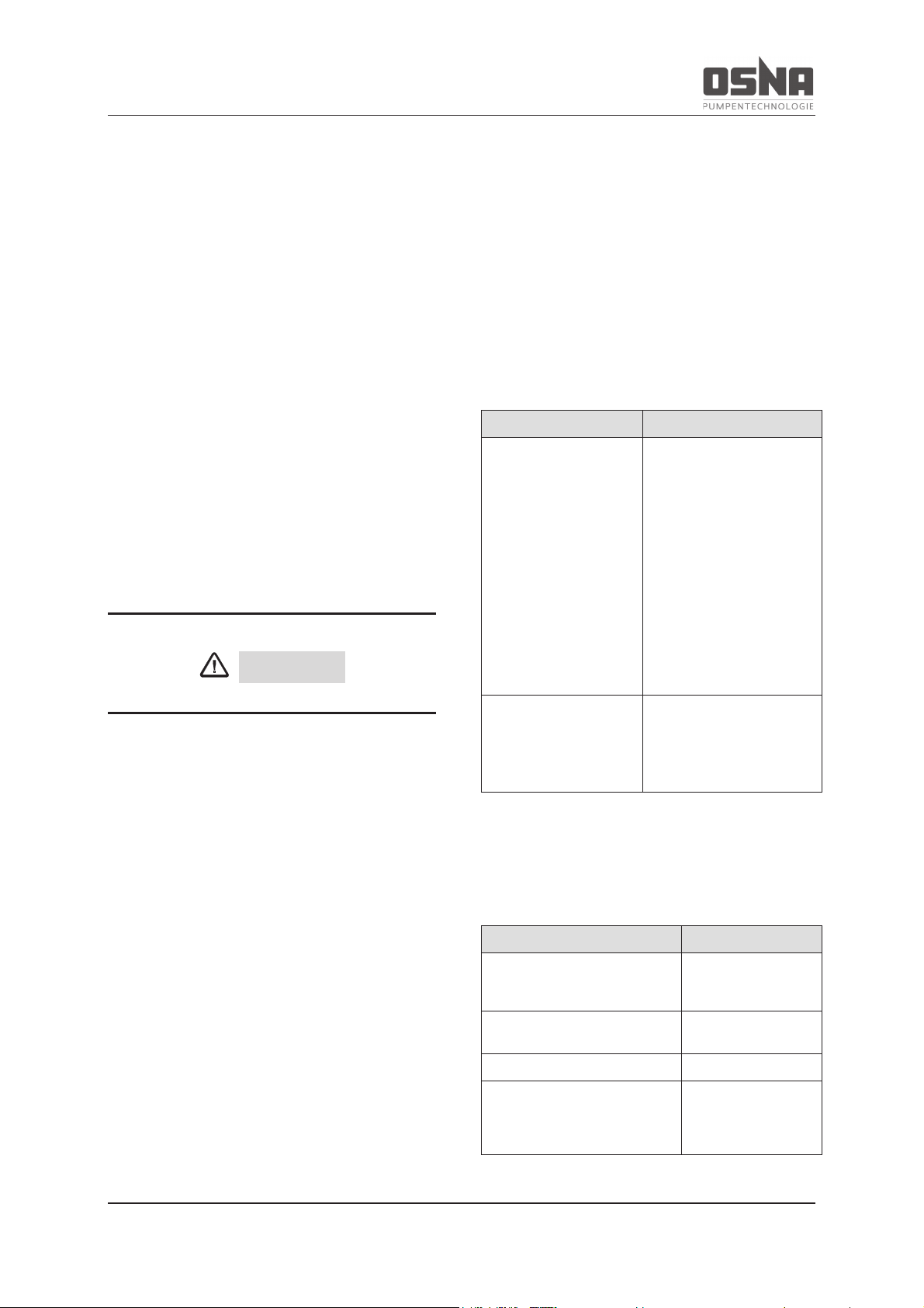
1.4 Warning notices and symbols
Warning notice
Hazard
level
Consequences of non
-
observance
DANGER
Immediate
hazard
Death, severe
physical injury
WARNING
Potential
hazard
Death, severe
physical injury
CAUTION
Potentially
dangerous
situation
Minor physical
injury
NOTICE
Potentially
dangerous
situation
Material damage
Additional
information
on explosion
pr
o-
tection
Death, minor to
severe physical
injuries, material damage
Table 3: Warning notices and consequences
of non-observance
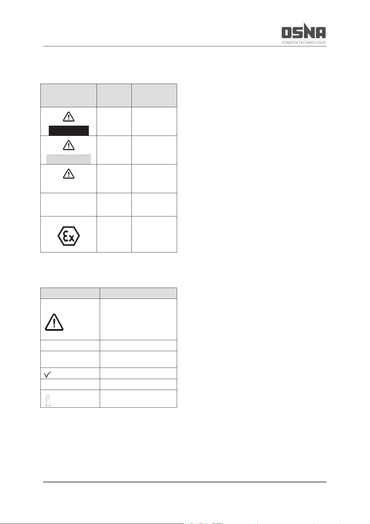
Symbol
Meaning
Safety sign
► Follow all instructions
identified with safety signs
in order to avoid death or
injuries.
►
Instruction
1. , 2. , …
Instruction with multiple
steps
Condition
→
Reference
Information, note
Table 4: Symbols and their meanings
1.5 Copyright/changes
The intellectual property and all copyrights
related to this technical documentation remain
exclusively with OSNA-Pumpen GmbH. All
rights reserved, in particular the right to reproduction and distribution of this documentation,
including translations thereof.
No part of this documentation may be reproduced in any form (print, photocopy, microfilm
or any others process), stored, processed,
reproduced or distributed using electronic systems without written permission.
Editorial changes reserved exclusively by
OSNA-Pumpen GmbH.
Any violation is punishable and subject to
compensation.
OSNA GmbH reserves the right to change the
contents of this documentation without notice.
2 Safety
8 NMH/NMV High Pressure Centrifugal Pump
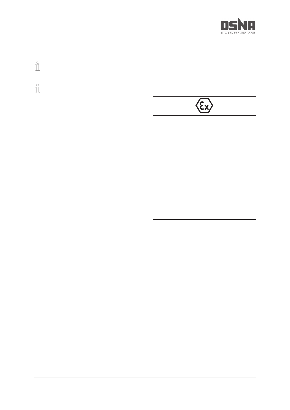
2 Safety
Observe the additional instructions for
pumps in areas at risk of explosion.
The manufacturer shall not bear any liability
for damages caused as a result of nonobservance of this documentation.
2.1 Correct and proper use
· Only use this pump for the purposes of
conveying the agreed pumping media.
· Comply with operating limits.
· The water may not contain any abra-
sive or long-fibered components that
may damage the pump materials.
Consult the manufacturer if using other
media.
· Ensure that the pump is only commis-
sioned with pumping medium and is
not operated without it.
· Open the suction-side fitting, and do
not use it to control the flow rate.
· To avoid damaging the motor, observe
the permitted number of times per
hour that the motor can be switched
on (→ Manufacturer information).
· Any other use must be agreed with the
manufacturer.
· The temperature of the pumping me-
dium must not exceed 140 °C.
Avoiding obvious misuse (examples)
· Observe the operating limits of the
pump for temperature, pressure, flow
rate and speed.
The use of pumps in ATEX zones is subject
to additional specifications related to correct and proper use!
► Do not operate the pump:
- when the fittings are closed
- when the operating range is exceeded
(à data sheet)
- when maintenance intervals are ex-
ceeded
à 9.1.1 Safety, pg 55
The main areas of use are:
· Pressure boosting systems, heating
systems, hot and cold water circulation, water supply systems, power stations, filtering systems, filling and emptying of tanks, water circulation in
pools and sprinkler systems
· Fresh water, drinking water, boiler
feed water, process water, sea and
brackish water, hot water, condensate
and many media without aggressive
components that do not chemically
corrode the materials used in the
pump
Do not operate the pump without pumping
medium. Dry running can lead to damage to
the pump.
2 Safety
NMH/NMV High Pressure Centrifugal Pump 9
WARNING
Any use that goes beyond the purposes
described above shall be considered improper use. OSNA shall bear no liability for
any resulting damages. The owner bears
full risk for improper use.
2.2 General safety instructions
Please observe the following specifications
before performing any activities.
2.2.1 Product safety
This pump is constructed according to the
latest state of the art and accepted safety
rules. Nevertheless, risks to life and limb for
the user or third parties are still possible when
using the pump, as are impairments to the
pump and other material assets.
· Only use the pump in a technically
perfect state and for the intended purpose. Ensure compliance with this operating manual and be aware of the
hazards and safety issues during operation.
· Keep this operating manual and all
other valid documents in a complete
and legible state, and store in a location that is accessible at all times to
personnel.
· Do not permit any activity that endan-
gers personnel or uninvolved third parties.
· In the event of a safety-relevant fault,
stop the pump immediately and have
the fault rectified by responsible personnel.
· In addition to this documentation, en-
sure compliance with the statutory or
other regulations for safety and accident prevention, as well as the relevant standards and specifications of
the respective country.
· Do not remove any technical stickers.
2.2.2 Duties of the system owner
Safety-conscious work
Observe the safety specifications detailed in
this operating manual, along with the occupational safety regulations and all additional internal safety regulations.
· Only use the pump in a technically
perfect state and for the intended purpose. Ensure compliance with this operating manual and be aware of the
hazards and safety issues during operation.
· Ensure compliance and monitoring:
- correct and proper use
- statutory or other safety and acci-
dent prevention regulations
- safety specifications for handling
hazardous substances
· Provide personal protective equip-
ment.
· Do not remove contact protection dur-
ing operation.
· Prevent any dangers from electrical
energy (for details, please refer to the
2 Safety
10 NMH/NMV High Pressure Centrifugal Pump
specifications of the VDE and the local
energy supplier).
· Switch off the motor during all assem-
bly and maintenance works, and secure against reactivation.
· Only work on the system when the
pump is at a standstill.
Personnel qualification
The owner of the system must ensure that the
personnel tasked with working on the pump
have read and understood this operating manual and all other valid documents before beginning work, in particular information on safety, maintenance and repair.
Work of any kind on the machine may only be
performed when it has been completely decommissioned. Reinstall and reactivate all
safety mechanisms after work.
Before restarting the machine, ensure that all
necessary commissioning steps have been
completed.
· Determine responsibilities, tasks and
monitoring for personnel.
· Only allow work of any kind to be per-
formed by specialist technical personnel:
- assembly, maintenance and repair
work
- work on the electrical systems
· Only allow personnel undergoing train-
ing to perform work on the pump under
the supervision of specialist technical
personnel.
Safety mechanisms
· Provide the following safety mecha-
nisms and ensure that they function
correctly:
- for moving components: contact
protection for the pump, installed
by the customer
- for potential electrostatic charges:
provide appropriate earthing
Guarantee
· Please consult the manufacturer be-
fore carrying out any conversions, repairs or changes during the guarantee
period.
· Only use original parts or parts ap-
proved by the manufacturer.
The use of pumps in ATEX zones is subject
to additional specifications related to work
safety!
à 9.1.1 Safety, pg 55
2.2.3 Duties of personnel
· Observe the information on the pump
and ensure it is legible (e.g. direction
of rotation arrow, fluid connection indicators).
· Do not remove the contact protection
for moving parts during operation.
· Use personal protective equipment if
necessary.
· Only work on the system when the
pump is at a standstill.
2 Safety
NMH/NMV High Pressure Centrifugal Pump 11
· Switch off the motor during all assem-
bly and maintenance works, and secure against reactivation.
· Reinstall the safety mechanisms after
working on the pump according to
specifications.
2.3 Dangers of non-observance of
the safety instructions
· Non-observance of the safety instruc-
tions can lead to hazards to personnel,
the machine and the environment.
· Non-observance of the safety instruc-
tions can also lead to the loss of any
damage claims.
· In particular, non-observance can lead
to the following dangers:
- failure of important system func-
tions
- electrical and mechanical hazards
to personnel
2.4 Unauthorized conversion and
production of spare parts
Conversions or changes to the machine are
only permitted following consultation with the
manufacturer. Original spare parts and accessories authorized by the manufacturer help
ensure safety. The manufacturer bears no
liability for the consequences of the use of
other parts.
2.5 Unauthorized modes of operation
The operational safety of the machine is only
guaranteed when it is used for the intended
purpose according to the operating manual (→
2.1 Correct and proper use, pg 8).
Never exceed the limit values indicated in the
technical data (→ Data sheet).
2.6 Special hazards
2.6.1 Explosion area
· Only use pumps with ATEX certifica-
tion in areas at risk of explosion. (à
3.1.2 Type plate, pg 13)
The use of pumps in ATEX zones is subject
to additional requirements!
à 9.1 Additional ATEX instructions, pg 55
2.6.2 Hazardous pumping media
· Observe the safety regulations for
handling hazardous substances (e.g.
toxic, hazardous to health).
· Use personal protective equipment
when performing work on the pump.
2 Safety
12 NMH/NMV High Pressure Centrifugal Pump
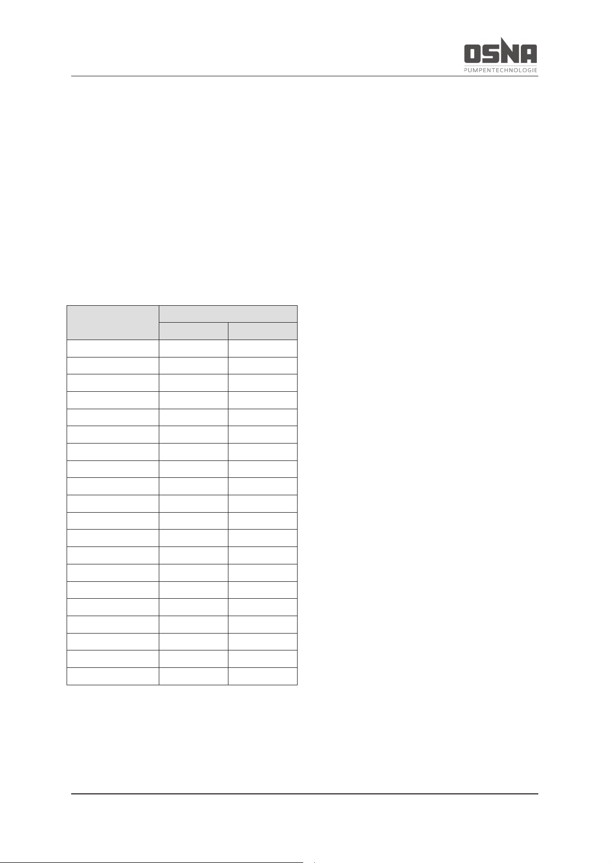
2.6.3 Noise emissions
Conditions for measurement:
· Distance to pumping unit: 1 m
· Operation: Free of cavitation
· Motor: IEC standard motor
· Tolerance: ± 3 dB(A)
Drive power in kW
Noise emissions in dB(A)
1450 min-1
2900 min-1
0.75
50
58
1.1
53
62
1.5
55
62
2.2
56
63
3.0
58
65
4.0
60
66
5.5
64
70
7.5
65
71
11.0
68
73
15.0
69
74
18.5
69
74
22.0
70
75
30.0
71
75
37.0
72
76
45.0
73
77
55.0
73
79
75.0
74
81
90.0
74
82
110.0
75
83
132.0
76
84
Table 5: Sound pressure level
Low-noise motors can be provided if the expected noise values exceed the permitted limits.
3 Layout and function
NMH/NMV High Pressure Centrifugal Pump 13
3 Layout and function
3.1 Labeling
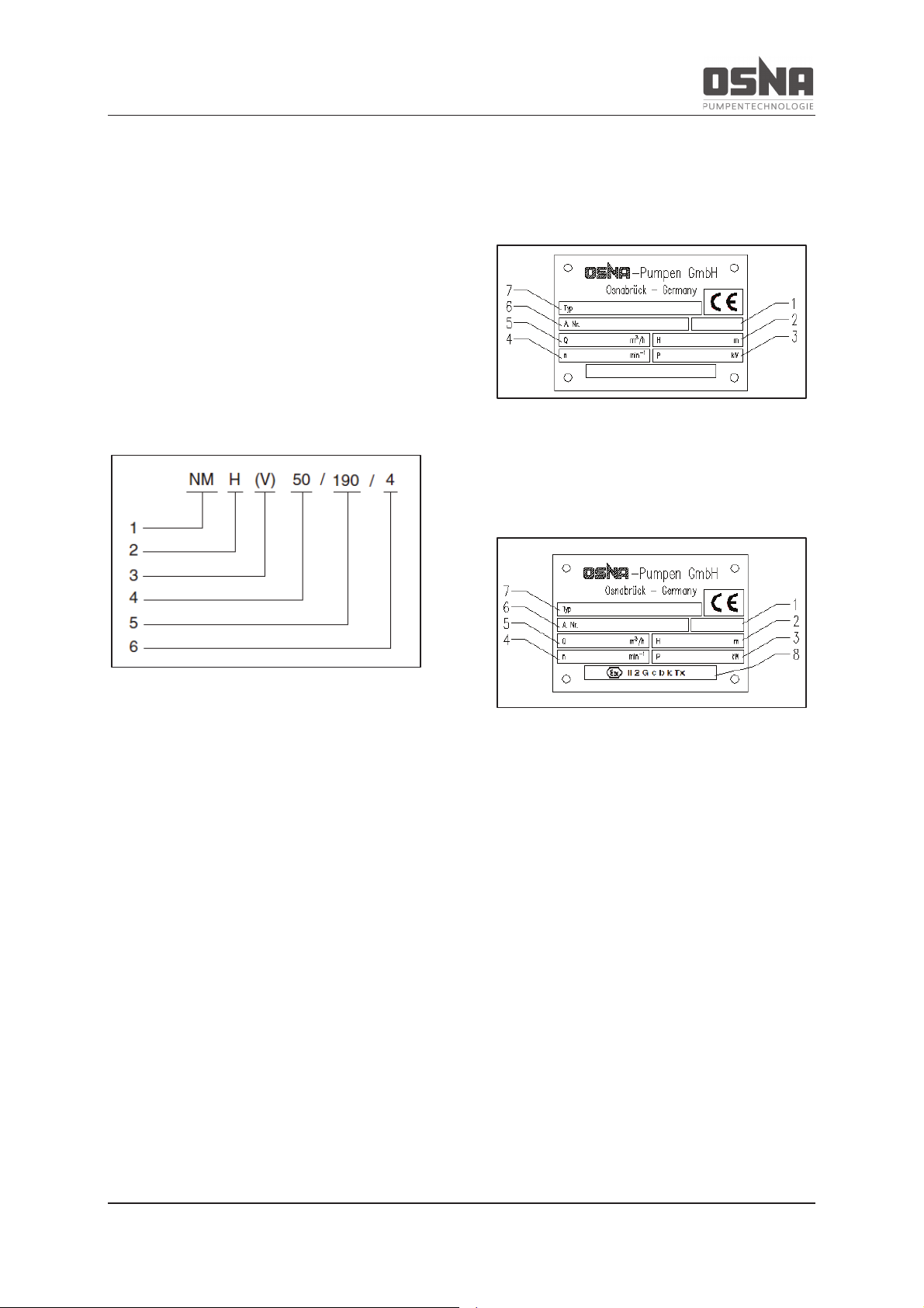
3.1.1 Pump type labeling
This operating manual applies to the
NMH/NMV type series.
Model code:
Figure 1: Model code
Key:
1 Type series
2 Horizontal configuration
3 Vertical configuration
4 Nominal diameter of discharge nozzle
[mm]
5 Max. impeller diameter [mm]
6 Number of stages
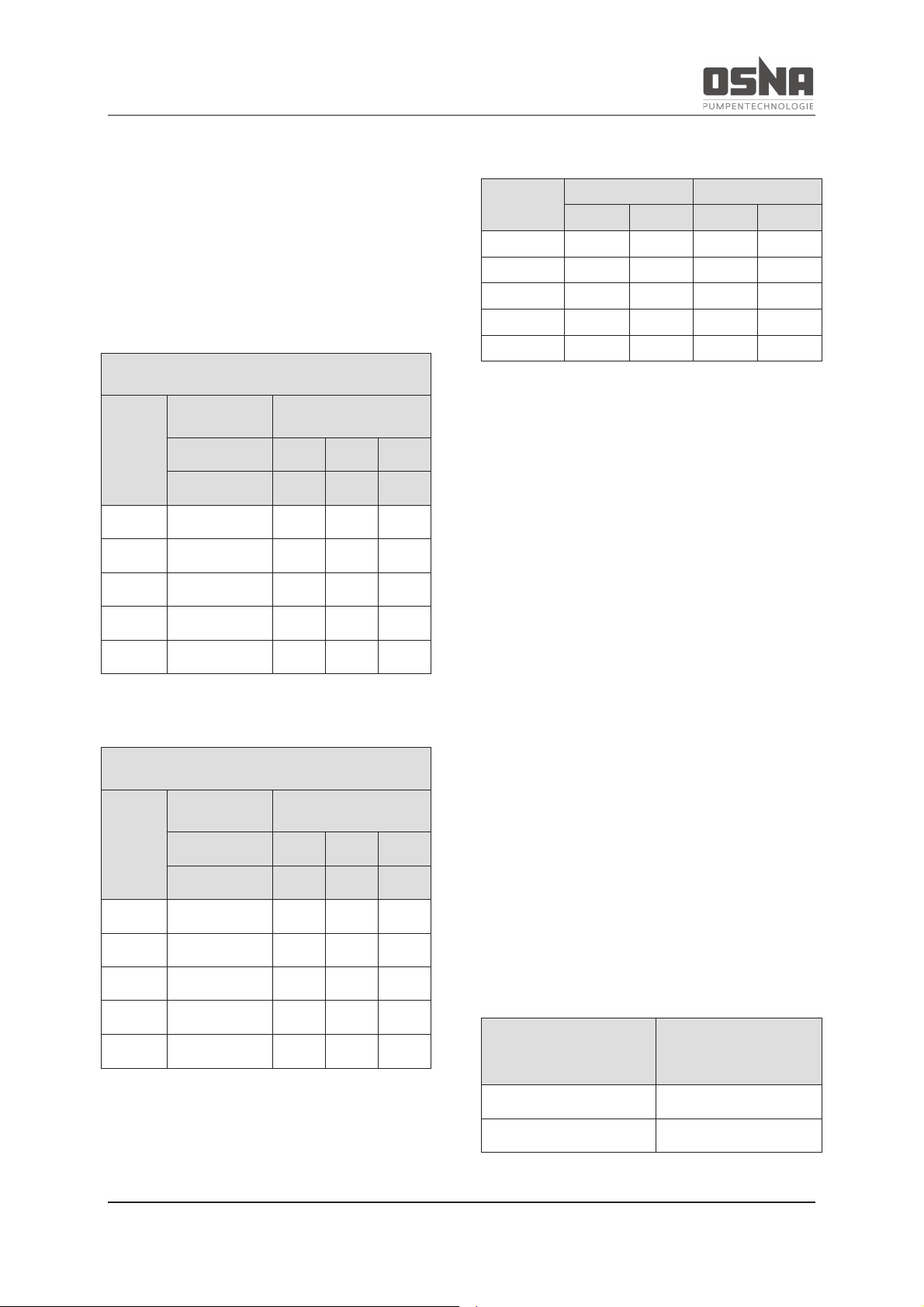
3.1.2 Type plate
Standard configuration:
Figure 2: Standard version type plate
ATEX configuration:
Figure 3: ATEX version type plate
Key:
1 Year of production
2 Delivery head [m]
3 Power requirements [kW]
4 Speed [min-1]
5 Flow rate [m³/h]
6 Pump number
7 Pump type
8 ATEX protection class

3 Layout and function
14 NMH/NMV High Pressure Centrifugal Pump
3.2 Scope of delivery of an
NMH/NMV high-pressure centrifugal
pump
The customer can order the pump:
- with a free shaft (NMH) or without motor
(NMV)
- as a complete unit, i.e. fully assembled on
base plate with drive motor, coupling and
coupling guard
Figure 4: Scope of delivery for NMH with free shaft
Figure 5: Scope of delivery for NMV without motor
Figure 6: Scope of delivery for NMH as complete unit
Figure 7: Scope of delivery for NMV as complete unit
Key:
1 Pump
2 Drive motor
3 Baseplate
4 Coupling
5 Coupling guard
6 Pump base
The scope of delivery corresponds to the
scope indicated in the order. Please check that
the delivery is complete upon receipt. Notify
the delivery company of any transport damage
immediately. Please also refer to our conditions of sale and delivery. If using other motor
brands, please ensure that the motors have
the following drive torques as a multiple of the
nominal torque.
3.3 General information
The NMH/NMV pump series are non selfpriming, multistage, high-pressure centrifugal
pumps in horizontal and vertical configuration.
The suction and discharge nozzles can be
installed at different stages of 90°.
The horizontal-configuration pumps are fitted
with anti-friction bearings. The verticalconfiguration pumps have one anti-friction
bearing (pressure side) and one plain bearing
(suction side).
3 Layout and function
NMH/NMV High Pressure Centrifugal Pump 15
Both vertical and horizontal pumps can be
fitted with either an uncooled mechanical seal
or an uncooled gland packing.
3.4 Technical data
Main parameters:
NMH/NMV at speed = 1450 min-1
(gray cast iron)
Series
Delivery
head
Flow rate
H
max
Q
min
Q
opt
Q
max
m
m³/h
m³/h
m³/h
32
104
1.8
8.5
12
40
110
3.75
16.0
25
50
154
5.25
30.0
35
65
198
9.75
42.0
65
80
226
15.0
65.0
100
Table 6: Main parameters at 1450 rpm
NMH/NMV at speed = 2900 min-1
(gray cast iron)
Series
Delivery
head
Flow rate
H
max
Q
min
Q
opt
Q
max
m
m³/h
m³/h
m³/h
32
336
3.3
16.5
22
40
362
6.6
30.0
44
50
381
10.1
50.0
67
65
400
16.5
80.0
110
80
400
27
135.0
180
Table 7: Main parameters at 2900 rpm
Flange:
NMH/NMV
series
Suction side
Pressure side
NPS
PN
NPS
PN
32
50
40
32
40
40
65
40
40
40
50
80
40
50
40
65
100
40
65
40
80
125
40
80
40
Table 8: Pump series' flange sizes
Drive unit:
NMH: 50 and 60 Hz electric motor, diesel
motor or turbine
NMV: Electric motor with IEC flange, V1 con-
figuration or hydraulic motor with special flange
3.5 Operating point
In order to reach the required operating point,
it may be necessary to fit the pump with two
different sizes of impeller blade. For this reason, please provide the impeller blade diameter or position on the shaft when ordering
spare parts (1st, 2nd impeller, etc., beginning
at the suction side of the pump).
Please always indicate the pump type and
order number when ordering spare parts, or in
the event of any queries.
3.6 Minimum output rates
Pump tempe
rature
range
Minimum output rate
at design point
–
10 to +100 °C
15% of Q
opt
+100 to +140°C
20% of Q
opt
Table 9: Minimum output rates with closed
shut-off valve
3 Layout and function
16 NMH/NMV High Pressure Centrifugal Pump
3.7 Functional and operating ele-
ments
Shaft wearing sleeve:
Shaft
wearing
sleeve
NMH
NMV
Uncooled gland
packing
Up to 110 °C
Up to 100 °C
Uncooled mechanical seal
Up to 140 °C
Up to 140 °C
Table 10: Maximum authorized operating temperature
at the shaft seal
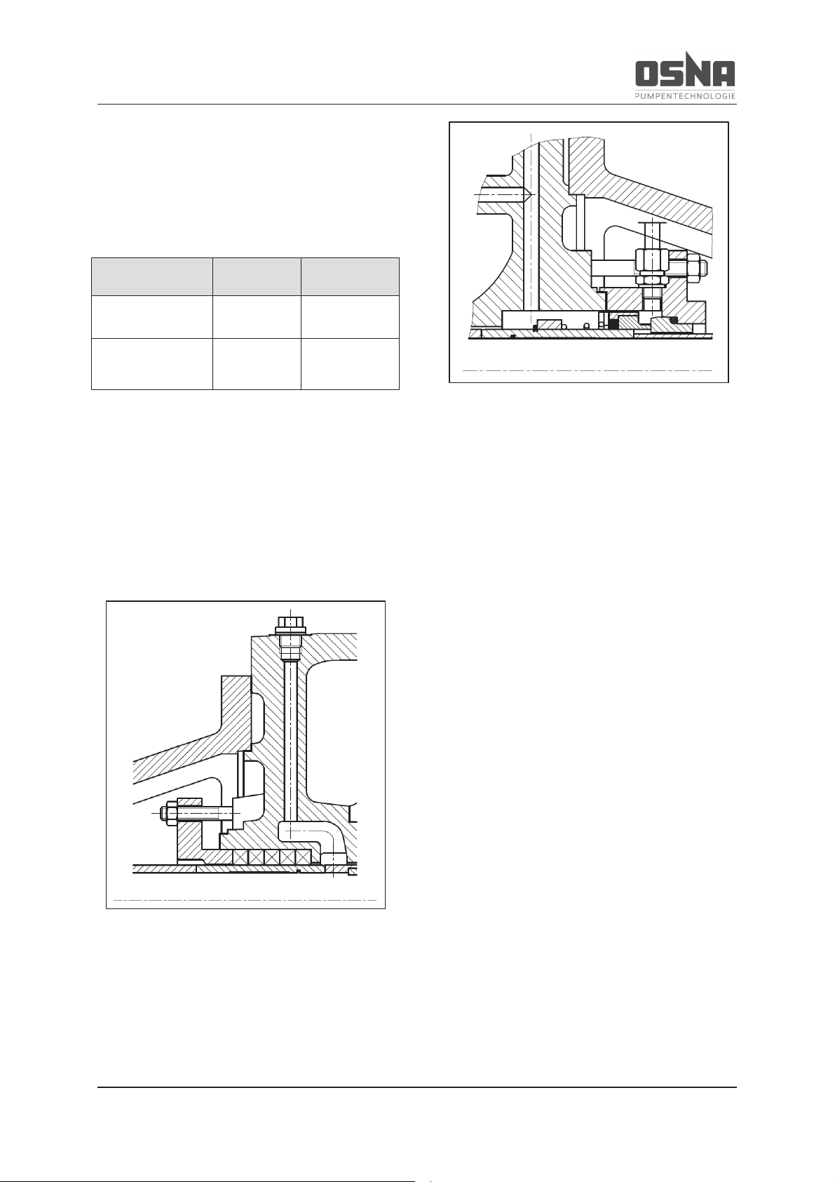
The pumps can be fitted with gland packing or
mechanical seal as required.
Gland packing consists of a number of compression-molded rings in a stuffing box. Gland
packings can be adjusted by hand with tools.
Figure 8: Gland packing
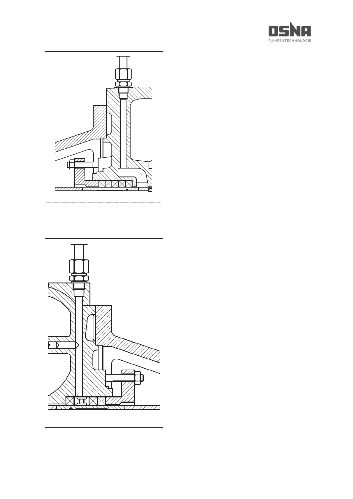
Mechanical seals are mechanical shaft seals
with internal flushing of the rotating seal rings
(self-adjusting).
Figure 9: Mechanical seal
The technical dry running properties of gland
packing and mechanical seals are extremely
limited. For this reason, avoid dry running.
Ensure that the pump is vented before commissioning.
3.8 Auxiliary operating systems
When blocking, the pressure of the sealing
medium is higher than that of the pumping
medium.
Example: Pumping media that crystallize or
are laden with solid particles, and can therefore damage the seal over time.
3 Layout and function
NMH/NMV High Pressure Centrifugal Pump 17
Figure 10: Pressure-side external flushing
connection (optional)
Figure 11: Suction-side external flushing
connection (optional)
4 Transport and intermediate storage
18 NMH/NMV High Pressure Centrifugal Pump
4 Transport and intermediate
storage
4.1 Transport
Weight information (→ Other valid docu-
ments)
4.1.1 Unpacking and checking the de-
livery condition
1. Check that the delivery is complete
upon receipt.
2. Unpack the pump/unit upon delivery
and check for transport damage.
3. Notify the delivery company of any
transport damage immediately.
4. Dispose of the packaging material in
line with the applicable local regulations.
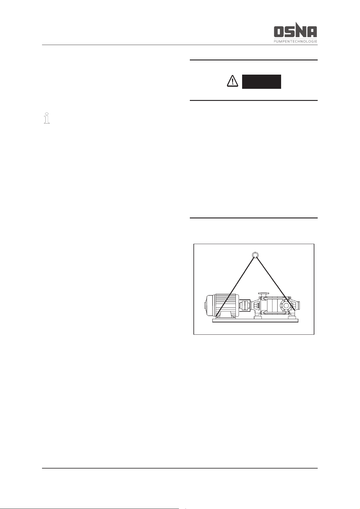
4.1.2 Lifting
Transport the pumps carefully and secure
them to prevent damage. If using a horizontal
pump, transport the entire unit using ropes as
shown in Figure 12 (pg 18) (do not secure the
ropes on the motor eyelets). Transport vertical
pumps as shown in Figure 14 (pg 19).
DANGER
Risk of death or crushed limbs from falling
transported goods!
► Choose lifting equipment that is suitable for
the total weight to be transported.
► Secure the lifting equipment according to
the following images.
► Do not stand under suspended loads.
Figure 12: Lifting an NMH centrifugal pump (unit)
4 Transport and intermediate storage
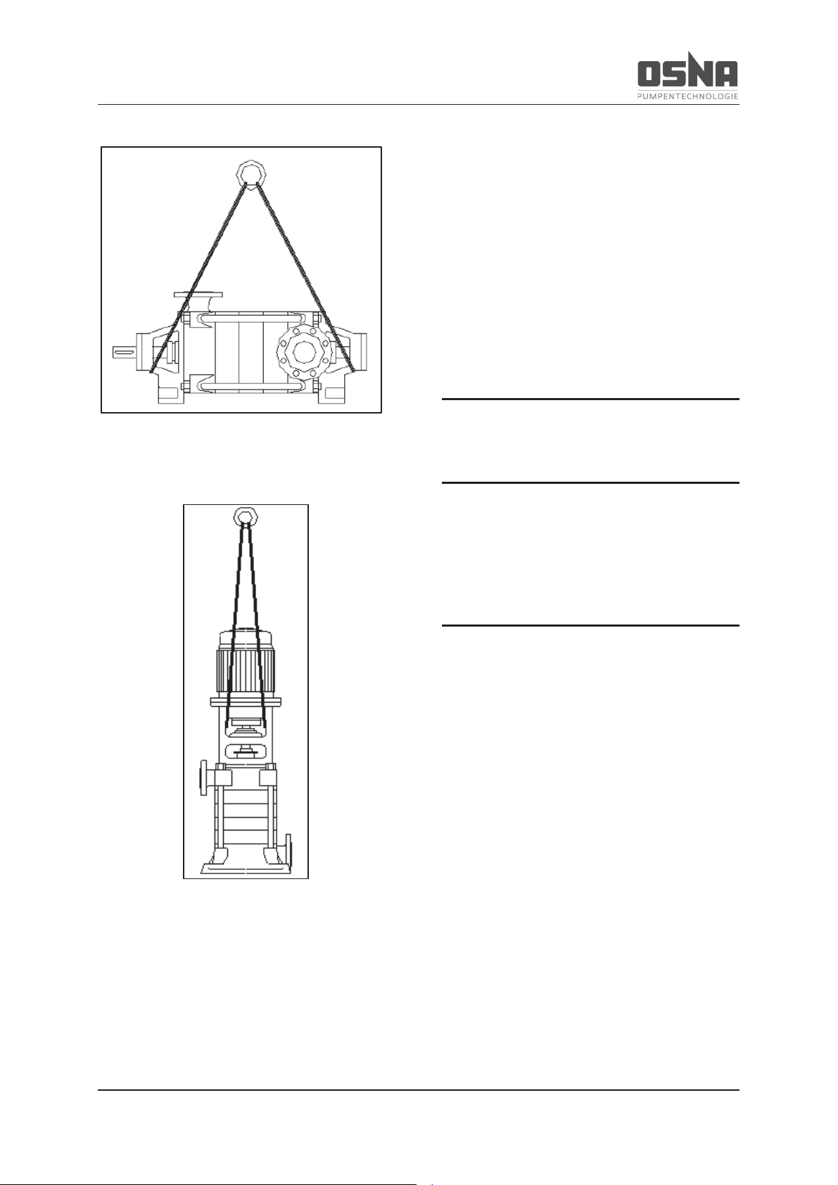
NMH/NMV High Pressure Centrifugal Pump 19
Figure 13: Lifting an NMH centrifugal pump
(free shaft end)
Figure 14: Lifting an NMV centrifugal pump
4.2 Intermediate storage
Ensure during intermediate storage that the
pump is not exposed to any weather conditions
for a long period of time. If the pump is decommissioned for a longer period of time (approximately 2 to 3 months), ensure that it is
fully drained. (→ 6.2 Decommissioning, pg 39)
4.3 Storage
NOTICE
Material damage due to incorrect storage!
► Ensure that the pump is correctly
stored.
1. Close all openings with blank flanges,
blind plugs or plastic covers.
2. Ensure that the storage area meets
the following conditions:
– dry
– free of frost
– free of vibrations
3. Rotate the shaft once per month by
several rotations.
4 Transport and intermediate storage
20 NMH/NMV High Pressure Centrifugal Pump
NOTICE
Damage to bearings due to high water
pressure or splashing water!
► Do not use water jets or steam jet cleaners
to clean the bearing areas and motor.
NOTICE
Damage to seals due to incorrect cleaning
agent!
► Ensure that the cleaning agent does not
corrode the seals.
1. Choose the cleaning agent according
to the area of use.
2. Dispose of preservatives in line with
the applicable local regulations.
3. When storing for longer than 6
months:
– Check all elastomers (round seals,
shaft seal rings, gaskets and gland
packing) for elasticity, and replace
if necessary.
4.4 Disposal
Plastic parts may be contaminated by toxic
or radioactive pumping media. If this is the
case, cleaning is not sufficient.
WARNING
Risk of poisoning and environmental damage from pumping medium!
► Use personal protective equipment when
performing work on the pump.
► Before disposing of the pump:
– Collect any remaining pumping
medium in the pump, and dispose
of it in line with the locally valid
regulations.
– Neutralize any pumping medium
residues in the pump.
► Dispose of the pump in line with the appli-
cable local regulations.
 Loading...