

Page 1
Ver.17-02
Original Operating Manual
NMH/NMV High-Pressure
Centrifugal Pump
OSNA-Pumpen GmbH
Brückenstrasse 3
49090 Osnabrück, Germany
Phone: +49 541 1211 - 0
Fax: +49 541 1211 - 220
Internet: http://www.osna.de
E-mail: [email protected]
Page 2

Page 3

NMH/NMV High Pressure Centrifugal Pump 1
Contents
1 GENERAL ........................................................................................................................................ 6
1.1 About this operating manual .................................................................................................... 6
1.2 Target groups .......................................................................................................................... 6
1.3 Other valid documents ............................................................................................................. 6
1.4 Warning notices and symbols .................................................................................................. 7
1.5 Copyright/changes ................................................................................................................... 7
2 SAFETY ........................................................................................................................................... 8
2.1 Correct and proper use ............................................................................................................ 8
2.2 General safety instructions ...................................................................................................... 9
2.2.1 Product safety ...................................................................................................................... 9
2.2.2 Duties of the system owner ................................................................................................. 9
2.2.3 Duties of personnel ............................................................................................................ 10
2.3 Dangers of non-observance of the safety instructions .......................................................... 11
2.4 Unauthorized conversion and production of spare parts ....................................................... 11
2.5 Unauthorized modes of operation ......................................................................................... 11
2.6 Special hazards ..................................................................................................................... 11
2.6.1 Explosion area ................................................................................................................... 11
2.6.2 Hazardous pumping media ................................................................................................ 11
2.6.3 Noise emissions................................................................................................................. 12
3 LAYOUT AND FUNCTION ............................................................................................................ 13
3.1 Labeling ................................................................................................................................. 13
3.1.1 Pump type labeling ............................................................................................................ 13
3.1.2 Type plate .......................................................................................................................... 13
3.2 Scope of delivery of an NMH/NMV high-pressure centrifugal pump ..................................... 14
3.3 General information ............................................................................................................... 14
3.4 Technical data ....................................................................................................................... 15
3.5 Operating point ...................................................................................................................... 15
3.6 Minimum output rates ............................................................................................................ 15
3.7 Functional and operating elements ....................................................................................... 16
3.8 Auxiliary operating systems ................................................................................................... 16
4 TRANSPORT AND INTERMEDIATE STORAGE ......................................................................... 18
4.1 Transport ............................................................................................................................... 18
4.1.1 Unpacking and checking the delivery condition ................................................................ 18
4.1.2 Lifting ................................................................................................................................. 18
4.2 Intermediate storage .............................................................................................................. 19
4.3 Storage .................................................................................................................................. 19
4.4 Disposal ................................................................................................................................. 20
Page 4

2 NMH/NMV High Pressure Centrifugal Pump
5 ASSEMBLY AND INSTALLATION ............................................................................................... 21
5.1 Preparing for installation ........................................................................................................ 21
5.1.1 Preparing the installation location...................................................................................... 21
5.1.2 Preparing the base surface and foundations ..................................................................... 21
5.1.3 Removing the preservative ................................................................................................ 22
5.2 Installation .............................................................................................................................. 23
5.2.1 Installing the pump ............................................................................................................ 23
5.2.2 Securing the pump unit ...................................................................................................... 25
5.2.3 Assembling the motor ........................................................................................................ 25
5.3 Fine alignment of the coupling ............................................................................................... 26
5.3.1 Horizontal configuration ..................................................................................................... 26
5.3.2 Vertical configuration ......................................................................................................... 27
5.4 Aligning the motor .................................................................................................................. 28
5.4.1 Aligning the motor with shims ............................................................................................ 28
5.4.2 Aligning the motor with adjustment screws ....................................................................... 28
5.5 Planning pipelines ................................................................................................................. 29
5.5.1 General .............................................................................................................................. 29
5.5.2 Avoiding contaminations in the pipelines .......................................................................... 31
5.5.3 Configuring supports and flange connections ................................................................... 31
5.5.4 Determining nominal widths .............................................................................................. 31
5.5.5 Determining pipeline lengths ............................................................................................. 31
5.5.6 Optimizing changes in cross-section and direction ........................................................... 32
5.5.7 Providing safety and monitoring systems (recommended) ............................................... 32
5.6 Attaching the pipelines .......................................................................................................... 32
5.6.1 Installing auxiliary pipelines ............................................................................................... 32
5.6.2 Installing the suction pipe .................................................................................................. 33
5.6.3 Installing the pressure pipe ................................................................................................ 33
5.6.4 Checking for lack of tension in the pipeline connection .................................................... 33
5.7 Electrical connection .............................................................................................................. 34
5.7.1 Connecting the motor ........................................................................................................ 34
5.7.2 Earthing the pump ............................................................................................................. 35
6 COMMISSIONING/ DECOMMISSIONING .................................................................................... 36
6.1 Commissioning ...................................................................................................................... 36
6.1.1 Determining the pump configuration.................................................................................. 36
6.1.2 Filling the pump ................................................................................................................. 36
6.1.3 Checking direction of rotation ............................................................................................ 37
6.1.4 Starting the pump .............................................................................................................. 38
6.2 Decommissioning .................................................................................................................. 39
6.2.1 Switching off the pump ...................................................................................................... 41
6.2.2 Draining the pump and protecting against frost ................................................................. 41
6.3 Recommissioning .................................................................................................................. 41
Page 5

NMH/NMV High Pressure Centrifugal Pump 3
6.4 Operating the stand-by pump ................................................................................................ 41
6.5 Shaft seal ............................................................................................................................... 42
6.5.1 Mechanical seal ................................................................................................................. 42
6.5.2 Gland packing .................................................................................................................... 42
7 MAINTENANCE AND REPAIR ..................................................................................................... 43
7.1 General information ............................................................................................................... 43
7.2 Operational monitoring .......................................................................................................... 44
7.3 Maintenance .......................................................................................................................... 45
7.3.1 Anti-friction bearings and grease lubrication ..................................................................... 46
7.3.2 Servicing the electric motors ............................................................................................. 46
7.3.3 Servicing the mechanical seals ......................................................................................... 47
7.3.4 Servicing the gland packing ............................................................................................... 47
7.4 Sending the pump to the manufacturer ................................................................................. 48
7.5 Disassembling the pump ....................................................................................................... 49
7.6 Ordering spare parts .............................................................................................................. 51
8 FAULTS AND TROUBLESHOOTING ........................................................................................... 52
9 APPENDIX ..................................................................................................................................... 55
9.1 Additional ATEX instructions ................................................................................................. 55
9.1.1 Safety ................................................................................................................................. 55
9.1.2 Explosion protection marking ............................................................................................ 56
9.1.3 Installation and connection ................................................................................................ 57
9.1.4 Operation ........................................................................................................................... 59
9.1.5 Maintenance and repair ..................................................................................................... 59
9.2 Spare parts list for constant operation over two years as per DIN 24296 ............................. 60
9.3 Cross-sections ....................................................................................................................... 61
9.4 Declaration of Conformity as per EC Directive 2006/42/EC, Annex IIA ................................ 67
9.5 Declaration of Conformity as per EC Directive 2014/34/EC, Annex VI ................................. 68
9.6 Clearance Certificate ............................................................................................................. 69
Page 6

4 NMH/NMV High Pressure Centrifugal Pump
List of Tables
Table 1: Target groups and their tasks .................................................................................................... 6
Table 2: Other valid documents and their purposes .............................................................................. 6
Table 3: Warning notices and consequences of non-observance ......................................................... 7
Table 4: Symbols and their meanings ..................................................................................................... 7
Table 5: Sound pressure level ............................................................................................................... 12
Table 6: Main parameters at 1450 rpm ................................................................................................. 15
Table 7: Main parameters at 2900 rpm ................................................................................................. 15
Table 8: Pump series' flange sizes ........................................................................................................ 15
Table 9: Minimum output rates with closed shut-off valve ................................................................... 15
Table 10: Maximum authorized operating temperature at the shaft seal .............................................. 16
Table 11: Ambient conditions ................................................................................................................ 21
Table 12: Settings for the time relay when using three-phase motors with star-delta switch ............... 35
Table 13: Measures depending on the behavior of the pumping medium ........................................... 40
Table 14: Measures in the event of operational interruption ................................................................ 40
Table 15: Measures following longer shut down times ......................................................................... 41
Table 16: Stuffing box dimensions ........................................................................................................ 48
Table 17: Measures for return ............................................................................................................... 49
Table 18: Fault/number allocation ......................................................................................................... 52
Table 19: Troubleshooting table ............................................................................................................ 54
Table 20: Temperature classes ............................................................................................................. 56
Table 21: Ignition protection classes ..................................................................................................... 56
Table 22: Ex atmosphere ...................................................................................................................... 57
Table 23: Equipment groups/areas of use/zone/category ..................................................................... 57
Table 24: Possible devices for monitoring self-warming due to dry running ......................................... 58
Table 25: Measures against unauthorized self-warming ....................................................................... 58
Table 26: Max. pumping medium temperature...................................................................................... 59
Table 27: Spare parts for constant operation over two years ............................................................... 60
Table 28: NMH parts list ........................................................................................................................ 63
Table 29: NMV parts list ........................................................................................................................ 66
Page 7

NMH/NMV High Pressure Centrifugal Pump 5
List of Images
Figure 1: Model code ............................................................................................................................. 13
Figure 2: Standard version type plate ................................................................................................... 13
Figure 3: ATEX version type plate ......................................................................................................... 13
Figure 4: Scope of delivery for NMH with free shaft .............................................................................. 14
Figure 5: Scope of delivery for NMV without motor ............................................................................... 14
Figure 6: Scope of delivery for NMH as complete unit .......................................................................... 14
Figure 7: Scope of delivery for NMV as complete unit .......................................................................... 14
Figure 8: Gland packing ........................................................................................................................ 16
Figure 9: Mechanical seal ...................................................................................................................... 16
Figure 10: Pressure-side external flushing connection (optional) ........................................................ 17
Figure 11: Suction-side external flushing connection (optional)........................................................... 17
Figure 12: Lifting an NMH centrifugal pump (unit) ................................................................................ 18
Figure 13: Lifting an NMH centrifugal pump (free shaft end) ............................................................... 19
Figure 14: Lifting an NMV centrifugal pump .......................................................................................... 19
Figure 15: Mounting material for complete units ................................................................................... 23
Figure 16: Mounting material for pump with open shaft end ................................................................ 23
Figure 17: Aligning the base plate ......................................................................................................... 24
Figure 18: Positional alignment of the shafts ........................................................................................ 26
Figure 19: Directional alignment of the shafts ....................................................................................... 26
Figure 20: Aligning the motor with adjustment screws .......................................................................... 28
Figure 21: Functional and operating elements ...................................................................................... 29
Figure 22: Recommended straight pipeline lengths upstream and downstream of the pump .............. 31
Figure 23: NMH earthing screws ........................................................................................................... 35
Figure 24: NMV earthing screws ........................................................................................................... 35
Figure 25: Pressure-side stuffing box (standard) .................................................................................. 48
Figure 26: Suction-side stuffing box (standard) .................................................................................... 48
Figure 27: Cross-section of NMH with mechanical seal ........................................................................ 61
Figure 28: Cross-section of NMH with gland packing ........................................................................... 62
Figure 29: Cross-section of NMV with mechanical seal ........................................................................ 64
Figure 30: Cross-section of NMV with gland packing ........................................................................... 65
Page 8
1 General
6 NMH/NMV High Pressure Centrifugal Pump
1 General
1.1 About this operating manual
This operating manual contains important instructions that must be observed during installation, operation and maintenance. For this
reason, ensure that it is read by specialist personnel and the responsible operator/owner
prior to assembly and commissioning. The
manual must be available at all times at the
location where the system is used.
Please observe the safety instructions described in this operating manual, along with the
relevant national accident prevention regulations and any internal work, operational and
safety specifications of the operator. We assume no liability for damages and operational
interruptions resulting from non-observance of
this operating manual.
WARNING
Pay particular attention to section 2 "Safety
instructions" during commissioning and all
maintenance work.
Section 2 also provides an explanation of the
symbols used in this manual. Knowledge of
this operating manual is essential to preventing
errors and ensuring safe and uninterrupted
operation.
The operating specification does not take local
safety regulations into account. The owner
bears full responsibility for compliance with
these, including on the part of the assembly
personnel used.
This operating manual:
· is part of the pump
· is valid for all type series mentioned
· describes safe and proper use in all
phases of operation
1.2 Target groups
Target group
Task
System owner
► Ensure that this manual is available at the location where the system is
used, including for later
reference.
► Ensure that personnel
read and observe this
operating manual and the
other valid documents, in
particular the safety and
warning information.
► Observe additional
system
-related regula-
tions and specifications.
Specialist personnel,
assembly staff
► Read, observe and
follow this operating
manual and the other
valid documents, in particular the safety and
warning information.
Table 1: Target groups and their tasks
1.3 Other valid documents
Document
Purpose
Installation diagram
Installation dimensions, connection
dimensions, etc.
Spare parts list
Ordering spare
parts
Clearance certificate
Returning the pump
Declaration of conformity
Conformity with
standards, content
of the declaration of
conformity
Table 2: Other valid documents and
their purposes
Page 9
1 General
NMH/NMV High Pressure Centrifugal Pump 7
1.4 Warning notices and symbols
Warning notice
Hazard
level
Consequences of non
-
observance
DANGER
Immediate
hazard
Death, severe
physical injury
WARNING
Potential
hazard
Death, severe
physical injury
CAUTION
Potentially
dangerous
situation
Minor physical
injury
NOTICE
Potentially
dangerous
situation
Material damage
Additional
information
on explosion
pr
o-
tection
Death, minor to
severe physical
injuries, material damage
Table 3: Warning notices and consequences
of non-observance
Symbol
Meaning
Safety sign
► Follow all instructions
identified with safety signs
in order to avoid death or
injuries.
►
Instruction
1. , 2. , …
Instruction with multiple
steps
Condition
→
Reference
Information, note
Table 4: Symbols and their meanings
1.5 Copyright/changes
The intellectual property and all copyrights
related to this technical documentation remain
exclusively with OSNA-Pumpen GmbH. All
rights reserved, in particular the right to reproduction and distribution of this documentation,
including translations thereof.
No part of this documentation may be reproduced in any form (print, photocopy, microfilm
or any others process), stored, processed,
reproduced or distributed using electronic systems without written permission.
Editorial changes reserved exclusively by
OSNA-Pumpen GmbH.
Any violation is punishable and subject to
compensation.
OSNA GmbH reserves the right to change the
contents of this documentation without notice.
Page 10
2 Safety
8 NMH/NMV High Pressure Centrifugal Pump
2 Safety
Observe the additional instructions for
pumps in areas at risk of explosion.
The manufacturer shall not bear any liability
for damages caused as a result of nonobservance of this documentation.
2.1 Correct and proper use
· Only use this pump for the purposes of
conveying the agreed pumping media.
· Comply with operating limits.
· The water may not contain any abra-
sive or long-fibered components that
may damage the pump materials.
Consult the manufacturer if using other
media.
· Ensure that the pump is only commis-
sioned with pumping medium and is
not operated without it.
· Open the suction-side fitting, and do
not use it to control the flow rate.
· To avoid damaging the motor, observe
the permitted number of times per
hour that the motor can be switched
on (→ Manufacturer information).
· Any other use must be agreed with the
manufacturer.
· The temperature of the pumping me-
dium must not exceed 140 °C.
Avoiding obvious misuse (examples)
· Observe the operating limits of the
pump for temperature, pressure, flow
rate and speed.
The use of pumps in ATEX zones is subject
to additional specifications related to correct and proper use!
► Do not operate the pump:
- when the fittings are closed
- when the operating range is exceeded
(à data sheet)
- when maintenance intervals are ex-
ceeded
à 9.1.1 Safety, pg 55
The main areas of use are:
· Pressure boosting systems, heating
systems, hot and cold water circulation, water supply systems, power stations, filtering systems, filling and emptying of tanks, water circulation in
pools and sprinkler systems
· Fresh water, drinking water, boiler
feed water, process water, sea and
brackish water, hot water, condensate
and many media without aggressive
components that do not chemically
corrode the materials used in the
pump
Do not operate the pump without pumping
medium. Dry running can lead to damage to
the pump.
Page 11
2 Safety
NMH/NMV High Pressure Centrifugal Pump 9
WARNING
Any use that goes beyond the purposes
described above shall be considered improper use. OSNA shall bear no liability for
any resulting damages. The owner bears
full risk for improper use.
2.2 General safety instructions
Please observe the following specifications
before performing any activities.
2.2.1 Product safety
This pump is constructed according to the
latest state of the art and accepted safety
rules. Nevertheless, risks to life and limb for
the user or third parties are still possible when
using the pump, as are impairments to the
pump and other material assets.
· Only use the pump in a technically
perfect state and for the intended purpose. Ensure compliance with this operating manual and be aware of the
hazards and safety issues during operation.
· Keep this operating manual and all
other valid documents in a complete
and legible state, and store in a location that is accessible at all times to
personnel.
· Do not permit any activity that endan-
gers personnel or uninvolved third parties.
· In the event of a safety-relevant fault,
stop the pump immediately and have
the fault rectified by responsible personnel.
· In addition to this documentation, en-
sure compliance with the statutory or
other regulations for safety and accident prevention, as well as the relevant standards and specifications of
the respective country.
· Do not remove any technical stickers.
2.2.2 Duties of the system owner
Safety-conscious work
Observe the safety specifications detailed in
this operating manual, along with the occupational safety regulations and all additional internal safety regulations.
· Only use the pump in a technically
perfect state and for the intended purpose. Ensure compliance with this operating manual and be aware of the
hazards and safety issues during operation.
· Ensure compliance and monitoring:
- correct and proper use
- statutory or other safety and acci-
dent prevention regulations
- safety specifications for handling
hazardous substances
· Provide personal protective equip-
ment.
· Do not remove contact protection dur-
ing operation.
· Prevent any dangers from electrical
energy (for details, please refer to the
Page 12
2 Safety
10 NMH/NMV High Pressure Centrifugal Pump
specifications of the VDE and the local
energy supplier).
· Switch off the motor during all assem-
bly and maintenance works, and secure against reactivation.
· Only work on the system when the
pump is at a standstill.
Personnel qualification
The owner of the system must ensure that the
personnel tasked with working on the pump
have read and understood this operating manual and all other valid documents before beginning work, in particular information on safety, maintenance and repair.
Work of any kind on the machine may only be
performed when it has been completely decommissioned. Reinstall and reactivate all
safety mechanisms after work.
Before restarting the machine, ensure that all
necessary commissioning steps have been
completed.
· Determine responsibilities, tasks and
monitoring for personnel.
· Only allow work of any kind to be per-
formed by specialist technical personnel:
- assembly, maintenance and repair
work
- work on the electrical systems
· Only allow personnel undergoing train-
ing to perform work on the pump under
the supervision of specialist technical
personnel.
Safety mechanisms
· Provide the following safety mecha-
nisms and ensure that they function
correctly:
- for moving components: contact
protection for the pump, installed
by the customer
- for potential electrostatic charges:
provide appropriate earthing
Guarantee
· Please consult the manufacturer be-
fore carrying out any conversions, repairs or changes during the guarantee
period.
· Only use original parts or parts ap-
proved by the manufacturer.
The use of pumps in ATEX zones is subject
to additional specifications related to work
safety!
à 9.1.1 Safety, pg 55
2.2.3 Duties of personnel
· Observe the information on the pump
and ensure it is legible (e.g. direction
of rotation arrow, fluid connection indicators).
· Do not remove the contact protection
for moving parts during operation.
· Use personal protective equipment if
necessary.
· Only work on the system when the
pump is at a standstill.
Page 13
2 Safety
NMH/NMV High Pressure Centrifugal Pump 11
· Switch off the motor during all assem-
bly and maintenance works, and secure against reactivation.
· Reinstall the safety mechanisms after
working on the pump according to
specifications.
2.3 Dangers of non-observance of
the safety instructions
· Non-observance of the safety instruc-
tions can lead to hazards to personnel,
the machine and the environment.
· Non-observance of the safety instruc-
tions can also lead to the loss of any
damage claims.
· In particular, non-observance can lead
to the following dangers:
- failure of important system func-
tions
- electrical and mechanical hazards
to personnel
2.4 Unauthorized conversion and
production of spare parts
Conversions or changes to the machine are
only permitted following consultation with the
manufacturer. Original spare parts and accessories authorized by the manufacturer help
ensure safety. The manufacturer bears no
liability for the consequences of the use of
other parts.
2.5 Unauthorized modes of operation
The operational safety of the machine is only
guaranteed when it is used for the intended
purpose according to the operating manual (→
2.1 Correct and proper use, pg 8).
Never exceed the limit values indicated in the
technical data (→ Data sheet).
2.6 Special hazards
2.6.1 Explosion area
· Only use pumps with ATEX certifica-
tion in areas at risk of explosion. (à
3.1.2 Type plate, pg 13)
The use of pumps in ATEX zones is subject
to additional requirements!
à 9.1 Additional ATEX instructions, pg 55
2.6.2 Hazardous pumping media
· Observe the safety regulations for
handling hazardous substances (e.g.
toxic, hazardous to health).
· Use personal protective equipment
when performing work on the pump.
Page 14
2 Safety
12 NMH/NMV High Pressure Centrifugal Pump
2.6.3 Noise emissions
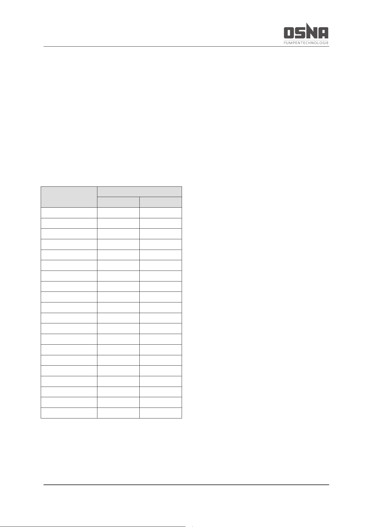
Conditions for measurement:
· Distance to pumping unit: 1 m
· Operation: Free of cavitation
· Motor: IEC standard motor
· Tolerance: ± 3 dB(A)
Drive power in kW
Noise emissions in dB(A)
1450 min-1
2900 min-1
0.75
50
58
1.1
53
62
1.5
55
62
2.2
56
63
3.0
58
65
4.0
60
66
5.5
64
70
7.5
65
71
11.0
68
73
15.0
69
74
18.5
69
74
22.0
70
75
30.0
71
75
37.0
72
76
45.0
73
77
55.0
73
79
75.0
74
81
90.0
74
82
110.0
75
83
132.0
76
84
Table 5: Sound pressure level
Low-noise motors can be provided if the expected noise values exceed the permitted limits.
Page 15
3 Layout and function
NMH/NMV High Pressure Centrifugal Pump 13
3 Layout and function
3.1 Labeling
3.1.1 Pump type labeling
This operating manual applies to the
NMH/NMV type series.
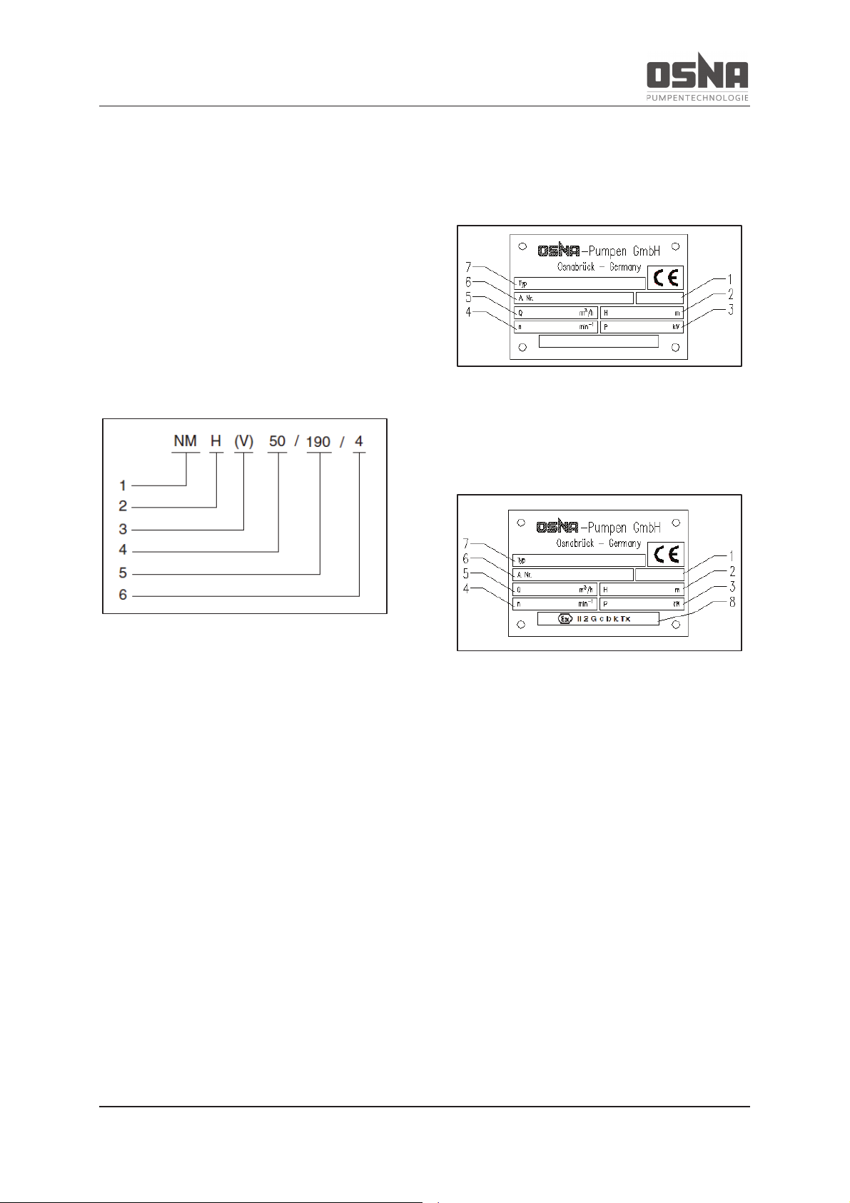
Model code:
Figure 1: Model code
Key:
1 Type series
2 Horizontal configuration
3 Vertical configuration
4 Nominal diameter of discharge nozzle
[mm]
5 Max. impeller diameter [mm]
6 Number of stages
3.1.2 Type plate
Standard configuration:
Figure 2: Standard version type plate
ATEX configuration:
Figure 3: ATEX version type plate
Key:
1 Year of production
2 Delivery head [m]
3 Power requirements [kW]
4 Speed [min-1]
5 Flow rate [m³/h]
6 Pump number
7 Pump type
8 ATEX protection class
Page 16

3 Layout and function
14 NMH/NMV High Pressure Centrifugal Pump
3.2 Scope of delivery of an
NMH/NMV high-pressure centrifugal
pump
The customer can order the pump:
- with a free shaft (NMH) or without motor
(NMV)
- as a complete unit, i.e. fully assembled on
base plate with drive motor, coupling and
coupling guard
Figure 4: Scope of delivery for NMH with free shaft
Figure 5: Scope of delivery for NMV without motor
Figure 6: Scope of delivery for NMH as complete unit
Figure 7: Scope of delivery for NMV as complete unit
Key:
1 Pump
2 Drive motor
3 Baseplate
4 Coupling
5 Coupling guard
6 Pump base
The scope of delivery corresponds to the
scope indicated in the order. Please check that
the delivery is complete upon receipt. Notify
the delivery company of any transport damage
immediately. Please also refer to our conditions of sale and delivery. If using other motor
brands, please ensure that the motors have
the following drive torques as a multiple of the
nominal torque.
3.3 General information
The NMH/NMV pump series are non selfpriming, multistage, high-pressure centrifugal
pumps in horizontal and vertical configuration.
The suction and discharge nozzles can be
installed at different stages of 90°.
The horizontal-configuration pumps are fitted
with anti-friction bearings. The verticalconfiguration pumps have one anti-friction
bearing (pressure side) and one plain bearing
(suction side).
Page 17
3 Layout and function
NMH/NMV High Pressure Centrifugal Pump 15
Both vertical and horizontal pumps can be
fitted with either an uncooled mechanical seal
or an uncooled gland packing.
3.4 Technical data
Main parameters:
NMH/NMV at speed = 1450 min-1
(gray cast iron)
Series
Delivery
head
Flow rate
H
max
Q
min
Q
opt
Q
max
m
m³/h
m³/h
m³/h
32
104
1.8
8.5
12
40
110
3.75
16.0
25
50
154
5.25
30.0
35
65
198
9.75
42.0
65
80
226
15.0
65.0
100
Table 6: Main parameters at 1450 rpm
NMH/NMV at speed = 2900 min-1
(gray cast iron)
Series
Delivery
head
Flow rate
H
max
Q
min
Q
opt
Q
max
m
m³/h
m³/h
m³/h
32
336
3.3
16.5
22
40
362
6.6
30.0
44
50
381
10.1
50.0
67
65
400
16.5
80.0
110
80
400
27
135.0
180
Table 7: Main parameters at 2900 rpm
Flange:
NMH/NMV
series
Suction side
Pressure side
NPS
PN
NPS
PN
32
50
40
32
40
40
65
40
40
40
50
80
40
50
40
65
100
40
65
40
80
125
40
80
40
Table 8: Pump series' flange sizes
Drive unit:
NMH: 50 and 60 Hz electric motor, diesel
motor or turbine
NMV: Electric motor with IEC flange, V1 con-
figuration or hydraulic motor with special flange
3.5 Operating point
In order to reach the required operating point,
it may be necessary to fit the pump with two
different sizes of impeller blade. For this reason, please provide the impeller blade diameter or position on the shaft when ordering
spare parts (1st, 2nd impeller, etc., beginning
at the suction side of the pump).
Please always indicate the pump type and
order number when ordering spare parts, or in
the event of any queries.
3.6 Minimum output rates
Pump tempe
rature
range
Minimum output rate
at design point
–
10 to +100 °C
15% of Q
opt
+100 to +140°C
20% of Q
opt
Table 9: Minimum output rates with closed
shut-off valve
Page 18
3 Layout and function
16 NMH/NMV High Pressure Centrifugal Pump
3.7 Functional and operating ele-
ments
Shaft wearing sleeve:
Shaft
wearing
sleeve
NMH
NMV
Uncooled gland
packing
Up to 110 °C
Up to 100 °C
Uncooled mechanical seal
Up to 140 °C
Up to 140 °C
Table 10: Maximum authorized operating temperature
at the shaft seal
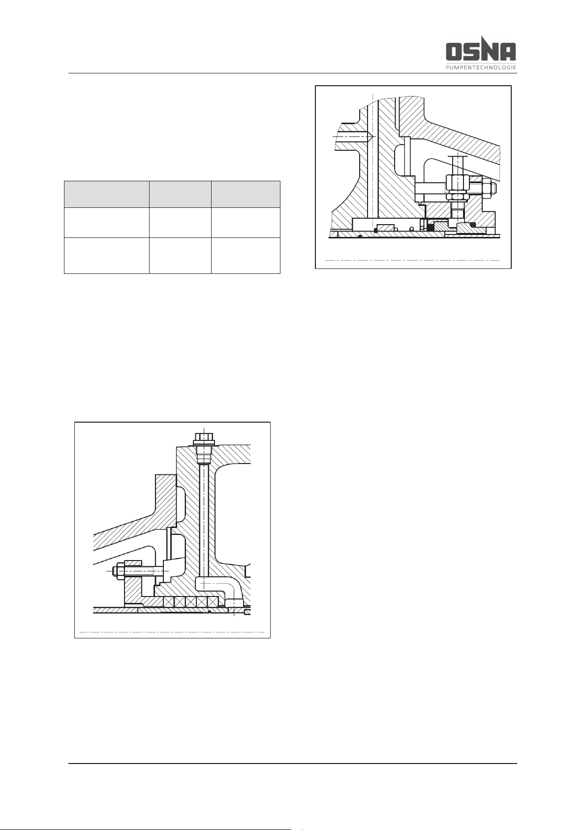
The pumps can be fitted with gland packing or
mechanical seal as required.
Gland packing consists of a number of compression-molded rings in a stuffing box. Gland
packings can be adjusted by hand with tools.
Figure 8: Gland packing
Mechanical seals are mechanical shaft seals
with internal flushing of the rotating seal rings
(self-adjusting).
Figure 9: Mechanical seal
The technical dry running properties of gland
packing and mechanical seals are extremely
limited. For this reason, avoid dry running.
Ensure that the pump is vented before commissioning.
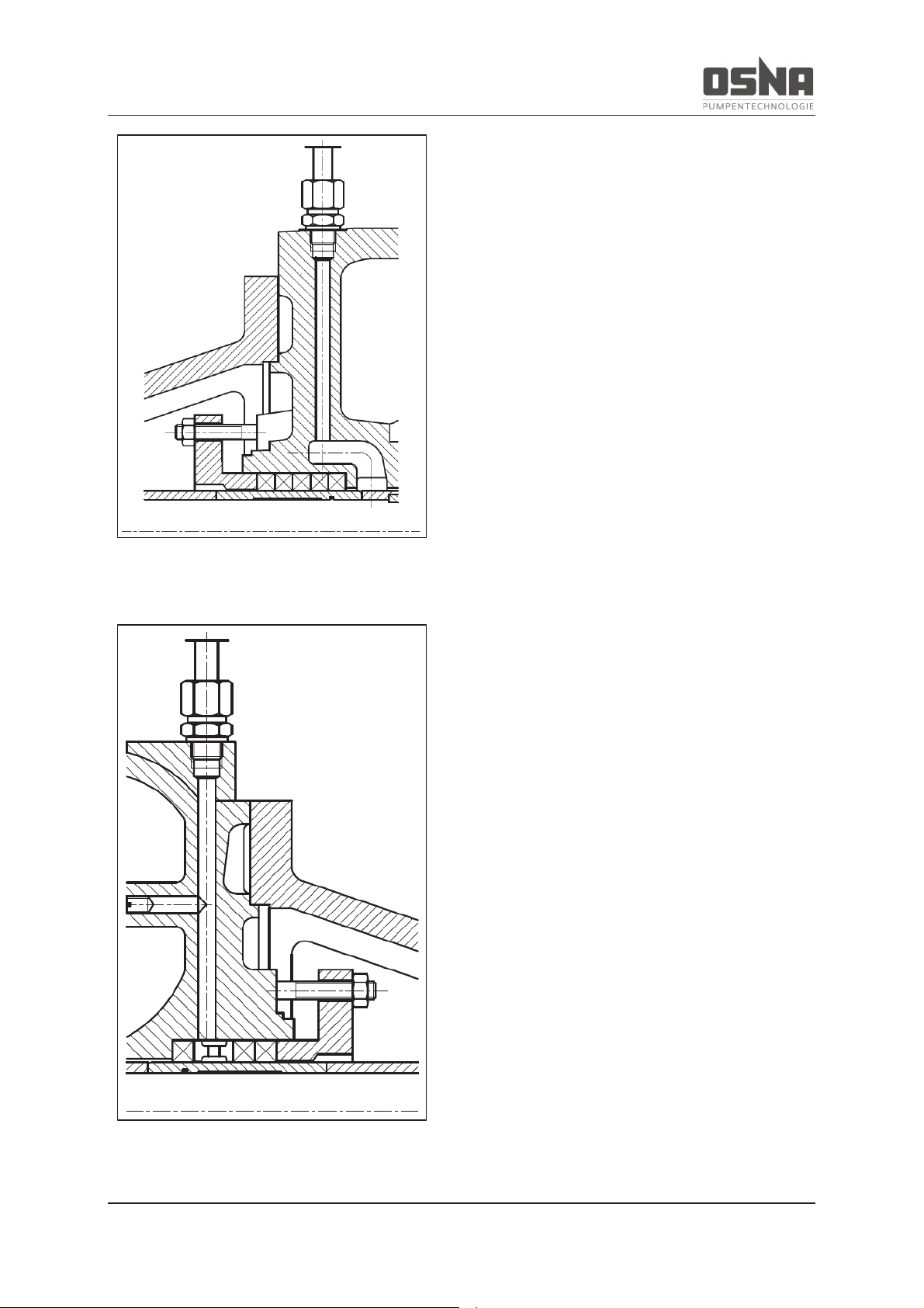
3.8 Auxiliary operating systems
When blocking, the pressure of the sealing
medium is higher than that of the pumping
medium.
Example: Pumping media that crystallize or
are laden with solid particles, and can therefore damage the seal over time.
Page 19
3 Layout and function
NMH/NMV High Pressure Centrifugal Pump 17
Figure 10: Pressure-side external flushing
connection (optional)
Figure 11: Suction-side external flushing
connection (optional)
Page 20
4 Transport and intermediate storage
18 NMH/NMV High Pressure Centrifugal Pump
4 Transport and intermediate
storage
4.1 Transport
Weight information (→ Other valid docu-
ments)
4.1.1 Unpacking and checking the de-
livery condition
1. Check that the delivery is complete
upon receipt.
2. Unpack the pump/unit upon delivery
and check for transport damage.
3. Notify the delivery company of any
transport damage immediately.
4. Dispose of the packaging material in
line with the applicable local regulations.
4.1.2 Lifting
Transport the pumps carefully and secure
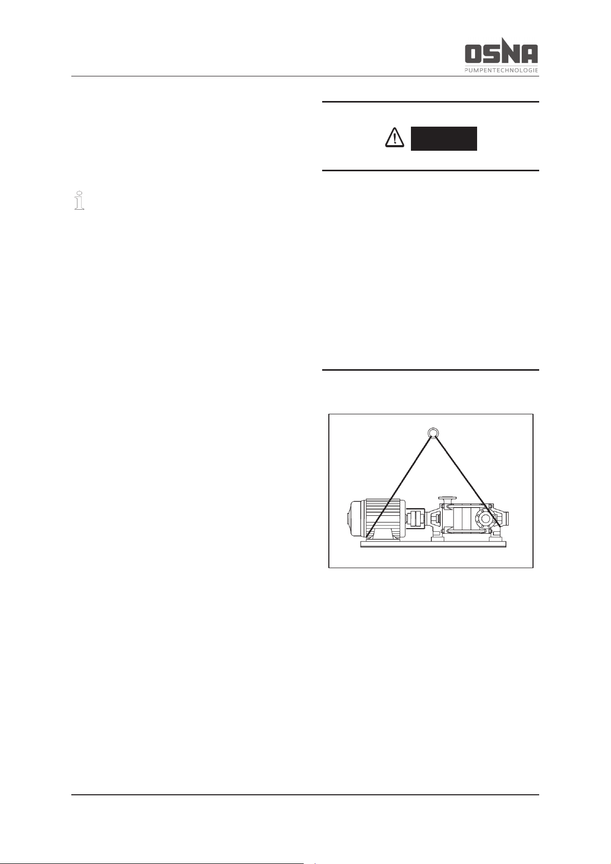
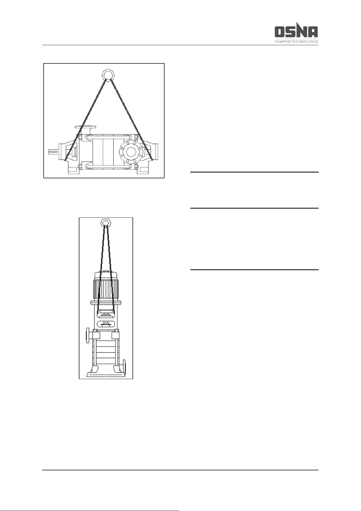
them to prevent damage. If using a horizontal
pump, transport the entire unit using ropes as
shown in Figure 12 (pg 18) (do not secure the
ropes on the motor eyelets). Transport vertical
pumps as shown in Figure 14 (pg 19).
DANGER
Risk of death or crushed limbs from falling
transported goods!
► Choose lifting equipment that is suitable for
the total weight to be transported.
► Secure the lifting equipment according to
the following images.
► Do not stand under suspended loads.
Figure 12: Lifting an NMH centrifugal pump (unit)
Page 21
4 Transport and intermediate storage
NMH/NMV High Pressure Centrifugal Pump 19
Figure 13: Lifting an NMH centrifugal pump
(free shaft end)
Figure 14: Lifting an NMV centrifugal pump
4.2 Intermediate storage
Ensure during intermediate storage that the
pump is not exposed to any weather conditions
for a long period of time. If the pump is decommissioned for a longer period of time (approximately 2 to 3 months), ensure that it is
fully drained. (→ 6.2 Decommissioning, pg 39)
4.3 Storage
NOTICE
Material damage due to incorrect storage!
► Ensure that the pump is correctly
stored.
1. Close all openings with blank flanges,
blind plugs or plastic covers.
2. Ensure that the storage area meets
the following conditions:
– dry
– free of frost
– free of vibrations
3. Rotate the shaft once per month by
several rotations.
Page 22
4 Transport and intermediate storage
20 NMH/NMV High Pressure Centrifugal Pump
NOTICE
Damage to bearings due to high water
pressure or splashing water!
► Do not use water jets or steam jet cleaners
to clean the bearing areas and motor.
NOTICE
Damage to seals due to incorrect cleaning
agent!
► Ensure that the cleaning agent does not
corrode the seals.
1. Choose the cleaning agent according
to the area of use.
2. Dispose of preservatives in line with
the applicable local regulations.
3. When storing for longer than 6
months:
– Check all elastomers (round seals,
shaft seal rings, gaskets and gland
packing) for elasticity, and replace
if necessary.
4.4 Disposal
Plastic parts may be contaminated by toxic
or radioactive pumping media. If this is the
case, cleaning is not sufficient.
WARNING
Risk of poisoning and environmental damage from pumping medium!
► Use personal protective equipment when
performing work on the pump.
► Before disposing of the pump:
– Collect any remaining pumping
medium in the pump, and dispose
of it in line with the locally valid
regulations.
– Neutralize any pumping medium
residues in the pump.
► Dispose of the pump in line with the appli-
cable local regulations.
Page 23
5 Assembly and installation
NMH/NMV High Pressure Centrifugal Pump 21
5 Assembly and installation
5.1 Preparing for installation
NOTICE
Material damage due to contamination!
► Only remove covers, transport caps and
sealing caps immediately before connecting
the pump to the pipelines.
CAUTION
Ensure compliance with all safety specifications during installation and operation.
1. Ensure that the required ambient conditions are met (à 5.1.1 Preparing the
installation location, pg 21)
2. Please consult the manufacturer when
installing at altitudes over 1000 m
above mean sea level.
5.1.1 Preparing the installation location
► Ensure that the installation location meets
the following conditions:
– pump is freely accessible from all
sides
– sufficient space for installing/removing
piping, as well as for maintenance and
repair work, in particular for installing/removing the pump and motor
– no effects from external vibrations on
the pump (bearing damage)
– protection against frost
Temperature
[°C]
Relative humidity [%]
Installation
altitude
above
mean sea
level [m]
long term
short term
-10 to 40
≤ 85
≤ 100
≤ 1000
Table 11: Ambient conditions
5.1.2 Preparing the base surface and
foundations
► Ensure that the base surface and founda-
tions meet the following conditions:
– level
– clean (no oils, dust or other contami-
nations)
– foundations can support the weight of
the pump unit and all operating forces
– stability of the pump unit ensured
Page 24
5 Assembly and installation
22 NMH/NMV High Pressure Centrifugal Pump
5.1.3 Removing the preservative
Only necessary for preserved pump.
WARNING
Risk of poisoning from preservatives and
cleaning agents in the food and drinking
water area!
► Only use cleaning agents that are compati-
ble with the pumping medium.
► Remove the preservative completely.
NOTICE
Damage to bearings due to high water
pressure or splashing water!
► Do not use water jets or steam jet cleaners
to clean the bearing areas.
NOTICE
Damage to seals due to incorrect cleaning
agent!
► Ensure that the cleaning agent does not
corrode the seals.
1. Choose the cleaning agent according
to the area of use.
2. Dispose of preservatives in line with
the local regulations.
3. If storing for longer than 6 months:
- Replace elastomers made from
EPDM.
- Check all elastomers (round seals,
shaft seals) for proper elasticity
and replace if necessary.
Page 25
5 Assembly and installation
NMH/NMV High Pressure Centrifugal Pump 23
5.2 Installation
5.2.1 Installing the pump
Prior to installation, remove the packaging (if
present) and check the pump for any transport
damage. Ensure that the installation area is
dry and free of frost.
CAUTION
Do not operate the pump in areas where
there is a risk of explosion. Ensure that the
pump is installed and connected in line
with the local regulations.
We recommend installing the pump on a
noise-insulating base, in order to prevent
transmission noises to parts of the building.
Provide an outlet for leakage fluid during
maintenance work.
During installation, align the entire unit on the
foundation using a spirit level (on
shaft/discharge nozzle). Maintain the distance
between the coupling halves according to the
installation plan. Always insert bearing plates
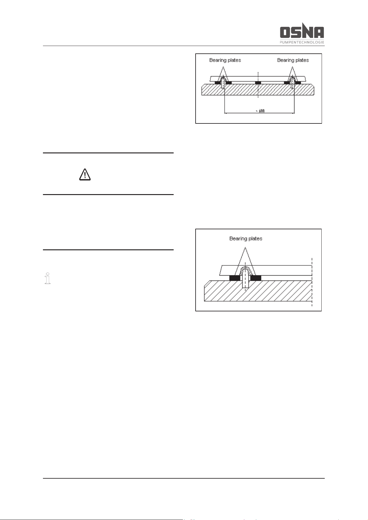
on the left and right side next to the mounting
material between the base plate/base frame
and the foundation. Provide additional bearing
plates if the distance between the mounting
materials is greater than 800 mm. Ensure that
all bearing plates sit solidly. Base plates with a
width greater than 400 mm must be filled out
after mounting with a vibration-dampening
mortar up to the upper edge of the frame.
Figure 15: Mounting material for complete units
If the pump and motor are delivered separately, place the pump onto the foundation without
the motor, align using a precision spirit level
and secure. For alignment purposes, always
insert bearing plates on the left and right side
next to the mounting material between the
pump base and the foundation. Ensure that all
bearing plates sit solidly.
Figure 16: Mounting material for pump with
open shaft end
If the pump has two or more anchoring points
(see overall diagram or installation plan), ensure that they are not strained axially or radially.
Page 26
5 Assembly and installation
24 NMH/NMV High Pressure Centrifugal Pump
NOTICE
Material damage due to strain on the base
plate!
► Place and secure the base plate to the
foundation as follows.
ü Aids, tools, material:
(not included in delivery)
- Foundation bolts
- Steel shims
- Mortar casting compound, vibra-
tion free
- Spirit level
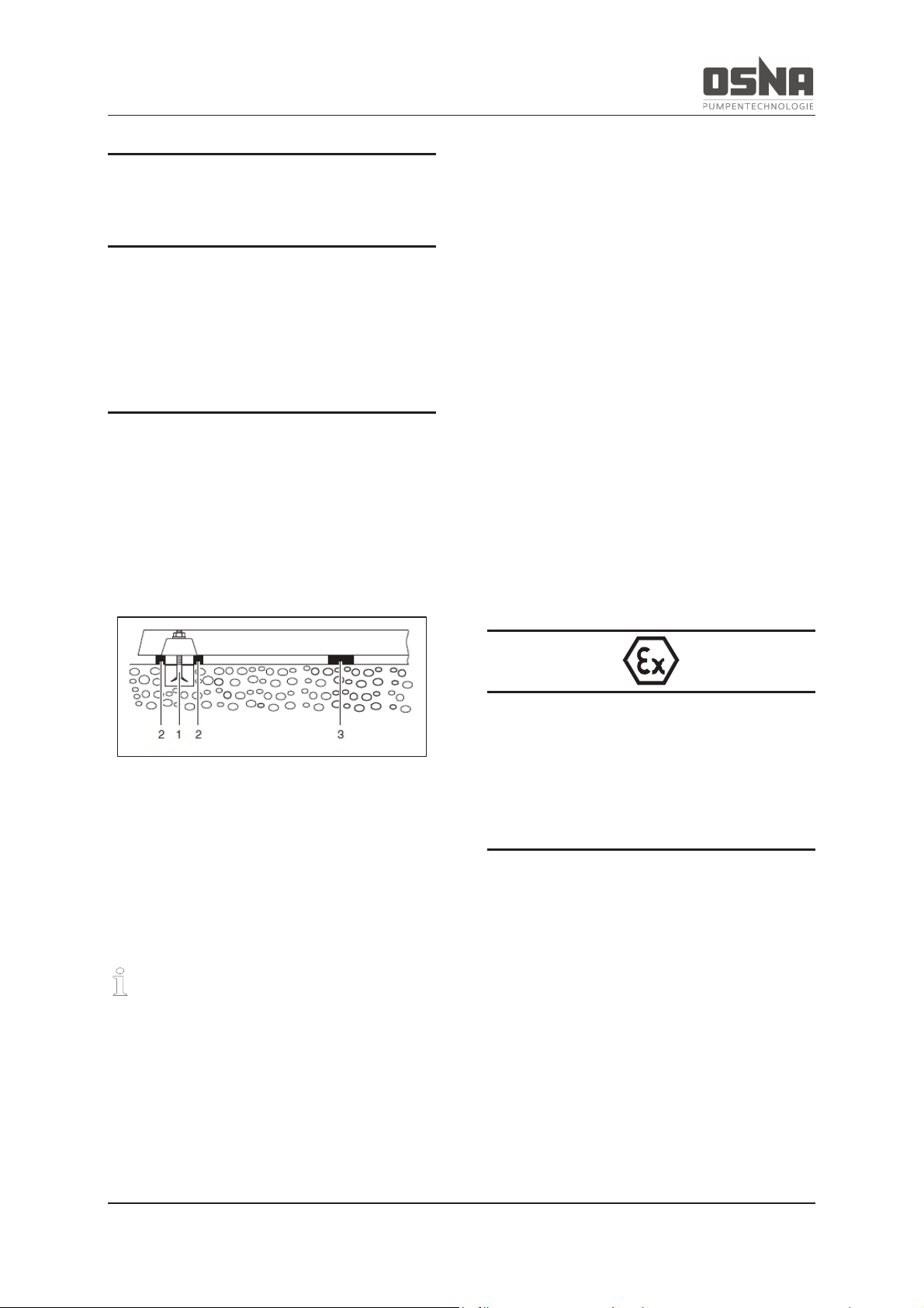
Figure 17: Aligning the base plate
1. Lift the pump unit (à 4.1.2 Lifting, pg
18).
2. Insert the foundation screws from below into the fastening holes on the
base plate.
If using adhesive anchors, observe the
manufacturer's information.
3. Place the pump unit on the foundation,
inserting the foundation screws into
the prepared anchoring holes as you
do so.
4. Align the pump unit to the required
height and system dimensions as follows using steel shims:
- Use one steel shim (2) to the left
and right of each foundation screw
(1).
- If the distance between the anchoring holes is greater than 700
mm, add additional steel shims (3)
on each side of the base plate in
the middle.
5. Ensure that the base plate and the
steel shims lie flat.
6. Check the maximum permitted height
deviation (1 mm/m) laterally and longitudinally using a machine spirit level.
7. Repeat the process until the baseplate
is correctly aligned.
The use of pumps in ATEX zones is subject
to additional requirements!
à 9.1.3 Installation and connection, pg 57
Take the following additional measures
when operating pumps in ATEX zones
· Only use touch guard elements (e.g.
coupling guard) made from electrically
conductive materials.
· Secure the grub screw for connecting
the coupling halves (e.g. using Loctite
medium strength)
Page 27
5 Assembly and installation
NMH/NMV High Pressure Centrifugal Pump 25
· Remove any metal shavings and dirt
residues from all touch guard elements.
· The motor must meet the require-
ments of the area at risk of explosion
(group, category).
· Install a soft-closing non-return valve
between the discharge nozzle and the
shut-off valve to prevent the backflow
of pumping medium after the pump is
switched off.
· If using a frequency inverter, please
consult the manufacturers of the pump
and the frequency inverter beforehand.
5.2.2 Securing the pump unit
Filling out the base plate with a mortar
casting compound improves the insulation
properties.
1. Fill out the anchoring holes with mortar
casting compound.
2. Once the mortar casting compound
has set, screw the base plate tightly at
three points using the specified tightening torque.
3. Before tightening the remaining
screws, compensate for any unevenness in the mounting surface using
spacers on each screw.
4. Check the pump unit for tensions using a straitedge.
5. Fill out the inside of the base plate if
provided. Knock on the base plate to
prevent cavities.
5.2.3 Assembling the motor
Only necessary if the pump unit is completed at the installation location.
Ensure that the shaft is cleaned of anti-rusting
agent, and that both coupling halves are
pushed onto the shaft. We recommend checking the direction of rotation as per section 6.1.3
(pg 37) before assembling the motor.
CAUTION
Incorrect direction of rotation on the pump
can lead to damage to the mechanical seal
and a reduction in performance. Please
observe the direction of rotation arrow on
the pump.
NOTICE
Incorrectly aligned shafts can cause increased wear on the bearings, seal rings,
shaft seals and elastic coupling elements.
They can also cause increased noise when
the unit is running.
Place the motor on the base plate. Compensate for the height difference between the
shafts precisely using shims. The distance
between the shaft ends should not exceed 3
mm.
Page 28
5 Assembly and installation
26 NMH/NMV High Pressure Centrifugal Pump
5.3 Fine alignment of the coupling
The unit is correctly aligned when a ruler
placed across both halves of the coupling is
the same distance from the respective shaft at
all points around the circumference. Do not
forget to turn the measurement point by hand.
Furthermore, both halves of the coupling must
be the same distance from each other at all
points around the circumference. Check this
using a tracer or gauge.
NOTICE
Material damage due to shocks and impacts!
► Do not tilt the two halves of the coupling
when pushing them onto the shaft.
► Avoid knocking the pump components.
The central axes of the pump and motor are
aligned according to their:
a) position
b) direction
Achieve both of these conditions by inserting
or removing shims of different thicknesses
under the pump or motor feet as appropriate.
Afterwards, tighten the fastening screws of the
pump and motor.
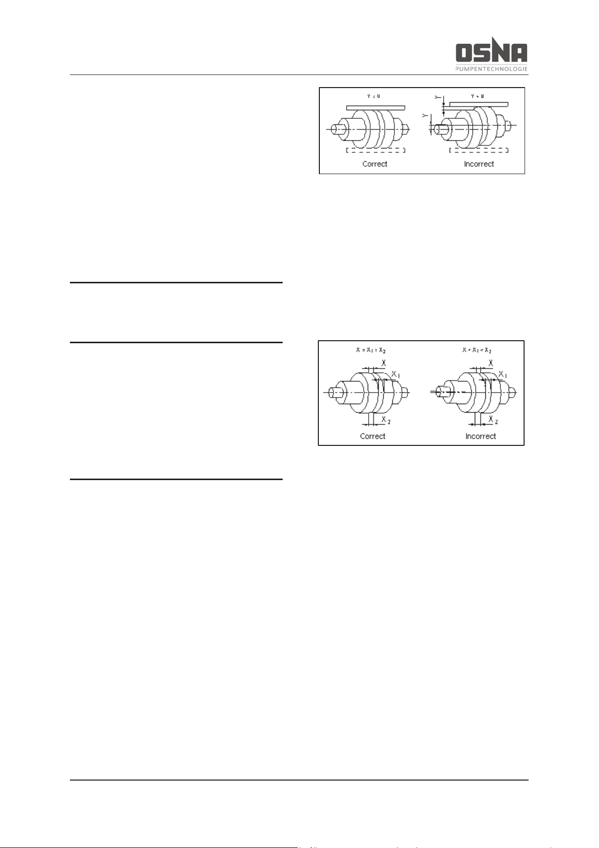
a) Position
A ruler placed on the coupling must lie
flat on both halves, offset by 90°,
around the circumference (à Figure
18, pg 26).
Figure 18: Positional alignment of the shafts
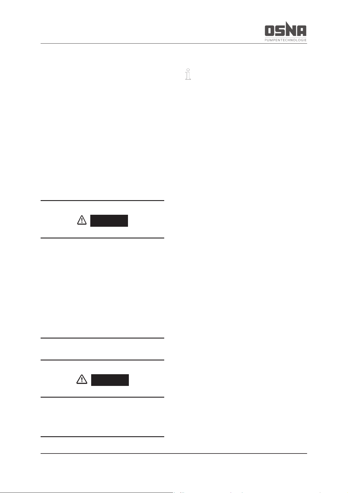
b) Direction
The axial distance (x) between the
halves of the coupling must be equal
around the entire circumference. Set
coupling distance x to 4 - 5 mm, and
secure against axial displacement (à
Figure 19, pg 26).
Figure 19: Directional alignment of the shafts
5.3.1 Horizontal configuration
1. Apply a very thin layer of molybdenum
disulfide (e.g. Molykote) to the shaft
ends on the pump and motor.
2. Insert the keys.
3. If using fitting device, remove the rubber buffer and heat the two halves of
the coupling to around 100 °C.
4. Push the pump-side and motor-side
coupling halves onto the shaft until the
shaft end is flush with the coupling
hub. When assembled, maintain a distance of 4 - 5 mm between the coupling halves.
Page 29
5 Assembly and installation
NMH/NMV High Pressure Centrifugal Pump 27
5. Tighten the grub screws on both coupling halves.
6. Place suitable bearing plates beneath
the motor/pump until the ends of the
respective shafts are flush.
7. Insert the motor screws, but do not
tighten (à 5.4 Aligning the motor, pg
28).
8. Mount the coupling guard.
The coupling guard must always be mounted
after aligning the coupling.
DANGER
Risk of death due to rotating parts!
► Use personal protective equipment
when performing work on the pump.
► Prevent the keys from being slung
away when checking the direction of
rotation.
► Ensure sufficient clearance to rotating
parts.
DANGER
Never operate the pump without the coupling guard.
5.3.2 Vertical configuration
Vertical pumps are always delivered with a
complete coupling (assembled on the
pump).
1. Apply a very thin layer of molybdenum
disulphide (e.g. Molykote) to the shaft
ends on the pump.
2. Insert the keys.
3. If using fitting device, remove the rubber buffer and heat the two halves of
the coupling to around 100 °C.
4. Push the pump-side and motor-side
coupling halves onto the shaft until the
shaft end is flush with the coupling
hub. When assembled, maintain a distance of 4 - 5 mm between the coupling halves.
5. Tighten the grub screw on the motorside coupling half.
6. Place the motor on the pump. Ensure
here that both halves of the coupling fit
securely.
7. Secure the motor to the pump with
screws.
The coupling guard must always be mounted
after aligning the coupling.
Page 30
5 Assembly and installation
28 NMH/NMV High Pressure Centrifugal Pump
DANGER
Risk of death due to rotating parts!
► Use personal protective equipment
when performing work on the pump.
► Prevent the keys from being slung
away when checking the direction of
rotation.
► Ensure sufficient clearance to rotating
parts.
DANGER
Never operate the pump without the coupling guard.
5.4 Aligning the motor
Horizontal configuration only. Alignment
options:
- with shims
- with adjustment screws
5.4.1 Aligning the motor with shims
1. Align the motor so that the two halves
of the coupling are precisely flush, using shims if necessary.
2. Check the alignment of the motor to
the pump.
3. If the height displacement persists, repeat the alignment process.
4. Afterwards, tighten the motor screws.
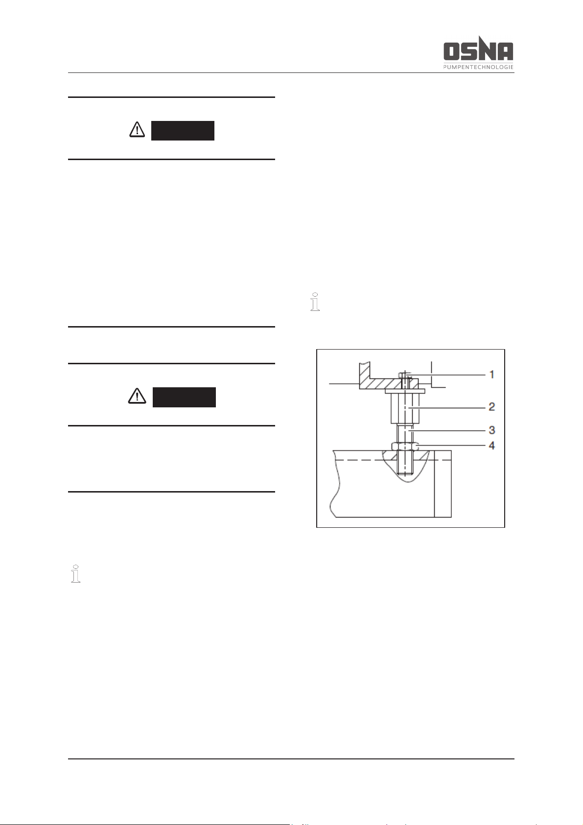
5.4.2 Aligning the motor with adjustment screws
Observe the spindle's angle of rotation
when adjusting the adjustment screws.
Figure 20: Aligning the motor with adjustment screws
1. Determine the angle required for the
wrench rotations for the measured
height displacement.
2. Loosen the hexagon head bolt (1)
Page 31
5 Assembly and installation
NMH/NMV High Pressure Centrifugal Pump 29
3. Perform the following steps on all adjustment screws (3):
- Hold the adjustment screw (3) at
the hexagon head (2) and loosen
the lock nut (4).
- Adjust the adjustment screw (3) by
the required angle.
- Hold the adjustment screw (3) at
the hexagon head (2) and tighten
the lock nut (4).
4. Tighten the hexagon head bolt (1).
5. Check the alignment.
6. If the height displacement persists, repeat the alignment process.
7. Afterwards, tighten the motor screws.
5.5 Planning pipelines
5.5.1 General
Determine the nominal widths of the pipelines,
taking the local conditions into account. To
keep flow losses to a minimum, avoid sudden
constrictions and sharp bends. Route pipelines
free of tension and pressure tight. Install them
in a way that prevents forces and torques being transferred to the pump. Never use the
pump as an anchor point for the pipeline.
Fit the suction pipe rising to the pump and the
inlet pipe declining to the pump, in order to
prevent the formation of air bubbles. Support
the pipes immediately before the pump, and
connect without tension. Ensure that the
weight of the pipes does not strain the pump. If
using short pipes, the nominal widths must be
at least equal to those of the pump connections. If using long pipelines, determine the
cost-effective nominal width on a case-by-case
basis.
CAUTION
Before commissioning new systems, the
tanks, pipelines and connections must be
thoroughly cleaned, flushed and blown
through. Welding beads, scales and other
contaminations often only fall off after a
longer period of time. Ensure that they are
kept away from the pump by fitting a
strainer in the suction pipe.
Taper pieces to larger nominal widths should
have an extending angle of approx. 8° to prevent increased pressure losses. Install check
valves and shut-off devices depending on the
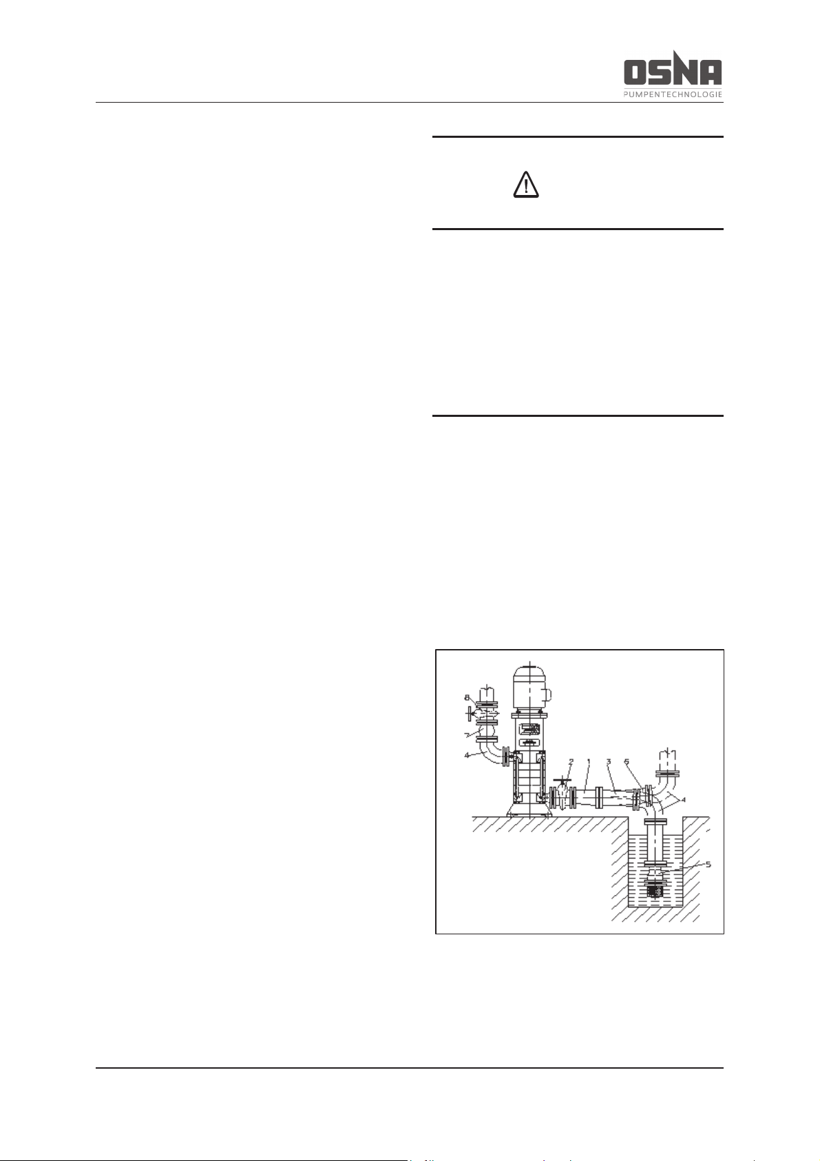
type of system and pump (à Figure 21, pg
29).
Take appropriate measures to compensate
any expansions of the pipelines caused by
temperature influences, in order to avoid
straining the pump with forces and torques.
Figure 21: Functional and operating elements
Page 32
5 Assembly and installation
30 NMH/NMV High Pressure Centrifugal Pump
Key:
1 Eccentric taper piece
2 Shut-off valve
3 Suction pipe
4 Elbow
5 Foot valve with inlet strainer
6 Inlet pipe
7 Check valve
8 Control fitting
* not included in delivery
Control fitting
(à Figure 21, pg 29, 8)
A control fitting is always required to regulate
the pump power and block the pipeline during
assembly work.
Check valve
(à Figure 21, pg 29, 7)
A check valve is always required to protect the
pump.
Monitoring fitting
Monitoring fittings are required to monitor the
suction and inlet pressure. Monitoring valves
help monitor the operating data.
Flushing the shaft seal
If the pumping medium is contaminated, we
recommend flushing the shaft seal. This pre-
vents contamination from penetrating the shaft
seal, and therefore also prevents excessive
wear.
Sealing and flushing fluid pressure
The pressure of sealing and flushing fluid
should always be 1 bar above the pump operating pressure.
Sealing the shaft seal
Sealing the shaft seal prevents air entry at high
suction heads.
Leak fluid (leakage)
Drain leak fluid using pipes or hoses.
Auxiliary pipes
Route auxiliary pipes according to their nominal connection values, provided that they are
not pressurized internally by the pump. The
connections on the pump are indicated. All
auxiliary pipes must have a control fitting and
non-return valve.
The use of pumps in ATEX zones is subject
to additional requirements!
à 9.1.3 Installation and connection, pg 57
Page 33
5 Assembly and installation
NMH/NMV High Pressure Centrifugal Pump 31
5.5.2 Avoiding contaminations in the
pipelines
1. Clean all pipeline components and fittings prior to assembly.
2. Ensure that gaskets do not protrude
inwards.
3. Remove any blank flanges, plugs, protective films and/or protective coatings
on flanges.
NOTICE
Material damage due to contamination in
the pump!
► Ensure that the pump is free of contamina-
tions.
5.5.3 Configuring supports and flange
connections
NOTICE
Material damage due to excessively high
forces and torques in the pipes acting on
the pump!
► Do not exceed the permitted values.
1. Calculate the forces in the pipeline and
observe all operating conditions:
- cold/warm
- empty/filled
- pressurized/unpressurized
- change in the flange position
2. Ensure that the pipeline supports have
permanent low-friction properties and
do not seize up due to corrosion.
5.5.4 Determining nominal widths
Keep the flow resistance as low as possible.
1. Set the nominal width of the suction
pipe to be greater than that of the suction nozzle.
2. Set the nominal width of the suction
pipe to be greater than that of the suction nozzle.
3. The flow rate may not exceed 1.5 m/s.
5.5.5 Determining pipeline lengths
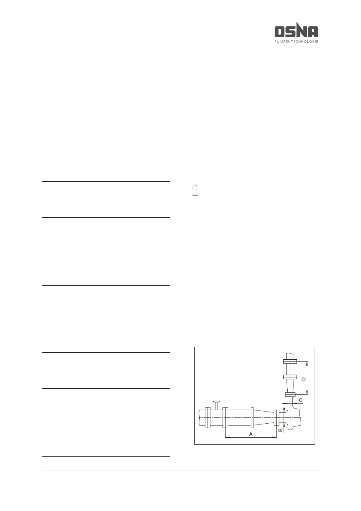
Figure 22: Recommended straight pipeline lengths
upstream and downstream of the pump
Page 34
5 Assembly and installation
32 NMH/NMV High Pressure Centrifugal Pump
A > 5x DNs
B DNs
C DNd
D > 5x DNd
Ensure compliance with the recommended
pipeline lengths when installing the pump.
Suction side: Shorter lengths are
possible, but this may limit the hydraulic
performance data.
Pressure side: Shorter lengths are
possible, but this may lead to increased
noise levels.
5.5.6 Optimizing changes in crosssection and direction
1. Avoid bend radii that are smaller than
1.5 times the nominal pipe width.
2. Avoid sudden changes to the crosssection along the pipeline.
5.5.7 Providing safety and monitoring
systems (recommended)
Preventing contamination
1. Install a filter in the suction pipe.
2. Install a differential pressure display
with contact manometer to monitor
contamination.
Preventing backflow
Install a non-return valve between the discharge nozzle and the shut-off valve to prevent
medium backflow after the pump is switched
off.
Enabling separation and blocking of the
pipelines
For maintenance and repair work.
1. Provide shut-off devices in the suction
and pressure pipe.
2. Recommended: Provide a drainage
mechanism.
Enabling measurement of operating conditions
1. Provide manometers in the suction
and pressure pipe to measure pressure.
2. Provide a torque measurement instrument on the motor side.
3. Provide a temperature measurement
instrument on the pump side.
5.6 Attaching the pipelines
5.6.1 Installing auxiliary pipelines
Observe the manufacturer information for
any auxiliary operating systems, if used.
Page 35
5 Assembly and installation
NMH/NMV High Pressure Centrifugal Pump 33
1. Install auxiliary pipelines to the auxiliary connections, sealed and without
tension (à Installation plan).
2. Prevent air pockets by routing the
pipelines rising to the pump.
5.6.2 Installing the suction pipe
1. Remove transport and sealing caps on
the pump.
2. Fit the filter in the suction pipe to prevent contamination.
3. Prevent air pockets by routing the
pipeline rising to the pump.
4. Ensure that the gaskets do not protrude inwards.
5. During suction operation, install a foot
valve in the suction pipe to prevent the
pump and suction pipe from emptying
when not in operation.
NOTICE
Always open the suction-side fitting when
operating the pump, and do not use it to
control the flow rate.
5.6.3 Installing the pressure pipe
1. Remove transport and sealing caps on
the pump.
2. Prevent air pockets by routing the
pipeline constantly declining to the
pump.
3. Ensure that the gaskets do not protrude inwards.
5.6.4 Checking for lack of tension in
the pipeline connection
ü Pipeline routed and cooled
1. Disconnect the connection flange of
the pipelines from the pump.
2. Check whether the pipeline can move
freely in all directions in the expected
area of expansion:
- Nominal width < 150 mm: by hand
- Nominal width > 150 mm: with
small lever
3. Ensure that the flanges are plane parallel.
4. Reconnect the connection flange of
the pipelines to the pump.
NOTICE
Material damage due to excessively high
forces and torques in the pipes acting on
the pump!
► Do not exceed the permitted values.
Page 36
5 Assembly and installation
34 NMH/NMV High Pressure Centrifugal Pump
5.7 Electrical connection
CAUTION
Electrical connection must be carried out
by a specialist electrician, in line with the
specifications of the local energy supplier
or the VDE.
DANGER
Risk of death from electric shock!
► Only allow work on the electrical systems to
be carried out by a qualified electrician.
► Ensure that the supply of electricity is
switched off and secured against reactivation when performing all maintenance work.
DANGER
Risk of death due to rotating parts!
► Use personal protective equipment when
performing work on the pump.
► Prevent the keys from being slung away
when checking the direction of rotation.
► Ensure sufficient clearance to rotating
parts.
5.7.1 Connecting the motor
Observe the manufacturer information for
the motor.
Only use approved motors when operating
pumps in ATEX zones!
Install a motor protection switch to protect the
motor. If using three-phase motors with stardelta switch, ensure that the switching points
between star and delta are timed very closely
together. Longer switching times can lead to
damage to the pump.
1. Connect the motor according to the
circuit diagram.
Page 37
5 Assembly and installation
NMH/NMV High Pressure Centrifugal Pump 35
2. Ensure that no danger arises due to
electrical energy.
3. Install an EMERGENCY STOP switch.
4. Adjust the time relay to the motor
power accordingly.
Adjusting the time relay with star-delta activation:
Motor power
Time relay setting
≤ 30 kW
3 s 30%
> 30 kW
5 s 30%
Table 12: Settings for the time relay when using three-
phase motors with star-delta switch
NOTICE
Material damage due to improper use of
three-phase motor with star-delta switch!
► Adjust the time relay according to the motor
power (à Table 12, pg 35).
5.7.2 Earthing the pump
Always earth pumps in ATEX zones!
· Ensure that motors, couplings and
monitoring devices provided by the
customer meet the specified category
and temperature class in the respective ATEX zone (à 9.1.2 Explosion
protection marking, pg 56).
· Only use touch guard elements (e.g.
coupling guard) made from electrically
conductive materials.
· The motor must meet the require-
ments of the area at risk of explosion
(group, category).
· If using a frequency inverter, please
consult the manufacturer of the pump
and the frequency inverter beforehand.
Earth the motor and the pump separately from
each other.
Figure 23: NMH earthing screws
Figure 24: NMV earthing screws
For information on measures for earthing the
motor, please refer to the manufacturer's documentation.
Page 38
6 Commissioning/decommissioning
36 NMH/NMV High Pressure Centrifugal Pump
6 Commissioning/
decommissioning
6.1 Commissioning
6.1.1 Determining the pump configuration
DANGER
Risk of explosion!
► Ensure that no pumps with gland packing
are used in areas at risk of explosion.
► Determine the pump configuration (à Or-
der data sheet)
Pump configurations relate to the type of
shaft seal or auxiliary operating system, for
example.
The use of pumps in ATEX zones is subject
to additional requirements!
à 9.1.4 Operation, pg 59
6.1.2 Filling the pump
ü Auxiliary operating system ready
ü Preservative removed
(à 5.1.3 Removing the preservative,
pg 22)
1. Fill the pump and suction pipe with
pumping medium.
2. Open the suction-side fitting.
3. Open the pressure-side fitting.
4. Open the auxiliary operating systems
(if present) and check for flow.
5. Ensure that all connections and joints
are sealed.
CAUTION
Check that there is enough water in the well
or feed tank.
Do not operate the pump without water. Dry
running can lead to damage to the pump.
Page 39
6 Commissioning/decommissioning
NMH/NMV High Pressure Centrifugal Pump 37
WARNING
Risk of poisoning or injury due to hazardous pumping media!
► Collect any escaping pumping medium
safely and dispose of in an environmentally
friendly way.
NOTICE
Material damage due to dry running!
► Ensure that the pump is properly filled.
6.1.3 Checking direction of rotation
CAUTION
Incorrect direction of rotation on the pump
can lead to damage to the mechanical seal
and a reduction in performance. Please
observe the direction of rotation arrow on
the pump.
The cast direction of rotation arrow on the
pump indicates the specified direction of rotation.
Before checking the direction of rotation, secure the pump against activation.
1. Decouple the motor from the pump.
2. Switch the motor on and immediately
off again.
3. Check whether the motor's direction of
rotation corresponds to the arrow on
the pump.
4. If the direction of rotation is different,
reverse this by swapping two phases.
5. Recouple the motor with the pump.
6. Mount the coupling guard.
DANGER
Risk of death due to rotating parts!
► Use personal protective equipment when
performing work on the pump.
► Prevent the keys from being slung away
when checking the direction of rotation.
► Ensure sufficient clearance to rotating
parts.
After checking the direction of rotation, ensure
that all safety and protective mechanisms are
reinstalled and reactivated.
Page 40
6 Commissioning/decommissioning
38 NMH/NMV High Pressure Centrifugal Pump
DANGER
Never operate the pump without the coupling guard.
6.1.4 Starting the pump
Pump correctly installed and connect-
ed
Motor correctly installed and connect-
ed
Motor correctly installed and aligned
All connections established, sealed
and free of tension
ü Any auxiliary operating systems ready
All safety mechanisms installed and
function tested
Pump correctly prepared, filled and
vented
DANGER
Risk of injury due to running pump!
► Do not touch the running pump.
► Do not perform any work on the running
pump.
DANGER
Risk of poisoning or injury due to spurting
pumping medium!
► Use personal protective equipment when
performing work on the pump.
NOTICE
Material damage due to dry running!
► Ensure that the pump is properly filled.
Page 41
6 Commissioning/decommissioning
NMH/NMV High Pressure Centrifugal Pump 39
NOTICE
Open the suction-side fitting, and do not
use it to control the flow rate. Do not close
the pressure-side fitting!
Do not open the pressure-side fitting above the
operating point (à 3.6 Minimum output rates,
pg 15).
0.1 MPa = 1 bar ≈ 10 m
1. Open the suction-side fitting.
2. Close the pressure-side fitting.
3. Switch on the motor and ensure that it
runs quietly.
4. Once the motor has reached its nominal speed, slowly open the pressureside fitting until the operating point is
reached.
5. Ensure a temperature increase of < 50
°C/h if using the pump with hot pumping medium.
6. After the first pressure and temperature loads, check whether the pump is
tight.
7. If using hot pumping media, switch the
pump off briefly when at operating
temperature, check the coupling
alignment and realign the motor if
necessary (à 5.4 Aligning the motor,
pg 28).
8. Set a slight leakage on the gland pack-
ing, if present (à 6.5.2 Gland packing,
pg 42).
6.2 Decommissioning
DANGER
Risk of injury due to hot pump components!
► Use personal protective equipment when
performing work on the pump.
DANGER
Risk of injury due to running pump!
► Do not touch the running pump.
► Do not perform any work on the running
pump.
Page 42
6 Commissioning/decommissioning
40 NMH/NMV High Pressure Centrifugal Pump
WARNING
Risk of poisoning or injury due to hazardous pumping media!
► Use personal protective equipment when
performing work on the pump.
► Take the following measures in the event of
operating interruptions:
Flow medium
behavior
Duration of operating interruption (depending on pr
o-
cess)
short
long
Solid components settle
► Flush
pump.
► Flush
pump.
Solidified/frozen,
non
-corrosive
► Heat or
drain pump
and containers.
► Drain pump
and containers.
Solidified/frozen,
corrosive
► Heat or
drain pump
and containers.
► Drain pump
and containers.
► Apply preservative to
pump and
containers.
Remains fluid,
non-corrosive
– –
Remains fluid,
corrosive
–
► Drain pump
and containers.
► Apply preservative to
pump and
containers.
Table 13: Measures depending on the behavior of
the pumping medium
Pump to be
Measure
Shut down for
longer period
► Take measures according to the
pumping medium
Drained
► Close suction and pressure-side
fittings.
Disassembled
► Deactivate the motor and secure against unauthorized reactivation.
Put into storage
► Observe the storage measures
(→
4.3 Storage, pg 19).
Table 14: Measures in the event of
operational interruption
Drain the pump completely if shutting down for
a longer period (approx. 2 - 3 months), or if
there is a danger of frost.
NOTICE
This work must be carried out by a specialist service provider.
CAUTION
Disconnect the pump from the electricity
supply if shutting down for a longer period.
Page 43
6 Commissioning/decommissioning
NMH/NMV High Pressure Centrifugal Pump 41
6.2.1 Switching off the pump
1. Pressure-side fitting closed (recommended)
2. Switch off the motor.
3. Check all tie bolts and tighten if necessary.
6.2.2 Draining the pump and protecting
against frost
The pump must be drained if there is a danger
of frost. A pump that remains empty over a
longer period must be preserved.
6.3 Recommissioning
CAUTION
The pump must move easily for recommissioning.
Check that the pump moves easily before recommissioning.
If the pump was preserved after decommissioning, flush it thoroughly before recommissioning.
Perform all further work steps in line with 6.1
Commissioning, pg 36.
Take the following measures before recommissioning following operating interruptions of
> 1 year:
Shut down
time
Measure
> 1 year
► Check visually for leaks
> 2 years
Replace elastomer seals
(gaskets, round seals, shaft seal
rings and gland packings).
► Replace anti-friction bearings.
Table 15: Measures following longer shut down times
6.4 Operating the stand-by pump
ü Stand-by pump filled and vented
Operate the stand-by pump at least once
per week.
1. Open the suction-side fitting fully.
2. Open the pressure-side fitting as far as
required for the stand-by pump to
reach operating temperature and be
evenly warmed through (à 6.1.4 Starting the pump, pg 38).
Page 44
6 Commissioning/decommissioning
42 NMH/NMV High Pressure Centrifugal Pump
6.5 Shaft seal
6.5.1 Mechanical seal
NOTICE
Material damage due to dry running!
► Ensure that the pump is properly filled.
Mechanical seals are self-adjusting mechanical shaft seals that require no maintenance.
The mechanical seal must never run dry. Ensure therefore that the pump is filled.
Do not reinstall mechanical seals after removing them for inspection or maintenance. Replace them with new seals, or relap the contact
surface.
6.5.2 Gland packing
Gland packing consists of a number of compression-moulded rings in a stuffing box.
Gland packings can be adjusted by hand with
tools.
WARNING
Excessive tightening places too much tension on the packing rings. This leads to
wear and ultimately loss of tightness in the
stuffing box.
Replace the gland packing if the leaks in the
stuffing box persist. Check at the same that the
shaft wearing sleeves are in a good condition.
Any worn or scored shaft wearing sleeves can
lead to premature destruction of the packing.
NOTICE
Material damage due to dry running!
► Ensure that the pump is properly filled.
Page 45
7 Maintenance and repair
NMH/NMV High Pressure Centrifugal Pump 43
7 Maintenance and repair
7.1 General information
We can provide trained customer service
technicians for assembly and repair work.
Please present proof of the conveyed
goods upon request.
(DIN safety data sheet or clearance certificate)
DANGER
Risk of injury due to hot pump components!
► Use personal protective equipment when
performing work on the pump.
DANGER
Risk of injury due to running pump!
► Do not touch the running pump.
► Do not perform any work on the running
pump.
WARNING
Risk of poisoning or injury due to hazardous pumping media!
► Use personal protective equipment when
performing work on the pump.
Ensure that the pump runs smoothly and quietly at all times. Maximum permitted room temperature 40 °C.
The mechanical seal displays only limited or
invisible leakage losses (in vapor form). It requires no maintenance.
The reserve pumps must be activated once
per week in order to ensure operational readiness. To do so, switch the reserve pumps on
and immediately off again. Monitor the function
of the additional connections.
The pump shaft of the NMV series is supported in the suction casing in a zero-maintenance
bearing shell made from PTFE graphite. The
pump shaft and motor shaft are connected
rigidly by means of a muff coupling.
Page 46

7 Maintenance and repair
44 NMH/NMV High Pressure Centrifugal Pump
7.2 Operational monitoring
Ensure that the pump runs smoothly and quietly at all times. Maximum permitted room temperature 40°C. The bearing temperature may
be up to 50°C above the room temperature,
but may not exceed 90°C (measured externally
on the bearing housing).
NOTICE
Material damage due to dry running!
► Ensure that the pump is properly filled.
► Longer operation against a closed shut-off
device is not permitted.
If using a gland packing, this should drip slightly during operation. The gland may only be
tightened slightly. Leakage is always required
if using pure graphite packing rings. If leakage
is too high after a longer period of operation,
evenly tighten the nuts on the gland by 1/6 of a
rotation, and observe the leakage. If it is no
longer possible to adjust the gland, insert an
additional packing ring. It is generally not required to replace the entire packing.
If using mechanical seals, these display only
limited or invisible leakage losses (in vapor
form). They require no maintenance.
The reserve pumps must be activated once
per week in order to ensure operational readiness. To do so, switch the reserve pumps on
and immediately off again. Monitor the function
of the additional connections.
Replace the elastic elements of the coupling
promptly should you notice signs of wear over
time.
The bearings have a high-quality lithium-soap
grease. Under normal operating conditions,
this is sufficient for 15,000 operating hours or 2
years. If operating under unfavorable conditions, such as high room temperature, high
humidity, dusty air, aggressive industrial atmospheres, etc., check the bearings at an
earlier time, and clean and relubricate if necessary. When relubricating, use a lithium-soap
grease that is free of resins or acids, does not
become brittle and protects against rust.
Only half fill the cavities of the bearings with
grease. If necessary, you can also lubricate
the bearings with other soap-based greases.
As greases with different soap bases may not
be mixed, ensure that the bearings are thoroughly washed beforehand. Adjust the necessary relubrication intervals according to the
greases used.
1. Test at appropriate intervals:
- Maintenance of the minimum flow
rate
- Room temperature < 40 °C
- Temperature of the anti-friction
bearings < 90 °C
(measured on the bearing housing)
- No change in the normal operating
conditions
- Alignment of the coupling and
condition of the elastic elements
2. Please ensure the following for smooth
operation:
- No dry running
- No leaks
- No cavitation
- Gate valve open on suction side
- Filter free and clean
- Sufficient inlet pressure
- No unusual running noises or vi-
brations
- No unpermitted leakage on the
shaft seal
- Auxiliary operating systems function correctly
Page 47
7 Maintenance and repair
NMH/NMV High Pressure Centrifugal Pump 45
The use of pumps in ATEX zones is subject
to additional requirements!
à 9.1.4 Operation, pg 59
7.3 Maintenance
Service life of the anti-friction bearings in
the permitted operating range: > 2 years
Intermittent operation, high temperatures,
low viscosity and unfavorable ambient and
process conditions can reduce the service
life of the anti-friction bearings.
Mechanical seals wear naturally, although
this depends heavily on the respective operating conditions. It is therefore not possible to make any general statements about
the service life.
DANGER
Risk of death from electric shock!
► Only allow work on the electrical systems to
be carried out by a qualified electrician.
► Ensure that the supply of electricity is
switched off and secured against reactivation when performing all maintenance work.
DANGER
Risk of injury due to hot pump components!
► Use personal protective equipment when
performing work on the pump.
DANGER
Risk of injury due to running pump!
► Do not touch the running pump.
► Do not perform any work on the running
pump.
WARNING
Risk of poisoning or injury due to hazardous pumping media!
► Use personal protective equipment when
performing work on the pump.
Page 48
7 Maintenance and repair
46 NMH/NMV High Pressure Centrifugal Pump
The use of pumps in ATEX zones is subject
to additional requirements!
à 9.1.5 Maintenance and repair, pg 59
Ensure compliance with the following additional requirements when operating the
pump in an ATEX zone:
· Replace the anti-friction bearing in the
motor in line with the manufacturer
specifications.
· Replace the anti-friction bearing and
the plain bearing in the pump after
9000 operating hours.
· Check the following at appropriate in-
tervals (at least monthly):
- Motor and coupling in line with the
manufacturer's operating manual
- Surface temperature of the motor
and pump
- Any changes in running noise or
vibrations
- Deformation of the touch guard elements and distance to the hazardous parts
- Function of the monitoring devices
Always earth pumps in ATEX zones!
7.3.1 Anti-friction bearings and grease
lubrication
Relubricate after no more than 7500 operating hours or 1 year under normal operating
conditions.
1. Clean the anti-friction bearings thoroughly.
2. Use grease with the following properties:
- lithium soap base
- free of resins
- free of acids
- anti-rust effect
- non-drying
3. Only half fill the cavities in the antifriction bearings with grease.
7.3.2 Servicing the electric motors
CAUTION
Electrical connection must be carried out
by a specialist electrician, in line with the
specifications of the local energy supplier
or the VDE.
Page 49
7 Maintenance and repair
NMH/NMV High Pressure Centrifugal Pump 47
DANGER
Only perform the inspection when the system is switched off and secured.
DANGER
Risk of death from electric shock!
► Only allow work on the electrical systems to
be carried out by a qualified electrician.
► Ensure that the supply of electricity is
switched off and secured against reactivation when performing all maintenance work.
7.3.3 Servicing the mechanical seals
Mechanical seals feature a functional drop
leak (à manufacturer information)
Mechanical seals are self-adjusting mechanical shaft seals that require no maintenance.
The mechanical seal must never run dry. Ensure therefore that the pump is filled.
Do not reinstall mechanical seals after removing them for inspection or maintenance. Replace them with new seals, or relap the contact
surface.
Ø In the event of heavy leakage, replace
the mechanical seal with auxiliary
seals and check that the auxiliary operating systems function properly.
7.3.4 Servicing the gland packing
Gland packing consists of a number of compression-moulded rings in a stuffing box.
Gland packings can be adjusted by hand with
tools.
WARNING
Excessive tightening places too much tension on the packing rings. This leads to
wear and ultimately loss of tightness in the
stuffing box.
NOTICE
Material damage due to dry running!
► Ensure that the pump is properly filled.
If using a gland packing, this should drip slightly during operation. The gland may only be
tightened slightly. Leakage is always required
if using pure graphite packing rings. If leakage
is too high after a longer period of operation,
evenly tighten the nuts on the gland by 1/6 of a
rotation, and observe the leakage. If it is no
Page 50
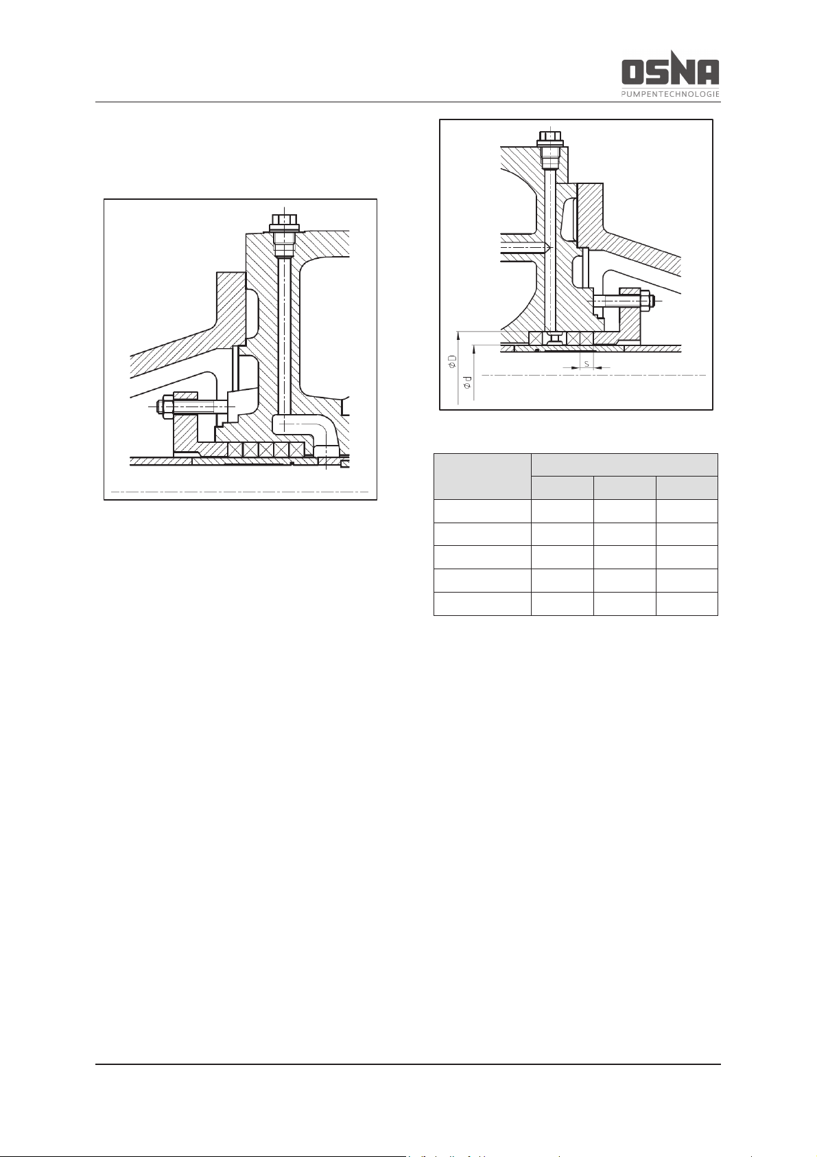
7 Maintenance and repair
48 NMH/NMV High Pressure Centrifugal Pump
longer possible to adjust the gland, insert an
additional packing ring or replace the packing
rings.
Figure 25: Pressure-side stuffing box (standard)
Replacing the packing rings:
1. Remove the old gland packing entirely
and clean the stuffing box.
2. Check the surface quality of the shaft
running surface.
3. Place new rings around the shaft.
When doing this:
- push in each new ring with the
gland
- rotate each new ring until the joints
are offset by 90°
4. Slightly tighten the nuts on the gland
by hand, alternating sides. Ensure that
the pump shaft rotates easily.
Figure 26: Suction-side stuffing box (standard)
Pump type
Dimensions [mm]
D d S
NMH/NMV 32
51
35
8
NMH/NMV 40
51
35
8
NMH/NMV 50
63
43
10
NMH/NMV 65
65
45
10
NMH/NMV 80
85
60
12
Table 16: Stuffing box dimensions
7.4 Sending the pump to the manufacturer
ü Pump depressurized
ü Pump completely drained
ü Electrical connections disconnected
and motor secured against reactivation
ü Pump cooled down
ü When using couplings with spacer:
spacer removed
Page 51
7 Maintenance and repair
NMH/NMV High Pressure Centrifugal Pump 49
ü Auxiliary operating system shut down,
depressurized and drained
ü Manometer removed together with
supply lines and holders
1. Only send pumps or individual components to the manufacturer together
with a verifiable and completely filled
out clearance certificate. Request a
clearance certificate from the manufacturer if required.
2. Using the following table, take the action required for returning the pump
according to the necessary repair.
Repair
Action for return
At customer
►Return defective component
to manufacturer.
At manufacturer
►Flush pump.
►Send complete pump
(not disassembled) to ma
n-
ufacturer.
At manufacturer,
with guarantee
claim
►Only when using hazardous
pumping medium: flush
pump.
►Send complete pump
(not disassembled) to ma
n-
ufacturer.
Table 17: Measures for return
7.5 Disassembling the pump
DANGER
Risk of death from electric shock!
► Only allow work on the electrical systems to
be carried out by a qualified electrician.
► Ensure that the supply of electricity is
switched off and secured against reactivation when performing all maintenance work.
DANGER
Risk of injury due to hot pump components!
► Use personal protective equipment when
performing work on the pump.
Page 52
7 Maintenance and repair
50 NMH/NMV High Pressure Centrifugal Pump
DANGER
Risk of injury due to running pump!
► Do not touch the running pump.
► Do not perform any work on the running
pump.
WARNING
Risk of poisoning or injury due to hazardous pumping media!
► Use personal protective equipment when
performing work on the pump.
ü Pump depressurized
ü Pump fully drained, flushed and de-
contaminated
ü Electrical connections disconnected
and motor secured against reactivation
ü Pump cooled down
ü Coupling guard removed
ü When using couplings with spacer:
spacer removed
ü Auxiliary operating system shut down,
depressurized and drained
ü Manometer removed together with
supply lines and holders
During disassembly:
· Precisely mark the installation location
and position of all components prior to
disassembly.
· This assembled components concen-
trically, and do not cant.
· Disassemble the pump (à Cross-
section diagram).
Page 53

7 Maintenance and repair
NMH/NMV High Pressure Centrifugal Pump 51
7.6 Ordering spare parts
Please have the following information to hand
when ordering spare parts (à type plate,
cross-section diagram):
· Customer number (if available)
· Short designation of the pump series
· Order number/pump number
· Year of production
· Parts number
· Designation
· Quantity
· Delivery method
· Delivery address
Page 54
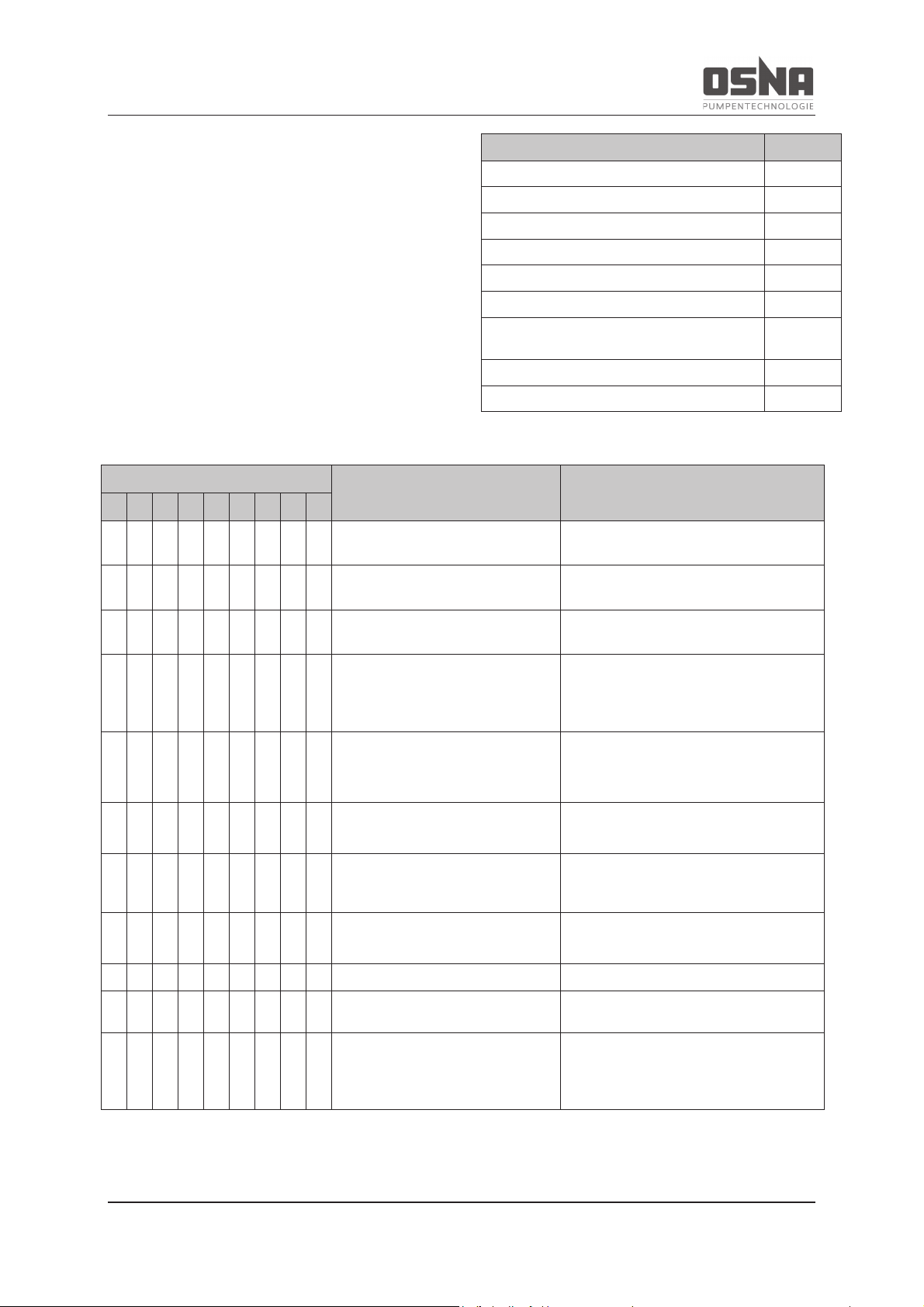
8 Faults and troubleshooting
52 NMH/NMV High Pressure Centrifugal Pump
8 Faults and troubleshooting
Please consult the manufacturer should you
experience any faults that are not described in
the following table, or cannot be traced back to
the described causes.
In the following table, each potential fault is
given a number. Use this number to find the
corresponding cause and remedy in the troubleshooting table.
Fault
Number
Pump does not deliver
1
Flow rate too low
2
Flow rate too high
3
Pumping pressure too low
4
Pumping pressure too high
5
Pump runs noisily
6
Temperature of the anti-friction bearings
too high
7
Pump leaks
8
Motor power consumption too high
9
Table 18: Fault/number allocation
Fault number
Cause
Remedy
1 2 3 4 5 6 7 8 9
X - - - - - - - -
Inlet/suction pipe and/or pressure
pipe closed by fitting
► Open fitting.
- X - X - - - - -
Inlet/suction pipe not completely
opened
► Open fitting.
X X - X - X - - -
Inlet/suction pipe, pump or suction
strainer blocked or encrusted
► Clean inlet/suction pipe, pump or
suction strainer.
- X - X - X - - -
Cross-section of the inlet/suction
pipe too tight
► Enlarge cross
-section.
► Clean suction pipe of encrustations.
► Fully open fitting.
X - - - - - - - -
Transport sealing cap not r
e-
moved
► Remove transport sealing cap.
► Disassemble pump and check for
dry running damage.
- X - X - X - - -
Suction head too high: NPSH
pump
is greater than NPSH
system
► Increase inlet pressure.
► Consult manufacturer.
X - - - - X - - -
Inlet/suction pipe and pump not
correctly drained or not completely filled.
► Completely fill and drain pump
and/or pipeline.
X - - - - X - - -
Inlet/suction pipe contains air
pockets
► Install fitting for venting.
► Correct pipeline routing.
X X - X - X - - -
Air sucked in
► Seal source of fault.
X X - X - X - - -
Gas component too high: pump
cavitated
► Consult manufacturer.
- X - X - X - - -
Temperature of pumping medium
too high: pump cavitated
► Increase
inlet pressure.
► Reduce temperature.
► Consult manufacturer.
Page 55
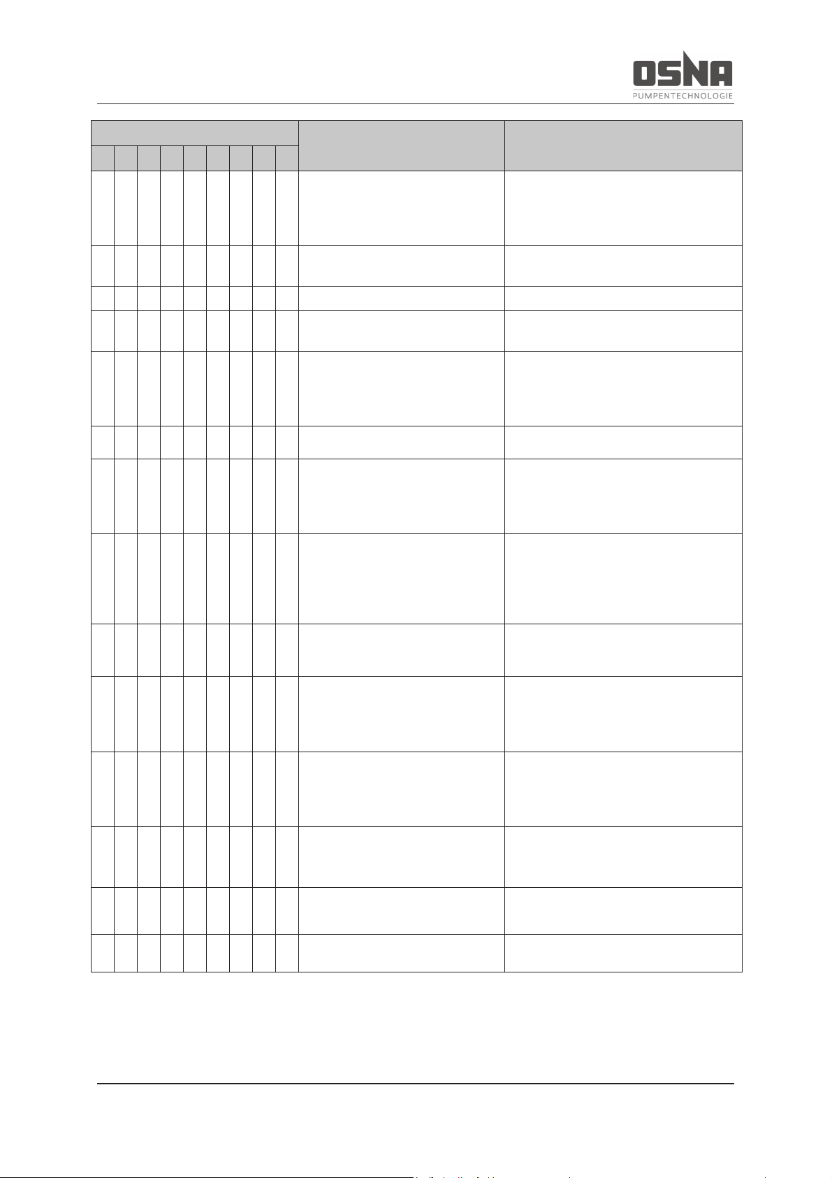
8 Faults and troubleshooting
NMH/NMV High Pressure Centrifugal Pump 53
Fault number
Cause
Remedy
1 2 3 4 5 6 7 8 9
- X - X - - - - -
Geodetic delivery head and/or
pipeline resistance too high
► Remove deposits in pump and/or
pressure pipe.
► Install larger impeller and consult
manufacturer.
- X - - X X - - -
Pressure-side fitting not opened
far enough
► Open pressure
-side fitting.
X X - - X X - - -
Pressure line blocked
► Clean pressure line.
X X - X - X - - -
Incorrect direction of rotation on
pump
►
Swap any two phases on motor.
X X - X - - - - -
Speed too low
► Compare required motor speed with
pump type plate. Replace motor if necessary.
► Increase speed if possible.
- X - X - X X - -
Pump components worn
► Replace worn pump components.
- - X X - X - - X
Pressure-side fitting opened too
far
► Throttle with pressure
-side fitting.
► Machine down impeller. Consult
manufacturer and adjust impeller diameter.
- - X - - X - - X
Geodetic delivery head, pipeline
resistance and/or other resistances lower
than designed
► Throttle flow rate with pressure-side
fitting. Observe minimum flow rate here.
► Machine down impeller. Consult
manufacturer and adjust impeller diameter.
- - X - X - - - -
Viscosity lower than indicated
► Machine down impeller. Consult
manufacturer and adjust impeller diameter.
- - X - X X X - X
Speed too high
► Compare required motor speed with
pump type plate. Replace motor if necessary.
► Reduce speed if possible.
- - X - X X - - X
Number of stages too high
► Throttle flow rate with
pressure-
side
fitting. Observe minimum flow rate here.
► Install pump with lower number of
stages.
X X - X - X - - -
Impeller imbalanced or blocked
► Disassemble pump and check for
dry running damage.
► Clean impeller.
- X - X - X - - -
Hydraulic pump components dirty,
sticky or encrusted
► Disassemble pump.
► Clean components.
- - - - - - X - X
Defective anti-friction bearing in
motor
► Replace anti
-friction bearing.
Page 56
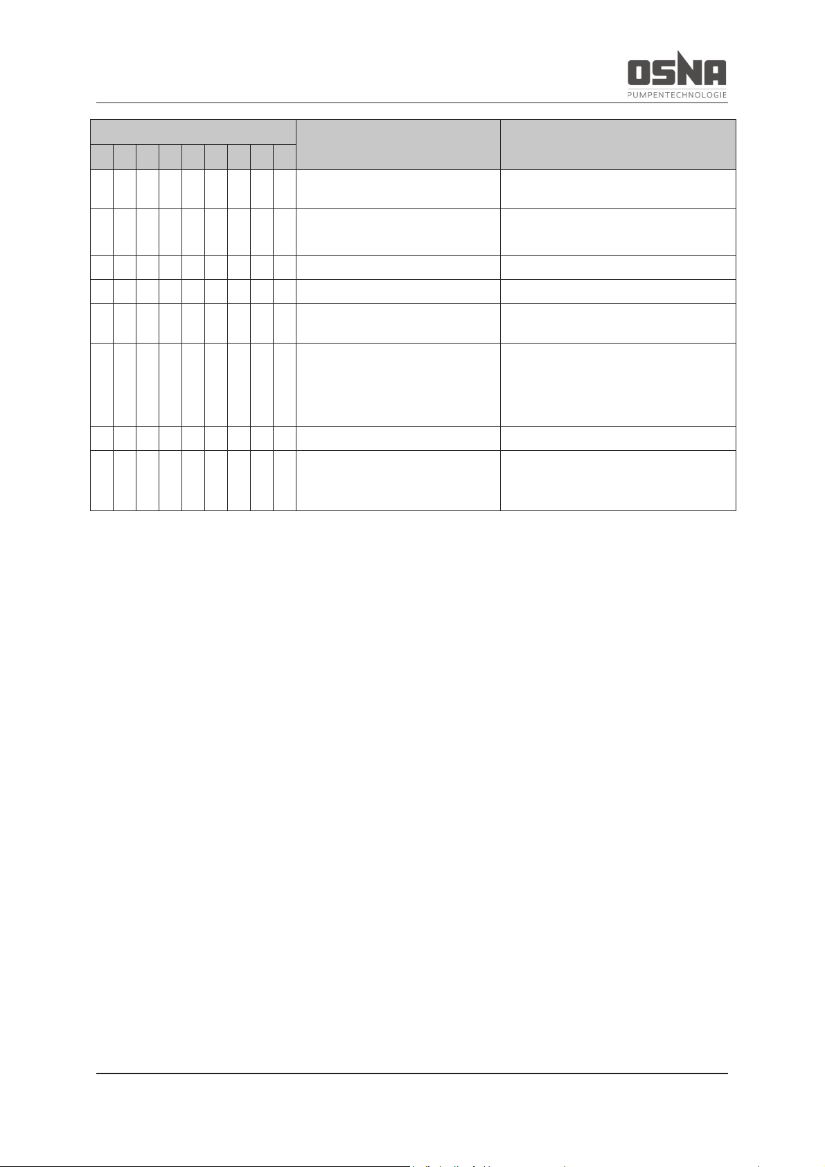
8 Faults and troubleshooting
54 NMH/NMV High Pressure Centrifugal Pump
Fault number
Cause
Remedy
1 2 3 4 5 6 7 8 9
- - - - - - X - -
Lubricant: too much, too little or
not suitable
► Reduce, increase or replace lubricant.
- - - - - - - X -
Tie bolts not tightened correctly
► Tighten tie bolts.
- - - - - - - X -
Mechanical seal worn
► Replace mechanical seal.
- - - - - - - X -
Defective casing seal
► Replace casing seal.
- - - - - - - X -
Shaft sleeve penetrated
► Replace shaft sleeve and round
seal.
- - - - - X X X X
Pump under tension
► Check pipeline connections and
pump fastening.
► Check coupling alignment.
► Check support foot fastening.
- - - - - X X - -
Coupling incorrectly aligned
► Align coupling.
- X - X - X - - X
Motor runs on 2 phases
► Check fuse and replace if necessary.
► Check wire connections and insula-
tion.
Table 19: Troubleshooting table
Page 57

9 Appendix
NMH/NMV High Pressure Centrifugal Pump 55
9 Appendix
9.1 Additional ATEX instructions
Additional requirements for safe operation
in areas at risk of explosion
9.1.1 Safety
Correct and proper use:
The pump is classified as non-electric equipment, and therefore fulfills the requirements for
devices of equipment group II, categories 2
and 3.
Do not operate the pump:
- when the fittings are closed
- when the operating range is exceeded
(à data sheet)
- when maintenance intervals are exceeded
Duties of the system owner:
· Assess and document the risk of ex-
plosion in the various operating areas
of the system according to Annex I of
the Directive 2014/34/EU.
· Ensure compliance with Directive
99/92/EC on measures for ensuring
the health and safety of workers in atmospheres at risk of explosion.
· Only operate the pump in line with the
explosion protection marking.
· Observe the enclosed data sheet.
· Ensure the following at all times:
- Pump earthed (earthing screw lo-
cated on the bearing housing of
the pump) à 5.7.2 Earthing the
pump, pg 35
- No contact between the coupling
and the coupling guard
- Suction and pressure pipe, inside
of the pump, seal area and auxiliary systems completely filled with
pumping medium at all times
- Authorized surface temperature
on the pump not exceeded
- Fittings installed correctly on the
suction and pressure side
- Pump serviced regularly and
monitored
- No risk of dry pump running, e.g.
via level monitoring or flow rate
measurement
· Ensure that motors, couplings and
monitoring devices provided by the
customer meet the specified category
and temperature class in the respective zone.
· Inform personnel of the particular risk
of explosion when removing dust deposits.
Materials and media:
Ensure the following:
· All attachment parts are electrically
conductive
· Electrostatic charging is avoided: Only
use pumping media with a conductivity
> 10-8 S/m.
Page 58
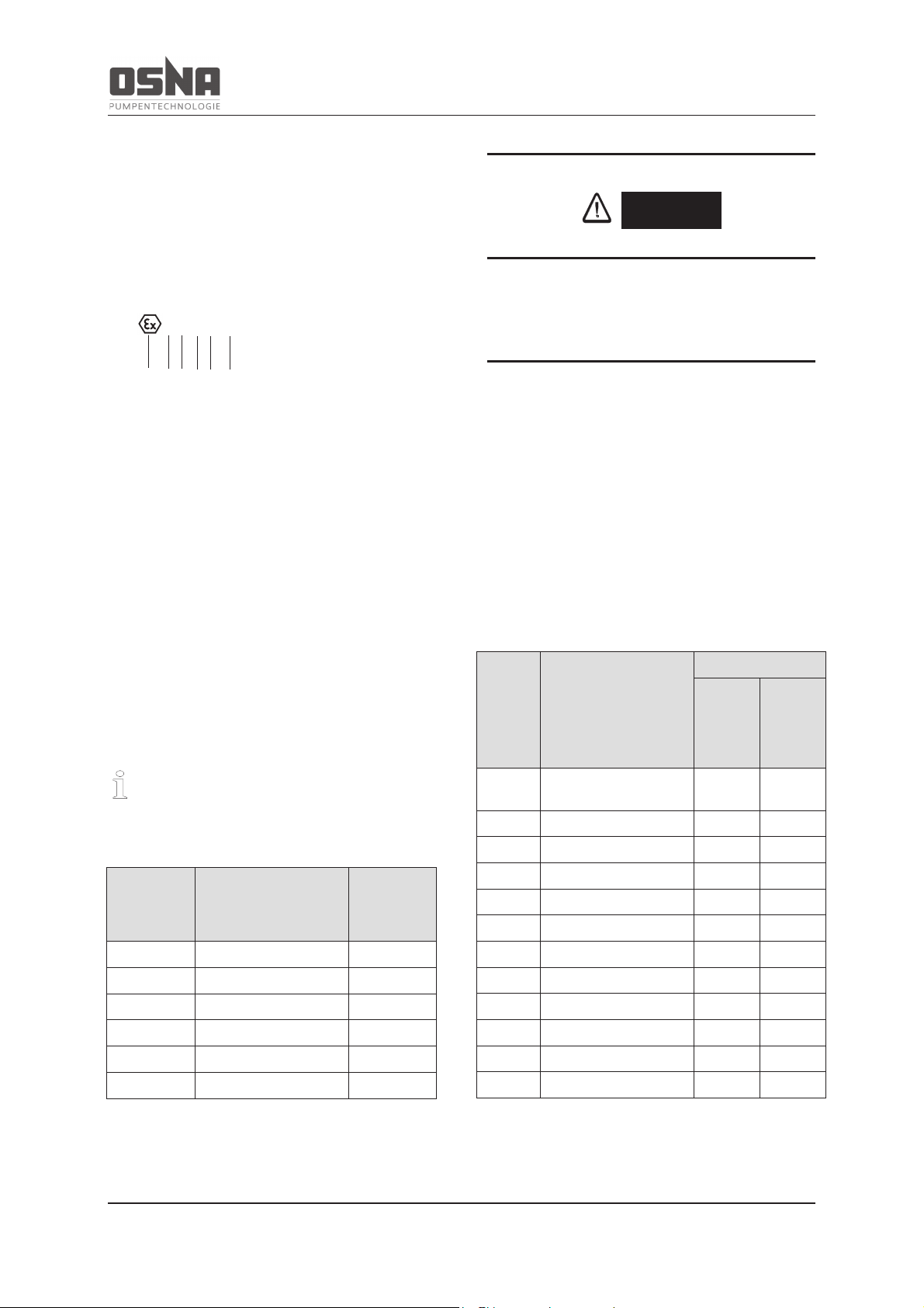
Appendix
56 NMH/NMV High Pressure Centrifugal Pump
9.1.2 Explosion protection marking
ATEX marking
The pumps in the NMH/NMV series meet the
following ATEX Ex protection class:
II G 2 c T3
1 2 3 4 5 6
Key:
1 ATEX symbol
2 Equipment group 2
3 Gases
4 Category 2
5 Constructional safety
6 Temperature class 3
Temperature classes:
Flammable gases and vapors are divided
into temperature classes according to their
inflammability in contact with hot surfaces.
Temperature class
Mixture ignition
temperature [°C]
Max. surface temperature
[°C]
T1
t > 450
450
T2
450 ≥ t > 300
300
T3
300 ≥ t > 200
200
T4
200 ≥ t > 135
135
T5
135 ≥ t > 100
100
T6
100 ≥ t > 85
85
Table 20: Temperature classes
DANGER
Only use the pump up to the temperature
class indicated on the type plate.
The surface temperature of the pump must
always be lower than the lowest ignition temperature of the temperature class.
Ignition protection class:
The ignition protection class describes the type
of measures taken to prevent a surrounding
explosive atmosphere from igniting.
Ign
i-
tion
pr
o-
tection
class
Meaning
For area
Non-
electri-
cal
equip
ment
Ele
c-
trical
equip
ment
b
Control of ignition
sources
X
-
c
Constructional safety
X
-
d
Flameproof enclosure
X
X
e
Increased safety
-
X
fr
Flow restriction
X
-
g
Inherent safety
X
-
k
Liquid immersion
X
-
o
Oil immersion
-
X
p
Pressurization
X
X
q
Powder filling
-
X
m
Encapsulation
-
X
i
Intrinsic safety
-
X
Table 21: Ignition protection classes
Page 59
9 Appendix
NMH/NMV High Pressure Centrifugal Pump 57
Ex atmosphere
The Ex atmosphere describes the type of explosive atmosphere in a zone.
Ex atmosphere
Meaning
G Flammable gases and vapors
D Flammable dusts
Table 22: Ex atmosphere
Equipment groups/areas of use/zone/category
Pumps are divided into equipment groups and
categories according to the area in which they
are used. The zone is based on the likelihood
of an explosive atmosphere, and differentiates
between gases and dusts. The category describes the constructional safety of the pump,
and depends on the zone.
Equipment
group/area of
use
Zone
Category
Likelihood of dangerous explo-
sive atmospheres
Constructional safety
I / mining
Comparable to 0
(G) and 1 (G)
M1
-
Very high
I / mining
Comparable to 2
(G)
M2
-
High
II / others
0 (G) 20 (D)
1
Persistent, for long periods or
frequently
Very high
II / others
1 (G) 21 (D)
2
Occasional (arising fault must
not become source of ignition)
High
II / others
2 (G) 22 (D)
3
Unlikely, if so then rarely and
briefly (surface temperature
must not become an ignition
source in normal operation)
Normal
Table 23: Equipment groups/areas of use/zone/category
9.1.3 Installation and connection
The required measures for installation and
connection depend on the category (à
9.1.2 Explosion protection marking, pg 56).
Performing basic measures
· Only use touch guard elements (e.g.
coupling guard) made from electrically
conductive materials.
· Secure the grub screw for connecting
the coupling halves (e.g. using Loctite
medium strength)
· Remove any metal shavings and dirt
residues from all touch guard elements.
· Install a soft-closing non-return valve
between the discharge nozzle and the
shut-off valve to prevent the backflow
of pumping medium after the pump is
switched off.
Page 60
9 Appendix
58 NMH/NMV High Pressure Centrifugal Pump
· The motor must meet the require-
ments of the area at risk of explosion
(group, category).
· If using a frequency inverter, please
consult the manufacturers of the pump
and the frequency inverter beforehand.
Performing measures for category 2
Ensure that there are monitoring devices to
prevent self-warming caused by dry running.
Type and configura
tion of shaft seal
(
à data sheet)
Measure
Single mechanical seal
If the pumping medium contains gas
-laden substances:
► Ensure that the following components for temperature measurement on the stationary seal ring of the mechanical seal meet
the
specifications of Directive 2014/34/EU:
-
Temperature sensor on stationary seal ring of the mechan-
ical seal
- Temperature monitoring instrument
► Retrofit an appropriate temperature measuring instrument if
required
Double mechanical seal in back
-to-
back
configuration
► Retrofit a pressure gauge for the sealing medium
Double mechanical seal in tandem configuration
► Retrofit a fill level gauge for the supply tank if necessary.
► Retrofit a pressure gauge for the sealing medium if the tem-
perature difference between the sealing medium and the temperature class < 50 Kelvin.
Single mechanical seal with quench and
secondary seal with lip
Table 24: Possible devices for monitoring self-warming due to dry running
Monitoring the system for parameter behavior
Parameter 1)
Measure
Constant
► Monitor motor power:
- Reaction time < 5 s
- Precision < 15 %
-
Record of the effective
power of all three phases
-
Monitoring of overload
and underload
► Alternatively: Monitor flow
rate and/or tank level (à data
sheet)
At least one not
constant
► Monitor flow rate and/or tank
level
- Reaction time < 5 s
-
Monitor minimum and
maximum value (à
data
sheet)
Table 25: Measures against unauthorized self-warming
1) Flow rate, delivery head, density, viscosity, speed, output
Ensuring ignition source monitoring
Ensure that ignition sources are monitored as
per the minimum requirements of the ignition
protection level (IPL) according to EN 13463-6
(or DIN EN ISO 13849-1 for monitoring devices that are not IPL certified):
IPL 1 for category 2
IPL 2 for category M2 / mining
Page 61
9 Appendix
NMH/NMV High Pressure Centrifugal Pump 59
9.1.4 Operation
Observing the maximum authorized operating temperature
Observe the maximum authorized operating
temperature (à data sheet).
Observing the maximum authorized temperature of the pumping medium
Temperature class
Authorized pumping medium temperature [°C] 1)
T4
80
T3
140
T2
140
T1
140
Table 26: Max. pumping medium temperature
1) Applies to the specific heat capacity of
water (c
Water
= 4.2 KJ/kgK) and at speeds
< 3000 min-1
Safe operation
Ensure the following operating conditions:
· No dry running
· No operation while overloaded
· No operation when the suction-side fit-
tings are closed
· No operation (even briefly when start-
ing) when the pressure-side fittings are
closed
9.1.5 Maintenance and repair
Maintenance intervals shorten under difficult operating conditions.
Performing measures
· Replace the anti-friction bearing in the
motor in line with the manufacturer
specifications.
· Replace the anti-friction bearing and
the plain bearing in the pump after
9000 operating hours.
· Check the following at appropriate in-
tervals (at least monthly):
- Motor and coupling in line with the
manufacturer's operating manual
- Surface temperature of the motor
and pump
- Any changes in running noise or
vibrations
- Deformation of the touch guard elements and distance to the hazardous parts
- Function of the monitoring devices
Page 62
9 Appendix
60 NMH/NMV High Pressure Centrifugal Pump
9.2 Spare parts list for constant operation over two years as per DIN 24296
Part no.
Part designation
Number of identical pumps
(including reserve pumps)
2 3 4 5 6 and 7
8 and 9
> 9
Set/quantity of spare parts
211
Pump shaft with small parts
1 1 2 2 2
3
30%
230
Impeller (set)
1 1 1 2 2
3
30%
321 Radial grooved ball bearing
(set)
1 1 2
2 3 4
50%
370
Foil bearing
1 1 2 2 3
4
50%
412
Round seal (set)
4 8 8 8 9
12
150%
433
Mechanical seal (set)
2 3 4 5 6
7
90%
461
Gland packing (set)
4 6 8 8 9
12
150%
504
Correction ring
1 1 2 2 3
4
50%
524
Shaft wearing sleeve
2 2 2 3 3
4
50%
525
Interstage sleeve
2 2 2 3 3
4
50%
Table 27: Spare parts for constant operation over two years
Page 63
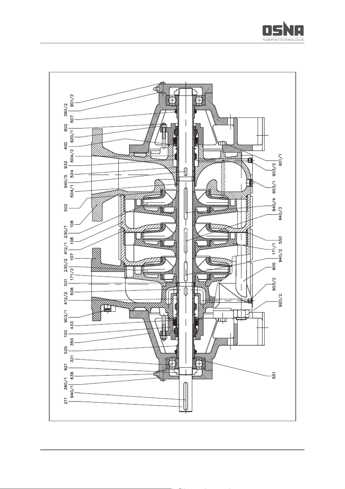
9 Appendix
NMH/NMV High Pressure Centrifugal Pump 61
9.3 Cross-sections
Figure 27: Cross-section of NMH with mechanical seal
Page 64
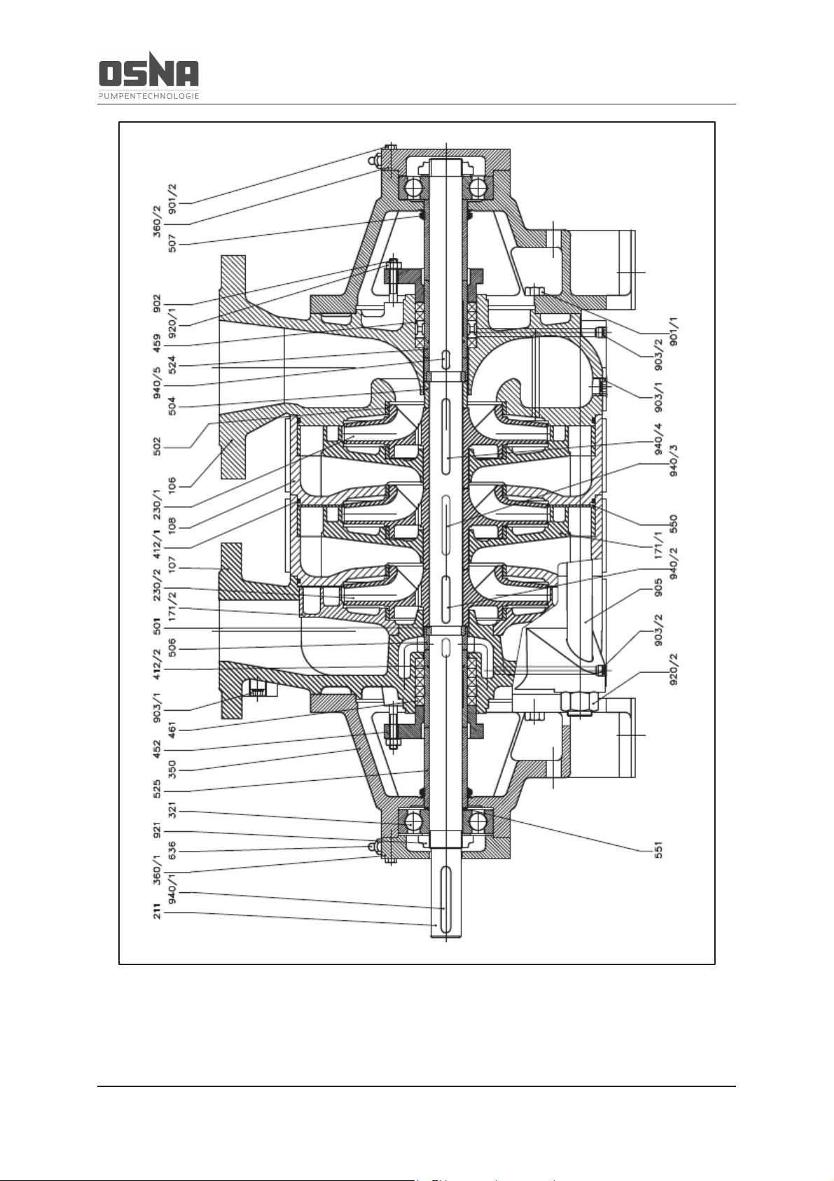
9 Appendix
62 NMH/NMV High Pressure Centrifugal Pump
Figure 28: Cross-section of NMH with gland packing
Page 65
9 Appendix
NMH/NMV High Pressure Centrifugal Pump 63
Part no.
Designation
Part no.
Designation
100
Casing
501
Multiple ring
106
Suction casing
502
Casing wear ring
107
Delivery casing
504
Correction ring
108
Stage casing
504/1
Spacer ring
171/1
Diffuser
504/2
Spacer ring
171/2
Diffuser
506
Retaining ring
507
Thrower
524
Shaft wearing sleeve
211
Pump shaft
525
Spacer sleeve
230/1
Impeller
550
Disc
230/2
Impeller
551
Support disc
321
Radial grooved ball bearing
636
Grease nipple
350
Bearing housing
360/1
Bearing cover
360/2
Bearing cover
901/1
Hexagon head bolt
901/2
Hexagon head bolt
902
Stud
400
Gasket
903/1
Screwed plug
412/1
O-ring
903/2
Screwed plug
412/2
O-ring
905
Tie bolt
433
Mechanical seal
920/1
Hexagon nut
920/2
Hexagon nut
921
Shaft nut
452
Gland
932
Circlip
459
Lantern neck bush
940/1
Key
461
Gland packing
940/2
Key
940/3
Key
940/4
Key
940/5
Key
Table 28: NMH parts list
Page 66
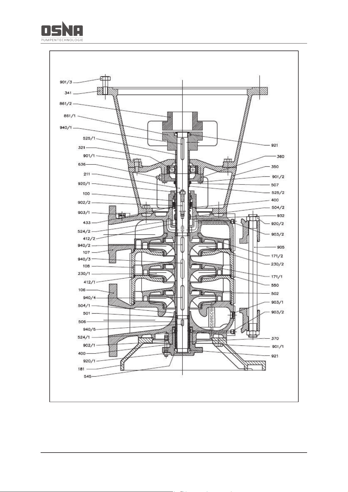
9 Appendix
64 NMH/NMV High Pressure Centrifugal Pump
Figure 29: Cross-section of NMV with mechanical seal
Page 67
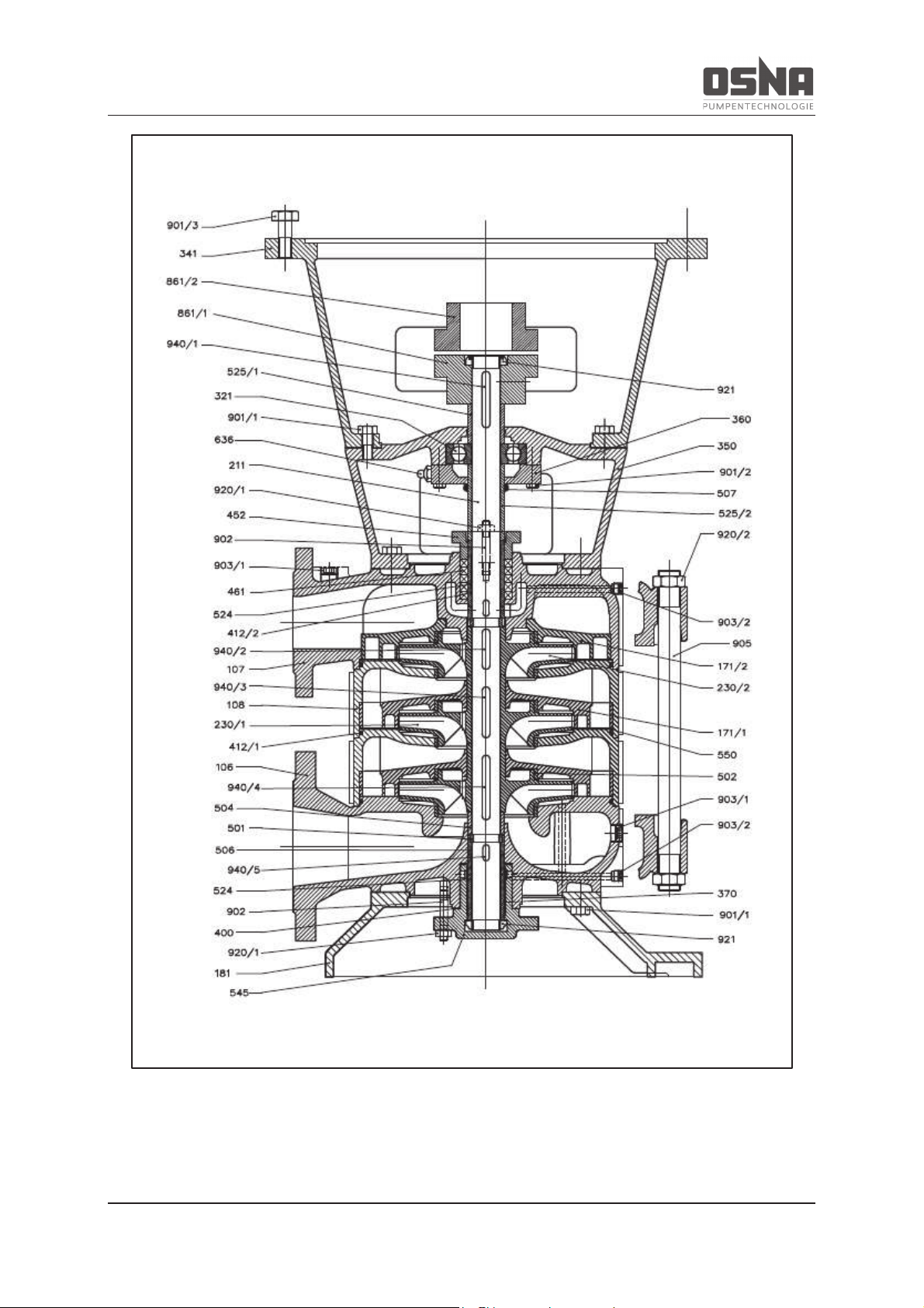
9 Appendix
NMH/NMV High Pressure Centrifugal Pump 65
Figure 30: Cross-section of NMV with gland packing
Page 68
9 Appendix
66 NMH/NMV High Pressure Centrifugal Pump
Part no.
Designation
Part no.
Designation
100
Casing
501
Multiple ring
106
Suction casing
502
Casing wear ring
107
Delivery casing
504
Correction ring
108
Stage casing
504/1
Spacer ring
171/1
Diffuser
504/2
Spacer ring
171/2
Diffuser
506
Retaining ring
181
Pump stool
507
Thrower
524
Shaft wearing sleeve
524/1
Shaft wearing sleeve
211
Pump shaft
524/2
Shaft wearing sleeve
230/1
Impeller
525/1
Spacer sleeve
230/2
Impeller
525/2
Spacer sleeve
545
Bearing bush
550
Disc
321
Radial grooved ball bearing
341
Motor stool
350
Bearing housing
636
Grease nipple
360
Bearing cover
370
Bearing shell
861/1
Pump-side coupling half
861/2
Motor-side coupling half
400
Gasket
412/1
O-ring
412/2
O-ring
901/1
Hexagon head bolt
433
Mechanical seal
901/2
Hexagon head bolt
901/3
Hexagon head bolt
902
Stud
452
Gland
903/1
Screwed plug
461
Gland packing
903/2
Screwed plug
905
Tie bolt
920/1
Hexagon nut
920/2
Hexagon nut
921
Shaft nut
932
Circlip
940/1
Key
940/2
Key
940/3
Key
940/4
Key
940/5
Key
Table 29: NMV parts list
Page 69
9 Appendix
NMH/NMV High Pressure Centrifugal Pump 67
9.4 Declaration of Conformity as per EC Directive 2006/42/EC, Annex IIA
We hereby declare under our sole responsibility as manufacturer that the following machine series
conform to the relevant specifications of the EC Machinery Directive 2014/34/EC both in their type
and in the configurations distributed by us.
Designation: NMH/NMV 32/40/50/65/80
Pump number: 170000 - 200000
The machine also corresponds with the following directives published in the Official Journal of the
European Union:
· Niederspannungsrichtlinie (2014/35/EC)
This declaration shall cease to be valid in the event of any modifications to the machine and/or its
protective mechanisms not agreed with us and approved in writing.
Applied harmonized standards and their references in the Official Journal of the European Union:
· DIN EN 809 : 2012
· DIN EN ISO 12100 : 2011
· DIN EN ISO 13732 : 2008
· DIN EN ISO 13857 : 2008
· DIN EN 60034 : 2007
· DIN EN 60204-1 : 2009
Authorized representative for the composition of technical documentation for OSNA-Pumpen GmbH:
Mr. Rik Arensmann
Brückenstrasse 3
49090 Osnabrück, Germany
Osnabrück, 31.10.2016 _______________________________
Rik Arensmann
Technical Director/QM Officer
Page 70
9 Appendix
68 NMH/NMV High Pressure Centrifugal Pump
9.5 Declaration of Conformity as per EC Directive 2014/34/EC, Annex VI
We hereby declare under our sole responsibility as manufacturer that the following machine series of
the type, as well as the configurations distributed by us, conform to the relevant specifications of the
EC Directive 2014/34/EC.
Designation: NMH/NMV 32/40/50/65/80
Pump number: 170000 - 200000
The machine corresponds to the following protection class:
II 2 G c T3
This declaration shall cease to be valid in the event of any modifications to the machine and/or its
protective mechanisms not agreed with us and approved in writing.
Applied harmonized standards and their references in the Official Journal of the European Union:
· DIN EN ISO 13463-1 : 2009
· DIN EN ISO 13463-5 : 2011
· DIN EN ISO 15198 : 2007
Authorized representative for the composition of technical documentation for OSNA-Pumpen GmbH:
Mr. Rik Arensmann
Brückenstrasse 3
49090 Osnabrück, Germany
Osnabrück, 24.02.2017 _______________________________
Rik Arensmann
Technical Director/QM Officer
Page 71

9 Appendix
NMH/NMV High Pressure Centrifugal Pump 69
9.6 Clearance Certificate
Please copy and send with the pump.
Clearance Certificate
Legal provisions oblige all businesses to protect their employees, other persons and the environment
from damaging effects when handling hazardous substances. Products and their components may
therefore only be repaired or inspected when the following declaration has been fully and correctly
filled out and singed by an authorized and qualified specialist. Please provide the necessary information should safety measures on the part of the system owner still be required despite complete
draining and cleaning. This clearance certificate is part of the repair or inspection order.
We hereby assure that the enclosed device
Type: ______________________________________________________________
Serial no.: ______________________________________________________________
is free of substances that are hazardous to health. No special safety measures are required for further
handling. The device was fully drained and thoroughly cleaned inside and outside before dispatch.
Company/institute: ______________________________________________________________
Address: ______________________________________________________________
Town/city, ZIP code: ______________________________________________________________
Phone: ______________________________________________________________
Name: ______________________________________________________________
Position: ______________________________________________________________
Date: ______________________________________________________________
Signature, company stamp: ________________________________________________________
Page 72
Notes
_________________________________________________________________________________
_________________________________________________________________________________
_________________________________________________________________________________
_________________________________________________________________________________
_________________________________________________________________________________
_________________________________________________________________________________
_________________________________________________________________________________
_________________________________________________________________________________
_________________________________________________________________________________
_________________________________________________________________________________
_________________________________________________________________________________
_________________________________________________________________________________
_________________________________________________________________________________
_________________________________________________________________________________
_________________________________________________________________________________
PUMPS
SYSTEMS
WATER TREATMENT
ENGINEERING
SERVICES
OSNA-Pumpen GmbH Your no. 1 choice for the solution you need:
Brückenstrasse 3
49090 Osnabrück, Germany - Consulting - Training
Phone: +49 541 1211 – 0 - Planning - Maintenance
Fax: +49 541 1211 – 220 - Project management - Repair
Internet: http://www.osna.de - Assembly
E-mail: [email protected]
OSNA customer service Tel.: +49 541 1211 – 254
Emergency service Tel.: +49 171 4151 – 674
 Loading...