

Page 1
Ver.17-01
Original Operating Manual
CVP High-Pressure Centrifugal Pump
OSNA-Pumpen GmbH
Brückenstrasse 3
49090 Osnabrück, Germany
Phone: +49 541 1211 - 0
Fax: +49 541 1211 - 220
Internet: http://www.osna.de
E-mail: [email protected]
Page 2

Page 3

CVP High-Pressure Centrifugal Pump 1
Contents
1 GENERAL ...................................................................................................................................4
1.1 About this operating manual ..................................................................................................4
1.2 Target groups .......................................................................................................................4
1.3 Other valid documents ..........................................................................................................4
1.4 Warning notices and symbols ................................................................................................5
1.5 Copyright/changes ................................................................................................................5
2 SAFETY ......................................................................................................................................6
2.1 Correct and proper use .........................................................................................................6
2.2 General safety instructions ....................................................................................................7
2.2.1 Product safety ................................................................................................................7
2.2.2 Duties of the system owner ............................................................................................7
2.2.3 Duties of personnel ........................................................................................................8
2.3 Dangers of non-observance of the safety instructions ............................................................9
2.4 Unauthorized conversion and production of spare parts.........................................................9
2.5 Unauthorized modes of operation ..........................................................................................9
2.6 Special hazards ....................................................................................................................9
2.6.1 Explosion area ...............................................................................................................9
2.6.2 Hazardous pumping media .............................................................................................9
2.6.3 Noise emissions .............................................................................................................9
3 LAYOUT AND FUNCTION ........................................................................................................ 10
3.1 Labeling .............................................................................................................................. 10
3.2 Scope of delivery for a type-CVP high-pressure centrifugal pump ........................................ 10
3.3 General information............................................................................................................. 11
3.4 Technical data .................................................................................................................... 11
4 TRANSPORT AND INTERMEDIATE STORAGE ....................................................................... 13
4.1 Transport ............................................................................................................................ 13
4.1.1 Unpacking and checking the delivery condition ............................................................. 13
4.1.2 Lifting ........................................................................................................................... 13
4.2 Intermediate storage ........................................................................................................... 14
4.3 Storage ............................................................................................................................... 14
4.4 Disposal .............................................................................................................................. 15
5 ASSEMBLY AND INSTALLATION ............................................................................................ 16
5.1.1 Preparing the installation location ................................................................................. 16
5.1.2 Preparing the base surface and foundations ................................................................. 16
5.2 Installation .......................................................................................................................... 16
5.2.1 Installing the pump ....................................................................................................... 16
5.2.2 Assembling the motor................................................................................................... 17
Page 4

2 CVP High-Pressure Centrifugal Pump
5.2.3 Electrical connection .................................................................................................... 18
5.2.4 Adjusting the pump rotor .............................................................................................. 19
5.3 Pipelines ............................................................................................................................. 20
6 COMMISSIONING/ DECOMMISSIONING ................................................................................. 22
6.1 Commissioning ................................................................................................................... 22
6.1.1 Determining the pump configuration ............................................................................. 22
6.1.2 Filling the pump ............................................................................................................ 22
6.1.3 Checking direction of rotation ....................................................................................... 22
6.1.4 Starting the pump ......................................................................................................... 23
6.2 Decommissioning ................................................................................................................ 24
6.2.1 Draining the pump and protecting against frost ............................................................. 25
6.3 Recommissioning ................................................................................................................ 25
6.4 Mechanical seal .................................................................................................................. 25
7 MAINTENANCE AND REPAIR .................................................................................................. 27
7.1 General information............................................................................................................. 27
7.2 Sending the pump to the manufacturer ................................................................................ 28
8 FAULTS AND TROUBLESHOOTING........................................................................................ 29
9 APPENDIX ................................................................................................................................ 32
9.1 Service, spare parts, accessories ........................................................................................ 32
9.2 Individual parts of the CVP centrifugal pump ....................................................................... 33
9.3 Declaration of Conformity as per EC Directive 2006/42/EC, Annex IIA ................................. 35
9.4 Clearance Certificate ........................................................................................................... 36
Page 5

CVP High-Pressure Centrifugal Pump 3
List of Tables
Table 1: Target groups and their tasks ................................................................................................4
Table 2: Other valid documents and their purposes ............................................................................4
Table 3: Warning notices and consequences of non-observance ........................................................5
Table 4: Symbols and their meanings ..................................................................................................5
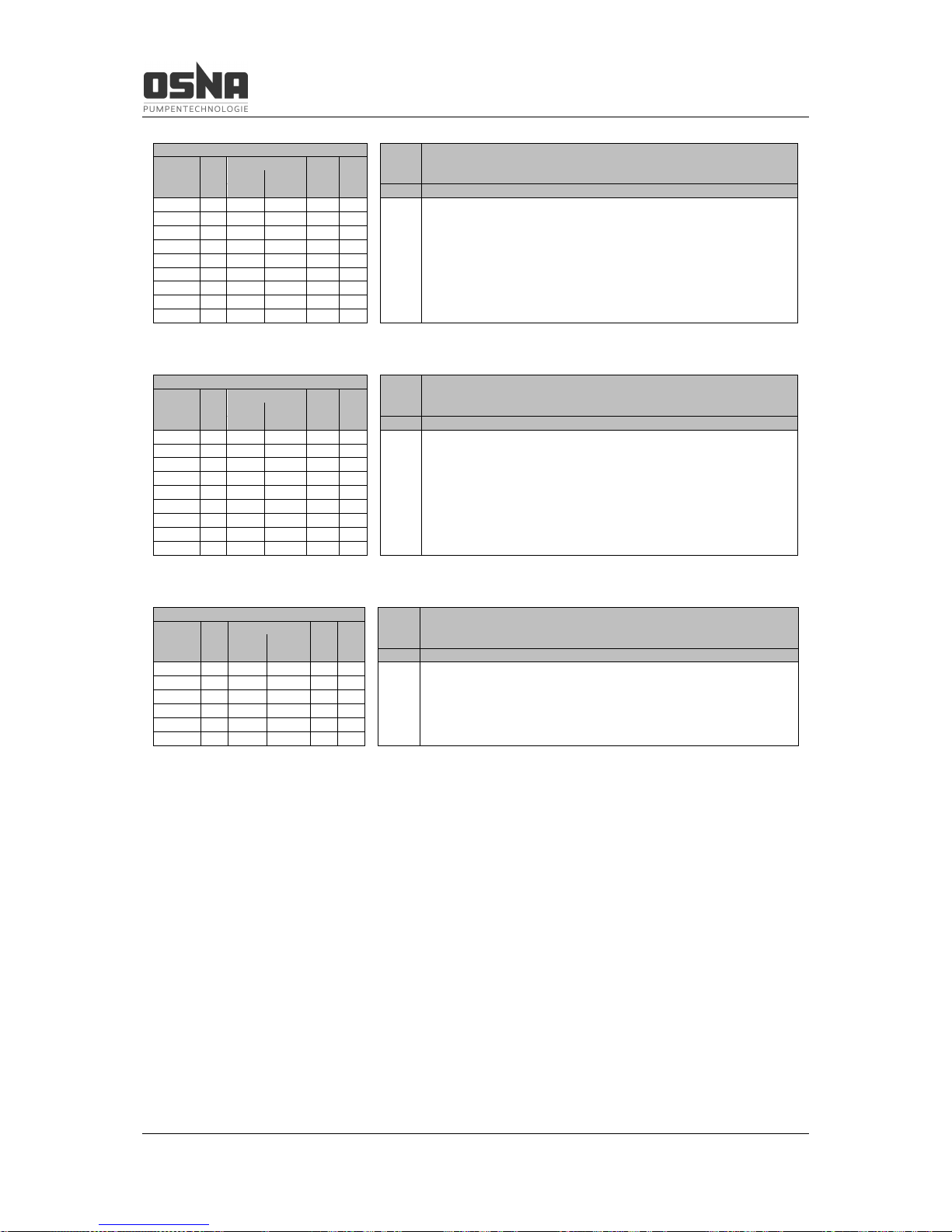
Table 5: Values table CVP 423 ......................................................................................................... 12
Table 6: Values table CVP 426 ......................................................................................................... 12
Table 7: Values table CVP 428 ......................................................................................................... 12
Table 8: Measures in the event of operational interruption ................................................................ 24
Table 9: Measures depending on the behavior .................................................................................. 24
Table 10: Measures following longer shut down times ....................................................................... 25
Table 11: Measures for return ........................................................................................................... 28
Table 12: Fault/number allocation ..................................................................................................... 29
Table 13: Troubleshooting table ........................................................................................................ 31
Table 14: Parts list of the CVP centrifugal pump ................................................................................ 34
List of Images
Figure 1: CVP model code ................................................................................................................ 10
Figure 2: Scope of delivery for type CVP ........................................................................................... 10
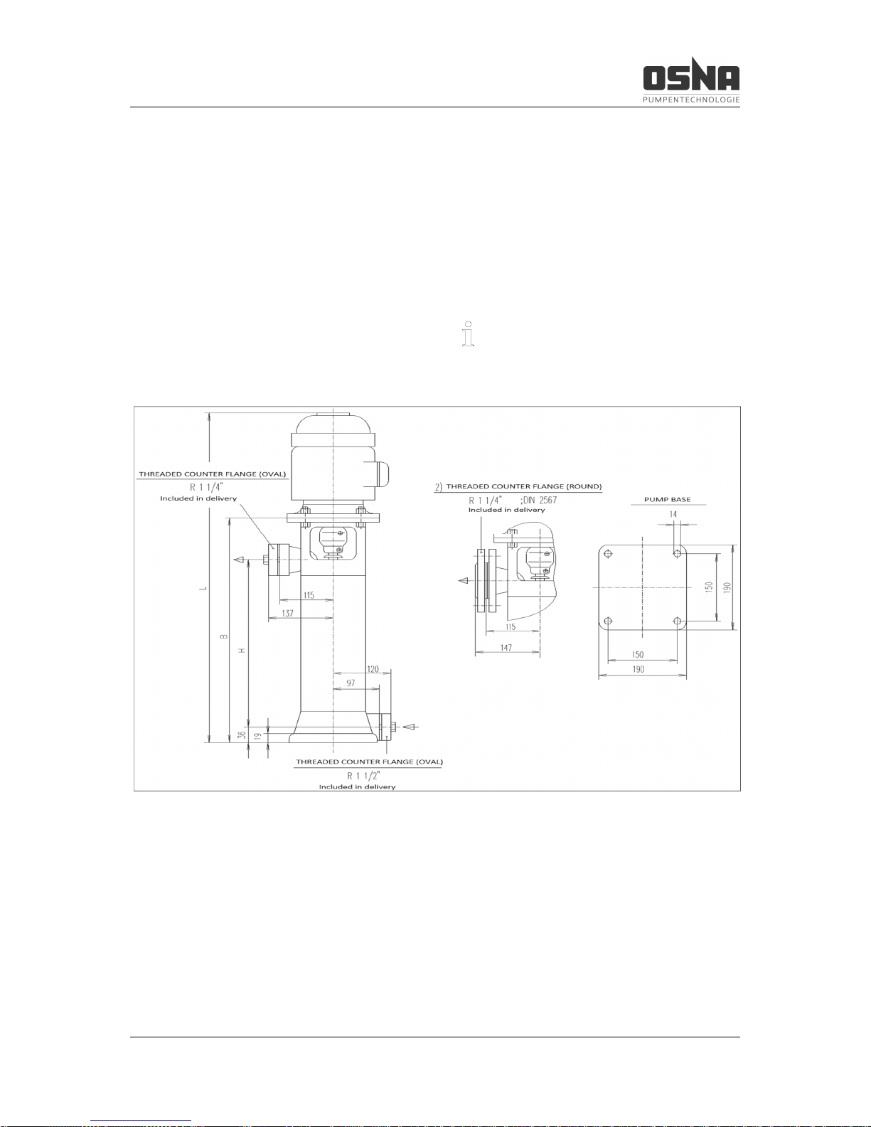
Figure 3: Dimensions on the CVP centrifugal pump ........................................................................... 11
Figure 4: Lifting a CVP centrifugal pump ........................................................................................... 13
Figure 5: Foundation plan for CVP 423 to 428 ................................................................................... 17
Figure 6: Overhead view of coupling ................................................................................................. 18
Figure 7: Adjusting the pump rotor .................................................................................................... 19
Figure 8: Functional and operating elements ..................................................................................... 20
Figure 9: Explosion diagram of the CVP centrifugal pump ................................................................. 33
Page 6
1 General
4 CVP High-Pressure Centrifugal Pump
1 General
1.1 About this operating manual
This operating manual contains important instructions that must be observed during installation, operation and maintenance. For this
reason, ensure that it is read by specialist personnel and the responsible operator/owner
prior to assembly and commissioning. The
manual must be available at all times at the location where the system is used.
Please observe the safety instructions described in this operating manual, along with the
relevant national accident prevention regulations and any internal work, operational and
safety specifications of the operator. We assume no liability for damages and operational
interruptions resulting from non-observance of
this operating manual.
WARNING
Pay particular attention to section 2 "Safety instructions" during commissioning and all
maintenance work.
Section 2 also provides an explanation of the
symbols used in this manual. Knowledge of
this operating manual is essential to preventing
errors and ensuring safe and uninterrupted
operation.
The operating specification does not take local
safety regulations into account. The owner
bears full responsibility for compliance with
these, including on the part of the assembly
personnel used.
This operating manual:
· is part of the pump
· is valid for all type series mentioned
· describes safe and proper use in all
phases of operation
1.2 Target groups
Target group
Task
System owner
► Ensure that this manual is available at the location where the system is
used, including for later
reference.
► Ensure that personnel
read and observe this operating manual and the
other valid documents, in
particular the safety and
warning information.
► Observe additional
system-related regulations and specifications.
Specialist personnel,
assembly staff
► Read, observe and follow this operating manual
and the other valid documents, in particular the
safety and warning information.
Table 1: Target groups and their tasks
1.3 Other valid documents
Document
Purpose
Installation diagram Installation dimensions,
connection dimensions,
etc.
Spare parts list
Ordering spare parts
Clearance certificate Returning the pump
Declaration of
conformity
Conformity with stand-
ards, content of the dec-
laration of conformity
Table 2: Other valid documents and
their purposes
Page 7

1 General
CVP High-Pressure Centrifugal Pump 5
1.4 Warning notices and symbols
Warning notice
Hazard
level
Consequences of nonobservance
DANGER
Immediate
hazard
Death, severe
physical injury
WARNING
Potential
hazard
Death, severe
physical injury
CAUTION
Potentially
dangerous
situation
Minor physical
injury
NOTICE
Potentially
dangerous
situation
Material damage
Table 3: Warning notices and consequences of
non-observance
Symbol
Meaning
Safety sign
► Follow all instructions
identified with safety signs
in order to avoid death or
injuries.
► Instruction
1. , 2. , … Instruction with multiple
steps
Condition
→ Reference
Information, note
Table 4: Symbols and their meanings
1.5 Copyright/changes
The intellectual property and all copyrights related to this technical documentation remain
exclusively with OSNA-Pumpen GmbH. All
rights reserved, in particular the right to reproduction and distribution of this documentation,
including translations thereof.
No part of this documentation may be reproduced in any form (print, photocopy, microfilm
or any others process), stored, processed, reproduced or distributed using electronic systems without written permission.
Editorial changes reserved exclusively by
OSNA-Pumpen GmbH.
Any violation is punishable and subject to
compensation.
OSNA GmbH reserves the right to change the
contents of this documentation without notice.
Page 8

2 Safety
6 CVP High-Pressure Centrifugal Pump
2 Safety
The manufacturer shall not bear any liability
for damages caused as a result of nonobservance of this documentation.
2.1 Correct and proper use
· Only use this pump for the purposes of
conveying the agreed pumping media.
· Comply with operating limits.
· The pumping medium may not contain
any abrasive or long-fibered components that may damage the pump materials. Consult the manufacturer if using other media.
· Ensure that the pump is only commissioned with pumping medium and is
not operated without it.
· Open the suction-side fitting, and do
not use it to control the flow rate.
· To avoid damaging the motor, observe
the permitted number of times per
hour that the motor can be switched
on (→ Manufacturer information).
· Any other use must be agreed with the
manufacturer.
· The temperature of the pumping medium must not exceed 80 °C.
Avoiding obvious misuse (examples)
· Observe the operating limits of the
pump for temperature, pressure, flow
rate and speed.
The main areas of use are:
· Pressure boosting systems, heating
systems, hot and cooling water circulation, water supply systems, power stations, filtering systems, fire extinguisher and sprinkler systems, and processing machinery
· Fresh water, drinking water, boiler
feed water, process water, sea and
brackish water, hot water, condensate,
lyes, drilling and cutting oils, and many
media without aggressive components
that do not chemically corrode the materials used in the pump
Do not operate the pump without pumping medium. Dry running can lead to damage to the
pump.
Ensure that the foot valve is in the pumping
medium at all times during suction.
WARNING
Any use that goes beyond the purposes
described above shall be considered improper use. OSNA shall bear no liability for
any resulting damages. The owner bears
full risk for improper use.
Page 9

2 Safety
CVP High-Pressure Centrifugal Pump 7
2.2 General safety instructions
Please observe the following specifications
before performing any activities.
2.2.1 Product safety
This pump is constructed according to the latest state of the art and accepted safety rules.
Nevertheless, risks to life and limb for the user
or third parties are still possible when using the
pump, as are impairments to the pump and
other material assets.
· Only use the pump in a technically
perfect state and for the intended purpose. Ensure compliance with this operating manual and be aware of the
hazards and safety issues during operation.
· Keep this operating manual and all
other valid documents in a complete
and legible state, and store in a location that is accessible at all times to
personnel.
· Do not permit any activity that endangers personnel or uninvolved third parties.
· In the event of a safety-relevant fault,
stop the pump immediately and have
the fault rectified by responsible personnel.
· In addition to this documentation, ensure compliance with the statutory or
other regulations for safety and accident prevention, as well as the relevant standards and specifications of
the respective country.
· Do not remove any technical stickers.
2.2.2 Duties of the system owner
Safety-conscious work
Observe the safety specifications detailed in
this operating manual, along with the occupational safety regulations and all additional internal safety regulations.
· Only use the pump in a technically
perfect state and for the intended purpose. Ensure compliance with this operating manual and be aware of the
hazards and safety issues during operation.
· Ensure compliance and monitoring:
- correct and proper use
- statutory or other safety and acci-
dent prevention regulations
- safety specifications for handling
hazardous substances
· Provide personal protective equipment.
· Do not remove contact protection during operation.
· Prevent any dangers from electrical
energy (for details, please refer to the
specifications of the VDE and the local
energy supplier).
· Switch off the motor during all assembly and maintenance works, and secure against reactivation.
· Only work on the system when the
pump is at a standstill.
Page 10

2 Safety
8 CVP High-Pressure Centrifugal Pump
Personnel qualification
The owner of the system must ensure that the
personnel tasked with working on the pump
have read and understood this operating manual and all other valid documents before beginning work, in particular information on safety, maintenance and repair.
Work of any kind on the machine may only be
performed when it has been completely decommissioned. Reinstall and reactivate all
safety mechanisms after work.
Before restarting the machine, ensure that all
necessary commissioning steps have been
completed (→ 6.1 Commissioning, pg 22).
· Determine responsibilities, tasks and
monitoring for personnel.
· Only allow work of any kind to be performed by specialist technical personnel:
- assembly, maintenance and repair
work
- work on the electrical systems
· Only allow personnel undergoing training to perform work on the pump under
the supervision of specialist technical
personnel.
Safety mechanisms
· Provide the following safety mechanisms and ensure that they function
correctly:
- for moving components: contact
protection for the pump, installed
by the customer
- for potential electrostatic charges:
provide appropriate earthing
Guarantee
· Please consult the manufacturer before carrying out any conversions, repairs or changes during the guarantee
period.
· Only use original parts or parts approved by the manufacturer.
2.2.3 Duties of personnel
· Observe the information on the pump
and ensure it is legible (e.g. direction
of rotation arrow, fluid connection indicators).
· Do not remove the contact protection
for moving parts during operation.
· Use personal protective equipment if
necessary.
· Only work on the system when the
pump is at a standstill.
· Switch off the motor during all assembly and maintenance works, and secure against reactivation.
· Reinstall the safety mechanisms after
working on the pump according to
specifications.
Page 11

2 Safety
CVP High-Pressure Centrifugal Pump 9
2.3 Dangers of non-observance of
the safety instructions
· Non-observance of the safety instructions can lead to hazards to personnel,
the machine and the environment.
· Non-observance of the safety instructions can also lead to the loss of any
damage claims.
· In particular, non-observance can lead
to the following dangers:
- failure of important system func-
tions
- electrical and mechanical hazards
to personnel
2.4 Unauthorized conversion and
production of spare parts
Conversions or changes to the machine are
only permitted following consultation with the
manufacturer. Original spare parts and accessories authorized by the manufacturer help ensure safety. The manufacturer bears no liability
for the consequences of the use of other parts.
2.5 Unauthorized modes of operation
The operational safety of the machine is only
guaranteed when it is used for the intended
purpose according to the operating manual (→
2.1 Correct and proper use, pg 6).
Never exceed the limit values indicated in the
technical data (→ 3.4 Technical data, pg 11).
2.6 Special hazards
2.6.1 Explosion area
· Do not use the pump in areas where
there is a risk of explosion.
2.6.2 Hazardous pumping media
· Observe the safety regulations for
handling hazardous substances (e.g.
toxic, hazardous to health).
· Use personal protective equipment
when performing work on the pump.
2.6.3 Noise emissions
The maximum continuous sound pressure level of a correctly installed and commissioned
CVP high-pressure centrifugal pump is 70
dB(A).
Page 12

3 Layout and function
10 CVP High-Pressure Centrifugal Pump
3 Layout and function
3.1 Labeling
This operating manual applies to pumps of the
CVP 423, CVP 426 and CVP 428 series.
Model code:
Figure 1: CVP model code
3.2 Scope of delivery for a typeCVP high-pressure centrifugal pump
The customer can order the pump:
· in a preassembled state, i.e. delivery
without motor. The motor is installed
by the customer.
· in a fully assembled state, i.e the
pump is fitted with motor ex-works.
Figure 2: Scope of delivery for type CVP
1 Pump
2 Drive motor
3 Coupling guard
4 Delivery-side counter flange
5 Suction-side counter flange (oval)
The scope of delivery corresponds to the
scope indicated in the order. Please check that
the delivery is complete upon receipt. Notify
the delivery company of any transport damage
immediately. Please also refer to our conditions of sale and delivery.
Page 13
3 Layout and function
CVP High-Pressure Centrifugal Pump 11
3.3 General information
The CVP is a non-self-priming, multi-stage
high-pressure centrifugal pump in a vertical
configuration (staged centrifugal pump). It features a variable connection point. The pumps
are fitted with mechanical seals. Fluidlubricated plain bearings are used. Materials:
The shafts and impellers are made from stainless steel, the diffusers and wear plates are
made from plastic, the suction and delivery
casings are made from gray cast iron, and the
stage casing is made from steel (stainless
steel available). Other materials are also used
depending on customer requirements or the
needs of the pumping medium. Only drive CVP
pumps with electric motors that have a fixed
bearing that cannot be shifted from the B side
to the A side. The complete unit is fully assembled and includes the pump, drive motor,
coupling and coupling guard.
3.4 Technical data
Please check the pump type on the type
plate to determine the correct gap.
Figure 3: Dimensions on the CVP centrifugal pump
Page 14
3 Layout and function
12 CVP High-Pressure Centrifugal Pump
CVP 423
Flow rate at n = 2900 min-1
Motor l/min 16.7 33.3 50 66.7 83.3 100 116.7 133.3 150 166.7 183.3
No. of Pump Output m³/h 1.0 2.0 3.0 4.0 5.0 6.0 7.0 8.0 9.0 10.0 11.0
stages H size (kW) L B Total delivery head m
2 166 71 0.37 493 292 423/ 2 19 18 17 16 14 11 8
4 242 80 0.75 600 373 423/ 4 39 38 35 32 28 22 16
6 318 80 1.1 676 449 423/ 6 59 56 53 48 41 33 24
8 394 90 1.5 768 525 423/ 8 79 75 71 64 55 44 32
10 470 90 2.2 869 601 423/10 98 94 88 79 69 55 39
12 546 90 2.2 945 677 423/12 118 113 106 95 83 66 47
14 622 100 3.0 1068 763 423/14 137 131 123 111 96 77 55
16 698 100 3.0 1144 839 423/16 157 150 141 127 110 88 63
18 774 112 4.0 1234 915 423/18 177 169 159 143 124 99 71
Table 5: Values table CVP 423
CVP 426
Flow rate at n = 2900 min-1
Motor l/min 16.7 33.3 50 66.7 83.3 100 116.7 133.3 150 166.7 183.3
No. of Pump Output m³/h 1.0 2.0 3.0 4.0 5.0 6.0 7.0 8.0 9.0 10.0 11.0
stages H size (kW) L B Total delivery head m
2 166 71 0.55 493 292 426/ 2 22 22 21 20 19 18 17 15 12
9 6
4 242 80 1.1 600 373 426/ 4 44 43 42 41 39 37 33 29 25 19 12
6 318 90 1.5 692 449 426/ 6 65 64 63 61 59 55 50 44 37 28 17
8 394 90 2.2 793 525 426/ 8 87 86 84 82 78 73 67 59 49 37 23
10 470 100 3.0 916 611 426/10 108 107 105 102 98 91 83 73 61 46 29
12 546 112 4.0 1006 687 426/12 130 128 126 122 117 110 100 88 73 56 35
14 622 112 4.0 1082 763 426/14 151 149 147 143 137 128 116 102 86 65 40
16 698 132 5.5 1221 859 426/16 173 171 168 163 156 146 133 117 98 74 46
18 774 132 5.5 1297 935 426/18 195 192 189 183 176 164 150 132 110 83 52
Table 6: Values table CVP 426
CVP 428
Flow rate at n = 2900 min-1
Motor l/min 16.7 50.0 83.3 116.7 150 166.7 183.3 200 216.7 233.3 250
No. of Pump Output m³/h 1.0 3.0 5.0 7.0 9.0 10.0 11.0 12.0 13.0 14.0 15.0
stages H size (kW) L B Total delivery head m
2 166 80 1.1 524 297 428/ 2 25 25 24 22 20 19 18 17 16 14 13
4 242 90 2.2 641 373 428/ 4 49 48 46 44 40 38 36 34 31 28 25
5 280 90 2.2 679 411 428/ 5 62 60 58 55 50 48 45 42 39 35 31
6 318 100 3.0 764 459 428/ 6 74 72 69 65 60 58 54 51 47 42 38
8 394 112 4.0 854 535 428/ 8 99 96 92 87 80 77 72 68 62 56 50
10 470 132 5.5 993 631 428/10 124 120 116 109 100 96 90 85 78 70 63
Table 7: Values table CVP 428
Note: 1) CVP 423 and 426/2-10 with V 18 small three-phase motor
2) CVP 423 and 426/12-18, and 428/2-10 V 1 three-phase motor and delivery casing with
threaded counter flange (round) R 1 1/4" PN 25; DIN 2567
3) Motor output applies to 50-Hz/2-pole three-phase motors
Page 15
4 Transport and intermediate storage
CVP High-Pressure Centrifugal Pump 13
4 Transport and intermediate
storage
4.1 Transport
Weight information (→ Other valid docu-
ments)
4.1.1 Unpacking and checking the delivery condition
1. Check that the delivery is complete
upon receipt.
2. Unpack the pump/unit upon delivery
and check for transport damage.
3. Notify the delivery company of any
transport damage immediately.
4. Dispose of the packaging material in
line with the applicable local regulations.
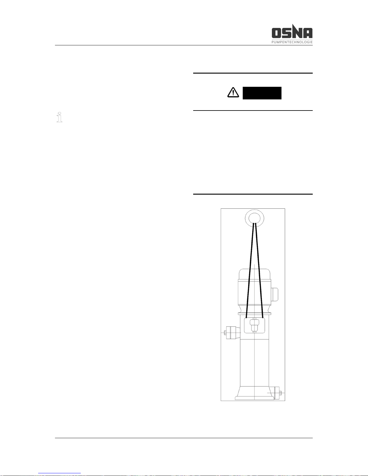
4.1.2 Lifting
DANGER
Risk of death or crushed limbs from falling
transported goods!
► Choose lifting equipment that is suitable for
the total weight to be transported.
► Do not stand under suspended loads.
Figure 4: Lifting a CVP centrifugal pump
Page 16
4 Transport and intermediate storage
14 CVP High-Pressure Centrifugal Pump
4.2 Intermediate storage
Ensure during intermediate storage that the
pump is not exposed to any weather conditions
for a long period of time. If the pump is decommissioned for a longer period of time (approximately 2 to 3 months), ensure that it is fully drained. (→ 6.2 Decommissioning, pg 24)
4.3 Storage
NOTICE
Material damage due to incorrect storage!
► Ensure that the pump is correctly stored.
1. Close all openings with blank flanges,
blind plugs or plastic covers.
2. Ensure that the storage area meets
the following conditions:
–
dry
–
free of frost
–
free of vibrations
3. Rotate the shaft once per month by
several rotations.
NOTICE
Damage to bearings due to high water
pressure or splashing water!
► Do not use water jets or steam jet cleaners
to clean the bearing areas and motor.
NOTICE
Damage to seals due to incorrect cleaning
agent!
► Ensure that the cleaning agent does not
corrode the seals.
1. Choose the cleaning agent according
to the area of use.
2. Dispose of preservatives in line with
the applicable local regulations.
3. When storing for longer than 6
months:
–
Check all elastomers (round seals,
shaft seal rings, gaskets and gland
packing) for elasticity, and replace
if necessary.
Page 17
4 Transport and intermediate storage
CVP High-Pressure Centrifugal Pump 15
4.4 Disposal
Plastic parts may be contaminated by toxic
or radioactive pumping media. If this is the
case, cleaning is not sufficient.
WARNING
Risk of poisoning and environmental damage from pumping medium!
► Use personal protective equipment when
performing work on the pump.
► Before disposing of the pump:
–
Collect any remaining pumping
medium in the pump, and dispose
of it in line with the locally valid
regulations.
–
Neutralize any pumping medium
residues in the pump.
► Dispose of the pump in line with the appli-
cable local regulations.
Page 18
5 Assembly and installation
16 CVP High-Pressure Centrifugal Pump
5 Assembly and installation
NOTICE
Material damage due to contamination!
► Only remove covers, transport caps and
sealing caps immediately before connecting
the pump to the pipelines.
CAUTION
Ensure compliance with all safety specifications during installation and operation.
1. Please consult the manufacturer when
installing at altitudes over 1000 m
above mean sea level.
5.1.1 Preparing the installation location
► Ensure that the installation location meets
the following conditions:
–
pump is freely accessible from all
sides
–
sufficient space for installing/removing
piping, as well as for maintenance and
repair work, in particular for installing/removing the pump and motor
–
no effects from external vibrations on
the pump (bearing damage)
–
protection against frost
5.1.2 Preparing the base surface and
foundations
► Ensure that the base surface and founda-
tions meet the following conditions:
–
level
–
clean (no oils, dust or other contaminations)
–
foundations can support the weight of
the pump unit and all operating forces
–
stability of the pump unit ensured
5.2 Installation
5.2.1 Installing the pump
Prior to installation, remove the packaging (if
present) and check the pump for any transport
damage. Ensure that the installation area is
dry and free of frost.
CAUTION
Do not operate the pump in areas where
there is a risk of explosion. Ensure that the
pump is installed and connected in line
with the local regulations.
Page 19
5 Assembly and installation
CVP High-Pressure Centrifugal Pump 17
We recommend installing the pump on a
noise-insulating base, in order to prevent
transmission noises to parts of the building.
Provide an outlet for leakage fluid during
maintenance work.
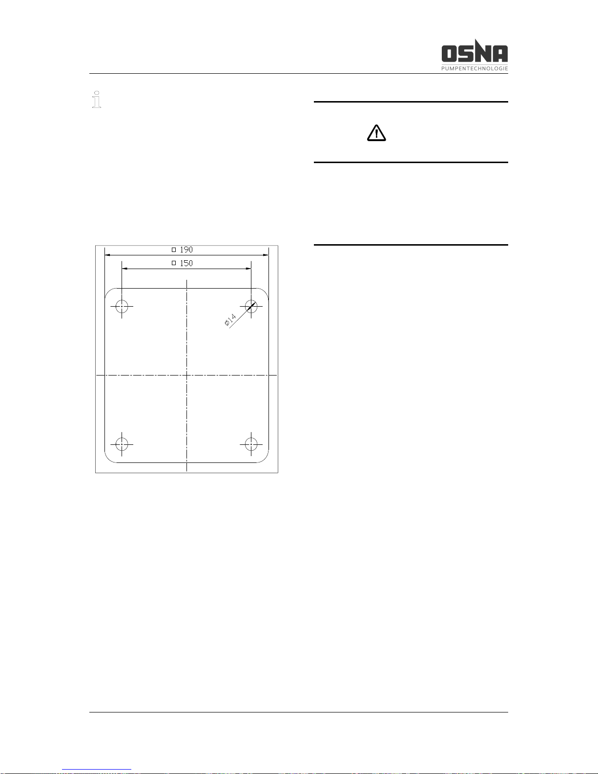
The pump's suction casing is shown as the
base, and must be secured free of tension to a
foundation using 4 M12 screws (à Figure 5,
pg 17).
Figure 5: Foundation plan for CVP 423 to 428
CAUTION
Install the pump in such a way that prevents flooding of building sections as the
result of a leak or when performing maintenance work.
5.2.2 Assembling the motor
Clean the motor shaft of any anti-rust agent
and remove the keys if present.
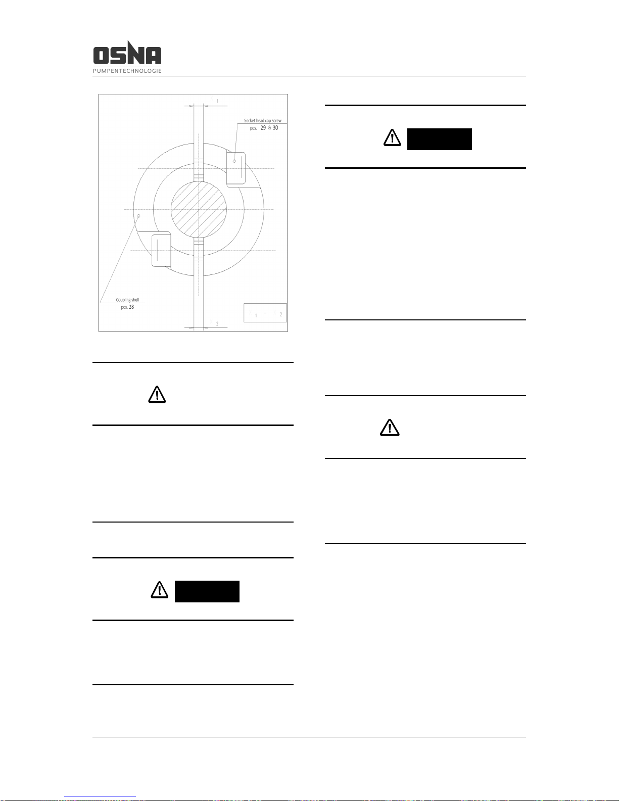
Remove the socket head cap screws (29 and
30) of the coupling shells (28), place the motor
on the delivery casing (20 or 26), and secure
with screws (see Table 14, pg 34). Manually
tighten the socket head cap screws on the
coupling shells slightly, ensuring that the gap
between the coupling shells is even (à Figure
6, pg 18). Please also refer to 6.1.3 Checking
direction of rotation, pg 22 for information on
checking the direction of rotation.
Page 20
5 Assembly and installation
18 CVP High-Pressure Centrifugal Pump
Figure 6: Overhead view of coupling
CAUTION
Incorrect direction of rotation on the pump
can lead to damage to the mechanical seal
and a reduction in performance. The pump
shaft must rotate clockwise, as seen from
the motor.
DANGER
Never operate the pump without the coupling guard.
DANGER
Risk of death due to rotating parts!
► Use personal protective equipment when
performing work on the pump.
► Prevent the keys from being slung away
when checking the direction of rotation.
► Ensure sufficient clearance to rotating
parts.
5.2.3 Electrical connection
CAUTION
Electrical connection must be carried out
by a specialist electrician, in line with the
specifications of the local energy supplier
or the VDE.
Install a motor protection switch to protect the
motor.
Page 21
5 Assembly and installation
CVP High-Pressure Centrifugal Pump 19
5.2.4 Adjusting the pump rotor
The rotor is not set on pumps that are fitted
with an electric motor ex-works.
Only drive CVP pumps with electric motors
that have a fixed bearing that cannot be shifted
from the B side to the A side.
Setting the rotor requires a fitting lever, a
marking tool, a power drill, a screwdriver and a
hexagonal socket wrench.
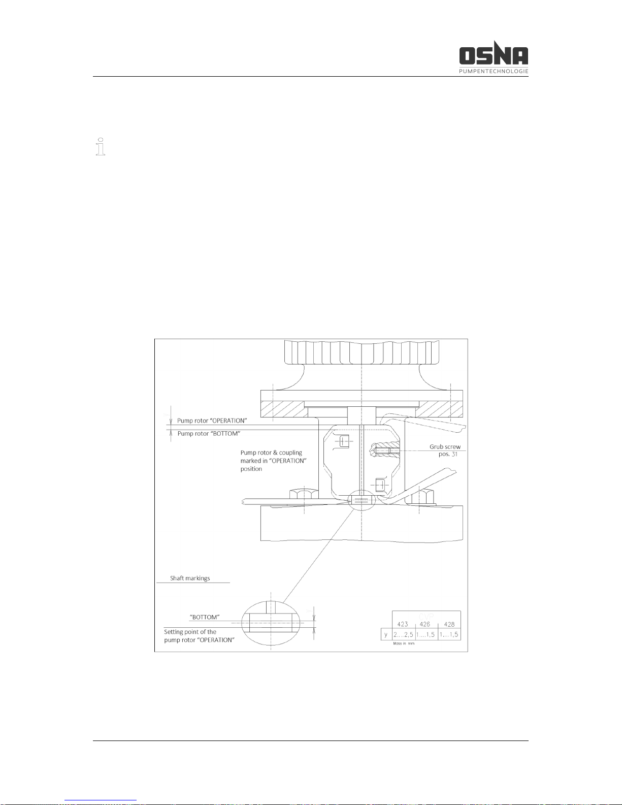
1. Press the pump rotor down together
with the coupling shells until the impel-
lers are in axial contact with the wear
plate. Mark the pump shaft.
2. Raise the pump rotor with the coupling
shells by the "y" dimension (à Figure
7, pg 19) and mark the pump shaft.
3. Evenly tighten the socket head cap
screws (29 and 30) (à Figure 6, pg 18
and Figure 7, pg 19).
4. Check the pump rotor setting.
5. Drill a hole in the motor shaft and secure the coupling shells against axial
shift with a grub screw (31).
Figure 7: Adjusting the pump rotor
Page 22
5 Assembly and installation
20 CVP High-Pressure Centrifugal Pump
5.3 Pipelines
Determine the nominal widths of the pipelines,
taking the local conditions into account. To
keep flow losses to a minimum, avoid sudden
constrictions and sharp bends. Route pipelines
free of tension and pressure tight. Install them
in a way that prevents forces and torques being transferred to the pump. Never use the
pump as an anchor point for the pipeline.
Fit the suction pipe rising to the pump and the
inlet pipe declining to the pump, in order to
prevent the formation of air bubbles. Support
the pipes immediately before the pump, and
connect without tension. Ensure that the
weight of the pipes does not strain the pump. If
using short pipes, the nominal widths must be
at least equal to those of the pump connections. If using long pipelines, determine the
cost-effective nominal width on a case-by-case
basis.
Taper pieces to larger nominal widths should
have an extending angle of approx. 8° to prevent increased pressure losses. Install check
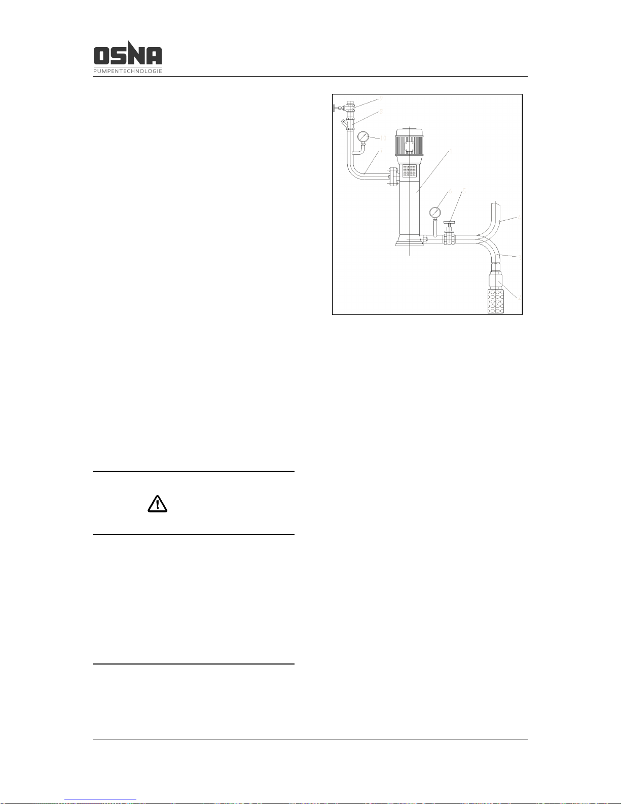
valves and shut-off devices depending on the
type of system and pump (à Figure 8, pg 20).
Take appropriate measures to compensate
any expansions of the pipelines caused by
temperature influences, in order to avoid
straining the pump with forces and torques.
CAUTION
Before commissioning new systems, the
tanks, pipelines and connections must be
thoroughly cleaned, flushed and blown
through. Welding beads, scales and other
contaminations often only fall off after a
longer period of time. Ensure that they are
kept away from the pump by fitting a
strainer in the suction pipe.
Figure 8: Functional and operating elements
Key:
1 Centrifugal pump
2* Foot valve with suction/inlet strainer
3* Suction pipe
4* Inlet pipe
5* Shut-off valve
6* Pressure gauge
7* Delivery pipe
8* Check valve
9* Control fitting
10* Pressure gauge
* not included in delivery
Page 23

5 Assembly and installation
CVP High-Pressure Centrifugal Pump 21
Suction or inlet pipe
(à Figure 8, pg 20, 3 and 4)
Keep the suction pipe as short as possible,
and route it in such a way that it is constantly
rising to the pump. Route the inlet pipe constantly declining to the pump.
Provide a draining mechanism at the lowest
point of the inlet pipe during inlet operation.
The CVP 428 requires a suction or inlet
pipe of at least R 2“.
Foot valve
(à Figure 8, pg 20, 2)
The foot valve keeps the suction pipe filled
with pumping medium.
Inlet sieve or strainer
(à Figure 8, pg 20, 11)
An inlet sieve or strainer protects the pump
against large-grain contaminations.
Monitoring fitting
(à Figure 8, pg 20, 6)
Monitoring fittings are required to monitor the
suction and inlet pressure. Monitoring valves
help monitor the operating data.
Shut-off valve
(à Figure 8, pg 20, 5)
A shut-off valve is used to block the pipe during assembly. The shut-off valve must be fully
opened when the pump is in operation.
Delivery pipe
(à Figure 8, pg 20, 7)
Control fitting
(à Figure 8, pg 20, 9)
A control fitting is always required to regulate
the pump power and block the pipeline during
assembly work.
Check valve
(à Figure 8, pg 20, 8)
A check valve is always required to protect the
pump.
Page 24
6 Commissioning/decommissioning
22 CVP High-Pressure Centrifugal Pump
6 Commissioning/
decommissioning
6.1 Commissioning
6.1.1 Determining the pump configuration
► Determine the pump configuration
6.1.2 Filling the pump
CAUTION
Check that there is enough water in the well
or feed tank.
Do not operate the pump without water. Dry
running can lead to damage to the pump.
WARNING
Risk of poisoning or injury due to hazardous pumping media!
► Collect any escaping pumping medium
safely and dispose of in an environmentally
friendly way.
NOTICE
Material damage due to dry running!
► Ensure that the pump is properly filled.
6.1.3 Checking direction of rotation
CAUTION
Incorrect direction of rotation on the pump
can lead to damage to the mechanical seal
and a reduction in performance. The pump
shaft must rotate clockwise, as seen from
the motor.
The cast direction of rotation arrow on the
pump indicates the specified direction of rotation.
Before checking the direction of rotation, secure the pump against activation.
Page 25
6 Commissioning/decommissioning
CVP High-Pressure Centrifugal Pump 23
DANGER
Risk of death due to rotating parts!
► Use personal protective equipment when
performing work on the pump.
► Prevent the keys from being slung away
when checking the direction of rotation.
► Ensure sufficient clearance to rotating
parts.
After checking the direction of rotation, ensure
that all safety and protective mechanisms are
reinstalled and reactivated.
DANGER
Never operate the pump without the coupling guard.
6.1.4 Starting the pump
Pump correctly installed and connect-
ed
Motor correctly installed and connect-
ed
All connections established, sealed
and free of tension
All safety mechanisms installed and
function tested
Pump correctly prepared, filled and
vented
DANGER
Risk of injury due to running pump!
► Do not touch the running pump.
► Do not perform any work on the running
pump.
DANGER
Risk of poisoning or injury due to spurting
pumping medium!
► Use personal protective equipment when
performing work on the pump.
Page 26
6 Commissioning/decommissioning
24 CVP High-Pressure Centrifugal Pump
NOTICE
Material damage due to dry running!
► Ensure that the pump is properly filled.
NOTICE
Open the suction-side fitting, and do not
use it to control the flow rate. Do not close
the pressure-side fitting!
0.1 MPa = 1 bar ≈ 10 m
6.2 Decommissioning
DANGER
Risk of injury from hazardous pumping
media!
► Collect any escaping pumping medium
safely and dispose of in an environmentally
friendly way.
► Take the following measures in the event of
operating interruptions:
Pump to be Measure
Shut down for
longer period
► Take measures according to
the pumping medium
Drained
► Close suction and delivery-side
fittings.
Disassembled
► Deactivate motor and secure
against unauthorized reactivation.
Put into storage
► Observe storage measures
(→ 4.3 Storage, pg 14).
Table 8: Measures in the event
of operational interruption
Flow medium
behavior
Duration of operating inte
r-
ruption (depending on process)
short
long
Solid components settle
► Flush
pump.
► Flush
pump.
Solidified/frozen,
non-corrosive
► Heat or
drain pump
and containers.
► Drain
pump and con-
tainers.
Solidified/frozen,
corrosive
► Heat or
drain pump
and containers.
► Drain
pump and con-
tainers.
► Apply pre-
servative to
pump and con-
tainers.
Remains fluid,
non-corrosive
– –
Remains fluid,
corrosive
–
► Drain
pump and con-
tainers.
► Apply pre-
servative to
pump and con-
tainers
Table 9: Measures depending on the behavior
of the pumping medium
Drain the pump completely if shutting down for
a longer period (approx. 2 - 3 months), or if
there is a danger of frost.
Page 27
6 Commissioning/decommissioning
CVP High-Pressure Centrifugal Pump 25
NOTICE
This work must be carried out by a specialist service provider.
CAUTION
Disconnect the pump from the electricity
supply if shutting down for a longer period.
6.2.1 Draining the pump and protecting
against frost
The pump must be drained if there is a danger
of frost. A pump that remains empty over a
longer period must be preserved.
6.3 Recommissioning
CAUTION
The pump must move easily for recommissioning.
Check that the pump moves easily before recommissioning.
If the pump was preserved after decommissioning, flush it thoroughly before recommissioning.
Perform all further work steps in line with 6.1
Commissioning, pg 22.
Take the following measures before recommissioning following operating interruptions of
> 1 year:
Shut down
time
Measure
> 1 year
► Check visually for leaks
> 2 years
► Replace elastomer seals
(gaskets, round seals, shaft seal
rings and gland packings).
► Replace anti-friction bearings.
Table 10: Measures following longer shut down times
6.4 Mechanical seal
Mechanical seals are self-adjusting mechanical shaft seals that require no maintenance.
The mechanical seal must never run dry. Ensure therefore that the pump is filled.
Do not reinstall mechanical seals after removing them for inspection or maintenance. Replace them with new seals, or relap the contact
surface.
Page 28
7 Commissioning/decommissioning
26 CVP High-Pressure Centrifugal Pump
NOTICE
Material damage due to dry running!
► Ensure that the pump is properly filled.
Page 29
7 Maintenance and repair
CVP High-Pressure Centrifugal Pump 27
7 Maintenance and repair
7.1 General information
We can provide trained customer service
technicians for assembly and repair work.
Please present proof of the conveyed
goods upon request.
(DIN safety data sheet or clearance certificate)
DANGER
Risk of injury due to running pump!
► Do not touch the running pump.
► Do not perform any work on the running
pump.
WARNING
Risk of poisoning or injury due to hazardous pumping media!
► Use personal protective equipment when
performing work on the pump.
Ensure that the pump runs smoothly and quietly at all times. Maximum permitted room temperature 40 °C.
The mechanical seal displays only limited or
invisible leakage losses (in vapor form). It requires no maintenance.
The reserve pumps must be activated once
per week in order to ensure operational readiness. To do so, switch the reserve pumps on
and immediately off again. Monitor the function
of the additional connections.
The pump shaft is supported in the suction
casing in a zero-maintenance bearing shell
made from PTFE graphite. The pump shaft
and motor shaft are connected rigidly by
means of a muff coupling.
Ensure that the socket head cap screws of the
coupling shells are tightened at regular intervals. Perform an initial check after 50 operating
hours, and further checks after every 1,000
operating hours.
DANGER
Risk of death from electric shock!
► Only allow work on the electrical systems to
be carried out by a qualified electrician.
► Ensure that the supply of electricity is
switched off and secured against reactivation when performing all maintenance work.
Page 30
7 Maintenance and repair
28 CVP High-Pressure Centrifugal Pump
DANGER
Only perform the inspection when the system is switched off and secured.
7.2 Sending the pump to the manufacturer
ü Pump depressurized
ü Pump completely drained
ü Electrical connections disconnected
and motor secured against reactivation
ü Manometer removed together with
supply lines and holders
1. Only send pumps or individual components to the manufacturer together
with a verifiable and completely filled
out clearance certificate. Request a
clearance certificate from the manufacturer if required.
2. Using the following table, take the action required for returning the pump
according to the necessary repair.
Repair
Action for return
At customer
► Return defective component to manufacturer.
At manufacturer
► Flush pump.
► Send complete pump
(not disassembled) to manu-
facturer.
At manufacturer,
with guarantee
claim
► Only if using hazardous
pumping medium: flush pump.
► Send complete pump
(not disassembled) to manu-
facturer.
Table 11: Measures for return
Page 31
8 Faults and troubleshooting
CVP High-Pressure Centrifugal Pump 29
8 Faults and troubleshooting
Please consult the manufacturer should you
experience any faults that are not described in
the following table, or cannot be traced back to
the described causes.
In the following table, each potential fault is
given a number. Use this number to find the
corresponding cause and remedy in the troubleshooting table.
Fault
Number
Pump does not deliver 1
Flow rate too low 2
Flow rate too high 3
Pumping pressure too low 4
Pumping pressure too high 5
Pump runs noisily 6
Temperature of the anti-friction bearings
too high
7
Pump leaks 8
Motor power consumption too high 9
Table 12: Fault/number allocation
Fault number Cause Remedy
1 2 3 4 5 6 7 8 9
X - - - - - - - -
Inlet/suction pipe and/or pressure
pipe closed by fitting
► Open fitting.
- X - X - - - - -
Inlet/suction pipe not completely
opened
► Open fitting.
X X - X - X - - -
Inlet/suction pipe, pump or suction
strainer blocked or encrusted
► Clean inlet/suction pipe, pump or
suction strainer.
- X - X - X - - -
Cross-section of the inlet/suction
pipe too tight
► Enlarge cross-section.
► Clean suction pipe of encrustations.
► Fully open fitting.
X - - - - - - - -
Transport sealing cap not removed
► Remove transport sealing cap.
► Disassemble pump and check for
dry running damage.
- X - X - X - - -
Suction head too high: NPSH
pump
is greater than NPSH
system
► Increase inlet pressure.
► Consult manufacturer.
X - - - - X - - -
Inlet/suction pipe and pump not
correctly drained or not completely filled.
► Completely fill and drain pump
and/or pipeline.
X - - - - X - - -
Air pockets in inlet/suction pipe ► Install fitting for venting.
► Correct pipeline routing.
X X - X - X - - -
Air sucked in ► Seal source of fault.
X X - X - X - - -
Gas component too high: pump
cavitated
► Consult manufacturer.
- X - X - X - - - Temperature of pumping medium
too high: pump cavitated
► Increase inlet pressure.
► Reduce temperature.
► Consult manufacturer.
Page 32
8 Faults and troubleshooting
30 CVP High-Pressure Centrifugal Pump
Fault number Cause Remedy
1 2 3 4 5 6 7 8 9
- X - X - - - - -
Geodetic delivery head and/or
pipeline resistance too high
► Remove deposits in pump and/or
pressure pipe.
► Install larger impeller and consult
manufacturer.
- X - - X X - - -
Pressure-side fitting not opened
far enough
► Open pressure-side fitting.
X X - - X X - - -
Pressure line blocked ► Clean pressure line.
X X - X - X - - -
Incorrect direction of rotation on
pump
► Swap any two phases on motor.
X X - X - - - - -
Speed too low ► Compare required motor speed with
pump type plate. Replace motor if necessary.
► Increase speed if possible.
- X - X - X X - -
Pump components worn ► Replace worn pump components.
- - X X - X - - X
Pressure-side fitting opened too
far
► Throttle with pressure-side fitting.
► Machine down impeller. Consult
manufacturer and adjust impeller diameter.
- - X - - X - - X
Geodetic delivery head, pipeline
resistance and/or other resistances lower than designed
► Throttle flow rate with pressure-side
fitting. Observe minimum flow rate here.
► Machine down impeller. Consult
manufacturer and adjust impeller diameter.
- - X - X - - - -
Viscosity lower than indicated ► Machine down impeller. Consult
manufacturer and adjust impeller diameter.
- - X - X X X - X
Speed too high ► Compare required motor speed with
pump type plate. Replace motor if necessary.
► Reduce speed if possible.
- - X - X X - - X
Number of stages too high ► Throttle flow rate with pressure-side
fitting. Observe minimum flow rate here.
► Install pump with lower number of
stages.
X X - X - X - - -
Impeller imbalanced or blocked ► Disassemble pump and check for
dry running damage.
► Clean impeller.
- X - X - X - - - Hydraulic pump components dirty,
sticky or encrusted
► Disassemble pump.
► Clean components.
Page 33
8 Faults and troubleshooting
CVP High-Pressure Centrifugal Pump 31
Fault number Cause Remedy
1 2 3 4 5 6 7 8 9
- - - - - - X - X
Defective anti-friction bearing in
motor
► Replace anti-friction bearing.
- - - - - - X - -
Lubricant: too much, too little or
not suitable
► Reduce, increase or replace lubricant.
- - - - - - - X -
Tie bolts not tightened correctly ► Tighten tie bolts.
- - - - - - - X -
Mechanical seal worn ► Replace mechanical seal.
- - - - - - - X -
Defective casing seal ► Replace casing seal.
- - - - - - - X -
Shaft sleeve penetrated ► Replace shaft sleeve and round
seal.
- - - - - X X X X
Pump under tension ► Check pipeline connections and
pump fastening.
► Check coupling alignment.
► Check support foot fastening.
- - - - - X X - -
Coupling incorrectly aligned ► Align coupling.
- X - X - X - - X
Motor runs on 2 phases ► Check fuse and replace if necessary.
► Check wire connections and insulation.
Table 13: Troubleshooting table
Page 34
9 Appendix
32 CVP High-Pressure Centrifugal Pump
9 Appendix
9.1 Service, spare parts, accessories
Please note in particular that spare parts and
accessories not delivered by the manufacturer
are also not checked and approved by the
manufacturer. The installation and/or use of
such products can therefore, under certain circumstances, have a negative effect on the
properties of the centrifugal pump specified in
the design. This can in turn jeopardize safety.
Any liability and guarantee on the part of OSNA for damages resulting from the use of nonoriginal spare parts and accessories is excluded.
Any faults that cannot be rectified by the owner
may only be rectified by OSNA customer service or specialist service providers. Please
provide a precise description of the fault, so
that our service technician can prepare and
bring the required spare parts. You can reach
our customer service via the address on the
last page.
Spare parts can be ordered via specialist retailers. Please refer to the type plate for the
type designation.
In the event of any guarantee claims, please
provide the machine number on the housing.
The following spare parts diagrams are intended solely to ease the process of finding and
procuring the spare parts.
WARNING
Do not use the spare parts diagrams as assembly instructions.
Notes on ordering spare parts:
In order to prevent incorrect deliveries, please
ensure that the information you provide when
ordering is as precise as possible:
· Type designation
· Designation
· Required quantity
· Required shipping method (e.g. post,
freight, express freight, courier delivery)
· Precise delivery address
Page 35
9 Appendix
CVP High-Pressure Centrifugal Pump 33
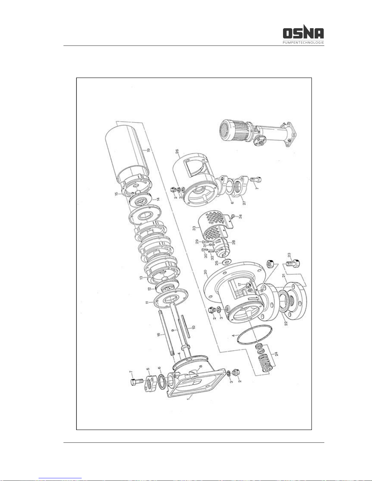
9.2 Individual parts of the CVP centrifugal pump
Figure 9: Explosion diagram of the CVP centrifugal pump
Page 36
9 Appendix
34 CVP High-Pressure Centrifugal Pump
Item Designation Item Designation
1 Suction casing
2 Screwed plug
3 Joint ring
4 O-Ring
5 Flange
6 Gasket
7 Hexagon head bolt
8 Bearing shell
9 Pump shaft with spacer ring
10 Key (round)
11 Wear plate
12 Impeller
13 Diffuser
14 Impeller (top)
15 Grub screw
16 Tie bolt
17 Cap nut
18 Screw lock
19 Stage casing
20 Delivery casing
21 Flange
22 Gasket
23 Hexagon head bolt with nut
24 Mechanical seal
25 Thrower
26 Delivery casing
27 Flange
28 Muff coupling, split
29 Socket head cap screw
30 Socket head cap screw
31 Grub screw
32 Locking sleeve
33 Coupling guard
34 Socket head cap screw
Table 14: Parts list of the CVP centrifugal pump
Page 37
9 Appendix
CVP High-Pressure Centrifugal Pump 35
9.3 Declaration of Conformity as per EC Directive 2006/42/EC, Annex IIA
We hereby declare under our sole responsibility as manufacturer that the following machine series of
the type, as well as the configurations distributed by us, conform to the relevant specifications of the
EC Machinery Directive 2006/42/EC.
Designation:
CVP 423, 426, 428
Pump number: 172000 - 210000
The machine also corresponds with the following directives published in the Official Journal of the European Union:
· Niederspannungsrichtlinie (2014/35/EU)
· EMV-Richtlinie (2014/30/EU)
· Ökodesignrichtlinie (2009/125/EG)
This declaration shall cease to be valid in the event of any modifications to the machine and/or its protective mechanisms not agreed with us and approved in writing.
Applied harmonized standards and their references in the Official Journal of the European Union:
· DIN EN 809 : 2012
· DIN EN ISO 12100 : 2011
· DIN EN ISO 13732 : 2008
· DIN EN ISO 13849-1 : 2008
· DIN EN ISO 13857-1 : 2008
· DIN EN 60034 : 2007
· DIN EN 60204-1 : 2009
· DIN EN 55024 : 2011
Authorized representative for the composition of technical documentation for OSNA-Pumpen GmbH:
Mr. Rik Arensmann
Brückenstrasse 3
49090 Osnabrück, Germany
Osnabrück, 12.01.2017 _______________________________
Rik Arensmann
Technical Director/QM Officer
Page 38

9 Appendix
36 CVP High-Pressure Centrifugal Pump
9.4 Clearance Certificate
Please copy and send with the pump.
Clearance Certificate
Legal provisions oblige all businesses to protect their employees, other persons and the environment
from damaging effects when handling hazardous substances. Products and their components may
therefore only be repaired or inspected when the following declaration has been fully and correctly
filled out and singed by an authorized and qualified specialist. Please provide the necessary information should safety measures on the part of the system owner still be required despite complete
draining and cleaning. This clearance certificate is part of the repair or inspection order.
We hereby assure that the enclosed device
Type: _______________________________________________________________
Serial no.: _______________________________________________________________
is free of substances that are hazardous to health. No special safety measures are required for further
handling. The device was fully drained and thoroughly cleaned inside and outside before dispatch.
Company/institute: _______________________________________________________________
Address: _______________________________________________________________
Town/city, ZIP code: _______________________________________________________________
Phone: _______________________________________________________________
Name: _______________________________________________________________
Position: _______________________________________________________________
Date: _______________________________________________________________
Signature, company stamp: ________________________________________________________
Page 39

9 Appendix
CVP High-Pressure Centrifugal Pump 37
Notes
_________________________________________________________________________________
_________________________________________________________________________________
_________________________________________________________________________________
_________________________________________________________________________________
_________________________________________________________________________________
_________________________________________________________________________________
_________________________________________________________________________________
_________________________________________________________________________________
_________________________________________________________________________________
_________________________________________________________________________________
_________________________________________________________________________________
_________________________________________________________________________________
_________________________________________________________________________________
_________________________________________________________________________________
_________________________________________________________________________________
_________________________________________________________________________________
_________________________________________________________________________________
_________________________________________________________________________________
_________________________________________________________________________________
_________________________________________________________________________________
_________________________________________________________________________________
_________________________________________________________________________________
_________________________________________________________________________________
_________________________________________________________________________________
_________________________________________________________________________________
_________________________________________________________________________________
_________________________________________________________________________________
_________________________________________________________________________________
_________________________________________________________________________________
_________________________________________________________________________________
_________________________________________________________________________________
_________________________________________________________________________________
_________________________________________________________________________________
_________________________________________________________________________________
_________________________________________________________________________________
_________________________________________________________________________________
Page 40

PUMPS
SYSTEMS
WATER TREATMENT
ENGINEERING
SERVICES
OSNA-Pumpen GmbH Your no. 1 choice for the solution you need:
Brückenstrasse 3
49090 Osnabrück, Germany - Consulting - Training
Phone: +49 541 1211 – 0 - Planning - Maintenance
Fax: +49 541 1211 – 220 - Project management - Repair
Internet: http://www.osna.de - Assembly
E-mail: [email protected]
OSNA customer service Tel.: +49 541 1211 – 254
Emergency service Tel.: +49 171 4151 – 674
 Loading...