

OSI Security Devices OMNILOCK OM100, OMNILOCK OM500, OMNILOCK OM300 Installation Instructions Manual
DEVICES
FOR USE WITH THIS PRODUCT.
BOX
THUMB TURN
WITH CAM
ASSEMBLY
KEY
GROUND
ELECTRONICS MODULE
SPINDLE & SPRING
3/4” THICK
DOOR (2
-
REQD)
INNER INSERT
ASSEMBLY
PG. 1 OF 8
AND OM500 SERIES
SCREW
DOOR HANDLING
RIGHT HAND SHOWN
DOOR HAND DETERMIN
ED FROM OUTSIDE
HAND
RIGHT
RIGHT HAND
LEFT HAND
SECURITY
OMNILOCK
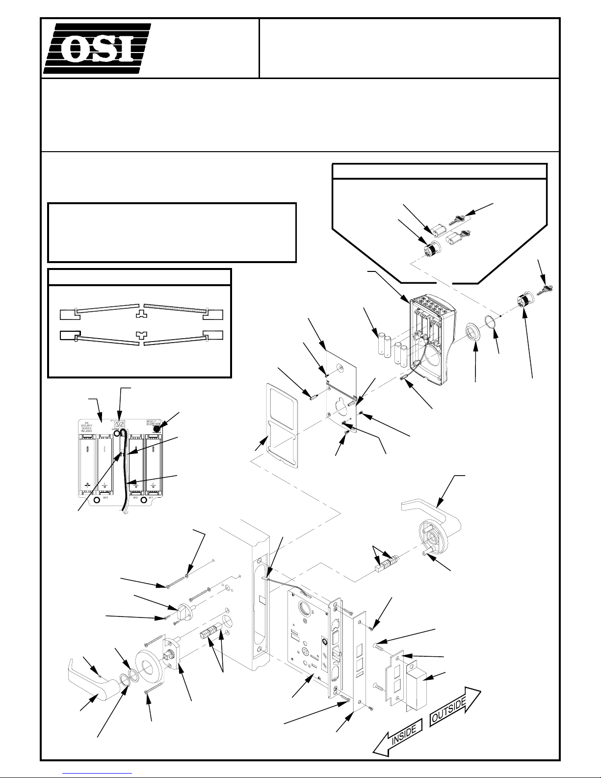
INSTALLATION INSTRUCTIONS FOR OM100, OM300,
ACCESS CONTROL SYSTEMS
LOCKSETS USING FALCON
WARNING: THIS PRODUCT IS NOT WARRANTED FOR
OUTDOORS USE!
NOTE: A DOOR-CLOSER IS HIGHLY RECOMMENDED
THIS PRODUCT IS NORMALLY FACTORY-PACKED
FOR RIGHT-HAND 1-3/4” TO 2” THICK DOORS.
TO CHANGE HAND OF LOCK, SEE
LEFT
REVERSE
BEVEL
CPU PC
BOARD
ASSEMBLY
MOTOR
CONNECTOR
SCREW, PAN HEAD TORX
#8-32X1-1/2” FOR 2” THICK DOOR
#8-32X1-1/4” FOR 1-
SCREW, FLAT
HEAD #6X1/2”
(2-REQD)
SET
INSTRUCTION SECTION 2.
INSIDE
OUTSIDE
INSIDE
OUTSIDE
TERMINAL BLOCK
(FOR REMOTE SWITCH)
WASHER
COLLAR
NYLON
HAND
REVERSE
BEVEL
RESET
BUTTON
RED
WIRE
BLACK
WIRE
SPINDLE & SPRING
SEMS #4-40X1/4”
STANDOFF
#8-32X1”
(2-REQD)
GASKET
™
BATTERY
COVER
PAN HEAD
LOCK
CONNECTOR
(Routes through
the slot in the
Door)
NON-WEATHERIZED, MORTISE
LM SERIES LOCKS (LEVER)
SCREWS,
FLAT HEAD
#8-32X3/8”
LG (2-REQD)
INTERCHANGEABLE CORE (I.C.)
I.C. CORE
(NOT SUPPLIED)
I.C. CYLINDER
WITH CA M
HOUSING
AA ALKALINE
BATTERY, 1.5V
(4-REQD)
U
L
ELECTRONIC AL LY CONT R O LLE D
SINGLE POIN T LOCK OR LATCH
BACK
PLATE
SPRING
ASSEMBLY
SCREW
FLAT HEAD
#8X2-1/4”
(2-REQD)
SCREW
PAN HEAD
#6-32X1/4”
SCREW
FLAT HEAD
#12 X 1”
(2-REQD)
CONTROL KEY
(NOT SUPPLIED)
CYLINDER
COLLAR
CONNECTOR
OUTER TRIM
ASSEMBLY
SCREW
POST
STRIKE
STRIKE
WAVY
WASHER
CYLINDER
INSIDE
LEVER
SCREW, FLAT
WASHER
HEAD #10-32 X 2”
(2 REQD)
ASSEMBLY
LOCK
SCREW
FLAT HEAD
#12 X 1” (2-REQD)
FACE
PLATE
SECTION 1: CHECK OPERATION
PG. 7 OF 8
PG. 2 OF 8
FIG.12
FIG.1
CONNECTOR
MOUNTING SCREW
(2 REQD)
CONNECTOR
WASHER
(2 REQD)
FIG.11
COLLAR
CYLINDER
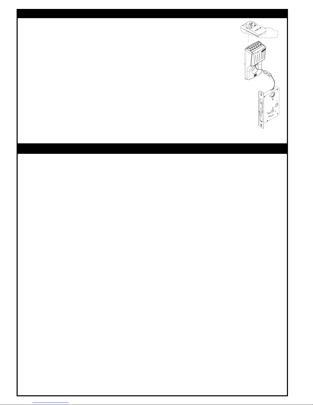
a. Connect the Lock Connector to the Electronics Module Connector so that the Red Wires ar e aligne d.
b. Verify proper operation of the System by entering the Default Master Code 5011234. The System
c. Verify communication with the WP4000 Printer.
d. Disconnect the Lock Connector.
Refer to Fig.1.
will flash three times to indicate the Battery level and unlock. It will remain unlocked for approximately
5 seconds before flashing red and relocking. While unlocked, check for proper operation of the Lock
using the Outer Trim Assembly and Spindle.
1. Turn on the Printer and Position it over the Keypad so that the Infrared Port of the Printer is aligned
over the Infrared Port of the System.
2. Enter the Default Master Code 5011234 at the Keyboard and then enter 99.
3. The Printer will print some System data and then present a menu of choices.
4. Enter 0 (END) at the Keypad. The System will flash red and re-locked.
5. If the system malfunctions, remove the Battery Cover and check for proper orientation and seating
of the Batteries and Motor Connector. Also ensure that the wires are not pinched. Reset the
electronics by pressing and holding the Reset Button on the circuit board until the light on the
Keypad flashes green, approximately three to five seconds. The System will go through a self-test
and flash green 5 times. Any red flash indicates an electronics or motor problem. If all flashes are
green, repeat Steps b and c.
SECTION 2: ADJUST THE LOCK HAND
This section is only required if the lock hand, as received, does not meet your requirements. The Lock is normally
2-1
preset for a right hand door. Verify the hand of the Lock and if required, Change the hand of the Lock as follows, after
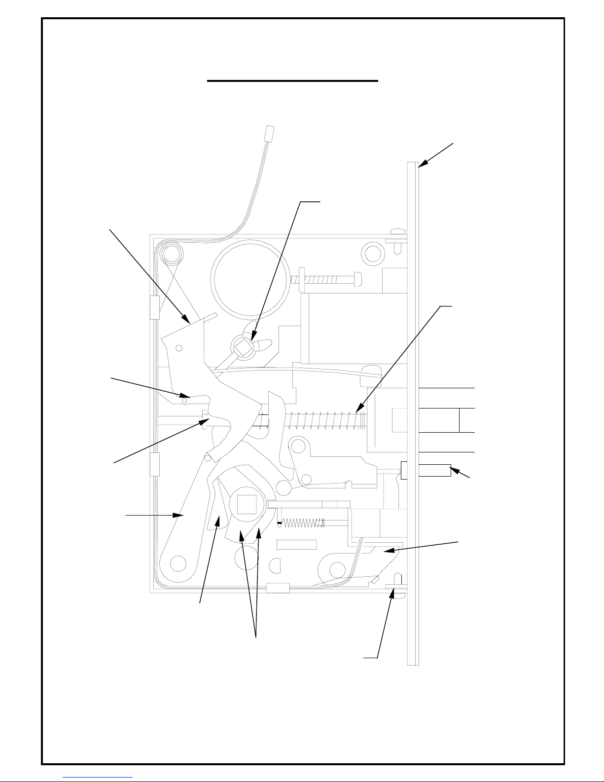
checking per Section 1. Refer to Fig.2.
NOTE: If the Lock has a Dead Bolt, it must be in the retracted position when reversing hand.
a. REMOVE COVER
1. Remove the four Cover Retaining Screws and slowly remove the Cover from the Case.
b. REVERSE LATCH BOLT ASSEMBLY
1. Lift out the Cylinder Retract Lever, if included.
2. Lift out the Upper Retract Arm, if included.
3. Compress the Latch Bolt Spring toward the Face Plate to clear the Latch Bolt Guide Seat. Lift out and invert
the Latch Bolt Assembly. Place the Latch Bolt Spring into the Latch Bolt Guide Seat.
NOTE: Lower Retract Arm (below the Upper Retract Arm) must be between the Latch Bolt Foot and the Latch Bolt Guide.
c. REVERSE HUBS
1. To reverse, pull the Coupling toward the rear of the Case.
2. Lift out both Hubs together, invert as an assembly and replace.
3. Ease the Coupling back against the Hubs.
d. REASSEMBLE RETRACT ARM AND LEVER
1. Replace the Upper Retract Arm so that the Arm fits into the space between the Latch Bolt Foot and the
2. Replace the Cylinder Retract Lever so that it straddles the Dead Bolt Pin.
3. Replace the Cover guiding the "T" Turn Hub into the Cover hole. Depress the Latch Bolt to clear the Foot.
NOTE: A Phillips head screwdriver inserted through the Cover into the "T" Turn Hub will retain the Hub and Cylinder Retract
Lever in proper location while replacing the Cover.
e. REPLACE THE COVER RETAINING SCREWS.
f. REVERSE DEADLOCKING BAR
1. Remove the Face Plate. Remove the Deadlocking Bar, reverse it and replace it back into the Assembly.
2. Replace the Face Plate.
NOTE: The Concave Face of the Deadlocking Bar must be on the same side of the Door as the Beveled Face on the Latch
Bolt. If this condition is not met, the Latch Bolt will be blocked from being able to be depressed as it comes into
contact with the Strike.
Coupling.
(Push against Blocker Assembly to allow Deadlocking Bar to be easily inserted)
PG. 3 OF 8
FOOT
RETRACT
ARM
COUPLING
LATCH BOLT
HUB
HUB
LOCK FRONT
SCREW
ASSEMBLY
FACE PLATE
FIG.2
LOCK ASSEMBLY
“T” TURN
CYLINDER
RETRACT
LEVER
SPRING
DEAD BOLT
PIN
DEAD LOCKING
BAR
UPPER
BLOCKER
 Loading...