

Page 1

MAX-12TG/MAX-12TG-X
MAX-12TG-P/MAX-12TG-PX
It is of vital importance, before attempting to operate your
engine, to read the general 'SAFETY INSTRUCTIONS
AND WARNINGS' section on pages 2-5 of this booklet and
to strictly adhere to the advice contained therein.
Also, please study the entire contents of this instruction
manual, so as to familiarize yourself with the controls and
other features of the engine.
Keep these instructions in a safe place so that you may
readily refer to them whenever necessary.
It is suggested that any instructions supplied with the
vehicle, radio control equipment, etc., are accessible for
checking at the same time.
JAPAN
SAFETY INSTRUCTIONS AND
WARNINGS ABOUT YOUR O.S. ENGINE
ENGINE CONSTRUCTION, NOTES WHEN
APPLYING AN ELECTRIC STARTER
INSTRUCTIONS
BASIC ENGINE PARTS
TOOLS, ACCESSORIES, etc.
STANDARD ACCESSORIES
CARBURETOR CONTROLS,
INSTALLATION OF THE CARBURETOR
NOTES CONCERNING THE RECOIL STARTER
GLOWPLUG
2-5
6-7
8
10-11
13-15
CONTENTS
ENGINE INSTALLATION
STARTING THE ENGINE &
RUNNING-IN ('Breaking-in)
FINAL ADJUSTMENT
9
12
16
17
TROUBLE SHOOTING
CARE AND MAINTENANCE
EXPLODED ENGINES VIEWS &
PARTS LIST
CARBURETOR EXPLODED VIEW &
PARTS LIST
O.S. GENUINE PARTS & ACCESSORIES
THREE VIEW DRAWING
1
18-19
20-26
27-30
31-34
35-37
38-45
46-49
50-52
53-56
Page 2
SAFETY INSTRUCTIONS AND WARNINGS ABOUT YOUR O.S. ENGINE
Remember that your engine is not a "toy", but a highly efficient internalcombustion machine whose power is capable of harming you, or others, if it is
misused. As owner, you, alone, are responsible for the safe operation of your
engine, so act with discretion and care at all times.
If at some future date, your O.S. engine is acquired by another person, we would
respectfully request that these instructions are also passed on to its new owner.
The advice which follows applies basically to ALL MODEL ENGINES and is
grouped under two headings according to the degree of damage or danger
which might arise through misuse or neglect.
WARNINGS
!
These cover events which might involve
serious (in extreme circumstances, even
fatal) injury.
WARNINGS
!
•
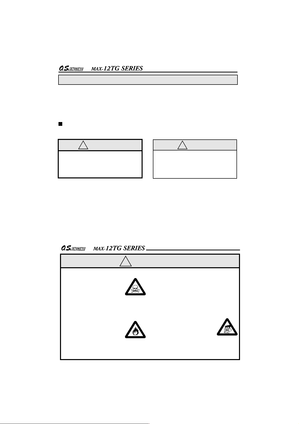
Model engine fuel is poisonous. Do not allow it to
come into contact with the
eyes or mouth. Always store
it in a clearly marked container and out of the reach
of children.
Model engine fuel is also
•
highly flammable. Keep it
away from an open flame,
excessive heat, sources of
sparks, or anything else
which might ignite it. Do not
smoke or allow anyone else
to smoke, near to it.
NOTES
!
These cover the many other possibilities,
generally less obvious sources of danger,
but which, under certain circumstances,
may also cause damage or injury.
2
•
Never operate your engine in an enclosed space. Model engines, like
automobile engines, exhaust deadly
carbon-monoxide. Run your engine
only in an open area.
Model engines generate
•
considerable heat. Do not
touch any part of your
engine until it has cooled.
Contact with the muffler
(silencer), cylinder head
or exhaust header pipe, in
particular, may result in a
serious burn.
3
Page 3
NOTES
!
This engine is intended for model cars.
Do not attempt to use it for any other
purpose.
Mount the engine in your model
securely, following the manufacturer's
recommendations, using appropriate
screws and locknuts.
Install an effective silencer (muffler).
Frequent close exposure to a noisy
exhaust (especially in the case of the
more powerful highspeed engines) may
eventually impair your hearing and such
noise is also likely to cause annoyance
to others over a wide area.
The wearing of safety glasses is also
strongly recommended.
Take care that the glowplug clip or
battery leads do not come into contact
with rotating parts. Also check that the
linkage to the throttle arm is secure.
For their safety, keep all onlookers
(especially small children) well back (at
least 20 feet or 6 meters) when
preparing your model for running.
Before starting the engine, always check
the tightness of all the screws and nuts
especially those of joint and movable
parts such as throttle arm. Missing
retightening the loose screws and nuts
often causes the parts breakage that is
capable of harming you.
4
NOTES
!
To stop the engine, fully retard the
throttle stick and trim lever on the transmitter, or, in an emergency, cut off the
fuel supply by pinching the fuel delivery
line from the tank.
Do not attempt to disassemble the recoil
starter of the 12TG-X and 12TG-PX.
If you do so, the very strong spring inside
will be suddenly ejected. This can be
very dangerous.
Do not extend the starter cord more than
40cm (16"). Do not abruptly release the
operating handle. Allow the cord to
rewind smoothly while still holding the
handle.
Pull the operating handle straight out
when starting the engine, so that the cord
does not rub against the vehicle body or
engine. This will help prevent the cord
from being damaged by abrasion or
engine heat.
Warning! Immediately after a glowplugignition engine has been run and is still
warm, conditions sometimes exist
whereby it is just possible for the engine to
abruptly restart if it is rotated over
compression WITHOUT the glowplug
battery being reconnected.
5
Page 4
ENGINE CONSTRUCTION
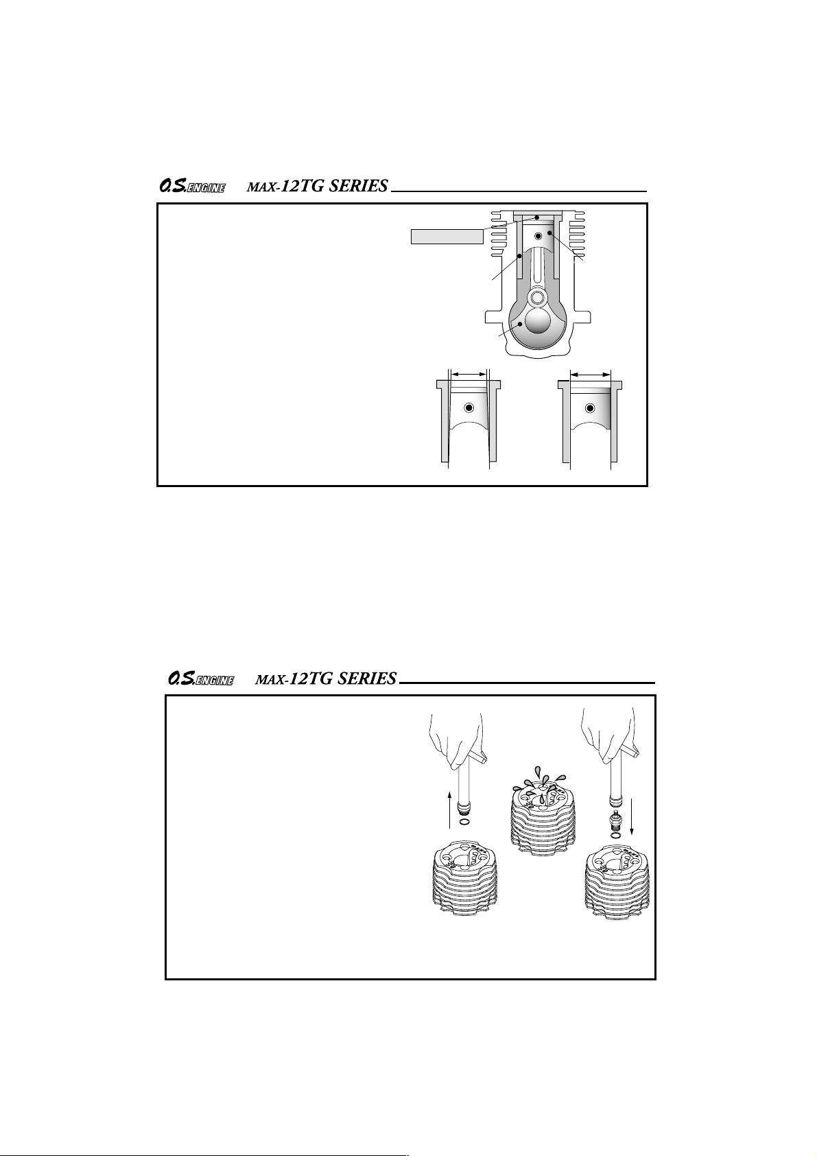
Near TDC
With this engine, the piston
will feel tight at the top of its
stroke (TDC) when the engine
is cold. This is normal. The
cylinder bore has a slight
taper. The piston and cylinder
are designed to achieve a
perfect running clearance
when they reach operating
temperature.
Cylinder Liner
Crankshaft
Slight taper
When the engine is cold.
6
Piston
When the engine is hot.
NOTES WHEN APPL YING
AN ELECTRIC STARTER
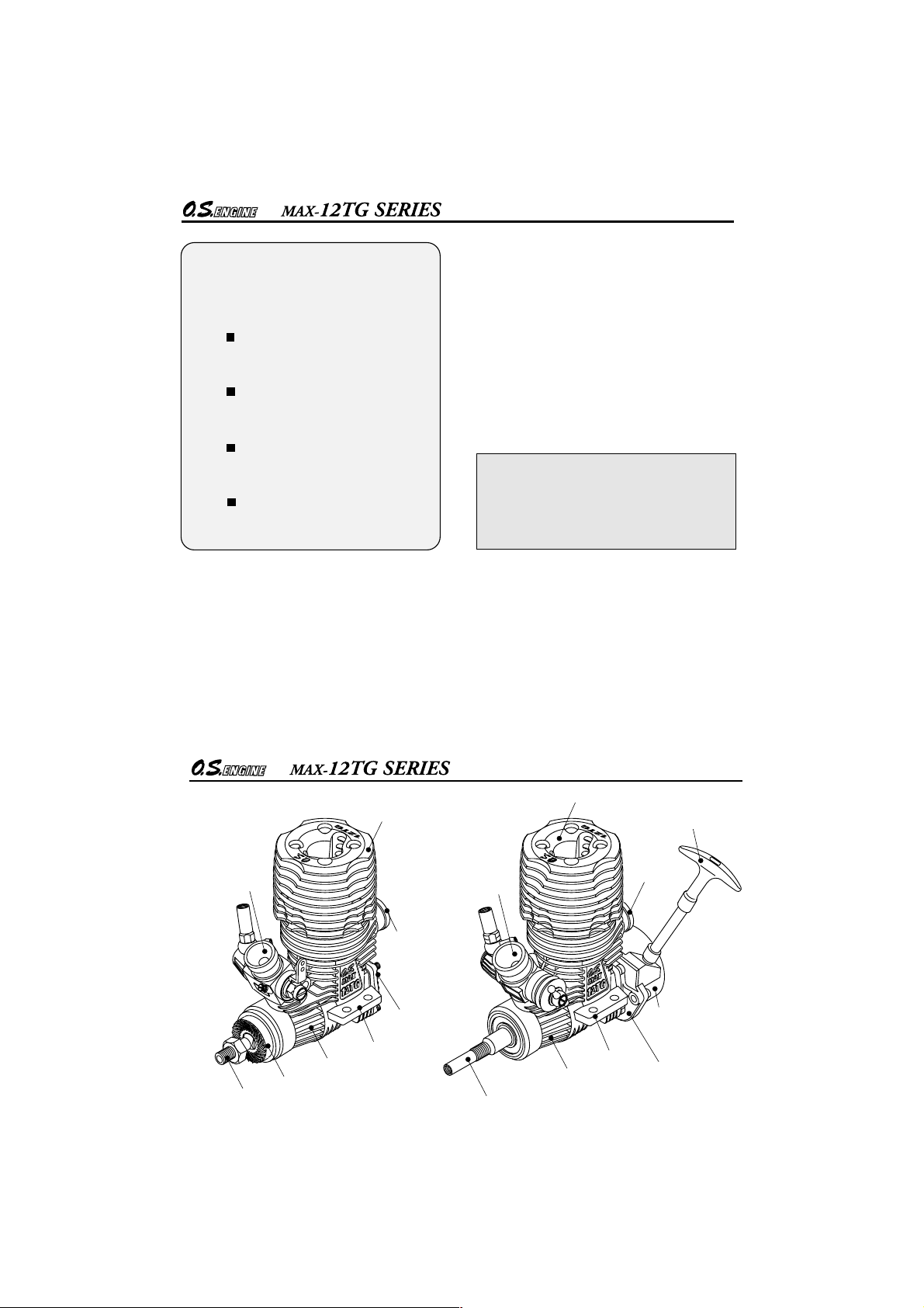
Do not over-prime. This could
cause a hydraulic lock and damage
the engine on application of the
electric starter.
If over-primed, remove glowplug,
close needle-valve and apply
starter to pump out surplus fuel.
Cover the head with a rag to
prevent any pumped out fuel from
getting into your eyes.
Remove the glowplug.
7
Pump out surplus fuel.
Install the glowplug.
Page 5
MAX-
12TG SERIES INSTRUCTIONS
This manual handles the following four
versions.
12TG
MAX with 12E carburetor
MAX-
12TG-X
with 12E carburetor
MAX-
12TG-P
with 12D carburetor
MAX-
12TG-PX
with 12D carburetor
The 12TG Series engines are developed for
1/10 scale R/C cars. They are rear exhaust
engines designed for sport use.
For easier handling newly designed 12E or
12D carburetor is equipped, and also No.8
glowplug is supplied. They have mild and
smooth accelerating characteristics which
are most suitable for sport runs.
Recoil starter incorporated versions which
eliminate the need for a separate electric
starter and starter battery are also
available.
NOTE
As delivered, the engine has its
carburetor lightly fit into its intake.
Secure it according to the INSTALLATION
OF THE CARBURETOR section.
8
BASIC ENGINE PARTS
Carburetor
Type 12E
Mounting Lugs
Crankcase
Crankshaft
Drive Hub
MAX-
12TG
Heatsink Head
Exhaust
Cover Plate
Carburetor
Type 12D
Crankshaft
9
Heatsink Head
Mounting Lugs
Crankcase
Starter Handle
Exhaust
Recoil Starter
Assembly No.N1
Rear Adaptor
MAX-
12TG-PX
Page 6
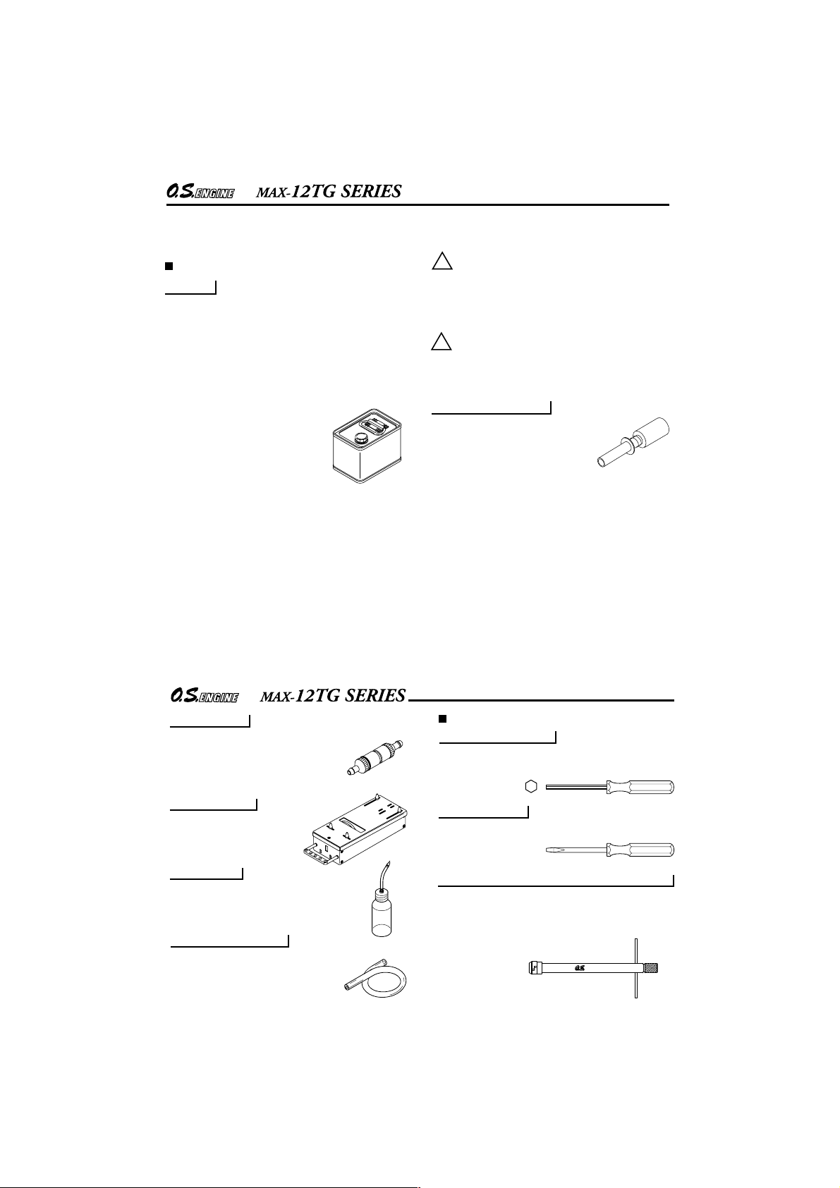
TOOLS, ACCESSORIES, etc.
The following items are necessary for operating the
engine.
Items necessary for starting
FUEL
Generally, it is suggested that the user selects a fuel
that is commercially available for model two-stroke
engines and contains 10-30% nitromethane.
As a starting point, we recommend a fuel containing
20% nitromethane, changing to a fuel containing more
nitro if necessary. When the brand of fuel is changed,
or the nitro content increased, it is advisable to repeat
the running-in procedure referred to in the RUNNINGIN paragraphs.
Please note that with high-nitro fuels,
although power may be increased for
competition purposes, glowplug
elements do not last as long and
engine life will be shorter.
REMINDER!
Model engine fuel is poisonous. Do not
allow it to come into contact with the eyes
or mouth. Always store it in a clearly
!
marked container and out of the reach of
children.
Model engine fuel is also highly flammable.
Keep it away from open flame, excessive
heat, sources of sparks, or anything else
!
which might ignite it. Do not smoke or allow
anyone else to smoke, near to it.
GLOWPLUG IGNITER
Commercialy available handy
glowplug heater in which the
glowplug battery and battery leads
are integrated.
10
FUEL FILTER
To be installed in the fuel line between
fuel tank and carburetor to prevent
dust from entering the carburetor.
STARTER BOX
For starting the engine.
It is not necessary for 12TG-X
and 12TG-PX.
FUEL PUMP
For filling the fuel tank, a simple, polyethylene "squeeze" bottle, with a suitable spout, is required.
SILICONE FUEL LINE
Heatproof silicone tubing of approx.
5mm o.d. and 2mm i.d. is required for
the connection between the fuel tank
and engine.
TOOLS
HEX SCREWDRIVER
Necessary for engine installation.
1.5mm, 2mm, 2.5mm, 3mm
SCREWDRIVER
Necessary for carburetor adjustments.
No.1, No.2, etc
LONG SOCKET WRENCH WITH PLUG GRIP
Recommended for easy removal and replacement of
the angled and recessed glowplug, the O.S.Long
Socket Wrench incorporates a special grip.
11
Page 7
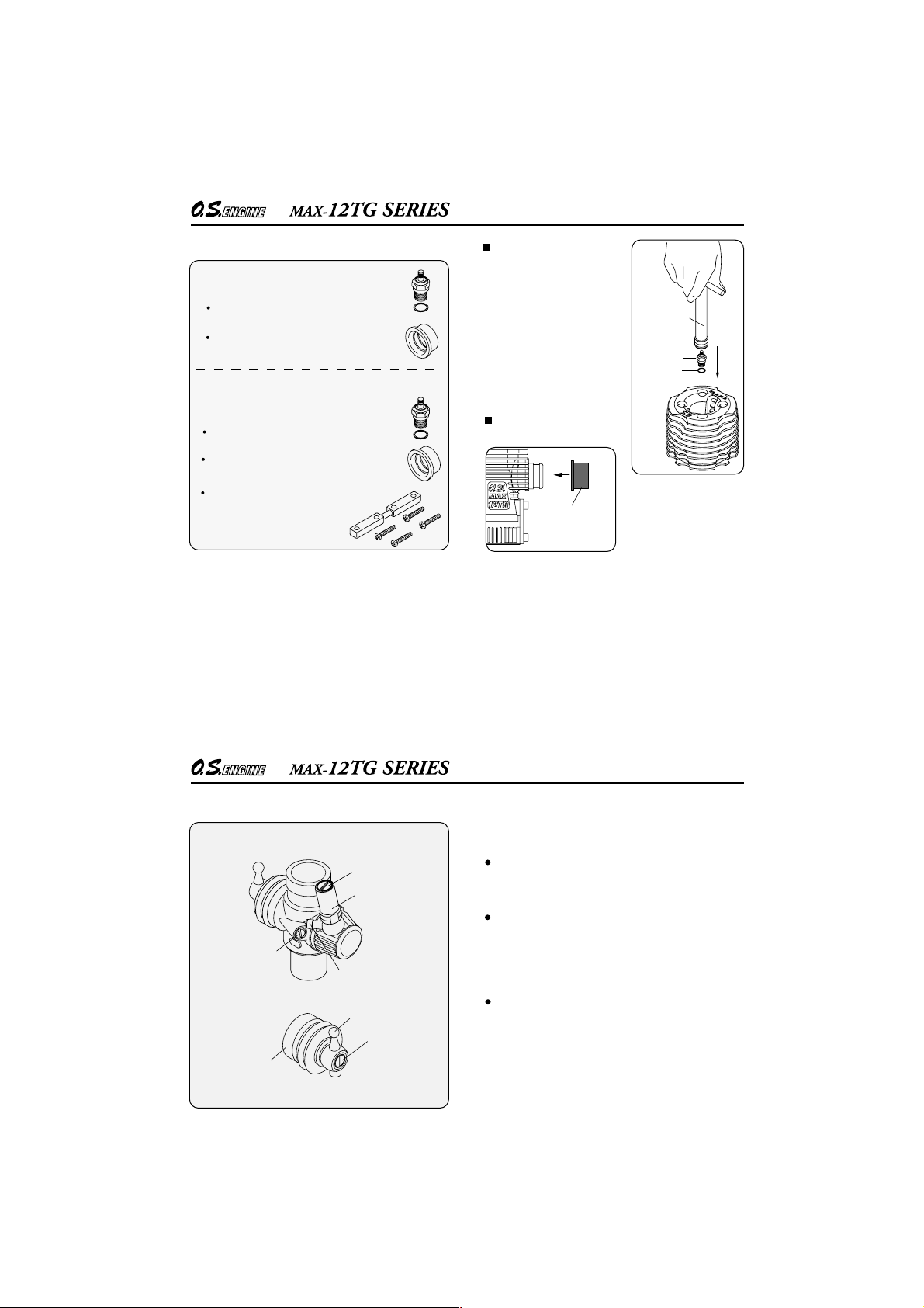
Standard accessories
MAX-
12TG,
Glow Plug No.8 1piece
Exhaust Seal Ring 1piece
MAX-
12TG-X,
Glow Plug No.8 1piece
Exhaust Seal Ring 1piece
Engine Mount Spacer 1piece
Use it when the engine interferes
with the car chassis.
MAX-
MAX-
12TG-P
12TG-PX
INSTALLING THE
GLOWPLUG
Fit washer to glowplug and
insert carefully into cylinderhead, making sure that it is
not cross-threaded before
tightening firmly.
Install the exhaust seal
ring supplied.
Exhaust
Seal Ring
12
Socket
Wrench
Glowplug
Washer
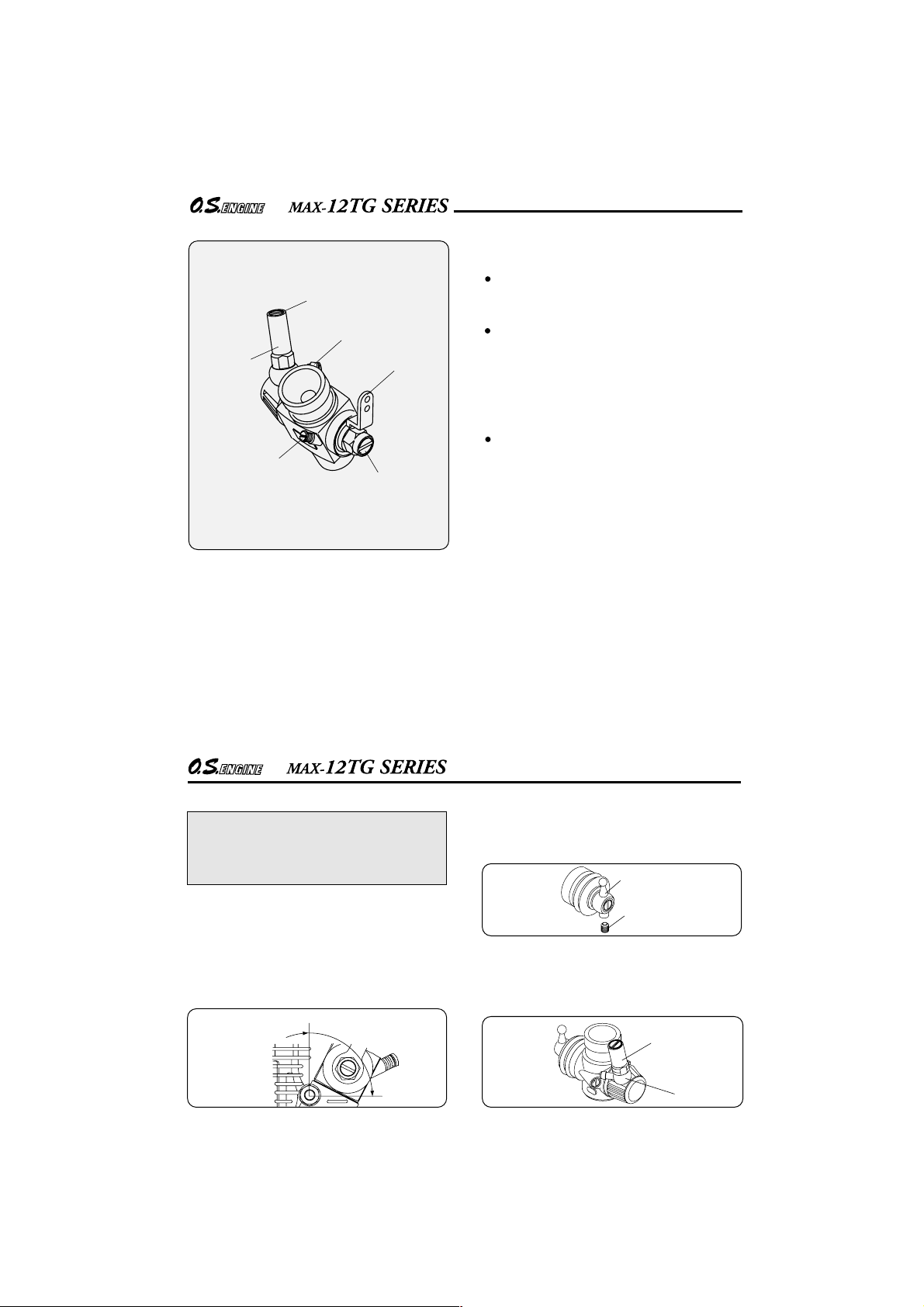
CARBURETOR CONTROLS
Carburetor Type 12D
Needle Valve
Needle Holder
Throttle Stop
Screw
Fuel Inlet
Ball Link No.5
Metering Needle
Dust Cover
Three adjustable controls are provided on this
carburetor.
The Needle-Valve(Adjusted at the factory):
For adjusting the mixture strength when the throttle
is fully open.
The Metering Needle
(Adjusted at the factory):
For adjusting the mixture strength at part-throttle
and idle speed, to obtain steady idling and smooth
acceleration to mid speed.
The Throttle Stop Screw
(Adjusted at the factory):
For setting the minimum idle speed:
NOTE: Readjustment may be necessary,
occasionally to allow for changes in fuel formula,
gear ratio or clutch engagement point.
13
Page 8
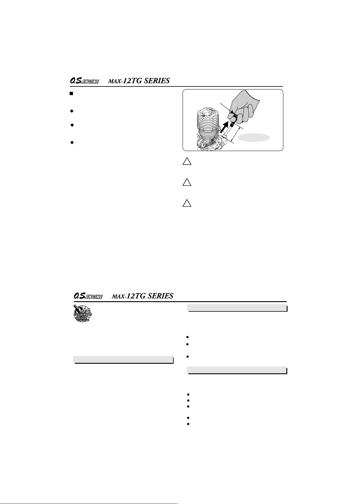
Carburetor Type 12E
Needle Holder
Throttle
Stop Screw
Needle Valve
Fuel Inlet
Throttle Lever
Mixture Control Screw
Three adjustable controls are provided on this
carburetor.
The Needle-Valve(Adjusted at the factory):
For adjusting the mixture strength when the throttle
is fully open.
The Mixture Control Screw
(Adjusted at the factory):
For adjusting the mixture strength at part-throttle
and idle speed, to obtain steady idling and smooth
acceleration to mid speed.
(It should be screwed in or out less tan one turn.)
The Throttle Stop Screw
(Adjusted at the factory):
For setting the minimum idle speed:
NOTE: Readjustment may be necessary,
occasionally to allow for changes in fuel formula,
gear ratio or clutch engagement point.
14
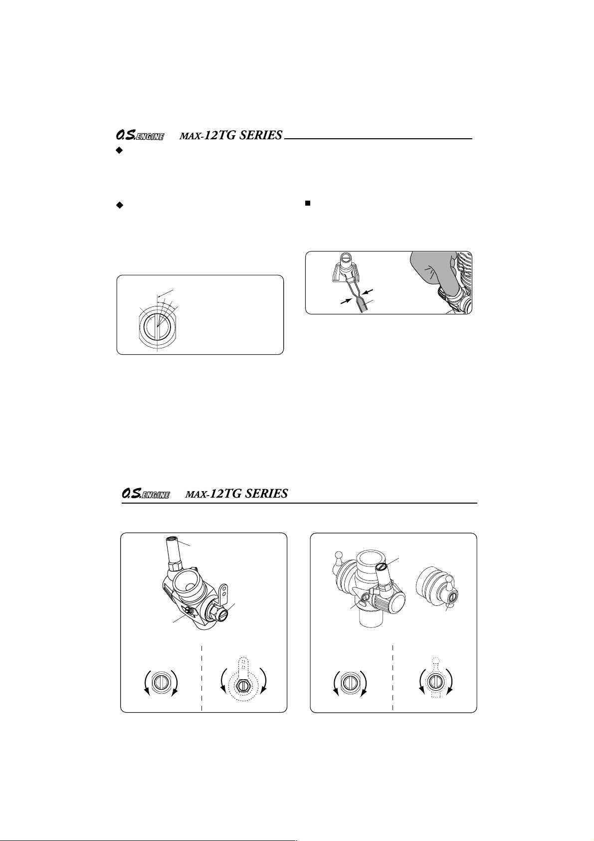
INSTALLATION OF THE CARBURETOR
NOTE
As delivered, the engine has its carburetor
lightly fit into its intake. Secure it changing its
angle according to the car chassis.
As delivered, the engine has its carburetor lightly fit into
the intake boss. Secure it as follows.
Loosen the retainer screw, rotate the carburetor to
1.
its correct position and make sure that it is
pressed well down into the intake boss,
compressing the rubber gasket, before
retightening the screw.
Rotate the retainer nut
gently until it stops.
Tighten a further 60-90˚
15
Rotate the retainer screw gently until it stops, then
2.
tighten a further 60-90˚. Do not overtighten the
screw as this will damage the carburetor body.
When changing the ball link direction, loosen the
retaining screw with a 1.5mm Hex wrench.
Ball Link
Retaining Screw
After changed the fuel inlet direction, tighten the
needle holder slowly and gently until it stops. Then,
tighten 45~60 degrees further. Do not tighten further
or the fuel inlet will be distorted, which may result in
fuel leaking.
Needle
Holder
Fuel Inlet
Page 9
NOTES CONCERNING THE RECOIL STARTER
REMINDER!
This will help prevent the cord from being damaged
by abrasion or engine heat.
Try to avoid spilling fuel over the starter unit and its
cord. Some fuels have a detrimental effect on these
parts.
The starter prevents the engine from being rotated
in the wrong direction.The unit will be damaged if you
attempt to force the flywheel in the opposite direction (i.e. clockwise when viewed from the crankshaft
end).
It is suspected that the engine is over-primed when
◆
the pulling load is too heavy to pull the starter. In this
case, refer to page 7 and TROUBLE SHOOTING
about over priming.
16
!
!
!
Starter Handle
16" 40cm MAX!
Do not attempt to disassemble the recoil
starter. If you do so, the very strong spring
inside will be suddenly ejected. This can be
very dangerous.
Do not extend the starter cord more than
40cm (16"). Do not abruptly release the
operating handle. Allow the cord to rewind
smoothly while still holding the handle.
Pull the operating handle straight out when
starting the engine, so that the cord does not
rub against the vehicle body or engine.
GLOWPLUG
Since the glowplug and fuel combination
used may have a marked effect on per-
formance and reliability, it would be
worthwhile to experiment with different plug types. An
O.S. No.8 glowplug is supplied with the engine. Recommended O.S. plugs are the No.8 and A5. Carefully
install plug finger-tight, before final tightening with the
correct size plug wrench.
The role of the glowplug
With a glowplug engine, ignition is initiated by the
application of a 1.5-volt power source. When the
battery is disconnected, the heat retained within the
combustion chamber remains sufficient to keep the
plug filament glowing, thereby continuing to keep the
engine running. Ignition timing is 'automatic' : under
reduced load, allowing higher rpm, the plug becomes
hotter and, appropriately, fires the fuel/air charge
earlier; conversely, at reduced rpm, the plug become
cooler and ignition is retarded.
Glowplug life
Particularly in the case of very high performance
engines,
glowplugs must be regarded as expendable
items. However, plug life can be extended and engine
performance maintained by careful use, i.e.:
Install a plug suitable for the engine.
Use fuel containing a moderate percentage of
nitromethane unless more is essential for racing events.
Do not run the engine too lean and do not leave the
battery connected while adjusting the needle.
When to replace the glowplug
Apart from when actually burned out, a plug may
need to be replaced because it no longer delivers its
best performance, such as when:
Filament surface has roughened and turned white.
Filament coil has become distorted.
Foreign matter has adhered to filament or plug
body has corroded.
Engine tends to cut out when idling.
Starting qualities deteriorate.
17
Page 10

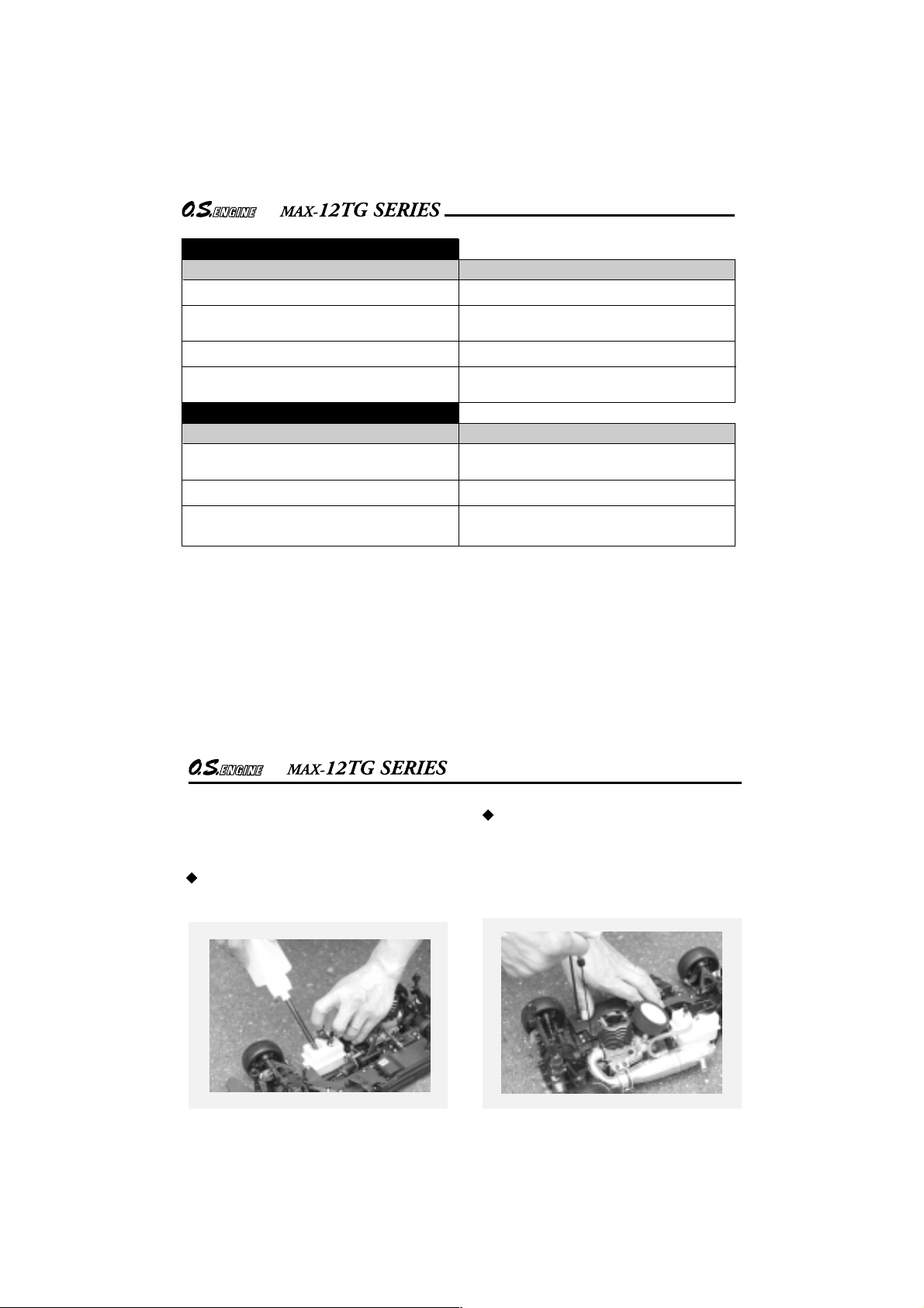
ENGINE INSTALLATION
When installing the engine on the chassis, note the
following points.
(Chamfer inside edges of bearers when the engine
mount edges interfere with the engine. Do not
chamfer the engine.)
Engine Mount
The recommended screws for securing the engine are
3mm or 4-40 steel Allen hexagon socket type.
If existing holes in the engine mount do not align
perfectly with engine mounting lugs, enlarge them
slightly with a needle-file so that screws are in
alignment with the mounting holes.
File
Make sure that the vehicle's engine mounting surfaces
are level and in the same plane. Poor installation may
cause distortion of the crankcase, bearings, etc.,
resulting in erratic running and loss of performance.
12TG-X AND 12TG-PX INSTALLATION
Avoid forcing the screws. Secure with locknuts. If
the bottom of the recoil starter housing would
otherwise touch the car chassis, install the engine
mount spacers (supplied) between the engine's
mounting lugs and the engine mount. Use the
M3x15 screws provided. With some vehicles, it
may be necessary to make minor trimming
modifications to chassis or body when installing
the engine.
If existing holes in the engine mount do not align
perfectly with engine mounting lugs, enlarge them
slightly with a needle-file so that screws are in
alignment with the mounting holes.
Chamfer inside edges of bearers.
18
Mount Spacer
Separate
Do not allow
bottom of
crankcase to
touch chassis.
Chassis
NOTE:
When spacers are supplied joined in pairs (see
sketch) separate them as shown.
Either face may be placed downwards.
JAPAN
Engine Mount
(Use the mount supplied with the car kit.)
19
Engine Mount Spacer
Page 11

STARTING THE ENGINE & RUNNING-IN ('Breaking-in)
While Operating
Please do not run on a public street, this
could cause serious accidents, personal
injuries and/or propetry damage.
Please do not run near pedestrians or small
children.
Please do not run in small or confined areas.
Please do not run where loud noises can disturb
others, such as hospitals and residential areas.
Before starting the engine, always check the
tightness of all the screws and nuts especially those of joint and movable parts such as
!
throttle arm. Missing retightening the loose
screws and nuts often causes the parts
breakage that is capable of harming you.
RUNNING-IN ('Breaking-in)
Running- in is a procedure for an engine to come
close to actual running conditions (fuel, r.p.m.,
engine temperature, etc.).
Excessively rich running and prolonged low
speed running should be avoided. Prolonged low
speed running and low temperature running may
result in the oil in the fuel being gelled and
piston/liner being stuck together.
PRESSURIZED FUEL SYSTEM
The somewhat violent changes of vehicle attitude
that occur in off-road running, combined with the
fact that, in buggy type cars, the fuel tank is often
located some distance from the carburetor, means
that fuel 'head' at the carburettor can vary and upset
running.Therefore,it is recommended that a muffler
pressurized fuel feed system be used.
Never run your vehicle without installing the air
cleaner. Dust and dirt that may otherwise be drawn
into the engine will rapidly shorten its life.
20
The following procedure is suitable when a fuel
containing up to 30% nitromethane is used.
Lay the chassis on a stand and start the engine so
that the tires are not in contact with the ground.
stand
Fill the tank completely with fuel.
Fuel Pump
Fuel Tank
Temporarily remove the glowplug to check that it
glows bright red when energized.
Element glows when
energized.
Replace the plug when the
element does not glow or is
burnt out.
Glow Plug Igniter
NOTE:
Be careful not to damage the plug threads when
holding a glowplug with pliers.
Do not hold a glowplug with fingers and use
pliers when checking the brightness. Do not
!
have your face close to the glowplug or boiled
fuel remaining in the coil will burn you.
Pliers
21
Page 12

The carburetor is set as shown below at the
factory. Start the engine as it is.
Common to 12D/12E carburetors
The needle-valve is set approx. 2.5 turns opened
from the fully closed position.
In case of the 12D carburetor
approx 0.5mm
Approx. 0.5mm open
factory setting
Turn the needle-valve clockwise until it stops. This
is the fully closed position. Do not force it to turn
further.
Open
Note
Check the throttle opening at idle before installing
an air cleaner. After the engine is started, be sure
to install an air cleaner.
Close (clockwise)
Needle Valve
Metering needle is set at basic position.
(Refer to P30.)
In case of the 12E carburetor
Approx. 1mm open
factory setting
Mixture control screw is set at basic
position. (Refer to P30.)
22
→
→
approx 1mm
Deliver fuel into the carburetor.
Swith on the transmitter and make sure that each
linkage moves correctly.
If the fuel tank is equipped with a choke button, push
the button to send the fuel to the carburetor. If not,
apply an electric starter to send the fuel to the
carburetor.
Note
If too much fuel is delivered into the engine, the
engine cannot be started due to over-priming. In
this case, refer to page 7 and TROUBLE SHOOTING
about over-priming.
23
Fuel
Fuel tank side
choke button
Fuel tank
Page 13

Now connect glowplug battery lead to heat
the plug filament and start the engine.
In case of the 12TG-X and 12TG-PX
Be sure to install an air cleaner when starting.
Pull the starter handle briskly straight out
several times to start the engine.
Do not extend the starter cord more than 40cm
(16").
Starter Handle
Glowplug
Igniter
In case of the 12TG and 12TG-P
Start the engine using a starter box, making sure
the engine rotation direction is correct (counterclockwise seen from the crankshaft end).
When the engines does not start
or stops right after started Try the followings.
Set the needle-valve approx. 2 turns open from the
fully closed position. (Do not close further.)
Set the throttle opening a little wider that the
factory set by adjusting the throttle stop screw.
air cleaner
16" 40cm MAX!
When the engine starts, first allow it to operate in
short runs at the very rich star ting settings, with
the glowplug battery still connected and the driving
wheels clear of the ground. The rich mixture will,
under these conditions, provide adequate
lubrication and cooling, indicated by profuse
smoke from the exhaust.
approx 1mm
24
Next adjust idling (low engine RPM)
Idling means …
Engine is started but the car does not move when the
throttle is positioned neutral.
Disconnect the glowplug battery If the car starts
moving (or tiers rotate), adjust the throttle stop
screw so that tiers may not rotate with steady
idling.
→
approx
1.5mm
→
Remember!
It is vitally important to set the
throttle at the correct position
before attempting to start the
engine. If the engine is allowed to
run with the throttle too far open
under "no load" conditions, it will
rapidly overheat and may be
seriously damaged.
Throttle Stop Screw
RPM Low
If the RPM are lowered too much, the engine
stops. Set the idling RPM a little higher when the
engine is new.
RPM High
Throttle Stop Screw
25
Page 14
Next, disconnect the glowplug battery and try
running the car on the track. If the engine stalls,
open the throttle fractionally, but try to keep the
engine running as rich as possible: if it stops
because of being excessively over-rich, close the
Needle-Valve 15˚ and try again.
Run the car on the track until one tank of fuel has been
consumed, then close the Needle-Valve 15˚ and run
the car for 3 to 5 full tanks of fuel. Repeat this
procedure until approx. 1 liter of fuel have been
consumed, during which time the throttle may be
opened for brief bursts of increased power. If the
engine stops at medium speeds, close the Mixture
Screw 45˚.
The position of the needle-valve
when starting the engine.
Needle
Close the needle-valve approx.
15˚ after running the vehicle for
3 to 5 full tanks of fuel.
Repeat this procedure until
approx. 1 liter of fuel have
been consumed.
Note:
In the event of any major working parts (e.g.
piston/cylinder liner assembly) being replaced or the
fuel being changed, especially to high nitro fuel, the
complete running-in should be repeated.
How to stop the engine
To stop the engine, close the throttle to idle speed
and shut it off completely with the trim lever on the
transmitter then cut off the fuel supply by pinching
the fuel delivery tube to the carburetor.
Fuel
Warning!
Do not touch rotating parts, engine and silencer
when stopping the engine as they become very hot,
and contact with them may result in a serious burn.
26
FINAL ADJUSTMENT
Needle Valve
Throttle
Stop Screw
Needle Valve
Open
More fuel
Less fuel
Mixture Control Screw
Close
Open
More fuel
Final adjustment should be carried out only after the running-in has
been completed.
Needle Valve
Mixture Control
Screw
Close
Less fuel
Throttle
Stop Screw
Needle Valve
Open
More fuel
Close
Less fuel
Metering
Needle
Metering Needle
Open
More fuel
Close
Less fuel
27
Page 15

Adjust high RPM running.
Run the vehicle (with throttle fully open) over the
longest available straight course, in order to
observe the model's speed. Next return the car to
the starting point, close the Needle-Valve 15˚ and
repeat the run, taking note of the improvement in
performance.
Continue with further runs, gradually reducing the
Needle-Valve setting and aiming to achieve the
highest straight-line speed. Remember, however,
that, if the Needle-Valve is shut down too far, the
engine will overheat and, accompanied by visibly
diminished exhaust smoke, the model will lose
speed. At this point, throttle down immediately, stop
the vehicle and reopen the Needle-Valve 15˚.
Carry out adjustment by 15
degrees at a time for both
closing and opening.
Adjust medium and low RPM running.
With the engine running, close the throttle and
allow it to idle for about five seconds, then reopen
the throttle fully. If, at this point, the engine puffs
out an excessive amount of smoke and the
vehicle does not accelerate smoothly and rapidly,
it is probable that the idle mixture is too rich.
In this case, turn the Metering Needle or Mixture
Control Screw clockwise 15˚.
If, on the other hand, the engine tends to speed
up momentarily and then cut out abruptly when
the throttle is opened, the idle mixture is too lean.
Correct this by turning the Metering Needle or
Mixture Control Screw counter-clockwise 15˚.
Carry out adjustments patiently, under actual
running conditions, until the engine responds
quickly and positively to the throttle control.
28
Warning!
Mixture adjustments (whether via the Metering
Needle, or the Needle-Valve) cannot be made
accurately under 'no-load' conditions, which, in
any case, are not advised, since such operation
carries the risk of seriously damaging the engine
through over-revving and overheating.
With the optimum mixture control position, light
smoke is visible during high speed running,and the
engine rpm increases smoothly during acceleration.
Remember that, if the engine is operated with the
fuel/air mixture slightly too lean, it will overheat and
run unevenly.
As with all engines, it is advisable to set both the
needle-valve and metering needle or Mixture
Control Screw slightly on the rich side of the best
rpm setting, as a safety measure.
If the engine runs too fast with the throttle closed,
the Mixture Control screw or metering needle
should be turned counter-clockwise to allow the
throttle opening to be reduced.
Finally, beyond the nominal break-in period, a
slight readjustment toward a leaner needle setting
may be required to maintain maximum
performance.
NOTE
The above mentioned needle opening is a guide. It
varies according to the fuel used and silencer.
Usually, when a lo wer nitro content fuel used, it will
be necessary to close the needle-valve.
Do not close the needle-valve too much or rust will
be generated and the engine will be damaged.
29
Page 16

REALIGNMENT OF METERING NEEDLE AND
MIXTURE CONTROL SCREW
In the course of making carburetor adjustments, it
is just possible that the Metering Needle and the
Mixture Control Screw may be inadvertently
screwed in or out too far and thereby moved
beyond its effective adjustment range.
The basic positions can be found by rotating the
Metering Needle until its slotted head is flush with
the ball link body.
In case of the 12D carburetor
Carburetor Body
Ball Link
Rotate the Metering
Needle until its slotted
head is flush with the
ball link body. This is the
basic position.
Metering Needle
Slide Valve
In case of the 12E carburetor
Throttle
Lever
Carburetor Body
Note:
Readjustment of the needle-valve may be
necessary to allow for changes in fuel formula,
gear ratio, clutch engagement point and muffler.
Also, needle setting may vary to atmospheric
conditions within the day. Readjust it according to
actual engine running.
Rotate the Mixture Control
Screw until its slotted
head is flush with the ball
link body.
This is the basic position.
Mixture Control Screw
30
TROUBLE SHOOTING
Symptom
Engine fails to fire.
Cause Corrective action
Fuel tank is empty.
Fuel not reaching the engine.
Glowplug element is burnt out.
Glowplug battery discharged
Clogged fuel filter
Air cleaner and silencer inside is dirty.
Fill the tank with fuel and repeat
Priming procedure.
Replace glowplug.
Recharge or replace the battery.
Clean or replace fuel filter.
Replace cleaner element and clean inside silencer.
Over priming Remove glowplug and pump out excess fuel.
Fuel tubing is disconnected.
Fuel tubing is kinked, split or has a hole.
Connect fuel tubing securely.
Check the tubing carefully and replace if necessary.
Incorrect servo linkage Connect correctly after setting servo at neutral.
Reverse rotating direction of starter box.
Recoil starter slips.
Mare sure it rotates counter clockwise seen
from crankshaft side.
Inject cleaner spray into starter cord crevis
on the body.
31
Page 17

Engine fires intermittently but does not run.
Cause
Insufficient fuel in the tank. Fill the tank with fuel.
Corrective action
Deteriorated glowplug
Clogged fuel filter
Air cleaner and silencer inside is dirty.
Engine overheated
Incorrect clutch release
Glowplug battery disconnected too soon.
Air bubbles in fuel
Replace glowplug.
Clean or replace fuel filter.
Replace cleaner element and clean inside silencer.
Wait until engine cools.
Adjust the tension of clutch spring.
Do not disconnect plug battery and wait until
r.p.m. becomes stable.
Install O rings to the tank screws to prevent
bubbles.
32
Unstable idle
Cause
Unsuitable glowplug
Unsuitable fuel
Extremely light flywheel Add suitable load.
Silencer is disconnected or has play
Not reaching expected peak r.p.m.
Cause
Insufficient warming up or running-in.
Silencer or manifold is not securely connected
or disconnected.
Fuel tubing from tank is split or broken.
Use suggested glowplug in the instructions.
Do not use extremely high nitro or
low oil content fuel.
Install silencer securely.
Set the needle only after warming up.
Complete running-in.
Replace seal ring.
Check the connections and secure them.
Replace the tubing.
33
Corrective action
Corrective action
Page 18
Poor response
Cause
Deteriorated glowplug
Incorrect carburetor settings
Incorrect setting of transmitter Exponential function.
Incorrect linkage
Poor r.p.m. drop
Cause
Throttle position open too far.
Carburetor not fully seated
Metering needle or mixture control screw
closed too far.
Corrective action
Replace glowplug.
Readjust low r.p.m. range with metering
needle or mixture control screw.
Check the transmitter setting.
Make sure the throttle servo linkage does not
bind and is connected correctly.
Corrective action
Close throttle stop screw to adequate position
to lower idle r.p.m.
Install carburetor securely.
Open the metering needle or mixture control
screw a little.
34
CARE AND MAINTENANCE
Care and maintenance after the running is very
important. Be sure to carry out the following
procedures.
Do not forget to clean the filters regularly to remove
dirt and lint that accumulate on the filter screens.
Also, clean the carburetor itself occasionally.
At the end of each operating session, drain out any
fuel that may remain in the fuel tank.
Afterwards,energize the glow-plug and try to restart
the engine, to burn off any fuel that may remain
inside the engine. Repeat this procedure until the
engine fails to fire. Do this while the engine is still
warm.
35
Page 19

Then, inject some after-run oil into the engine, and
rotate the engine with an electric starter or the
recoil starter for 4 to 5 seconds to distribute the oil
to all the working parts.
Note:
Do not inject after-run oil into the carburetor as
this may cause the O-rings inside the carburetor
to deteriorate. These procedures will reduce the
risks of starting difficulties or corrosion after a
period of storage.
Finally, when cleaning the exterior of the
engine, use methanol. Do not use gasoline
or any solvent that might damage the silicone
fuel tubing.
36
The minute particles of foreign matter, that are present
in any fuel may, by accumulating and partially
obstructing fuel flow, cause engine performance to
become erratic and unreliable.
O.S. 'Super-Filters' (large and small) are available, as
optional extras, to deal with this problem.
One of these filters installed to the pickup tube inside
your refueling container, will prevent the entry of
foreign material into the fuel tank. It is also
recommended that a good in-line filter be installed
between the tank and carburetor.
Dirt and dust may lodge in marked places.
CHECKING THE ENGINE
If the engine suffers a loss of performance after a
long period of running it may be due to the wearing of
parts. It is suggested that the worn parts be replaced
when the following symptoms are detected.
Engine sound changes and easily overheats.
Power has dropped considerably.
Idle is unstable and/or engine tends to stop
at idle.
In most cases, ball bearings, cylinder & piston assembly ,
connecting rod and/or crankcase have become worn
out or abnormal. Check the parts carefully and replace
them if necessary.
37
Page 20

38
C.M3x16
1
7
MAX-
12TG ENGINE EXPLODED VIEW
No.
Code No.
21414000
1
21413000
2
21536000
3
21817000
4
21415000
16
2
4
3
5
6
13
12
11
14
C.M2.6x7
15
5
21428000
6
25381701
7
20810007
8
21458000
9
22631020
10
21411000
11
21931000
12
39
13
14
15
16
21412020
21411400
21417000
23763000
71608001
21427200
The specifications are subject to alteration for improvement without notice.
MAX-
12TG ENGINE PARTS LIST
Description
Heatsink Head
Cylinder & Piston Assembly
Piston Pin
Piston Pin Retainer (2pcs.)
Connecting Rod
Carburetor Complete (Type 12E)
Carburetor Retainer Assembly
Propeller Nut
Drive Hub
Crankshaft Ball Bearing (Front)
Crankcase
Crankshaft Ball Bearing (Rear)
Crankshaft
Gasket Set
Cover Plate
Screw Set
Glow Plug No.8
Exhaust Seal Ring
10
9
8
Type of screw
C...Cap Screw M...Oval Fillister-Head Screw
F...Flat Head Screw N...Round Head Screw S...Set Screw
Page 21

MAX-
12TG-X ENGINE EXPLODED VIEW
C.M3x16
1
40
8
Type of screw
C...Cap Screw M...Oval Fillister-Head Screw
F...Flat Head Screw N...Round Head Screw S...Set Screw
4
3
5
6
7
11
10
9
15
12
2
16
M.+M2.6x7
MAX-
12TG-X ENGINE PARTS LIST
No.
Code No.
21414000
1
21413000
2
21536000
3
21817000
4
21415000
5
21428000
6
25381701
7
20810007
8
21458000
9
22631020
41
10
11
12
13
14
15
16
17
17-1
17-2
18
21411000
21931000
21412030
21411400
21922000
21901800
73008000
73008100
73008200
21923000
14
13
18
N.+M2.6x6
71608001
21427200
72404000
17-2
17-1
17
The specifications are subject to alteration for improvement without notice.
Heatsink Head
Cylinder & Piston Assembly
Piston Pin
Piston Pin Retainer (2pcs.)
Connecting Rod
Carburetor Complete (Type 12E)
Carburetor Retainer Assembly
Propeller Nut
Drive Hub
Crankshaft Ball Bearing (Front)
Crankcase
Crankshaft Ball Bearing (Rear)
Crankshaft
Gasket Set
Starting Shaft
Rear Adaptor
No.N1 Recoil Starter Assembly
No.N1 Recoil Starter Body
No.N1 One-way Clutch
Screw Set
Glow Plug No.8
Exhaust Seal Ring
Engine Mount Spacer
Description
Page 22

C.M3x16
MAX-
12TG-P ENGINE EXPLODED VIEW
MAX-
12TG-P ENGINE PARTS LIST
1
42
4
3
5
6
7
9
8
Type of screw
C...Cap Screw M...Oval Fillister-Head Screw
F...Flat Head Screw N...Round Head Screw S...Set Screw
No.
Code No.
21414000
1
21413000
2
21536000
3
21817000
4
21415000
43
5
6
7
8
9
10
11
12
13
14
21418000
25381701
22631020
21411000
21931000
21412000
21411400
21417000
23763000
14
2
12
C.M2.6x7
71608001
21427200
The specifications are subject to alteration for improvement without notice.
13
11
10
Heatsink Head
Cylinder & Piston Assembly
Piston Pin
Piston Pin Retainer (2pcs.)
Connecting Rod
Carburetor Complete (Type 12D)
Carburetor Retainer Assembly
Crankshaft Ball Bearing (Front)
Crankcase
Crankshaft Ball Bearing (Rear)
Crankshaft
Gasket Set
Cover Plate
Screw Set
Glow Plug No.8
Exhaust Seal Ring
Description
Page 23

44
C.M3x16
1
7
MAX-
12TG-PX ENGINE EXPLODED VIEW
No.
Code No.
21414000
1
21413000
2
21536000
3
21817000
4
21415000
5
21418000
6
25381701
7
22631020
8
21411000
9
21931000
2
4
3
5
6
11
M.+M2.6x7
10
12
16
N.+M2.6x6
10
21412010
11
21411400
12
45
13
14
15
15-1
15-2
16
21922000
21901800
73008000
73008100
73008200
21923000
71608001
21427200
72404000
The specifications are subject to alteration for improvement without notice.
MAX-
12TG-PX ENGINE PARTS LIST
Heatsink Head
Cylinder & Piston Assembly
Piston Pin
Piston Pin Retainer (2pcs.)
Connecting Rod
Carburetor Complete (Type 12D)
Carburetor Retainer Assembly
Crankshaft Ball Bearing (Front)
Crankcase
Crankshaft Ball Bearing (Rear)
Crankshaft
Gasket Set
Starting Shaft
Rear Adaptor
No.N1 Recoil Starter Assembly
No.N1 Recoil Starter Body
No.N1 One-way Clutch
Screw Set
Glow Plug No.8
Exhaust Seal Ring
Engine Mount Spacer
Description
9
8
Type of screw
C...Cap Screw M...Oval Fillister-Head Screw
F...Flat Head Screw N...Round Head Screw S...Set Screw
14
13
15-2
15-1
15
Page 24

1-1
1
1-2
2
Type of screw
C...Cap Screw M...Oval Fillister-Head Screw
F...Flat Head Screw N...Round Head Screw S...Set Screw
12E CARBURETOR EXPLODED VIEW
3
4
5
6
7
10
46
9
9-1
8
12E CARBURETOR PART LIST
No.
Code No.
1
21285901
1-1
27881820
1-2
21881950
2
22681310
3
21428100
4
22481506
5
21428200
6
21283210
7
22681419
8
21481420
9
21982630
9-1
27881820
10
22615000
The specifications are subject to alteration for improvement without notice.
Needle Valve Assembly
"O" Ring (2pcs.)
No.14 Universal Nipple Assembly
Throttle Stop Screw
Carburetor Body
Rotor Spring
Carburetor Rotor
Dust Cover
Throttle Lever
Throttle Lever Fixing Nut
Mixture Control Screw
"O" Ring (2pcs.)
Carburetor Rubber Gasket
Description
47
Page 25

12D CARBURETOR EXPLODED VIEW
1-1
1
1-2
Type of screw
C...Cap Screw M...Oval Fillister-Head Screw
F...Flat Head Screw N...Round Head Screw S...Set Screw
2
2-1
3
4
8
5
5-1
6
7
S.M3x3
48
12D CARBURETOR PART LIST
No.
Code No.
1
21982970
1-1
27881820
1-2
21881950
2
21982620
2-1
22781800
3
21418100
4
21982200
5
21538500
5-1
22781800
6
21982520
7
23818430
8
22615000
The specifications are subject to alteration for improvement without notice.
Needle Valve Assembly
"O" Ring (2pcs.)
No.14 Universal Nipple Assembly
Throttle Stop Screw
"O" Ring (2pcs.)
Carburetor Body
Slide Valve
Metering Needle Assembly
"O" Ring (2pcs.)
Dust Cover
Ball Link No.5
Carburetor Rubber Gasket
Description
49
Page 26

O.S. Glow Plug
No.8
(71608001)
A5
(71605100)
Tuned Silencer
Spring connect type
T-1040SC L52 Tuned
Silencer Assembly
(72106310)
Left side exhaust
Tuned Silencer Body
(72106311)
Exhaust Seal Ring (2pcs.)
(22826140)
Joint Spring (3pcs.)
(72106042)
Exhaust Manifold Assembly
(72106420)
M1001
Left side exhaust,
Joint tube type
Manifold Spring
(72106172)
(72103180)
M1010
Right side exhaust,
Joint tube type
Manifold Spring
(72106172)
T-1040SC R52 Tuned
Silencer Assembly
(72106320)
Right side exhaust
Tuned Silencer Body
(72106321)
Exhaust Seal Ring (2pcs.)
(22826140)
Joint Spring (3pcs.)
(72106042)
M1001SC
Left side exhaust,
Spring connect type
M1011SC
Right side exhaust,
Spring connect type
50
O.S. GENUINE PARTS & ACCESSORIES
(72106400)
Manifold Spring
(72106172)
(72106410)
Manifold Spring
(72106172)
T-1040SC L60 Tuned
Silencer Assembly
(72106360)
Left side exhaust
Tuned Silencer Body
(72106361)
Exhaust Seal Ring (2pcs.)
(22826140)
Joint Spring (3pcs.)
(72106042)
(72106450)
M1003
Left side exhaust,
Joint tube type
Manifold Spring
(72106172)
M1003SC
Left side exhaust,
Spring connect type
(72106460)
Manifold Spring
(72106172)
T-1040SC R60 Tuned
Silencer Assembly
(72106370)
Right side exhaust
Tuned Silencer Body
(72106371)
Exhaust Seal Ring (2pcs.)
(22826140)
Joint Spring (3pcs.)
(72106042)
Joint tube type
T-1040 L52
(72103051)
T-1040 R52
(72103056)
T-1040 L60
(72106340)
T-1040 R60
(72106350)
Left side exhaust
Right side exhaust
Left side exhaust
Right side exhaust
T-1040SC L60 Complete Set
(For VoneS )
T-1040SC L60
Tuned Silencer Assembly
(72106360)
M1003SC Exhaust
Manifold Assembly
(72106460)
Exhaust Seal Ring
(21427200)
(72106540)
(2pcs.)
O.S. GENUINE PARTS & ACCESSORIES
T-1040SC L52 Complete Set
(72106500)
T-1040SC L52
Tuned Silencer Assembly
(72106310)
M1001SC Exhaust
Manifold Assembly
(72106400)
Exhaust Seal Ring
(21427200)
T-1040SC L60 Complete Set
(72106520)
T-1040SC L60
Tuned Silencer Assembly
(72106360)
M1001SC Exhaust
Manifold Assembly
(72106400)
Exhaust Seal Ring
(21427200)
(2pcs.)
(2pcs.)
51
T-1040SC R52 Complete Set
(72106510)
T-1040SC R52
Tuned Silencer Assembly
(72106320)
M1011SC Exhaust
Manifold Assembly
(72106410)
Exhaust Seal Ring
(21427200)
T-1040SC R60 Complete Set
(72106530)
(2pcs.)
T-1040SC R60
Tuned Silencer Assembly
(72106370)
M1011SC Exhaust
Manifold Assembly
(72106410)
Exhaust Seal Ring
(21427200)
(2pcs.)
Page 27

O.S. GENUINE PARTS & ACCESSORIES
Super Air Cleaner 202
(72412000)
On-road T ype
202 Cleaner Body
(72412100)
202 Filter Element (4pcs.)
(72412200)
Exhaust Seal Ring
(21427200)
(2pcs.)
SUPER AIR CLEANER 203
(72413000)
Dust Cap Set
(5pcs.)
3mm
(73300305)
(3pcs.)
16mm
(73301612)
Off-road T ype
Engine Mount Spacer
(72404000)
203 Filter Element (4pcs.)
(72413200)
Cap Screw Set
M2.6x7
The specifications are subject to alteration for improvement without notice.
(10pcs.)
(79871020)
Super Joint Tube 15
(72103310)
Long Socket Wrench
With Plug Grip
52
SPECIFICATIONS
Displacement
■
Bore
■
Stroke
■
Practical R.P.M.
■
Power output
■
Weight
■
2.1 cc (0.128 cu.in.)
13.8 mm (0.543 in.)
14.0 mm (0.551 in.)
5,000-30,000 r.p.m.
0.7 ps / 28,000 r.p.m.
212.8 g (7.5 oz.)
25.4
39
12TG THREE VIEW DRAWING
31.4
4- 3.3
11
77
M5x0.8
JAPAN
Dimensions (mm)
53
13
40.9
15.1
Page 28

SPECIFICATIONS
Displacement
■
Bore
■
Stroke
■
Practical R.P.M.
■
Power output
■
Weight
■
2.1 cc (0.128 cu.in.)
13.8 mm (0.543 in.)
14.0 mm (0.551 in.)
5,000-30,000 r.p.m.
0.7 ps / 28,000 r.p.m.
251.4 g (8.87 oz.)
12TG-X THREE VIEW DRAWING
31.4
4- 3.3
11
77
M5x0.8
JAPAN
SPECIFICATIONS
Displacement
■
■
Bore
■
Stroke
■
Practical R.P.M.
■
Power output
■
Weight
25.4
39
2.1 cc (0.128 cu.in.)
13.8 mm (0.543 in.)
14.0 mm (0.551 in.)
5,000-30,000 r.p.m.
0.7 ps / 28,000 r.p.m.
211.3 g (7.45 oz.)
54
13
40.9
34.6
12TG-P THREE VIEW DRAWING
4- 3.3
11
Dimensions (mm)
31.4
25.4
39
77
JAPAN
UNEF1/4-28
29.5
JAPAN
34.9
15.1
Dimensions (mm)
55
Page 29

SPECIFICATIONS
Displacement
■
Bore
■
Stroke
■
Practical R.P.M.
■
Power output
■
Weight
■
2.1 cc (0.128 cu.in.)
13.8 mm (0.543 in.)
14.0 mm (0.551 in.)
5,000-30,000 r.p.m.
0.7 ps / 28,000 r.p.m.
250 g (8.82 oz.)
12TG-PX THREE VIEW DRAWING
31.4
4- 3.3
11
77
25.4
JAPAN
39
UNEF1/4-28
29.5
JAPAN
34.9
34.6
Dimensions (mm)
56
C
Copyright 2006 by O.S.Engines Mfg. Co., Ltd. All rights reserved. Printed in Japan.
6-15 3-Chome Imagawa Higashisumiyoshi-ku
Osaka 546-0003, Japan
TEL. (06)6702-0225
FAX. (06)6704-2722
URL : http://www.os-engines.co.jp
60091800 060600
 Loading...