

O.S. engine MAX-61LX, MAX-61LX-HRING Owner's Manual
It is of vital importance, before attempting to
operate your engine, to read the general
'SAFETY INSTRUCTIONS AND WARNINGS'
section on pages 2-5 of this booklet and to strictly
adhere to the advice contained therein.
●
Also, please study the entire contents of this
instruction manual, so as to familiarize yourself
with the controls and other features of the
engine.
Keep these instructions in a safe place so that
you may readily refer to them whenever
necessary.
It is suggested that any instructions supplied
with the model, radio control equipment, etc.,
are accessible for checking at the same time.
●
●
MAX-61LX-HRING SERIES

SAFETY INSTRUCTIONS AND WARNINGS
ABOUT YOUR O.S. ENGINE
INTRODUCTION
BASIC ENGINE PARTS,
INSTALLATION
BEFORE STARTING
FACTS ABOUT GLOW PLUGS
FUEL
CARBURETTOR CONTROLS
STARTING
RUNNING-IN, SETTING UP,
ST ARTING AND ADJUSTMENT
SUBSEQUENT READJUSTMENTS
CARBURETTOR CLEANLINESS
ADJUSTING CHART
INSTALLATION OF THROTTLE SERVO
CARE AND MAINTENANCE
ENGINE EXPLODED VIEW &
PARTS LIST
CARBURETTOR EXPLODED
VIEW & PARTS LIST
THREE VIEW DRAWING
O.S. GENUINE PARTS & ACCESSORIES
CONTENTS
2~5
6
7
~
8
8
~
10
10
~
11
12
13
~
14
18
18
20
22~23
24
25
15
~
17
19
26
21
1
Remember that your engine is not a "toy", but a highly efficient internalcombustion machine whose power is capable of harming you, or others, if it is
misused.
As owner, you, alone, are responsible for the safe operation of your engine, so act
with discretion and care at all times.
If at some future date, your O.S. engine is acquired by another person, we would
respectfully request that these instructions are also passed on to its new owner.
SAFETY INSTRUCTIONS AND WARNINGS ABOUT YOUR O.S. ENGINE
The advice which follows is grouped under two headings according to the
degree of damage or danger which might arise through misuse or neglect.
WARNINGS
NOTES
These cover events which
might involve serious (in
extreme circumstances, even
fatal) injury.
These cover the many other
possibilities, generally less obvious
sources of danger, but which, under
certain circumstances, may also
cause damage or injury.
2
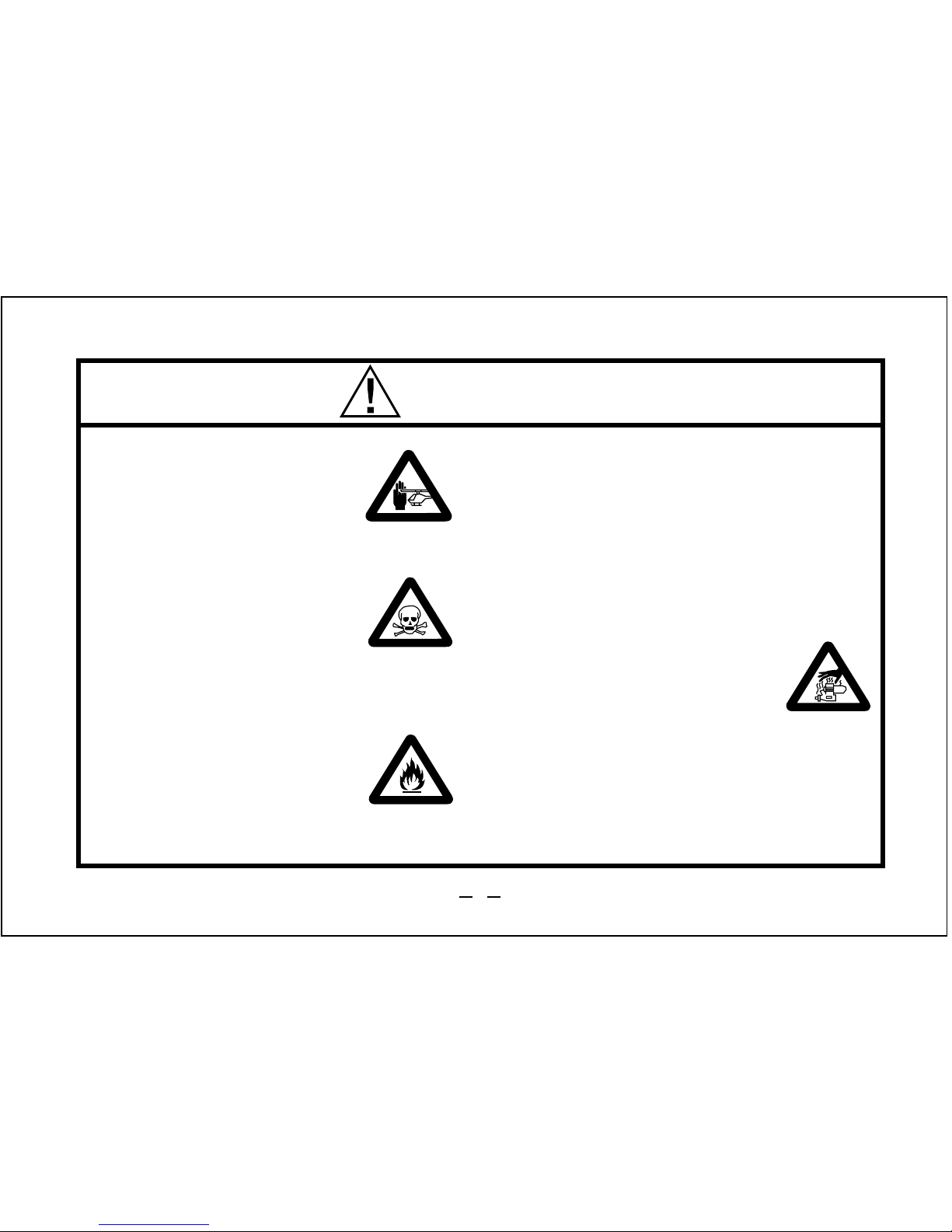
WARNINGS
•
•
•
•
•
Never touch, or allow any
object to come into contact
with, the rotating parts.
Model engine fuel is poisonous. Do not allow it to come
into contact with the eyes or
mouth. Always store it in a
clearly marked container and
out of the reach of children.
Model engine fuel is also
highly flammable. Keep it
away from open flame,
excessive heat, sources of
sparks, or anything else which
might ignite it. Do not smoke
or allow anyone else to smoke,
near to it.
Model engines generate
considerable heat. Do not
touch any part of your
engine until it has cooled.
Contact with the muffler
(silencer), cylinder head or
exhaust header pipe, in
particular, may result in a
serious burn.
Never operate your engine in an enclosed space. Model engines, like automobile engines, exhaust deadly carbonmonoxide. Run your engine only in an
open area.
3

NOTES
•
•
•
•
•
These engine were designed for model
helicopters. Do not attempt to use it for any
other purpose.
Mount the engine in your model securely, following the manufacturers' recommendations,
using appropriate screws and locknuts.
Install an effective silencer (muffler). Frequent
close exposure to a noisy exhaust (especially
in the case of the more powerful high-speed
engines) may eventually impair your hearing
and such noise is also likely to cause
annoyance to others over a wide area.
Check the linkage to the throttle arm before
each flight.
Avoid sudden high r.p.m. immediately after the
engine is started, as the clutch will engage and
you may be struck by the rotor.
•
•
After starting the engine, carry out any needlevalve readjustments after stopping the rotor by
closing the throttle to the lowest r.p.m..
Stop the engine before attempting to make
other adjustments to the carburetor.
Use an electric starter. The wearing of safety
glasses is also strongly recommended.
Press the rotor head down securely.
Take care that the glow plug clip or battery
leads do not come into contact with rotating
parts.
Adjust the throttle linkage so that the engine
stops when the throttle stick and trim lever on
the transmitter are fully retarded. Alternatively,
the engine may be stopped by cutting off the
fuel supply. Never try to stop the engine
physically.
•
•
4

NOTES
•
•
•
Take care that loose clothing (ties, shirt sleeves,
scarves etc.) do not come into contact with the
rotor. Do not carry loose objects (such as pencils, screwdrivers, etc.) in a shirt pocket from
where they could fall through the rotor disc.
For their safety, keep all onlookers (especially
small children) well back (at least 20 feet or 6
metres) when preparing your model for flight. If
you have to carry the model to the take-off point
with the engine running, be especially cautious.
Hold the rotor securely and keep well clear of
spectators.
Warning! lmmediately after a glowplug-ignition
engine has been run and is still warm,
conditions sometimes exist whereby it is just
possible for the engine to restart when turned
over WITHOUT the glowplug battery being
reconnected. Remember this if you wish to
avoid the risk of accidents.
5

Because of this initial tightness, a
standard electric starter may have
difficulty in rotating the engine when
cold, before it has been adequately
run-in. In this case, use a high-torque
type starter.
DO NOT, however, confuse tightness
with the symptoms of hydraulic lock
caused by an excess of fuel within the
cylinder - often the result of overpriming.
Attempting to force the engine to turn
over in this condition may cause
internal damage. Instead, remove the
glowplug, invert the engine and eject
surplus fuel from the combustionchamber.
Note:
The ringed-piston MAX-61LX-H, MAX61LX-HG(R) and MAX-61LX-HGL are highperformance, high-quality engines that
have been developed specifically for
radio-controlled 60 class helicopters.
They are ideal for scale and sport flyers,
for newcomers to 60 class helicopters and
for contest flyers' first-line or reserve
models.
These motors are produced by the world's
oldest and largest model engine design
and manufacturing company, a company
that has built more helicopter engines
than any other manufacturer worldwide.
INTRODUCTION
6
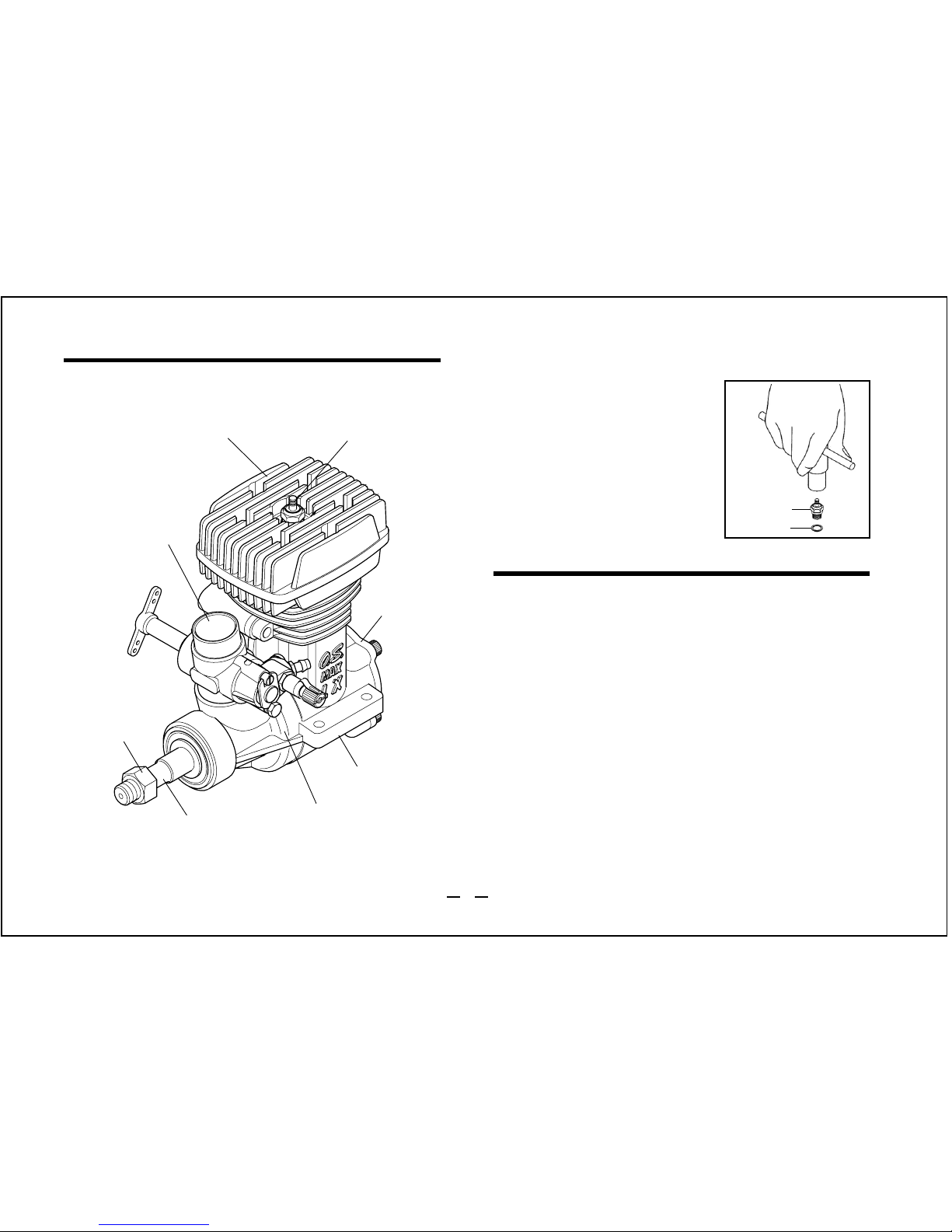
BASIC ENGINE PARTS
Heatsink Head
Carburettor
Crankshaft
Propeller nut
Crankcase
Glowplug
Mounting Lugs
INSTALLING THE GLOWPLUG
Install the washer on the
glowplug and screw
carefully into cylinderhead, making sure that it
is not cross-threaded
before tightening firmly.
Glow plug
Washer
INSTALLATION OF THE ENGINE
The under-surfaces of all O.S. engine beam
mounting lugs are precision machined flat and
exactyly parallel to the engine's horizontal axis. It is
essential that the engine mounts in the model are
also accurately made and aligned. If they are not,
they will cause stress and distortion within the engine
itself, probably resulting in loss of performance and
internal damage.
The recommended screws for securing the engine to
the engine mounts in the model are 4mm or 6-32 NC
steel Allen type. It is also advisable to use lock
washers or LOCTITE to prevent nuts from loosening.
Cover Plate
7
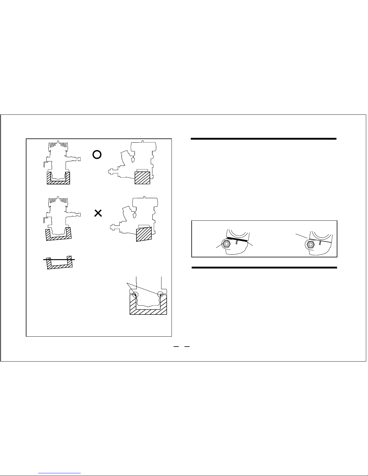
Front view
CORRECT
Side view
Top surfaces are in the same plane.
Re-align the surfaces as necessary
INCORRECT
Top surfaces are not
in the same plane.
Top surfaces are not in the
same plane.
Engine does not rest firmly.
BEFORE STARTING
Tools, accessories, etc.
The following items are necessary for operating the
engine.
1 Fuel
Model glowplug engine fuel of good quality, preferably
containing a small percentage of nitromethane.
Make sure that only the under-surfaces
of the engine’s mounting lugs are in
contact with the engine mount.
If the crankcase body touches the
mount, chamfer the edges of the mount.
As delivered, the engine has its carburetor lightly
fitted into its intake boss. Secure it as follows.
INSTALLATION OF THE CARBURETOR
Retainer
nut
Carburetor Rubber
Gasket
0.2mm gap
Loosen the retainer nut, rotate the carburetor to its
correct position and press it well down into the
intake boss, compressing the rubber gasket as
shown in the sketch, before re-tightening screw.
Rotate the retainer nut gently until it stops, then
tighten a further 90-120 degrees.
1.
2.
8
 Loading...