


It is of vital importance, before attempting to
operate your engine, to read the general
'SAFETY INSTRUCTIONS AND WARNINGS'
section on pages 2-4 of this booklet and to
strictly adhere to the advice contained therein.
Also, please study the entire contents of this
instruction manual, so as to familiarize yourself
with the controls and other features of the engine.
Keep these instructions in a safe place so that
you may readily refer to them whenever
necessary.
It is suggested that any instructions supplied with
the aircraft, radio control equipment, etc., are
accessible for checking at the same time.
1
2-4
5
6
7-8
8-9
9
10
11-13
13
14
15-16
16-17
17
18
19
20-21
22
23
24
CONTENTS
SAFETY INSTRUCTIONS AND
WARNINGS ABOUT YOUR O.S. ENGINE
INTRODUCTION, BASIC ENGINE PARTS
INSTALLATION
FUEL TANK, PIPING
GLOWPLUG
FUEL
PROPELLERS
TUNED SILENCER
CARBURETOR CONTROLS
STARTING
RUNNING-IN (Breaking-in)
MIXTURE CONTROL ADJUSTMENT
PD-06 FUEL PUMP -WARNING!
ENGINE CARE AND MAINTENANCE
CARBURETOR EXPLODED VIEWS
& PARTS LISTS
ENGINE EXPLODED VIEWS &
ENGINE PARTS LISTS
GENUINE O.S. PARTS & ACCESSORIES
ENGINE THREE VIEW DRAWINGS
MEMO

2
Remember that your engine is not a " toy ", but a
highly efficient internal-combustion machine whose
power is capable of harming you, or others, if it is
misused or abused. As owner, you, alone, are
responsible for the safe operation of your engine, so
act with discretion and care at all times.
If at some future date, your O.S. engine is acquired by
another person, we would respectfully request that
these instructions are also passed on to its new
owner.
WARNINGS
These cover events which might involve serious ( in
extreme circumstances, even fatal ) injury.
NOTES
These cover the many other possibilities, generally less
obvious sources of danger, but which, under certain
circumstances, may also cause damage or injury.
SAFETY INSTRUCTIONS AND
WARNINGS ABOUT YOUR
O.S. ENGINE
The advice which follows is grouped under two
headings according to the degree of damage or
danger which might arise through misuse or neglect.
WARNINGS
Never touch, or allow any object to come into
contact with, the rotating propeller and do not
crouch over the engine when it is running.
A weakened or loose propeller may disintegrate or be
thrown off and, since propeller tip speeds with powerful
engines may exceed 600 feet(180 meters) per second, it
will be understood that such a failure could result in
serious injury, (see 'NOTES' section relating to propeller
safety).
Model engine fuel is poisonous. Do not allow it
to come into contact with the eyes or mouth.
Always store it in a clearly marked container
and out of the reach of children.
Model engine fuel is also highly flammable.
Keep it away from open flame, excessive heat,
sources of sparks, or anything else which
might ignite it. Do not smoke or allow anyone
else to smoke, near to it.
Never operate your engine in an enclosed space. Model
engines, like automobile engines, exhaust deadly carbonmonoxide. Run your engine only in an open area.
Model engines generate considerable heat.
Do not touch any part of your engine until it
has cooled. Contact with the muffler(silencer),
cylinder head or exhaust header pipe, in
particular, may result in a serious burn.
3
NOTES
This engine was designed for model aircraft. Do not attempt to use it for any other purpose.
Mount the engine in your model securely, following the manufacturers' recommendations, using appropriate screws and
locknuts.
Be sure to use the silencer (muffler) supplied with the engine. Frequent exposure to an open exhaust may eventually impair
your hearing.
Such noise is also likely to cause annoyance to others over a wide area.
Fit a top-quality propeller of the diameter and pitch specified for the engine and aircraft. Locate the propeller on the shaft
so that the curved face of the blades faces forward-i.e. in the direction of flight. Firmly tighten the propeller nut, using the
correct size wrench.
Always check the tightness of the propeller nut and retighten it, if necessary, before restarting the engine, particularly in
the case of four-stroke-cycle engines. A safety locknut assembly is provided. Always use it. This will prevent the propeller
from flying off in the event of a "backfire", even if it loosens.
If you install a spinner, make sure that it is a precision made product and that the slots for the propeller blades do not cut
into the blade roots and weaken them.
Discard any propeller which has become split, cracked, nicked or otherwise rendered unsafe. Never attempt to repair such
a propeller: destroy it. Do not modify a propeller in any way, unless you are highly experienced in tuning propellers for
specialized competition work such as pylon-racing.
Use an electric starter for this engine. The wearing of safety glasses is also strongly recommended.
4
NOTES
Take care that the glow plug clip or battery leads do not come into contact with the propeller.
Also check the linkage to the throttle arm. A disconnected linkage could also foul the propeller.
After starting the engine, carry out any needle-valve readjustments from a safe position behind the rotating propeller.
Stop the engine before attempting to make other adjustments to the carburettor.
Adjust the throttle linkage so that the engine stops when the throttle stick and trim lever on the transmitter are fully
retarded. Alternatively, the engine may be stopped by cutting off the fuel supply. Never try to stop the engine physically.
Take care that loose clothing (ties, shirt sleeves, scarves, etc.) do not come into contact with the propeller.
Do not carry loose objects (such as pencils, screwdrivers, etc.) in a shirt pocket from where they could fall through the
propeller arc.
Do not start your engine in an area containing loose gravel or sand. The propeller may throw such material in your face
and eyes and cause injury.
For their safety, keep all onlookers (especially small children) well back (at least 20 feet or 6 meters) when preparing your
model for flight. If you have to carry the model to the take-off point with the engine running, be especially cautious.
Keep the propeller pointed away from you and walk well clear of spectators.
Warning! Immediately after a glowplug-ignition engine has been run and is still warm, conditions sometimes exist
whereby it is just possible for the engine to abruptly restart if the propeller is casually flipped over compression
WITHOUT the glowplug battery being reconnected.
Remember this if you wish to avoid the risk of a painfully rapped knuckle!
5
The entirely new 23cc MAX-140RX has been designed
expressly for FAI aerobatic competition under the latest
F3A regulations which permit two-stroke engines to have
a much larger displacement than the 10cc limit imposed
hitherto. The 140RX continues the long established O.S.
MAX contest engine tradition of unsurpassed quality of
construction, durability, reliability, compactness, high
specific output and high power-to-weight ratio. The 140RX
takes into account the need to achieve greater durability
through improved resistance to the crankshaft and main
ball-bearing corrosion that may occur under the severe
operating conditions of highly competitive FAI turnaround
aerobatic flying. The 140RX is equipped with a new O.S.
Type 70A carburetor and O.S. Type PD-06 diaphragm fuel
pump, specially developed for this engine. This fuel
system provides stable power and consistent throttle
response at all times, irrespective of fuel tank location or
aircraft attitude. The 140RX is an engine for experts and, in
order to achieve the levels of performance of which it is
capable, it is vitally important to correctly match the
propeller and tuned exhaust system to the engine's
operating characteristics. If propeller size and/or silencer
length are incorrect, the engine may actually produce
lower performance than that of a conventional standard
engine. Therefore, please read through all the following
instructions carefully.
INTRODUCTION
Needle-valve sensitivity
If the needle-valve adjustment is found to be too critical
when using the standard needle fitted to the engine, this
may be replaced with the optional, less sharply tapered
needle (Code No.22681980), to de-sensitize adjustment.
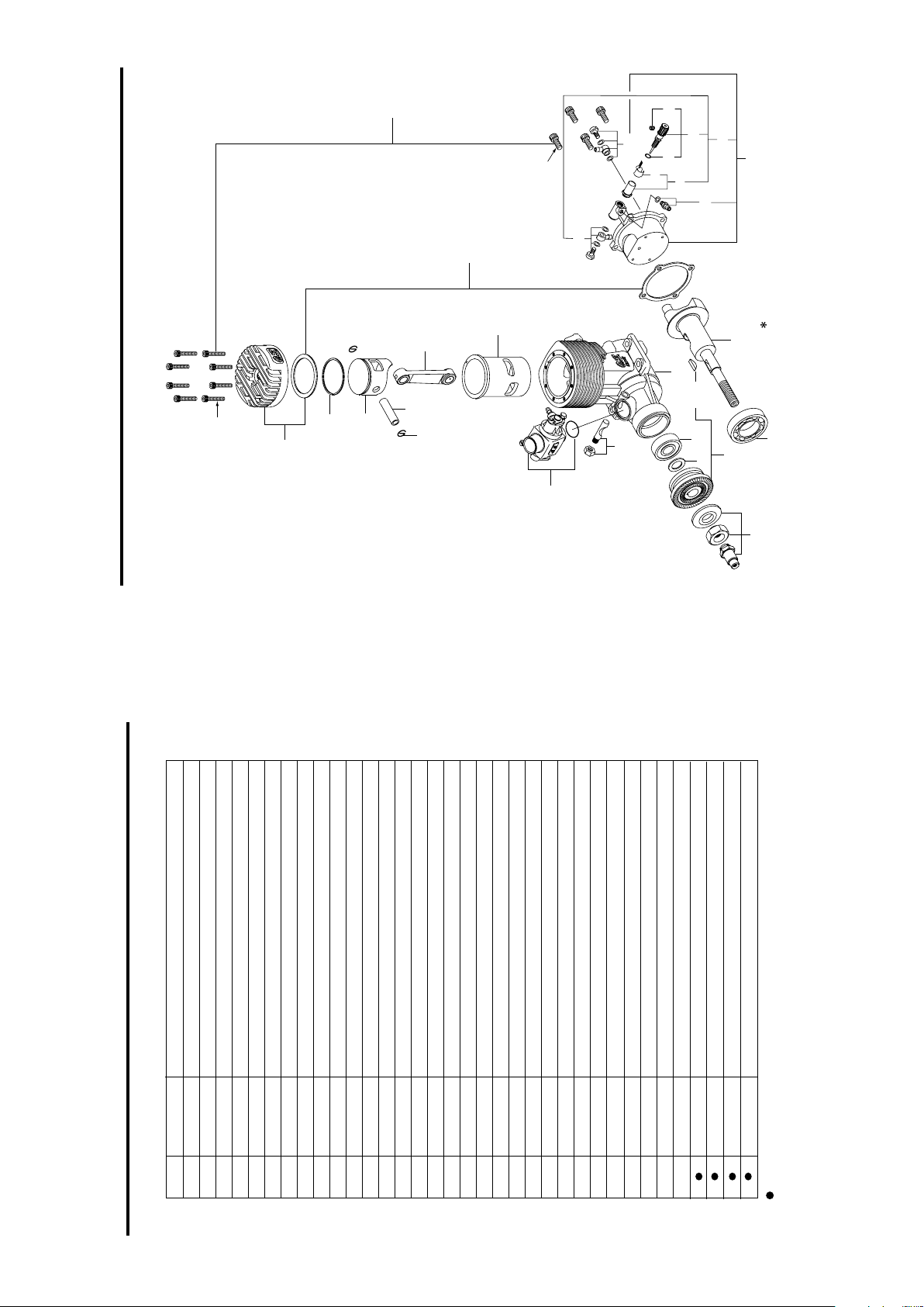
BASIC ENGINE PARTS
Cylinder Head
Drive Hub
Pump Unit PD-06
Lock Nut Set
Carburetor Type 70A
Cover Plate
Crankcase
Crankshaft
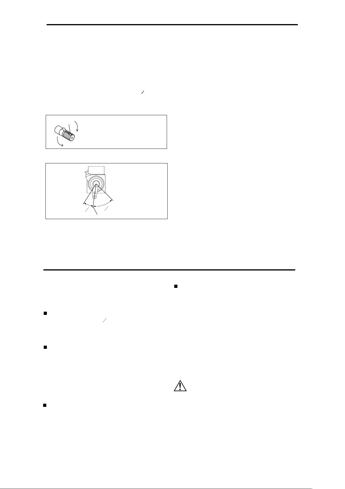
INSTALLING THE GLOW PLUG
Carefully insert plug, with washer,
fingertight only, b efore final
tightening with the correct size
plug wrench.
Glow plug
Washer

6
INSTALLATION
With any single-cylinder engine, it is preferable to bolt the
engine firmly to a body that has as much mass as
possible, in order to minimize loss of power due to engine
movement through vibration. However, the vibration that is
transmitted through the fuselage of an aircraft may,
dependent on the airframe construction, generate
considerable resonant sound.
For F3A competition purposes, in order to reduce this
vibration induced extra noise, it is now common to use a
so-called "soft mount", e.g. to isolate the engine mounting
from the actual fuselage structure with a resilient
material(e.g. rubber) in the form of grommets, bushes or
buffers.
Power loss
When a soft mount is used, full-throttle power output
may be reduced by the equivalent of 300 to 500 r.p.m.
under load, depending on the flexibility of the mounting.
Therefore, it is desirable to select a degree of rigidity
that will provide a reasonable compromise. The softer
the mount used, the better the noise reduction achieved
- but at the expense of greater power loss.
Throttle linkage
When the engine is throttled down to idling speed,
vibration amplitude, with a soft mount, is considerably
increased and this can result in fluctuation in the throttle
opening and erratic operation if the idle position of the
throttle rotor depends solely on the linkage to the servo.
Therefore, it may be advisable to use the throttle stop
screw on the carburetor, to positively fix the idling
position.
Note:
Fixing the idling setting with the throttle stop
screw, will also mean that the engine cannot be
stopped by retarding the throttle control trim
lever on the transmitter.
Installation of tuned silencer and exhaust header pipe
When a tuned silencer is firmly secured to the fuselage,
engine vibration will impose considerable strain on the
exhaust header pipe and, in extreme cases, the header
pipe may be damaged. It is advisable, therefore, to
insert some resilient material in the mountings for the
exhaust system, also.
Installation of cowling, etc.
When a soft mount is used, the engine may vibrate more
than expected. Make sure that the engine and spinner
do not touch the fuselage or cowling, otherwise,
overheating, additional noises and unreliable idling etc.,
may be caused.
Securing the engine
Be sure to secure the engine to the mount firmly, using'
4.5 - 5.0mm steel screws, such as Allen type, with
locknuts.
Remember to allow for some light spring compression in
the throttle linkage travel, so as to avoid stalling the servo
at the end of the throttle movement.
7
If the fitting of the "klunk" type fuel pick-up weight in the
fuel tank is incorrect, the weight may stick to the tank wall,
resulting in an irregular fuel flow to the carburettor, or,
alternatively, in the fuel flow being cut off during the course
of sharp aerobatic manoeuvres. Therefore, it is advisable
to make slots in the end of the weight, with a file or
hacksaw blade. Thoroughly wash out the weight to remove
any minute particles of metal before reinstalling it in the
tank.
FUEL TANK
Alternatively, a 'NON-BUBBLE WEIGHT' FUEL PICKUP(Code No.71531000) may be used. This is an improved
type of fuel pick-up weight which prevents air bubbles,
generated by engine vibration, from reaching the
carburettor and causing the engine to malfunction or stop.
It is available from O.S. stockists as an optional extra
part. A silicone-rubber O-ring surrounds the 'Bubbless'
pick-up weight to prevent internal damage to the fuel tank.
Use thick silicone tubing
10mm
For piping, use heavy duty silicone tubing of approximately
2.5mm bore and 5mm outer diameter. It is advisable to
secure connections with commercially available tube clips.
Tube lengths should be kept as short as possible. Take
care not to cause any kinks in the "plumbing".
PIPING
Connect to fuel tank
IN
OUT
PD-06
8
Below is an example of a typical installation. A muffler
pressurized fuel feed is not required.
It may be convenient to lead the pipes outside the fuselage
and connect with approx. 35mm(1-1/2") length of silicone
tubing, as shown.
When filling the tank from any position other than that
shown in the sketch, be sure to pinch the silicone tube with
a clip on the pump side to prevent fuel entering the pump.
Overflow
L-shaped nipple or
aluminum tubing
Silicone tubing
Disconnect here when filing the tank
Connect to "IN" nipple
of the pump
GLOWPLUGS
Since the compatibility of glowplug and fuel may have a
marked effect on performance and reliability, it would be
worthwhile to try different heat range glowplugs.
Recommended O.S. plugs are A5, No8 and TYPE F.
Carefully install the plug finger-tight, before final tightening
with the correct size plug wrench.
The role of the glowplug
With a glowplug engine, ignition is initiated by the
application of a 1.5-volt power source. When the battery is
disconnected, the heat retained within the combustion
chamber remains sufficient to keep the plug filament
glowing, thereby continuing to keep the engine running.
Ignition timing is 'automatic' : under reduced load, allowing
higher rpm, the plug becomes hotter and, appropriately,
fires the fuel/air charge earlier; conversely, at reduced rpm,
the plug become cooler and ignition is retarded.
Glowplug life
Particularly in the case of very high performance engines,
glowplugs must be regarded as expendable items.
Fit a plug suitable for the engine.
Use fuel containing a moderate percentage of
nitromethane unless more is essential for racing events.
Do not run the engine too lean and do not leave the
battery connected while adjusting the needle.
However, plug life can be extended and engine
performance maintained by careful use, i.e.:
9
Apart from when actually burned out, a plug may need to
be replaced because it no longer delivers its best
performance, such as when:
When to replace the glowplug
Filament surface has roughened and turned white.
Filament coil has become distorted.
Foreign matter has adhered to filament or plug body
has corroded.
Engine tends to cut out when idling.
Starting qualities deteriorate.
FUEL
Model engine fuel is poisonous. Do not allow it
to come into contact with the eyes or mouth.
Always store it in a clearly marked container
and out of the reach of children.
Model engine fuel is also highly flammable.
Keep it away from open flame, excessive heat,
sources of sparks, or anything else which
might ignite it. Do not smoke, or allow anyone
else to smoke, near to it.
Select, by practical tests, the most suitable fuel from
among the best quality fuels available in your country for
model use. For the best performance, a fuel containing 5%
to 20% nitromethane is preferable. Lubricants may be either castor-oil or a suitable synthetic oil ( or a blend of both )
provided that they are always of top quality.
For consistent performance and long engine life, it is essential to use fuel containing AT LEAST 18% lubricant by
volume. Some fuels containing coloring additives tend to
deteriorate and may adversely affect running qualities.
Once a satisfactory fuel has been selected and used for a
while, it may be unwise to needlessly change the brand or
type. In any engine, a change of fuel may cause carbon deposits in the combustion chamber or on the piston head to
become detached and lodged elsewhere, with the risk of
this causing unreliable operation for a while. If, however,
the adoption of a different fuel is unavoidable, check the
engine for the first few flights on the new fuel, by temporarily reverting to the running-in procedure.

10
PROPELLER
Use well balanced propellers only. Unbalanced propellers
cause increased vibration and loss of power. Determine
the best size and type after the engine has been run in.
Suggested propellers are high quality wood or glass
15x14-16 or 16x13-15. Final selection should be made, of
course, after test flights.
For safety, keep your face and other parts of the body well
clear of the propeller when starting the engine or when
adjusting the needle-valve while the engine is running.
Remember that, with the bigger propellers that this engine
is capable of turning, the blades cover a much larger area.
Refer again to the Warnings and Notes on the first page of
these instructions.
Never touch, or allow any object to come into
contact with, the rotating propeller and do not
crouch over the engine when it is running.
WARNING!
There is a risk, particularly with large capacity
engines, of the propeller flying off if the propeller nut
loosens due to detonation or "knocking", should the
engine be operated too lean or under too heavy a load.
Obviously, this can be very hazardous. To deal with
such risks, we have developed the special propeller
locknut assembly supplied with the MAX-140RX. This
prevents the propeller from flying off, even if the
propeller itself should slip or loosen.
Fit the 140RX safety locknut assembly as follows:
Fit the propeller to the engine shaft, followed by the
retaining washer and prop nut.
Tighten the nut with the 14mm wrench.
Finally, fit the locknut and tighten firmly with the 12mm
wrench, making sure that it locks into the propeller
retaining nut.
1.
2.
IMPORTANT:
With any engine, regardless of the type of propeller
attachment used, make a habit of checking prop
tightness before starting the engine. Remember that,
especially with wooden props, there is a tendency for
the material to shrink, or for it to be reduced by the
serrated face of the drive hub.
11
TUNED SILENCER
The O.S. Type T-6010 tuned silencer has been specially prepared for the MAX-140RX engine. It allows the engine to
develop high performance at lower engine r.p.m. (e.g.around 8,000r.p.m.) which enables the contest flyer to qualify for
noise reduction bonus points.
Here is an example of a combination with which maximum performance is obtainable at around 7,300-7,600r.p.m. You
may, of course, use other combinations, but it is recommended to refer to this combination as a starting point.
Propeller
Fuel
Exhaust Header Pipe
Tuned Silencer
Effective Pipe Setting
APC 16x14
Commercial good quality fuel
(10% nitromethane)
Actual length 240mm
(see sketch below)
O.S. Type T-6010
245mm (see sketch below)
Effective Header Pipe Setting ( 245mm)
Note :
Effective Header Pipe Setting means the distance from
the engine's exhaust flange to the entry to the tuned
silencer.
Header Pipe Length (245mm)
Center Line Length
5mm
Exhaust Header Pipe
Tuned Silencer
12
Adjusting effective header pipe length
Use the silicone tube sleeve supplied with the O.S. T -
6010 and connect the silencer and exhaust header
pipe together so that the effective pipe length is as long
as possible.
Start the engine, open the throttle and measure the
maximum r.p.m. at which the engine runs steadily for a
lengthy period. Then shorten the header pipe setting by
10mm and measure r.p.m. again. Repeat this
procedure, checking r.p.m. each time, until no further
increase in speed is recorded.
For other combinations or conditions, set the effective pipe
length as follows.
(Important : Make sure that the engine is adequately
run-in before operating it at full throttle for lengthy
Note: Be sure to use the same fuel and propeller while
making these checks.
r.p.m.
High
Start with this setting.
r.p.m.
Low
Long
Effective Header Pipe Length
Short
From this measured data, you will find a range of
settings through which r.p.m. do not vary significantly.
Set the header pipe length at the beginning of this range
(See diagram bottom left ) and fly the model.
If the pipe length is too short, the needle-valve
adjustment range at maximum r.p.m will be narrow, and
r.p.m. will tend to vary too much in the air, especially
when revolutions build up as load decreases. Also,
power will tend to drop off excessively against increased
load in the air. To correct this, increase the header
pipe's effective length.
Note:
Engine r.p.m. recorded on the ground are different from
those achieved in flight; not only because of increased
propeller loading when the aircraft is stationary, but also
because the cooling airflow over the engine and tuned
silencer is reduced. Therefore, optimum header pipe
adjustment should be finally set only after actual flight
tests. The power absorption of individual propellers of the
same size (dia. and pitch), even from the same
manufacturer, may differ quite markedly. This can cause
r.p.m. to vary between 300 and 500 with standard
propellers and between 100 and 200 with high quality
propellers. Therefore, it may be necessary to readjust the
header pipe length when a new propeller is fitted. Be sure
to check the r.p.m. in addition to the balance and pitch of
the propeller, before using it for flight.

12
Adjusting effective header pipe length
Use the silicone tube sleeve supplied with the O.S. T 6010 and connect the silencer and exhaust header
pipe together so that the effective pipe length is as long
as possible.
Start the engine, open the throttle and measure the
maximum r.p.m. at which the engine runs steadily for a
lengthy period. Then shorten the header pipe setting by
10mm and measure r.p.m. again. Repeat this
procedure, checking r.p.m. each time, until no further
increase in speed is recorded.
For other combinations or conditions, set the effective pipe
length as follows.
(Important : Make sure that the engine is adequately
run-in before operating it at full throttle for lengthy
Note: Be sure to use the same fuel and propeller while
making these checks.
r.p.m.
High
Start with this setting.
r.p.m.
Low
Long
Effective Header Pipe Length
Short
From this measured data, you will find a range of
settings through which r.p.m. do not vary significantly.
Set the header pipe length at the beginning of this range
(See diagram bottom left ) and fly the model.
If the pipe length is too short, the needle-valve
adjustment range at maximum r.p.m will be narrow, and
r.p.m. will tend to vary too much in the air, especially
when revolutions build up as load decreases. Also,
power will tend to drop off excessively against increased
load in the air. To correct this, increase the header
pipe's effective length.
Note:
Engine r.p.m. recorded on the ground are different from
those achieved in flight; not only because of increased
propeller loading when the aircraft is stationary, but also
because the cooling airflow over the engine and tuned
silencer is reduced. Therefore, optimum header pipe
adjustment should be finally set only after actual flight
tests. The power absorption of individual propellers of the
same size (dia. and pitch), even from the same
manufacturer, may differ quite markedly. This can cause
r.p.m. to vary between 300 and 500 with standard
propellers and between 100 and 200 with high quality
propellers. Therefore, it may be necessary to readjust the
header pipe length when a new propeller is fitted. Be sure
to check the r.p.m. in addition to the balance and pitch of
the propeller, before using it for flight.
13
If the pipe length is not set properly, the engine will not
only fail to develop its full performance but could also be
damaged through overheating.
If you wish to further reduce sound level, to meet extra
severe noise regulations, a larger(or coarser pitch)
propeller may be fitted to lower operating r.p.m. It will, of
course, be necessary to increase the header pipe length
accordingly.
Because noise generated by the engine and propeller
becomes louder as the r.p.m. increase, it is
environmentally desirable to run engines at reduced
r.p.m. for quieter operation, whenever possible.
Two adjustable controls are provided on the Type
70A carburetor.
CARBURETOR CONTROLS
The O.S. TYPE 70A carburetor has been designed
exclusively for use with the O.S. PD-06 fuel pump unit.
These two components, with appropriate plumbing
form the Pump System. O.S. Pump Systems offer the
twin advantages of increased power and the virtual
elimination of variation in fuel "head" at the
carburetor. The Type 70A carburetor has an extra large
throat, which improves breathing and increases
power. With normal suction fuel feed, or low-pressure
(exhaust) assisted fuel feed, such a large choke area
would be impracticable, but the special pump unit
ensures that fuel isdelivered to the carburetor at the
pressure required to maintain optimum mixture
strength, irrespective of fuel tank location or the
aircraft's attitude. These qualities are especially
valuablefor international class pattern aerobatic flying
and in models (including scale aircraft) where itmay be
difficult to locate the fuel tank close to the engine.
The Mixture Control Screw:
For adjusting the mixture strength at part-throttle and
idling speeds to obtain steady idling and smooth
acceleration.
The Throttle Stop Screw:
For setting the position where the carburetor rotor is
closed.
Throttle Stop Screw
Throttle Lever
Nipple
Mixture Control Screw
Mixture
Control Valve
Mixture
Control Valve Stopper
14
4
1
STARTING
Install an appropriate propeller and tighten securely.
To facilitate electric starting, fit an spinner for centring
the rubber drive insert of the starter.
Fill the fuel tank. Do not allow fuel to overflow into the
silencer, otherwise the engine may become flooded and
difficult to start.
Check that the needle-valve is closed. (Do not
overtighten.) Now open the needle-valve 1 turns from
the fully closed position and temporarily set the throttle
in the fully open position.
2
1
Turn needle-valve clockwise to close
(for leaner mixture)
Turn needle-valve counter-clockwise
to open (for richer mixture)
Mark
Close
Open
1.
2.
3.
4.
(When the 10-20% nitro fuel is used)
5. Open the throttle approx. one-quarter.
(This is to avoid unnecessarily
high r.p.m. when the engine
starts.)
Fully closed position
Fully opened position
Set at this point
4
3
Connect battery leads to glowplug.
Bring electric starter into contact with spinner and
depress starter switch for one or two seconds. Repeat if
necessary. When the engine starts, withdraw the starter
immediately.
7.
Attention :
Do not choke the carburetor air intake when applying the
starter. This could cause an excessive amount of fuel to
be drawn into the cylinder which may initiate an hydraulic
lock and damage the engine.
If the engine does not start within 10 repeat applications of
the starter, remove the glow-plug, check that it glows
brightly and that the cylinder is not flooded with fuel. (To
eject excess fuel, close needle-valve and apply starter with
glowplug removed.) Then try again.
8.
When the engine starts, advance the throttle stick slowly
checking the increase of r.p.m. Abrupt throttle operation
right after starting may cause the engine to stumble or
stop.
VERY IMPORTANT!
Before being operated at full power (i.e. at full-throttle and
with the needle-valve closed to its optimum setting) the
engine must be adequately run-in, otherwise there is a
danger of it becoming overheated and damaged.
6.
15
RUNNING-IN ("Breaking-in)
For long life and high-performance, this engine needs to
be properly "run in", or "broken-in". The following settings
apply when using a fuel containing not less than 15%
lubricant and not more than 10% nitromethane.
Needle-valve setting for starting
2
1
Open the needle-valve 1 turns from the fully closed
position. When using the optional fine-tapered needle
supplied with the engine, open the needle-valve
approx. 2 turns.
Bench or ground running
Preferably, use a propeller of slightly lower pitch than
the one intended for actual flight. Start the engine and
open the throttle. Close the needle-valve gradually and
allow the engine to run at its maximum r.p.m. for just
one or two seconds, then immediately reopen the
needle-valve a half-turn and run the engine with this
rich mixture for 5 to 6 seconds.
Repeat this procedure until the fuel tank is empty.
Idling adjustment
Start the engine with the needle-valve setting at the
original starting position. Close the needle-valve
gradually and set it at 1/8 to 1/4 turn opened from the
maximum r.p.m. position. Adjust the idling with this
needle-valve setting.
In-flight running-in
During the first 3 or 4 flights, try to avoid successive
nose-up manoeuvres. Since, during running-in, the
engine will tend to overheat, set the needle-valve
carefully so that the mixture is always slightly rich. If the
mixture becomes lean during a nose-up manoeuvre
such as a loop, land the model and open the needlevalve 1/8 to 1/4 turn. If the engine becomes too rich
during level flight with this needle-valve setting, increase
the header pipe setting 10 to 20mm and re-set the
needle-valve. At least 10 flights are required for the
completion of running-in. Note that the engine will
develop its full performance only after running-in is
completed.
Model engines generate considerable heat.
Do not touch any part of your engine until it
has cooled. Contact with the muffler (silencer),
cylinder head or exhaust header pipe, in
particular, may result in a serious burn.
16
2
1
Note:
It is important to be able to run the engine on a rich
mixture during the breaking-in period to avoid
overheating. If the fuel/air mixture does not become
sufficiently rich, even when the needle-valve is opened
more than 5 turns, first check that the carburetor has
not become clogged with dirt or fluff. Also check that
the fuel tubing has not become holed or split and that
the fuel pick-up weight is not sticking to the tank wall.
(See previous reference to 'FUEL TANK'.) If, at any
time, the engine cannot be persuaded to run rich after
checking the above, it is possible that a fault has
developed in the pump. In this case, consult the O.S.
engine distributor in your country.
As the running-in proceeds, a slightly different idling
mixture will be required for best carburetor performance.
Therefore, adjust the mixture control valve accordingly.
During the first few (running-in) flights, the engine may
sometimes stop because the carburetor adjustments have
yet to be finalized at this stage. Be prepared, therefore,
to make an emergency landing at this time.
MIXTURE CONTROL ADJUSTMENT
Before starting the engine, open the Needle-Valve 1
turns from the fully closed position.
(When the 10-20% nitro fuel is used)
Set the throttle very slightly open from the idle position
and start the engine in the usual way. It is preferable to
have the throttle only slightly open, to avoid
unnecessarily high revolutions when the engine starts.
Now open the throttle fully and gradually close the
Needle-Valve until the engine is running at its maximum
speed.
Do not close the Needle-Valve to too lean a setting, as
this will cause overheating which may result in internal
damage and reduced engine life. Set the Needle-Valve
approximately 3 to 4 clicks open (i.e."rich" ) from the
peak r.p.m. setting, even though this will slightly reduce
r.p.m. on the ground.
Make sure that the engine is fully "run-in" before
operating it continuously at full power.
Having set the Needle-Valve as described above, close
the throttle. The engine should idle steadily and
continuously. (If it stops immediately, first try turning the
Throttle Stop Screw clockwise a few degrees to raise
the idling speed a little.)
17
Note:
If, however, the engine idles unevenly and smokes a
good deal when the throttle is re-opened, before picking
up speed, it is probable that the idling mixture is too rich.
In this case it will be necessary to turn the Mixture
Control Screw clockwise about 5 degrees.
Alternatively, if the Mixture Control Screw is set too
lean, the engine may stop when the throttle is closed, or
it may idle for a few moments, then speed up very
slightly before coming to a stop. Re-opening the throttle
under these conditions will usually result in the engine
cutting out abruptly, without smoking. Corrective action
is to turn the Mixture Control Screw about 5 derrees
counter-clockwise. out readjustments progressively and
patiently, remembering the symptoms of rich and lean
running, quoted above, until the engine responds
quickly and positively to the throttle.
Once the correct carburetor settings have been
established, it should be unnecessary to alter them.
Such slight readjustments may be necessary for
optimum performance if defferent types of fuel,
glowplugs or propellers used.
PD-06 FUEL PUMP - WARNING!
Never disassemble the pump
If the pump is dismantled, its
original performance may not be
restored.
Never move the screw on the pump
This is precisely adjusted at the factory. If the
screw is disturbed, it cannot be re-set at its
optimum position without using special measuring
instruments.
Any foreign matter entering the Pump System may
interfere with its correct functioning and may even
damage the pump diaphragm. Be sure to filter all fuel
before filling the tank and, most important, use a good
quality fine filter in the delivery tube between the tank
and pump.
Use fuel filters
Never attempt to "clean-out" the inlet and outlet
nipples with a sharp instrument, such as a pin or
thin wire.
This will damage the pump
and render it inoperative.
In case of a pumped engine, if the needle-valve is too
much opened, at acceleration mixture seems to be rich
even if idling mixture is lean. If the idling mixture is too
lean, the engine will stop with prolonged idling (more
than 30 seconds). In this case, adjust the mixture
control valve to richer side and close the needle-valve to
the appropriate point.

18
ENGINE CARE AND MAINTENANCE
As noted above, foreign matter in the fuel used may cause
malfunctioning of the pump and/ or carburetor. Be sure
to use a high quality fuel filter between the refuelling
can and fuel tank. The O.S. Super Filter (L) is available
as an optional extra part. The Super Filter (L) is fitted
inside the fuel can at the outlet and has a special double
filter element to ensure that the fuel tank is always
supplied with clean fuel.
Be sure to check the carburetor at least once every 30
flights. Remove the needle- valve holder from the
carburetor, using the appropriate open-ended wrench, and
extract any foreign matter that may have lodged in the
threaded part of the carburetor body. Minute particles of
foreign matter may upset mixture strength, so that engine
performance becomes erratic and unreliable. Remember
that obstruction to fuel flow may also cause the engine
to become overheated, resulting in internal damage.
If, after use, the fuel system is left unattended for a lengthy
period, there will be a tendency for the methanol content
of the fuel to evaporate sufficiently for the oil content to
"gum" the internal parts of the pump. Therefore, it is
advisable, at the end of the day's flying, to empty the
fuel-tank, invert the engine and pump out the remaining
fuel in the system by rotating the propeller until no more
fuel is ejected from the carburetor. If the pump is not in
use for a while (more than one month), remove the pump
and wash out its interior by injecting methanol through
the " IN" nipple. Fit the sealing cap (provided) to the
nipples, after draining out the methanol.
Note :
Kerosene will cause swelling and rapid deterioration
of the fuel tubing. Do not, therefore, use kerosene
for cleaning this engine.
At the end of each operating session, drain out any fuel
that may remain in the fuel tank.
Next, energize the glowplug and try to restart the engine to
burn off any fuel that may remain inside the engine. Repeat this procedure until the engine fails to fire. Remove
the glowplug and eject any residue by rotating the engine
with an electric starter for 4 to 5 seconds while the engine
is still warm.
Finally, inject some corrosion inhibiting after-run oil into the
engine. Rotate the engine a few times by hand, to make
sure that it is free, and then with an electric starter for 4 to
5 seconds to distribute the oil to all the working parts.
Do not inject corrosion inhibiting after-run oil into the
carburetor as this may cause the O-ring inside the carburetor to deteriorate.
These procedures will reduce the risk of starting difficulties
and of internal corrosion after a period of storage.
Note:
19
29015019
27681340
22681953
27881330
29481300
29481100
27881800
27881810
27881820
29481600
29481200
27881400
N.+M3X6
No.
1
2
3
3-1
4
5
6
7
8
9
3-2
3-3
Carburetor Gasket
Mixture Control Valve Stop Screw
Fuel Inlet
Mixture Control Screw
Rotor Stopper
Carburetor Body
"O"Ring(S) (2pcs.)
"O"Ring(L) (2pcs.)
"O"Ring (2pcs.)
Mixture Control Valve Assembly
Carburetor Rotor
Throttle Lever Assembly
Description
Code No.
The specifications are subject to alteration for improvement without notice.
70A CARBURETOR EXPLODED VIEW & PARTS LIST
Type of screw
C...Cap Screw M...Oval Fillister-Head Screw
F...Flat Head Screw N...Round Head Screw S...Set Screw
1
2
3
3-1
3-2
3-3
4
5
6
7
8
9
20
C.M3.5x18
C.M4x10
1
3
2
4
5
6
7
8
9
10
11
12
13
11-1
14
15
16
17
18
18-1
18-2
18-3
18-4 18-5
18-6
18-7
18-9
18-8
19
Type of screw
C...Cap Screw M...Oval Fillister-Head Screw
F...Flat Head Screw N...Round Head Screw S...Set Screw
ENGINE EXPLODED VIEW
20
C.M3.5x18
C.M4x10
1
3
2
4
5
6
7
8
9
10
11
12
13
11-1
14
15
16
17
18
18-1
18-2
18-3
18-4 18-5
18-6
18-7
18-9
18-8
19
Type of screw
C...Cap Screw M...Oval Fillister-Head Screw
F...Flat Head Screw N...Round Head Screw S...Set Screw
ENGINE EXPLODED VIEW
21
ENGINE PARTS LIST
The specifications are subject to alteration for improvement without notice.
22681980
71605100
29213000
22681953
45571000
26711305
27381940
26381501
24981837
29481970
29481900
45571100
72507000
29414000
29402000
46030008
29081719
29401000
29431000
45520000
45508200
29408000
45910200
29481000
29403100
29405000
28117000
29406000
29403200
29403400
29404000
No.
Description
Code No.
123456789
10
11
11-1
12131415161718
18-1
18-2
18-3
18-4
18-5
18-6
18-7
18-8
18-9
19
72102100
72102110
72102120
72102180
Exhaust Adaptor "O" Ring
Exhaust Adaptor
Exhaust Header Pipe
Exhaust Header Pipe Assembly
Needle
Glow Plug A5
Screw Set
Fuel Outlet
Universal Nipple(S3.5)
Ratchet Spring
Needle Valve Holder Assembly
Set Screw
"O" Ring(2pcs.)
Needle
Needle Valve Assembly
Universal Nipple(L3.5)
Pump Unit PD-06
Gasket Set
Crankshaft
Crankshaft Ball Bearing(Rear)
Carburetor Retainer
Crankcase
Crankshaft Ball Bearing(Front)
Thrust Washer
Woodruf Key
Drive Hub
Lock Nut Set
Carburetor Complete(70A)
Cylinder Liner
Connecting Rod
Piston Pin Retainer(2pcs.)
Piston Pin
Piston
Piston Ring
Cylinder Head
With exhaust header pipe
22
No.8
(71608001)
(72403050)
(71531000)
(71521000)
(45910300)
(55500004)
M5
(71615009)
TYPE F
(72102100)
(72104200)
(27984000)
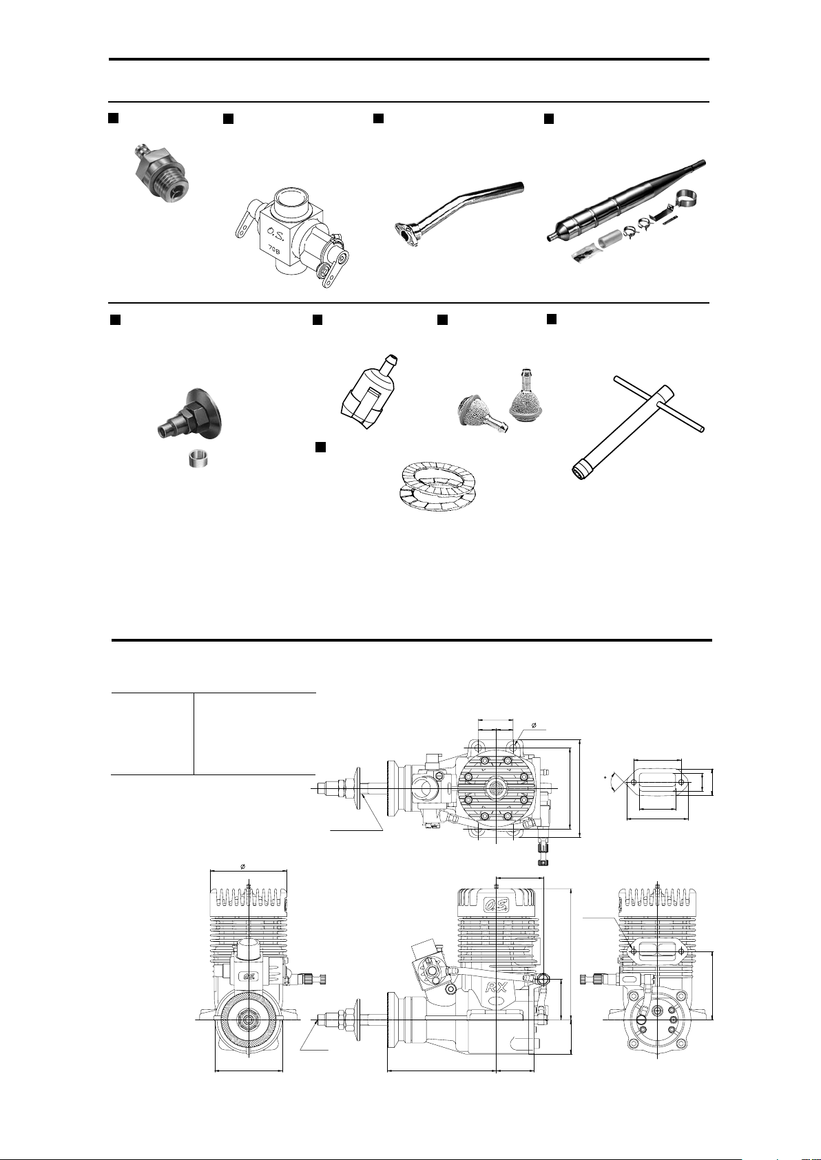
GENUINE O.S. PARTS & ACCESSORIES
GLOW PLUGS
PROPELLER LOCKNUT SET
FOR TRUTURN SPINNER
SUPER FILTER
NON-BUBBLE
WEIGHT
LONG SOCKET WRENCH
WITH PLUG GRIP
LOCK WASHER
(10Sets )
MIXTURE CONTROL
CARBURETOR 70B
EXHAUST HEADER PIPE
T-6010 TUNED SILENCER
(L)
23
23.0cc / 1.404cu.in.
32.0mm / 1.260in.
28.6mm / 1.126in.
1.800-10.000r.p.m.
3.5ps / 3.55hp / 9.000r.p.m.
830g / 29.3oz.
■
■
■
■
■
■
THREE VIEW DRAWING
Dimensions(mm)
SPECIFICATIONS
Displacement
Bore
Stroke
Practical R.P.M.
Power output
Weight
INOUT
PD-06
140
MADE IN JAPAN
25
58
70
4- 5.1
27
78
49
2-M4X0.7
UNF 5/16-24
48.4
93.9
13 12
34
26
44
13
19
90
55
M4X0.7
33.6
24.5
29
24
MEMO
C
Copyright 2002 by O.S.Engines Mfg. Co., Ltd. All rights reserved. Printed in Japan.
60090850 061102
U
N
E
Q
U
A
L
L
E
D
Q
U
A
L
I
T
Y
P
R
E
C
I
S
I
O
N
&
P
E
R
F
O
R
M
A
N
C
E
E
S
T
A
B
L
I
S
H
I
N
G
T
H
E
S
T
A
N
D
A
R
D
S
O
F
E
X
C
E
L
L
E
N
C
E
TEL. (06) 6702-0225
FAX. (06) 6704-2722
6-15 3-Chome Imagawa Higashisumiyoshi-ku
Osaka 546-0003, Japan
URL : http://www.os-engines.co.jp
 Loading...