

O.S. engine MAX-12TG-P, MAX-12TG, MAX-12TG-X, MAX-12TG-PX Instruction Manual

It is of vital importance, before attempting to operate
your eng ine, to read the gene ral 'SA FETY
INSTRUCTIONS AND WARNINGS' section on
pages 2-5 of this booklet and to strictly adhere to the
advice contained therein.
Also, please study the entire contents of this
instruction manual, so as to familiarize yourself
with the controls and other features of the engine.
Keep these instructions in a safe place so that you
may readily refer to them whenever necessary.
It is suggested that any instructions supplied with
the vehicle, radio control equipment, etc., are
accessible for checking at the same time.
JAPAN
1
2-5
6-7
8
9
10-11
12
13-15
16
17
18-19
20-26
27-30
31-34
35-37
38-45
46-49
50-52
53-56
CONTENTS
SAFETY INSTRUCTIONS AND
WARNINGS ABOUT YOUR O.S. ENGINE
ENGINE CONSTRUCTION, NOTES WHEN
APPLYING AN ELECTRIC STARTER
INSTRUCTIONS
BASIC ENGINE PARTS
TOOLS, ACCESSORIES, etc.
STANDARD ACCESSORIES
CARBURETOR CONTROLS,
INSTALLATION OF THE CARBURETOR
NOTES CONCERNING THE RECOIL STARTER
GLOWPLUG
ENGINE INSTALLATION
STARTING THE ENGINE &
RUNNING-IN ('Breaking-in)
FINAL ADJUSTMENT
TROUBLE SHOOTING
CARE AND MAINTENANCE
EXPLODED ENGINES VIEWS &
PARTS LIST
CARBURETOR EXPLODED VIEW &
PARTS LIST
O.S. GENUINE PARTS & ACCESSORIES
THREE VIEW DRAWING
2
!
!
Remember that your engine is not a "toy", but a highly efficient internalcombustion machine whose power is capable of harming you, or others, if it is
misused. As owner, you, alone, are responsible for the safe operation of your
engine, so act with discretion and care at all times.
If at some future date, your O.S. engine is acquired by another person, we would
respectfully request that these instructions are also passed on to its new owner.
SAFETY INSTRUCTIONS AND WARNINGS ABOUT YOUR O.S. ENGINE
The advice which follows applies basically to ALL MODEL ENGINES and is
grouped under two headings according to the degree of damage or danger
which might arise through misuse or neglect.
WARNINGS
NOTES
These cover events which might involve
serious (in extreme circumstances, even
fatal) injury.
These cover the many other possibilities,
generally less obvious sources of danger,
but which, under certain circumstances,
may also cause damage or injury.
3
!
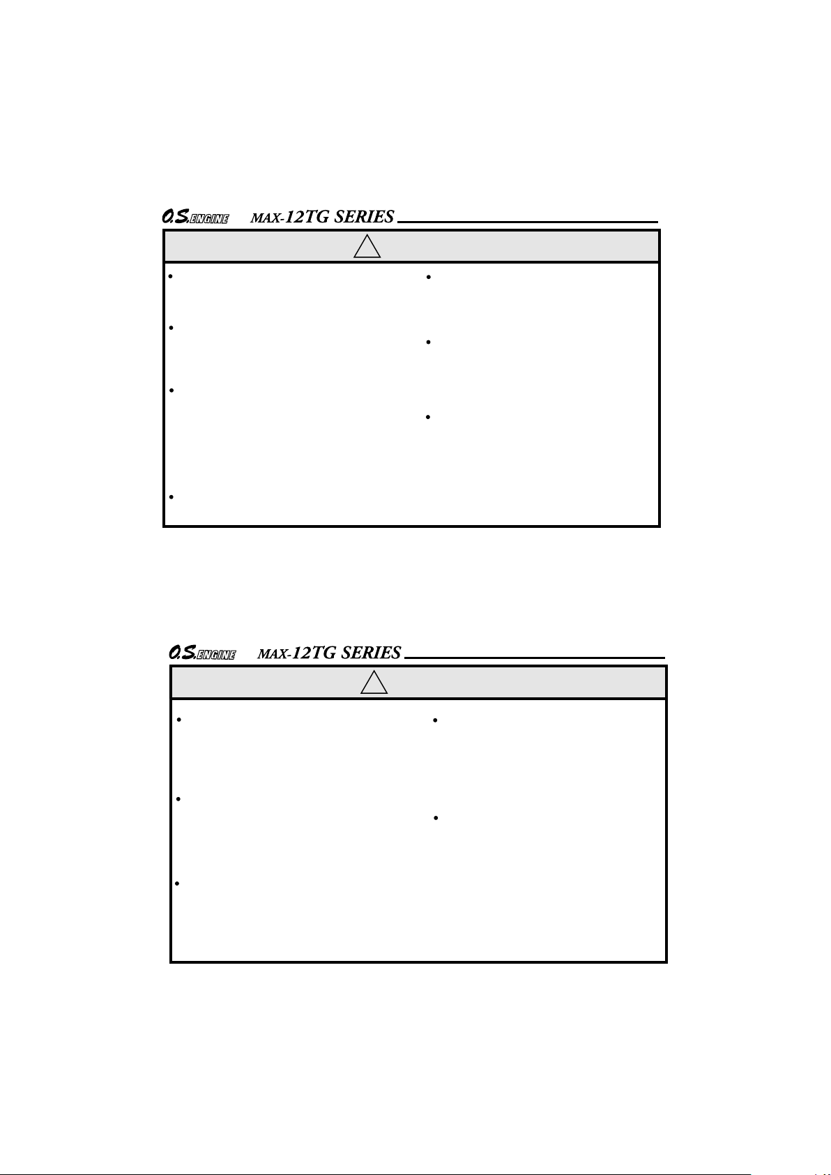
WARNINGS
Model engine fuel is poisonous. Do not allow it to
come into contact with the
eyes or mouth. Always store
it in a clearly marked container and out of the reach
of children.
Model engine fuel is also
highly flammable. Keep it
away from an open flame,
excessive heat, sources of
sparks, or anything else
which might ignite it. Do not
smoke or allow anyone else
to smoke, near to it.
Never operate your engine in an enclosed space. Model engines, like
automobile engines, exhaust deadly
carbon-monoxide. Run your engine
only in an open area.
Model engines generate
considerable heat. Do not
touch any part of your
engine until it has cooled.
Contact with the muffler
(silencer), cylinder head
or exhaust header pipe, in
particular, may result in a
serious burn.
•
•
•
•
4
!
NOTES
Before starting the engine, always check
the tightness of all the screws and nuts
especially those of joint and movable
parts such as throttle arm. Missing
retightening the loose screws and nuts
often causes the parts breakage that is
capable of harming you.
This engine is intended for model cars.
Do not attempt to use it for any other
purpose.
Mount the engine in your model
securely, following the manufacturer's
recommendations, using appropriate
screws and locknuts.
Install an effective silencer (muffler).
Frequent close exposure to a noisy
exhaust (especially in the case of the
more powerful highspeed engines) may
eventually impair your hearing and such
noise is also likely to cause annoyance
to others over a wide area.
The wearing of safety glasses is also
strongly recommended.
Take care that the glowplug clip or
battery leads do not come into contact
with rotating parts. Also check that the
linkage to the throttle arm is secure.
For their safety, keep all onlookers
(especially small children) well back (at
least 20 feet or 6 meters) when
preparing your model for running.
5
!
NOTES
To stop the engine, fully retard the
throttle stick and trim lever on the transmitter, or, in an emergency, cut off the
fuel supply by pinching the fuel delivery
line from the tank.
Warning! Immediately after a glowplugignition engine has been run and is still
warm, conditi ons s ometimes exist
whereby it is just possible for the engine to
abruptly restart if it is rotated over
compression WITHOUT the glowplug
battery being reconnected.
Pull the operating handle straight out
when starting the engine, so that the cord
does not rub against the vehicle body or
engine. This will help prevent the cord
from being damaged by abrasion or
engine heat.
Do not extend the starter cord more than
40cm (16"). Do not abruptly release the
operating handle. Allow the cord to
rewind smoothly while still holding the
handle.
Do not attempt to disassemble the recoil
starter of the 12TG-X and 12TG-PX.
If you do so, the very strong spring inside
will be suddenly ejected. This can be
very dangerous.
6
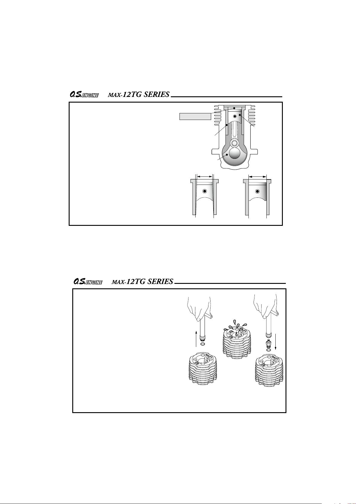
Piston
Cylinder Liner
Crankshaft
ENGINE CONSTRUCTION
With this engine, the piston
will feel tight at the top of its
stroke (TDC) when the engine
is cold. This is normal. The
cylinder bore has a slight
taper. The piston and cylinder
are designed to achieve a
perfect running clearance
when they reach operating
temperature.
Near TDC
Slight taper
When the engine is cold.
When the engine is hot.
7
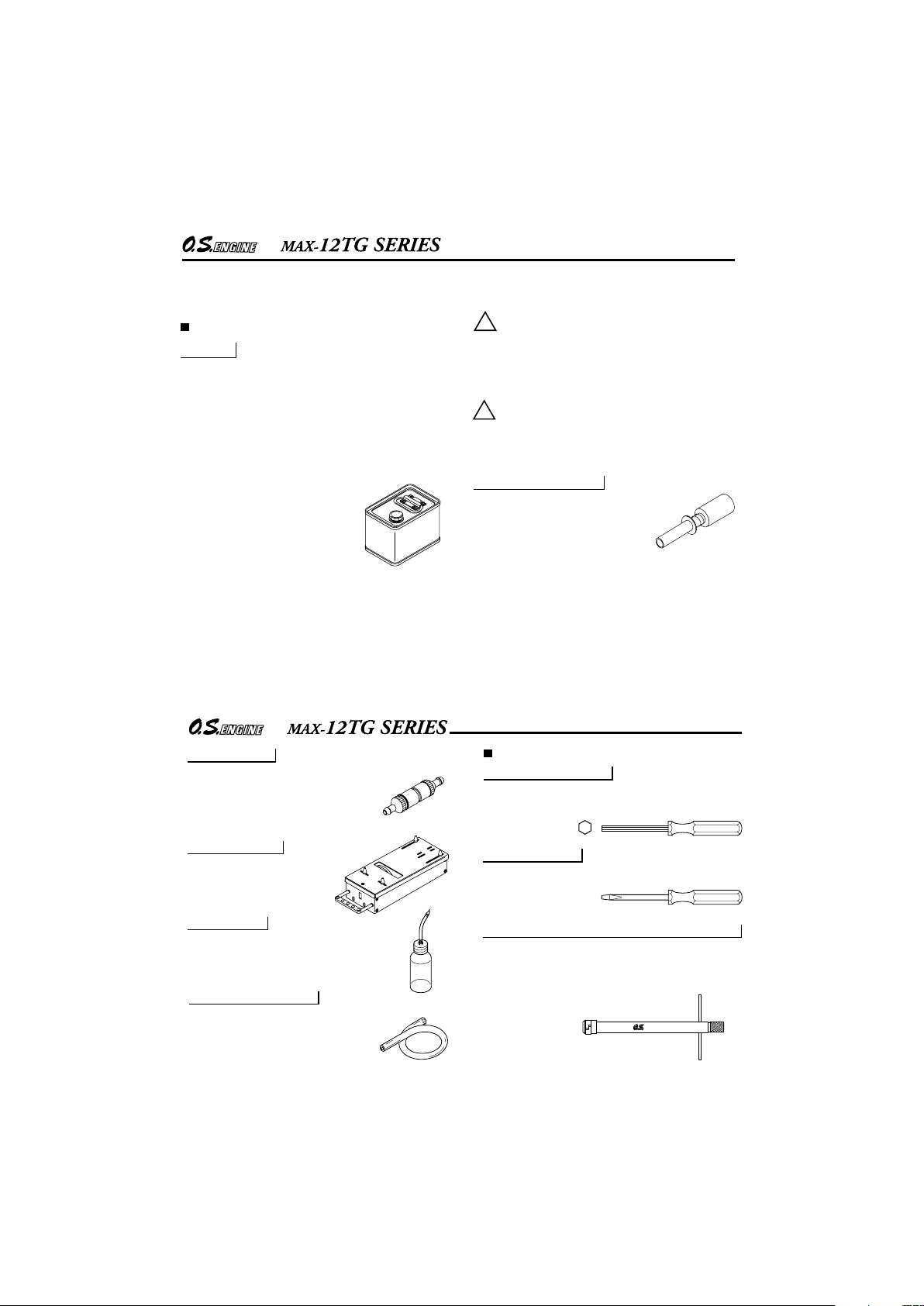
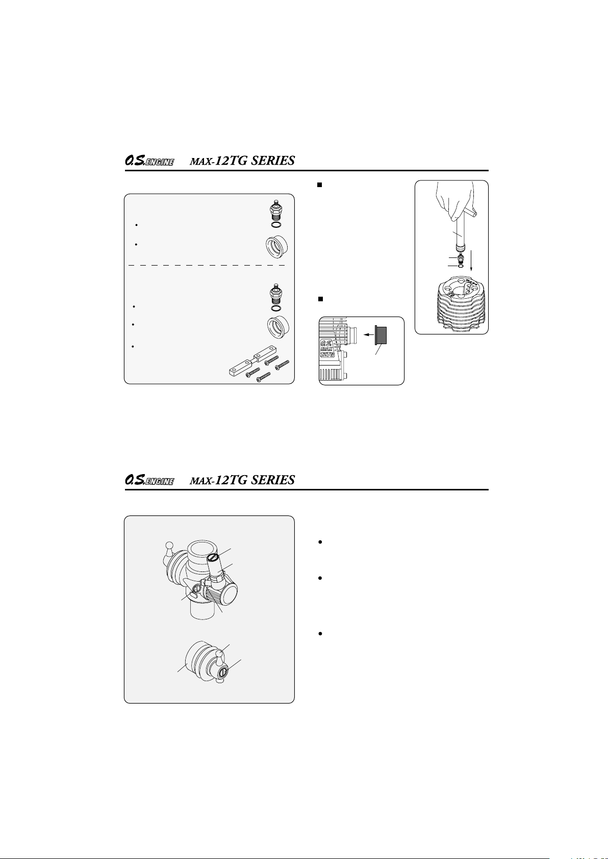
NOTES WHEN APPLYING
AN ELECTRIC STARTER
Do not over-prime. This could
cause a hydraulic lock and damage
the engine on application of the
electric starter.
If over-primed, remove glowplug,
close needle-valve and apply
starter to pump out surplus fuel.
Cover the head with a rag to
prevent any pumped out fuel from
getting into your eyes.
Remove the glowplug.
Pump out surplus fuel.
Install the glowplug.

8
This manual handles the following five
versions.
MAX-12TG SERIES INSTRUCTIONS
NOTE
As delivered, the engine has its
carburetor lightly fit into its intake.
Secure it according to the INSTALLATION
OF THE CARBURETOR section.
MAX-12TG
with 12E carburetor
MAX-12TG-X
with 12E carburetor
MAX-
12TG-P
with 12D carburetor
MAX-
12TG-PX
with 12D carburetor
The 12TG Series engines are developed for
1/10 scale R/C cars. They are rear exhaust
engines designed for sport use.
For easier handling, the engines are
equipped with a newly designed 12E or 12D
carburetor. An O.S. No.8 glowplug is also
supplied with the engines. The 12E and 12D
engines have mild and smooth accelerating
characteristics most suitable for sport
running. Recoil starter incorporated
versions which eliminate the need for a
separate electric starter and starter battery
are also available.
MAX-12TG-P
with 12E carburetor
9
MAX-12TG-PX
MAX-12TG
Heatsink Head
Crankcase
Mounting Lugs
Exhaust
Cover Plate
Carburetor
Type 12E
Crankshaft
BASIC ENGINE PARTS
Heatsink Head
Drive Hub
Carburetor
Type 12D
Crankshaft
Crankcase
Mounting Lugs
Exhaust
Starter Handle
Recoil Starter
Assembly No.N1
Rear Adaptor
10
Items necessary for starting
TOOLS, ACCESSORIES, etc.
The following items are necessary for operating the
engine.
FUEL
Generally, it is suggested that the user selects a fuel
that is commercially available for model two-stroke
engines and contains 10-30% nitromethane.
As a starting point, we recommend a fuel containing
20% nitromethane, changing to a fuel containing more
nitro if necessary. When the brand of fuel is changed,
or the nitro content increased, it is advisable to repeat
the running-in procedure referred to in the RUNNINGIN paragraphs.
Please note that with high-nitro fuels,
although power may be increased for
com pe tition purposes , glow pl ug
elements do not last as long and
engine life will be shorter.
!
REMINDER!
Model engine fuel is poisonous. Do not
allow it to come into contact with the eyes
or mouth. Always store it in a clearly
marked container and out of the reach of
children.
!
Model engine fuel is also highly flammable.
Keep it away from open flame, excessive
heat, sources of sparks, or anything else
which might ignite it. Do not smoke or allow
anyone else to smoke, near to it.
GLOWPLUG IGNITER
Commercialy available handy
glowplug heater in which the
glowplug battery and battery leads
are integrated.
11
FUEL PUMP
For filling the fuel tank, a simple, polyethylene "squeeze" bottle, with a suitable spout, is required.
FUEL FILTER
To be installed in the fuel line between
fuel tank and carburetor to prevent
foreign matter from entering the
carburetor.
STARTER BOX
For starting the engine.
It is not necessary for 12TG-X
and 12TG-PX.
SILICONE FUEL LINE
Heatproof silicone tubing of approx.
5mm o.d. and 2mm i.d. is required for
the connection between the fuel tank
and engine.
TOOLS
HEX SCREWDRIVER
SCREWDRIVER
Necessary for engine installation.
1.5mm, 2mm, 2.5mm, 3mm
Necessary for carburetor adjustments.
No.1, No.2, etc
LONG SOCKET WRENCH WITH PLUG GRIP
Recommended for easy removal and replacement of
the angled and recessed glowplug, the O.S.Long
Socket Wrench incorporates a special grip.
12
MAX-
12TG,
MAX-
12TG-P
Standard accessories
Engine Mount Spacer 1piece
Glow Plug No.8 1piece
Exhaust Seal Ring 1piece
MAX-12TG-X, MAX-12TG-PX
Glow Plug No.8 1piece
Exhaust Seal Ring 1piece
INSTALLING THE
GLOWPLUG
Fit washer to glowplug and
insert carefully into cylinderhead, making sure that it is
not cross-threaded before
tightening firmly.
Install the exhaust seal
ring supplied.
Exhaust
Seal Ring
Glowplug
Socket
Wrench
Washer
Use it when the engine interferes
with the car chassis.
13
CARBURETOR CONTROLS
The Needle-Valve(Adjusted at the factory):
Three adjustable controls are provided on this
carburetor.
For adjusting the mixture strength when the throttle
is fully open.
The Throttle Stop Screw
(Adjusted at the factory):
For setting the minimum idle speed:
For adjusting the mixture strength at part-throttle
and idle speed, to obtain steady idling and smooth
acceleration to mid speed.
The Metering Needle
(Adjusted at the factory):
NOTE : Readjustment may b e n ecessary,
occasionally to allow for changes in fuel formula,
gear ratio or clutch engagement point.
Metering Needle
Throttle Stop
Screw
Needle Valve
Ball Link No.5
Dust Cover
Carburetor Type 12D
Fuel Inlet
Needle Holder
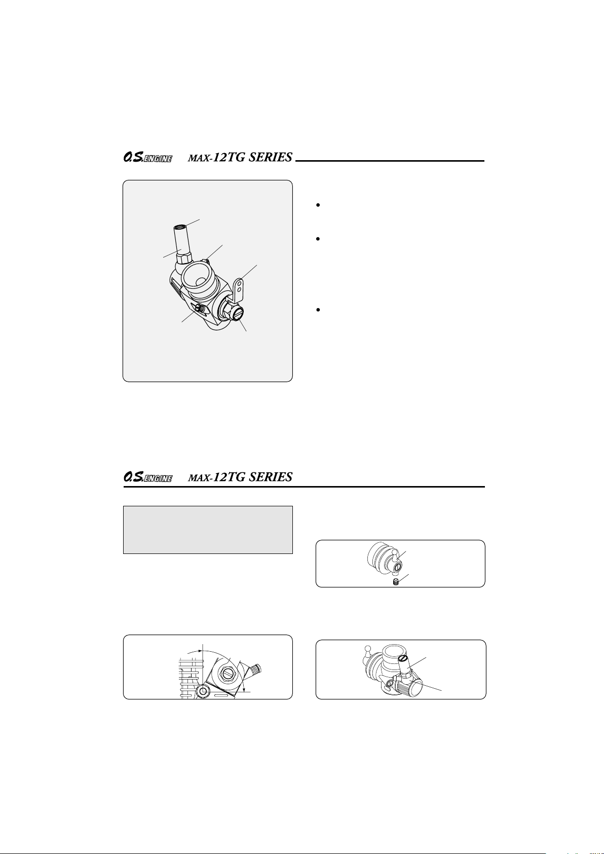
14
Carburetor Type 12E
Mixture Control Screw
Throttle
Stop Screw
Needle Valve
Needle Holder
Fuel Inlet
Throttle Lever
The Needle-Valve(Adjusted at the factory):
Three adjustable controls are provided on this
carburetor.
For adjusting the mixture strength when the throttle
is fully open.
The Throttle Stop Screw
(Adjusted at the factory):
For setting the minimum idle speed:
For adjusting the mixture strength at part-throttle
and idle speed, to obtain steady idling and smooth
acceleration to mid speed.
The Mixture Control Screw
(Adjusted at the factory):
NOTE : Readjustment may b e n ecessary,
occasionally to allow for changes in fuel formula,
gear ratio or clutch engagement point.
(It should be screwed in or out less tan one turn.)
15
INSTALLATION OF THE CARBURETOR
As delivered, the engine has its carburetor lightly fit into
the intake boss. Secure it as follows.
Rotate the retainer screw gently until it stops, then
tighten a further 60-90˚. Do not overtighten the
screw as this will damage the carburetor body.
1.
Rotate the retainer nut
gently until it stops.
Tighten a further 60-90˚
Fuel Inlet
Needle
Holder
Ball Link
Retaining Screw
Loosen the retainer screw, rotate the carburetor to
its correct position and make sure that it is
pressed well down into the intake boss,
compressin g the rubb er ga sket, before
retightening the screw.
NOTE
As delivered, the engine has its carburetor
lightly fit into its intake. Secure it changing its
angle according to the car chassis.
2.
When changing the ball link direction, loosen the
retaining screw with a 1.5mm Hex wrench.
After changed the fuel inlet direction, tighten the
needle holder slowly and gently until it stops. Then,
tighten 45~60 degrees further. Do not tighten further
or the fuel inlet will be distorted, which may result in
fuel leaking.
16
!
!
!
◆
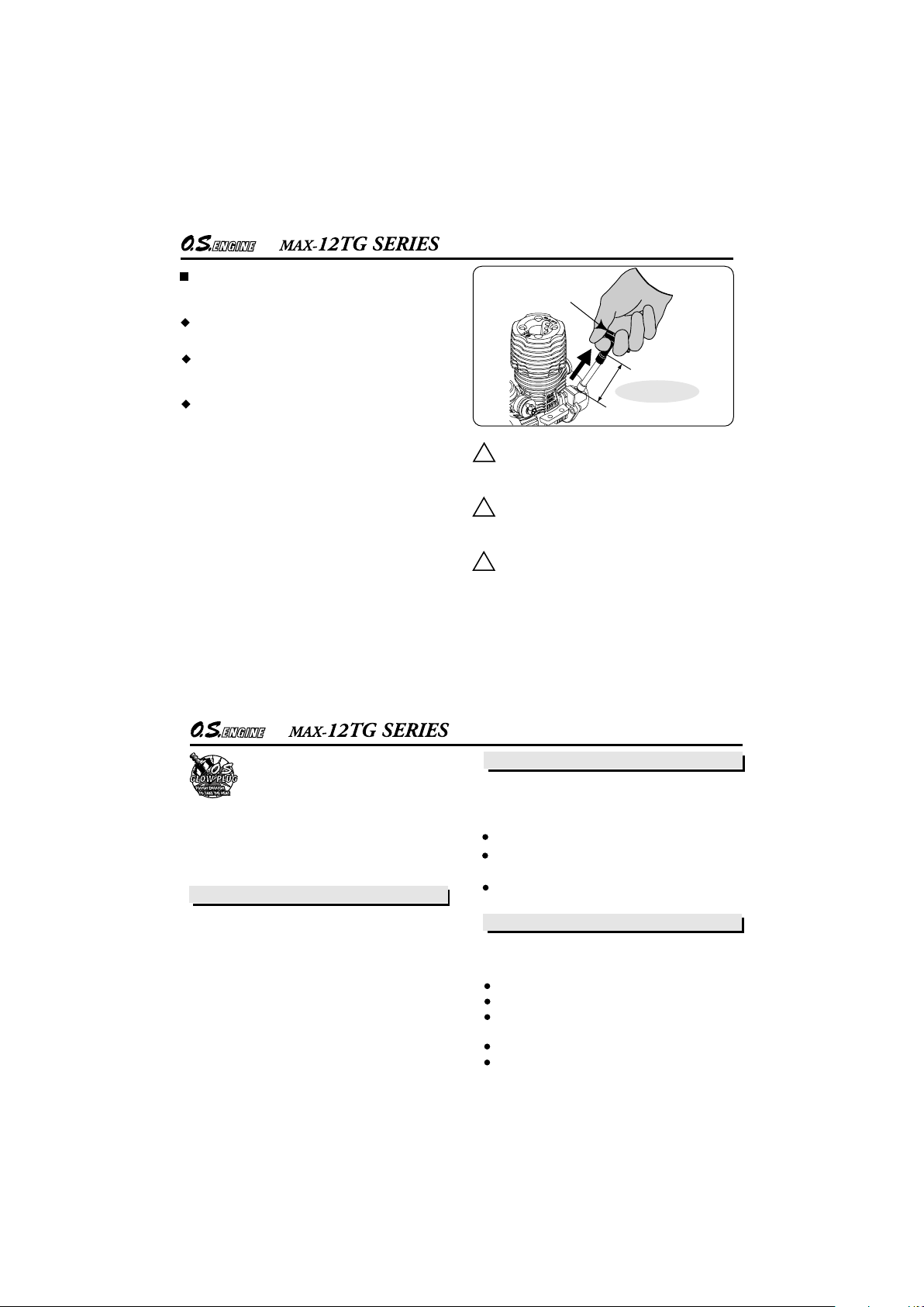
NOTES CONCERNING THE RECOIL STARTER
REMINDER!
Do not attempt to disassemble the recoil
starter. If you do so, the very strong spring
inside will be suddenly ejected. This can be
very dangerous.
Do not extend the starter cord more than
40cm (1 6"). Do not abruptl y rele ase the
operating handle. Allow the cord to rewind
smoothly while still holding the handle.
Pull the operating handle straight out when
starting the engine, so that the cord does not
rub against the vehicle body or engine.
This will help prevent the cord from being damaged
by abrasion or engine heat.
Try to avoid spilling fuel over the starter unit and its
cord. Some fuels have a detrimental effect on these
parts.
The starter prevents the engine from being rotated
in the wrong direction.The unit will be damaged if you
attempt to force the flywheel in the opposite direction (i.e. clockwise when viewed from the crankshaft
end).
Starter Handle
16" 40cm MAX!
It is suspected that the engine is over-primed when
the pulling load is too heavy to pull the starter. In this
case, refer to page 7 and TROUBLE SHOOTING
about over priming.
17
GLOWPLUG
The role of the glowplug
Glowplug life
Particularly in the case of very high performance
engines,
glowplugs must be regarded as expendable
items. However, plug life can be extended and engine
performance maintained by careful use, i.e.:
Install a plug suitable for the engine.
Use fuel containing a moderate percentage of
nitromethane unless more is essential for racing events.
Do not run the engine too lean and do not leave the
battery connected while adjusting the needle.
With a glowplug engine, ignition is initiated by the
application of a 1.5-volt power source. When the
battery is disconnected, the heat retained within the
combustion chamber remains sufficient to keep the
plug filament glowing, thereby continuing to keep the
engine running. Ignition timing is 'automatic' : under
reduced load, allowing higher rpm, the plug becomes
hotter and, appropriately, fires the fuel/air charge
earlier; conversely, at reduced rpm, the plug become
cooler and ignition is retarded.
Apart from when actually burned out, a plug may
need to be replaced because it no longer delivers its
best performance, such as when:
When to replace the glowplug
Filament surface has roughened and turned white.
Filament coil has become distorted.
Foreign matter has adhered to filament or plug
body has corroded.
Engine tends to cut out when idling.
Starting qualities deteriorate.
Since the glowplug and fuel combination
used may have a marked effect on per-
formance and reliability, it would be
worthwhile to experiment with different plug types. An
O.S. No.8 glowplug is supplied with the engine. Recommended O.S. plugs are the No.8 and A5. Carefully
install plug finger-tight, before final tightening with the
correct size plug wrench.
 Loading...