

Page 1

XCM-250-OLED
Critical Evaluation and
Grading Monitor
User Manual
Page 2

Page 3

3
Product Information
Model:
XCM-250 OLED Monitor
Version:
V010001
Release Date:
February 5th, 2015
Company
OSEE TECHNOLOGY CO., LTD.
Contact Information
OSEE TECHNOLOGY CO., LTD.
Address:
No.22 Building, No.68 zone, Beiqing Road, Haidian District,
Beijing, China
Post Code:
100094
Tel:
(+86) 010-62434168
Fax:
(+86) 010-62434169
Web:
http://www.osee-dig.com/
E-mail:
OSEE AMERICAS, LTD.
Address:
43218 Christy Street
Fremont, CA 94368
Toll Free:
866-625-6106
Tel:
(+1) 510-966-4499
Fax:
(+1) 510-966-4492
Web:
http://www.osee-dig.com/
E-mail:
Page 4
About this manual
Important
The following symbols are used in this manual:
Additional information for described subjects.
Safety warnings or operations that user must pay attention to when using
this product.
Contents
The user manual applies to the following device types:
XCM250-OLED-3G
XCM250-OLED-HD
The images of XCM250-OLED-3G are adopted in the following descriptions,
and it abbreviates XCM-250 in this document.
Any of the different specifications between the device types are elaborated.
Before reading the manual, please confirm the device type.
Page 5
I
Contents
Contents .......................................................................................................... I
Chapter 1 Overview ....................................................................................... 1
Chapter 2 Safety ............................................................................................. 3
Chapter 3 Unpack and Installation ............................................................. 11
Chapter 4 XCM-250 Features ...................................................................... 13
4.1
Front Panel Features ........................................................................ 15
4.1.1
Arrangement of Front Panel ........................................................... 15
4.1.2
Operation of Front Panel ................................................................ 17
4.2
Rear Panel Features .......................................................................... 21
4.2.1
Arrangement of Rear Panel ............................................................ 22
4.2.2
Operations of Rear Panel ............................................................... 23
4.3
Supported Signal Format ................................................................. 26
Chapter 5 Functionality of the Main Menu ................................................. 29
5.1
Main Menu.......................................................................................... 29
5.1.1
STATUS Menu ............................................................................... 32
5.1.2
INPUT SELECT Menu .................................................................... 33
5.1.3
MARKER Menu .............................................................................. 35
5.1.4
AUDIO Menu .................................................................................. 39
5.1.5
DISPLAY Menu .............................................................................. 43
5.1.6
CLOSE CAPTION Menu ................................................................. 45
5.1.7
CONFIG Menu ................................................................................ 46
5.1.8
COLOR TEMP Menu ...................................................................... 57
5.1.9
FUNCTION KEY Menu ................................................................... 59
5.1.10
GPI Menu ...................................................................................... 63
5.1.11
IMD Menu ..................................................................................... 65
5.1.12
KEY INHIBIT Menu ....................................................................... 69
5.2
Menu Settings .................................................................................... 70
Chapter 6 Network Control.......................................................................... 75
6.1
Access the settings........................................................................... 75
6.2
Menu Control ..................................................................................... 76
Page 6

6.2.1
ADJUST Menu ................................................................................ 78
6.2.2
VIDEO DISPLAY Menu .................................................................. 79
6.2.3
SYSTEM Menu ............................................................................... 80
6.2.4
Other Menus ................................................................................... 81
6.3
Parameter Settings ........................................................................... 81
Chapter 7 Specifications ............................................................................. 85
Page 7
Overview
1
Chapter 1 Overview
The XCM-250 series OLED Monitor is a high performance broadcast monitor
designed for the most demanding applications. Applications include, program
production, high quality streaming, play out to air, studio image composition,
color grading, post production, film and E-Cinema acquisition.
Featuring the latest generation AMOLED panel at full resolution of 1920 x 1080
with 15 3D-LUT selections, the XCM-250 series OLED monitor is capable of
reproducing a vivid color with phenomenal response time. In addition, the unit
boasts a full wide viewing angle as well as excellent brightness and contrast
ratio.
Use of advanced 12-bit digital signal processing technology provides,
smoother and more natural image.
The XCM-250 series OLED Monitor supports up to 2Ch 3G/HD/SD-SDI/analog
input/output, 2Ch CVBS(LINE1, LINE2) input/output, Y/C input/output, YPbPr
input/output, and HDMI input.
All the features required in the most challenging of applications, including
Picture By Picture, Wipe, Blending, Focus Assist, and Interlace mode. Add
analytic functions of waveform/vector scope, 16 Ch. audio metering, Time
Code, Closed Caption Display, plus a host of other features, the
XCM250-OLED has become the new standard in demanding video plus audio
monitoring.
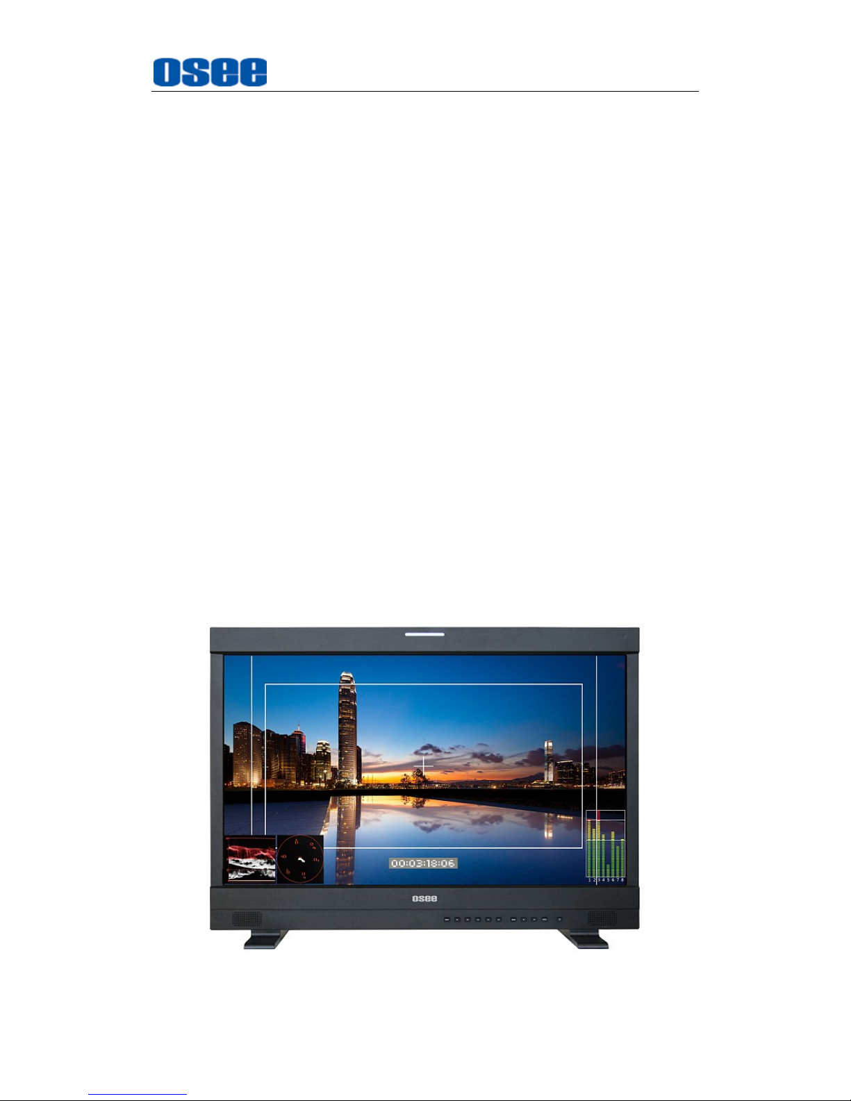
Figure 1 A Diagram of XCM-250
Page 8

Overview
2
Features
3D-LUT color calibration technology plus 12bit image processing
Having multi format input including 3G/SD/HD-SDI, 2K
Adopting full HD, wide viewing angle AMOLED panel
Proprietary algorithms provide advanced progressive/de-interlacing
technology
Various display mode: PBP, PIP, wipe and blending
Analytics waveform/vector scope, audio metering bar, TC, IMD and CC
Preset and USER defined color temperature, varied scan modes,
flexibility in marker setting, Blue Only/Monochrome mode
Color gamut adjustment, and various color spaces: EBU, SMPTE-C,
ITU-709, D-CINE
Focus assistant function and luma zoom check function
Functionality
MARKER, Time Code, MET display
Page 9
Safety
3
Chapter 2 Safety
FCC Caution:
Any Changes or modifications not expressly approved by the party responsible
for compliance could void the user's authority to operate the equipment.
This device complies with part 15 of the FCC Rules.
Operation is subject to the following two conditions: (1) This device may not
cause harmful interference, and (2) this device must accept any interference
received, including interference that may cause undesired operation.
Note: This equipment has been tested and found to comply with the limits for a
Class B digital device, pursuant to part 15 of the FCC Rules. These limits are
designed to provide reasonable protection against harmful interference in a
residential installation. This equipment generates uses and can radiate radio
frequency energy and, if not installed and used in accordance with the
instructions, may cause harmful interference to radio communications.
However, there is no guarantee that interference will not occur in a particular
installation. If this equipment does cause harmful interference to radio or
television reception, which can be determined by turning the equipment off and
on, the user is encouraged to try to correct the interference by one or more of
the following measures:
Reorient or relocate the receiving antenna.
Increase the separation between the equipment and receiver.
Connect the equipment into an outlet on a circuit different from that to which
the receiver is connected.
Consult the dealer or an experienced radio/TV technician for help.
Page 10

Safety
4
Warnings:
Read, keep and follow all of these instructions for your safety. Heed all
warnings.
Device
Install in accordance with the manufacturer's instructions.
If the brightness is adjusted to the minimum, then it might be hard to
see the display screen.
Refer all servicing to qualified service personnel. Servicing will be
required under all of the following conditions:
The unit has been exposed to rain or moisture.
Liquid had been spilled or objects have fallen onto the unit.
The unit has been damaged in any way, such as when the
power-supply cord or plug is damaged.
The unit does not operate normally, or has been dropped.
Clean only with dry cloth.
Only use attachments/accessories specified by the manufacturer.
Use only with the cart, stand, tripod, bracket, or table specified by the
manufacturer, or sold with the apparatus.
When a cart is used, use caution when moving the cart/apparatus
combination to avoid injury from tip-over.
To avoid electrical shock, do not open the cabinet. Refer servicing to
qualified personnel only.
This apparatus must be earthed.
The optional accessories are subject to change without.
Page 11
Safety
5
Position
Do not block any ventilation openings.
Do not use this unit near water.
Do not expose the unit to rain or moisture, to reduce the risk of fire or
electric shock.
Do not use this unit near any heat sources such as radiators, heat
registers, stoves, or other apparatus (including amplifiers) that product
heat.
The socket-outlet shall be installed near the equipment and shall be
easily accessible.
Power Supply Cord
Do not defeat the safety purpose of the polarized or grounding-type
plug.
Protect the power cord from being walked on or pinched, particularly at
plugs, convenience receptacles, and the point where they exit from the
unit.
If the power cord is damaged, turn off the power immediately. It is
dangerous to use the unit with a damaged power cord. It may cause
fire or electric shock.
Unplug this apparatus during lighting storms or when unused for long
periods of time.
Disconnect the power cord from the AC outlet by grasping the plug, not
by pulling the cord.
Be sure to connect to a power supply of the specified voltage.
Page 12
Safety
6
Precaution:
OLED PANEL
The OLED panel fitted to this unit is manufactured with high precision
technology, giving a functioning pixel ratio of at least 99.99%. Thus a
very small proportion of pixels may be “stuck”, either always off (black),
always on (red, green, or blue), or flashing. In addition, over a long
period of use, because of the physical characteristics of the organic
light-emitting diode, such “stuck” pixels may appear spontaneously.
These problems are not a malfunction.
Do not leave the screen facing the sun as it can damage the screen.
Take care when you place the unit by a window.
Do not push or scratch the monitor's screen. Do not place a heavy
object on the monitor’s screen. This may cause the screen to lose
uniformity.
The screen and the cabinet become warm during operation. This is not
a malfunction.
On Burn-in
Due to the characteristics of the material used in the OLED panel,
permanent burn-in or reduction in brightness may occur. These
problems are not a malfunction.
Images that may cause burn-in:
Masked images with aspect ratios other than 16:9.
Color bars or images that remain static for a long time.
Character or message displays that indicate settings or the
operating state.
On-screen displays such as center markers or area markers.
Page 13
Safety
7
To reduce the risk of burn-in
Turn off the character and marker displays:
Press the MENU button to turn off the character displays. To turn
off the character or marker displays of the connected equipment,
operate the connected equipment accordingly. For details, refer to
the operation manual of the connected equipment.
Turn off the power when not in use:
Turn off the power if the monitor is not to be used for a prolonged
period of time.
Warm-up time
To provide stable picture quality, turn on the power of the monitor and
leave it in this state for more than 30 minutes.
On a Long Period of Use
Due to an OLED’s panel structure and characteristics of materials in its
design, displaying static images for extended periods, or using the unit
repeatedly in a high temperature/high humidity environments may
cause image smearing, burn-in, areas of which brightness is
permanently changed, lines, or a decrease in overall brightness.
In particular, continued display of an image smaller than the monitor
screen, such as in a different aspect ratio may shorten the life of the
unit.
Avoid displaying a still image for an extended period, or using the unit
repeatedly in a high temperature/high humidity environment such an
airtight room, or around the outlet of an air conditioner.
To prevent any of the above issues, we recommend reducing
brightness slightly, and to turn off the power whenever the unit is not in
use.
Page 14
Safety
8
Handling and Maintenance of the Screen
The surface of the screen is specially coated to reduce image
reflection. Make sure to observe the following points as improper
maintenance procedures may impair the screen’s performance. In
addition, the screen is vulnerable to damage. Do not scratch or knock
against it using a hard object.
Be sure to disconnect the AC power cord from the AC outlet before
performing maintenance.
The surface of the screen is specially coated. Do not attach
adhesive objects, such as stickers, on it. And do not touch the
screen directly.
Wipe the screen surface gently with the supplied cleaning cloth or
a soft dry cloth to remove dirt.
Stubborn stains may be removed with the supplied cleaning cloth,
or a soft cloth slightly dampened with a mild detergent solution.
The screen may become scratched if the cleaning cloth is dusty.
Never use strong solvents such as alcohol, benzene, thinner,
acidic or alkaline detergent, detergent with abrasives, or chemical
wipe as these may damage the screen.
Use a blower to remove dust from the screen surface.
On Dew Condensation
If the unit is suddenly taken from a cold to a warm location, or if
ambient temperature suddenly rises, moisture may form on the outer
surface of the unit and/or inside of the unit. This is known as
condensation. If condensation occurs, turn off the unit and wait until
the condensation clears before operating the unit. Operating the unit
while condensation is present may damage the unit.
Page 15

Safety
9
Always verify that the unit is operating properly before use.
OSEE will not be liable for damages of any kind including, but not
limited to, compensation or reimbursement on account of the loss of
present or prospective profits due to failure of this unit, either during
the warranty period or after expiration of the warranty, or for any other
reason whatsoever.
OSEE will not be liable for claims of any kind made by user of this unit
or made by third parties.
OSEE will not be liable for the termination or discontinuation of any
services related to this unit that may result due to circumstances of any
kind.
OSEE will not be liable for damages of any kind resulting from a failure
to implement proper security measures. On transmission devices,
unavoidable data leaks resulting from transmission specifications, or
security problems of any kind.
Page 16

10
Page 17
Unpack and Installation
11
Chapter 3 Unpack and Installation
Unpack:
When unpacking the components of XCM-250 monitor, please verify that none
of the components listed in Table 3.1 are damaged or lack. If there is any
missing, contact your distributors, Beijing OSEE Technology Co., Ltd., or
OSEE Americas, Ltd. for it.
Table 3-1 Packing List
No.
Item
Quantity
1
Device
1
2
Pedestal with screws
1
3
Power cord
1
4
adapter
1
5
User manual
1
6
warranty card
1
7
Certificate card
1
Installation:
1. Prepare for installation
Please follow the procedures below before installing XCM-250:
Check the equipment for any invisible damage that may have occurred
during transit.
Confirm all the items listed on the packing list have been received.
Remove all the packing material including electrostatic-resistant
packing.
Retain these packing materials for future use.
2. Mount a XCM-250 in your desired location of a standard rack.
Adequate ventilation is required when installed to prevent possible
damage to the XCM-250.
3. Connect required cables for signal input and output. For BNC
connections use 75Ω rated connectors.
4. Connect 24V6.67ADC power source using the included power cord.
5. Connect the power cord to the power interface.
Page 18

Unpack and Installation
12
6. Fasten the power protect accessory.
7. As a final step, turn on the power switch on the rear panel to power
on the device, and press POWER button located on the front panel
to start up the screen.
The pedestal and the monitor are packaged separately.
Connect a standard signal lines to the corresponding input port. All BNC
connector impedance must be 75Ω.
Please use the power adapter supplied to avoid unnecessary trouble.
Use the power adapter and cord to connect single-phase three-wire AC
power or following the local power supply conditions. Make sure the power
cord grounding well.
The factory default value for IP address is 192.168.1.86.
.
Page 19
XCM-250 Features
13
Chapter 4 XCM-250 Features
This chapter describes the features of XCM-250 monitor. The features of
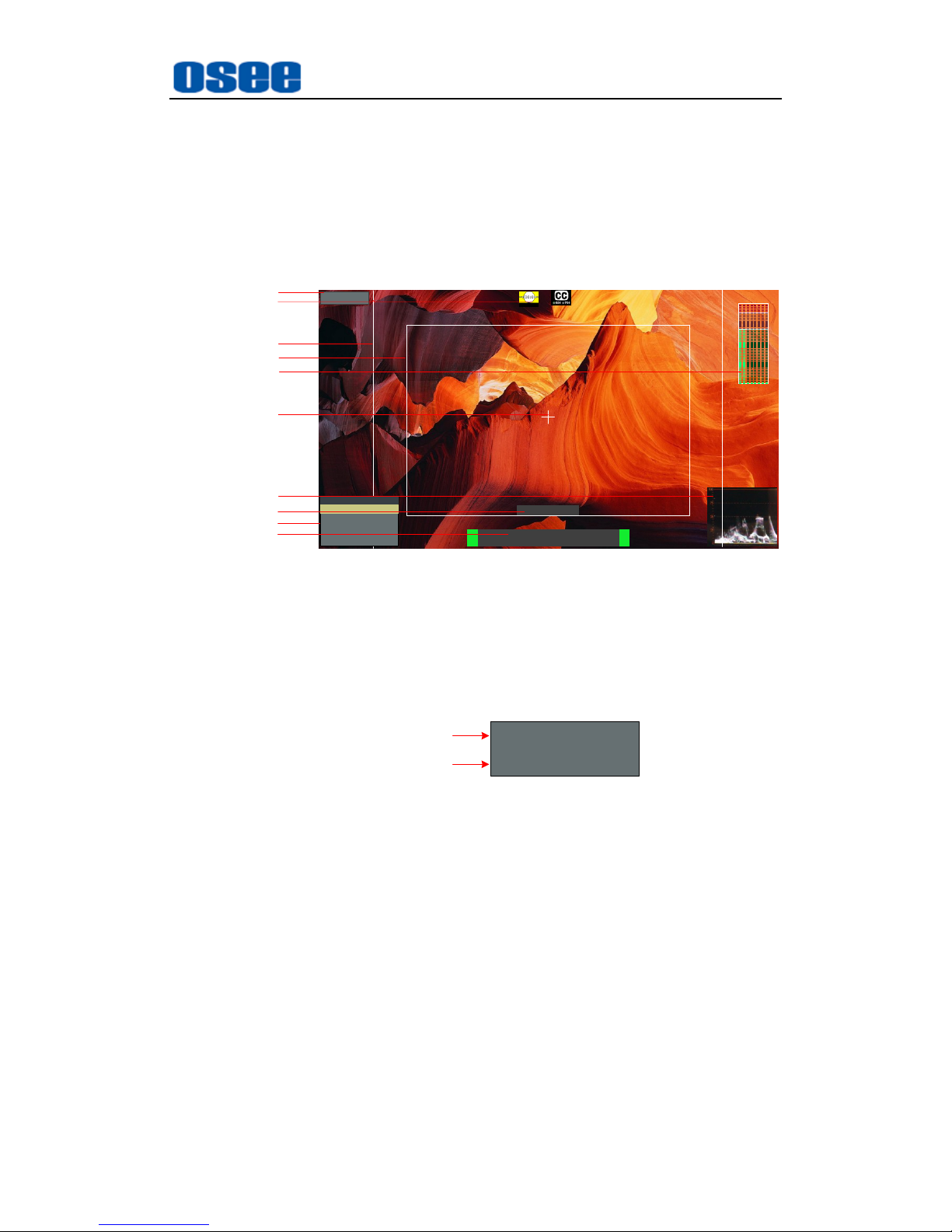
XCM-250monitor are as shown in Figure 4-1 after installed and powered on:
SDI1
1080I59.94
IMD
--:--:--:--
1 2 3 4 5 6 7 8
Status Information
Audio Meter
Center Marker
IMD
IMD
Timecode
Safe Marker
Area Marker
Adjust Menu
Wave Form
AFD CC
F1 NORMALSCAN
F2 OFFNATIVE
FUNCTION
F3 4:3ASPECT
F4
MAIN
WIN SELECT
F5 OFF
PBP
Figure 4-1 Features of XCM-250 Monitor
1. Status Information
It is displayed in the top left corner of the screen, and includes the input
channel and signal format. You can define it in DISPLAY menu.
SDI1
1080I59.94
Source
Signal Format
2. Waveform and Vector
This is effective only for SDI signal. The waveform and vector of the
input signal are configurable in the MAIN Menu.
3. Area Marker
It is used to mark different area of the image. You can set whether to
display it or not and their displaying mode in MARKER menu.
4. Safe Marker
It is used to mark different area of the image. You can set whether to
display it or not and their displaying mode in MARKER menu
5. Center Marker
It is displayed in the center of the screen, and marks the center of the
Page 20
XCM-250 Features
14
image. You can set whether to display it or not in MARKER menu.
6. Audio Meter
It is displayed for audio monitoring. You can set its groups, direction,
position and mode in AUDIO menu.
7. Timecode
It is displayed at the bottom of the image, the format is HH:MM:SS:FF, if
there is no timecode available, the monitor will display --:--:--:--.
8. IMD
The IMD text displays at the bottom of the screen, the length can’t
exceed 16 characters, and you can choose letter, number or other
character for it.
9. AFD/CC
AFD and CC information will display at the top center of the screen as
an icon.
10. MUTE
The icon for MUTE is . When it is mute, this icon displays at the
bottom right position of the screen. You can set this function in function
key.
The
Status Information
usually displays as the following situations:
"UNKNOW” appears if an unsupported signal is input.
“NO SIGNAL” appears if no signal is input.
The signal is normal, for example: 1080i59.94, NTSC, 1280X1024,
etc.
The
Status Information
for the main picture displays at the top left corner
of the screen, and the
Status Information
for the slave picture displays at
the top right corner of the screen.
The AFD information displays at the top center of the screen and can be
selected for permanent or temporary presence.
Page 21
XCM-250 Features
15
4.1 Front Panel Features
4.1.1 Arrangement of Front Panel
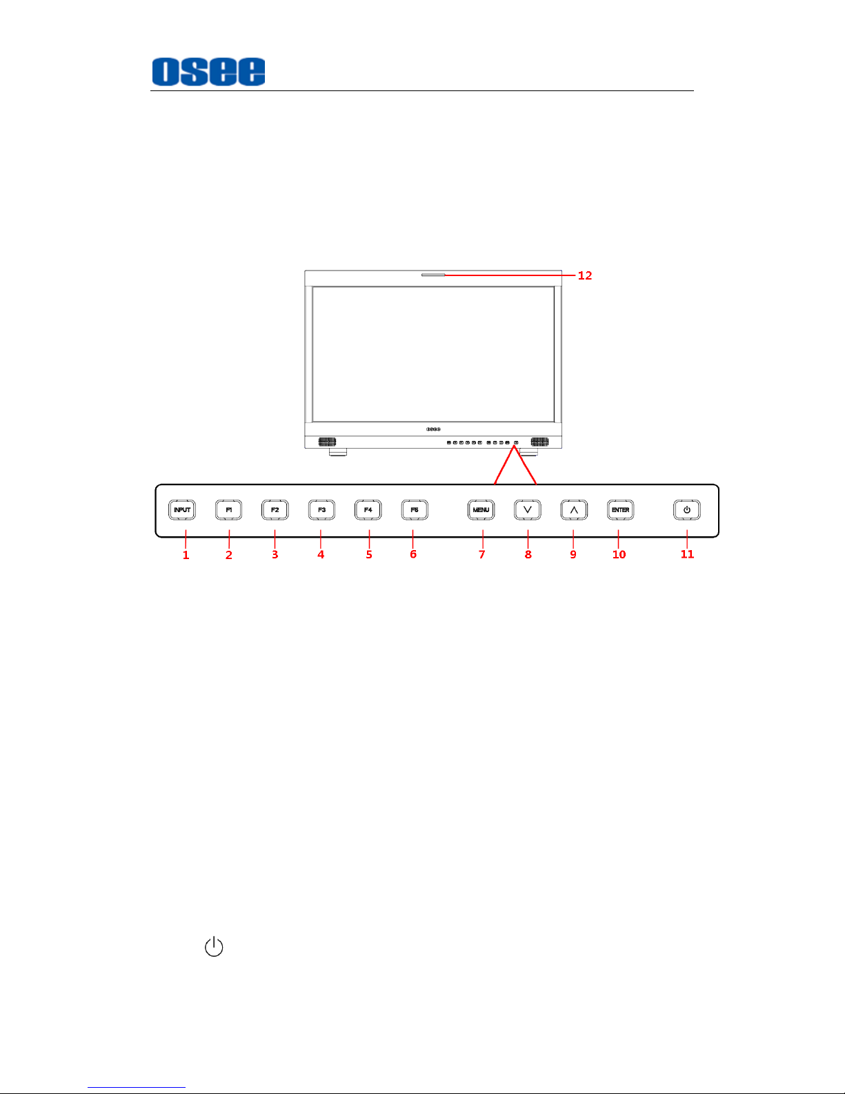
There are a series of buttons at the bottom of the screen, and these
buttons are used to control the screen menu items.
Figure 4.1-1 the Buttons in Front Panel
As shown in Figure 4.1-1 the buttons are as follows:
1. INPUT
2. F1
3. F2
4. F3
5. F4
6. F5
7. MENU
8. ∧(UP)
9. ∨(DOWN)
10. ENTER
11. (POWER)
12. TALLY: TALLY indicator(LED TALLY)
Page 22
XCM-250 Features
16
All of these buttons have indicators, the color of the indicator is different
according to the button status, as shown in Table 4.1-1.
Table 4.1-1 The Relationship of Buttons Status and Their Indicators
Button Name
Indicator Status
Description
POWER
Red
Device is in standby status(The
AUTO
STANDBY
function is OFF)
Switching Flash
(Red-GreenYellow-White)
POWER indicator will keep flashing for 60
seconds in the switching colors before the
screen saver is activated, and then flashing
slow in red when the screen saver is started.
Red Flash
The screen saver is started, that is the
device is in screen saver mode.
Green
The device is in normal operation mode, and
the input signal is connected.
Green Flash
The device is in normal operation mode, and
the input signal is disconnected.
Yellow
The device is in AUTO STANDBY mode
(make sure the
AUTO STANDBY
mode is
set to ON).
MENU/UP
/DOWN/ENTER
White
Press these buttons to activate them, and
the indicators are lighted in white; then, the
indicators will be off with no operations for
more than 10 seconds.
F1~F5
White
Press these buttons to activate them, and
the indicators are lighted in white; then, the
indicators will be off with no operations for
more than 10 seconds.
Green
The indicator will light in green when its
function is assigned as the special value as
shown in Table 5.1-14.
INPUT
White
Press these buttons to activate them, and
the indicators are lighted in white; then, the
indicators will be off with no operations for
more than 10 seconds.
Page 23
XCM-250 Features
17
The monitor will be in Auto Standby mode under the following conditions:
AUTO STANDBY
mode is set to ON in
CONFIG
menu, and the
POWER switch on the rear panel is turned on.
Then, when the signal is disconnected or the monitor is detecting
no input signal for more than 10 seconds, the monitor will enter
into
AUTO STANDBY
mode.
4.1.2 Operation of Front Panel
The functionality and usage of the buttons at the front panel are as
follows:
1. INPUT
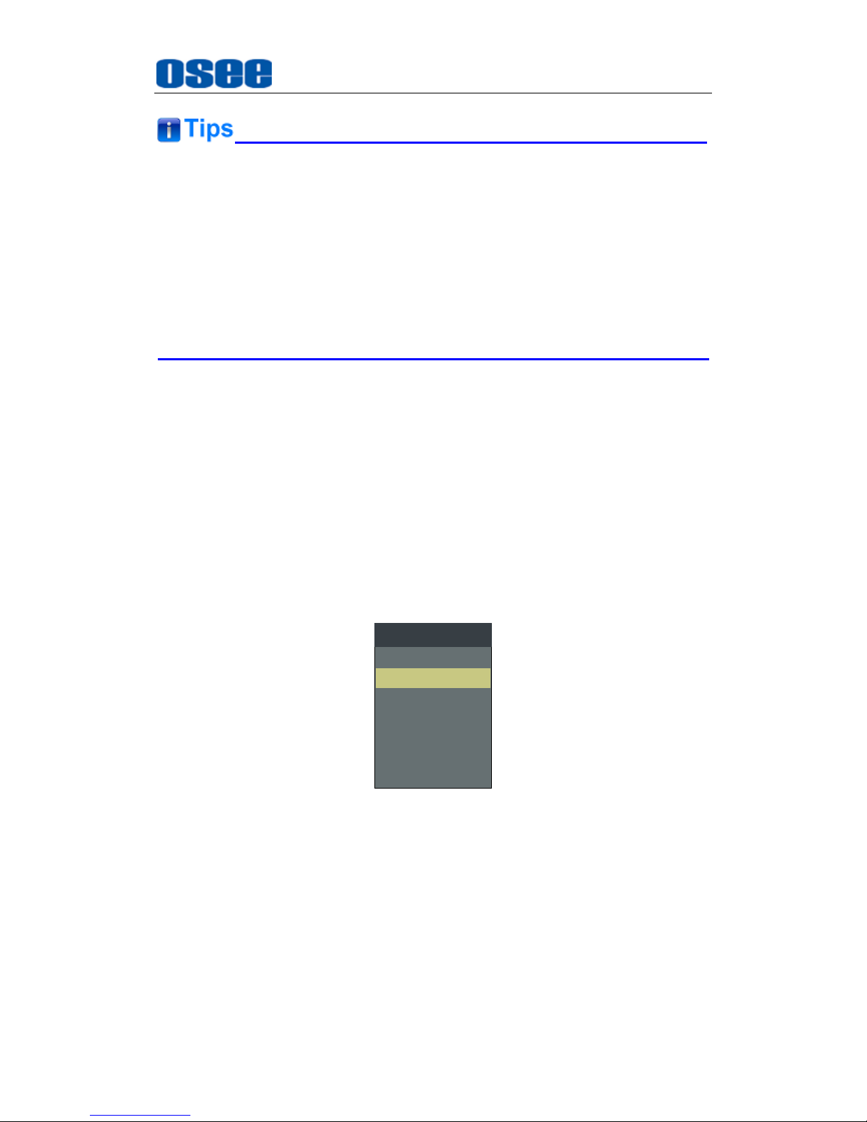
Select the input signal. Press this button to display the input source menu
at the right top corner of the screen, as shown in Figure 4.1-2. Use it to
select an input signal source, press it again to toggle among these input
signal items, or after the input source menu displayed, use the UP/DOWN
button to toggle among these input signal items.
SDI1
LINE1(CVBS)
LINE2(CVBS)
LINE2(Y/C)
SOURCE
SDI2
LINE2(YPBPR)
HDMI
Figure 4.1-2 Source Menu
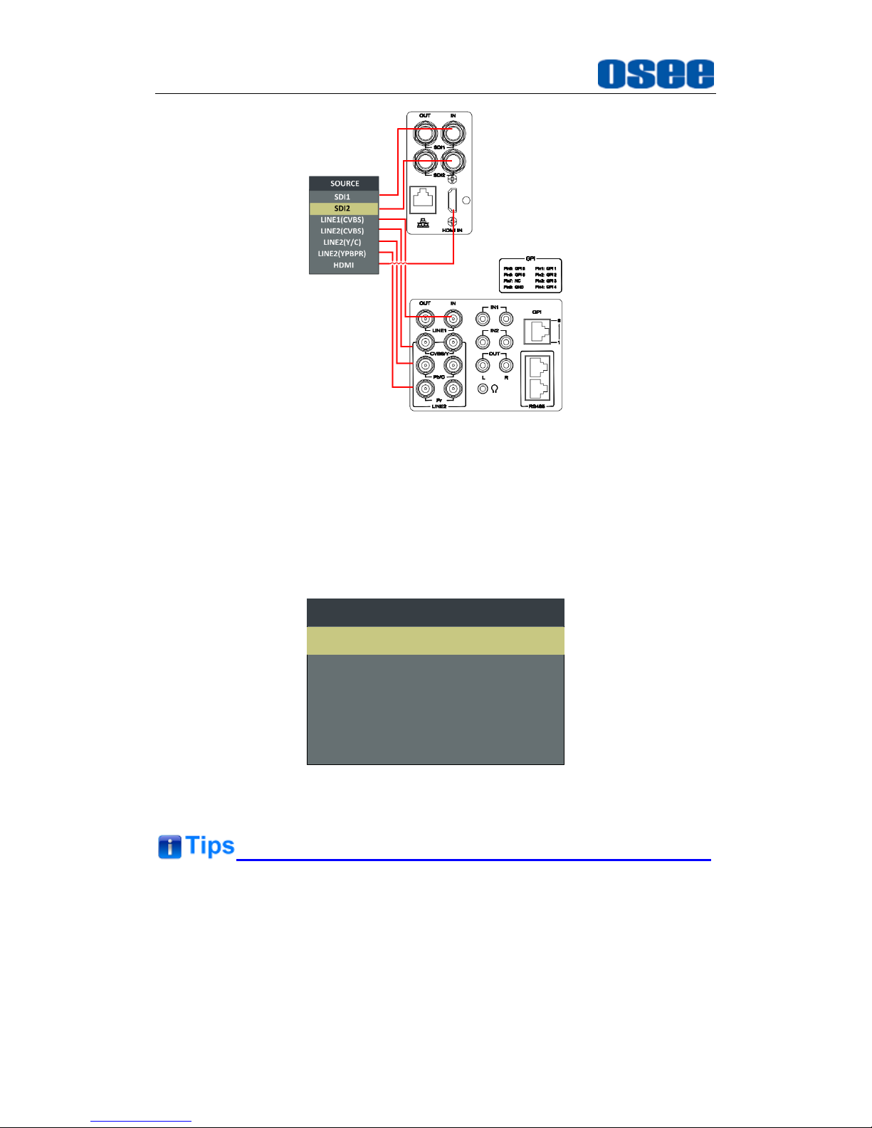
The one-to-one correspondence between the signals in the source menu
list and the interfaces in the back panel are shown in Figure 4.1-3:
Page 24
XCM-250 Features
18
Figure 4.1-3 Correspondence between Source Menu and Interface
2. F1
User defined FUNCTION button.
OPERATION:
Press F1 to display the function menu list in the center
of the screen, as shown in Figure 4.1-4. Toggle F1 button to change
the value related to this function.
F1 NORMALSCAN
F2 OFFNATIVE
FUNCTION
F3 4:3ASPECT
F4 MAINWIN SELECT
F5 OFFPBP
Figure 4.1-4 Function Menu List
After you have loaded the function menu list, it will be closed automatically
if you do nothing operation with it in 10s.
The current function value that can be modified will be indicated in highlight
yellow.
Page 25
XCM-250 Features
19
Use
FUNCTION KEY
menu to assign F1~F5 with the following commands:
SCAN, NATIVE, ASPECT, BLUE ONLY, MONO, MARKER, H/V DELAY,
AUDIO METER, FAST MODE, TC, IMD, MUTE, PBP, CC, FREEZE, WIN
SELECT, FOCUS ASSIST, LUMA ZOOM CHECK, UNDEF. Refer to "5.1.9
FUNCTION KEY Menu" for the details.
3. F2
It is used to activate to F2 function button. The operation is as the same as
F1's.
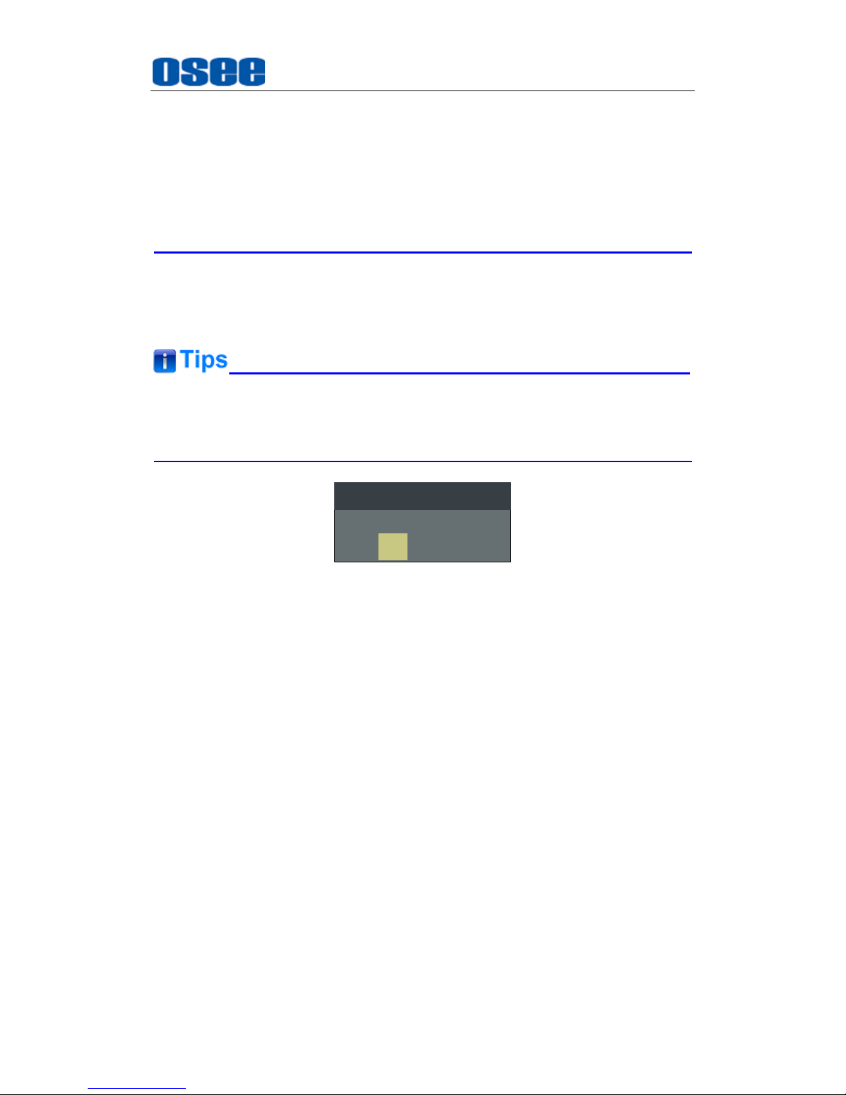
Press and hold the
INPUT+F2
button for 3s can reset the menu settings to
factory originals, as shown in Figure 4.1-5.
Factory Reset Now?
No
Yes
FACTORY RESET
Figure 4.1-5 Reset Menu List
4. F3
It is used to activate to F3 function button. The operation is as the same as
F1's.
5. F4
It is used to activate to F4 function button. The operation is as the same as
F1's.
6. F5
It is used to activate to F5 function button. The operation is as the same as
F1's.
7. MENU
Used to display or set the on-screen menu.
Pressing
MENU
step back to the higher level menu
Pressing
MENU
will cancel the Main menu
Use the MENU, ∧(UP), ∨(DOWN) and ENTER buttons to set the menu
items, refer to “5.2 Menu Settings” for detail about the main menu
Page 26
XCM-250 Features
20
operations.
8. UP
It is UP button when working with
MENU
. Toggle this button to select the
next item or increase the number.
9. DOWN
It is
DOWN
button when working with
MENU
. Toggle this button to select
the next item or decrease the number.
10. ENTER
This button can achieve the following two situations:
Work with the Main MENU
: when working with the Main menu,
ENTER button achieve the following functions:
Enter into the next level menu: press
ENTER
button, you will enter
into the menu item as this relationship: the Main menu list
sub-menu list sub-menu value list, the current editable object is
in yellow control icon;
Confirm the value selection: press
ENTER
button to confirm the
value selection.
Adjust Menu:
when not displaying the Main menu, press
ENTER
button to display the adjust menu list, as shown in Figure 4.1-6, toggle
among these menu items: VOLUME, BRIGHTNESS, CONTRAST,
CHROMA.
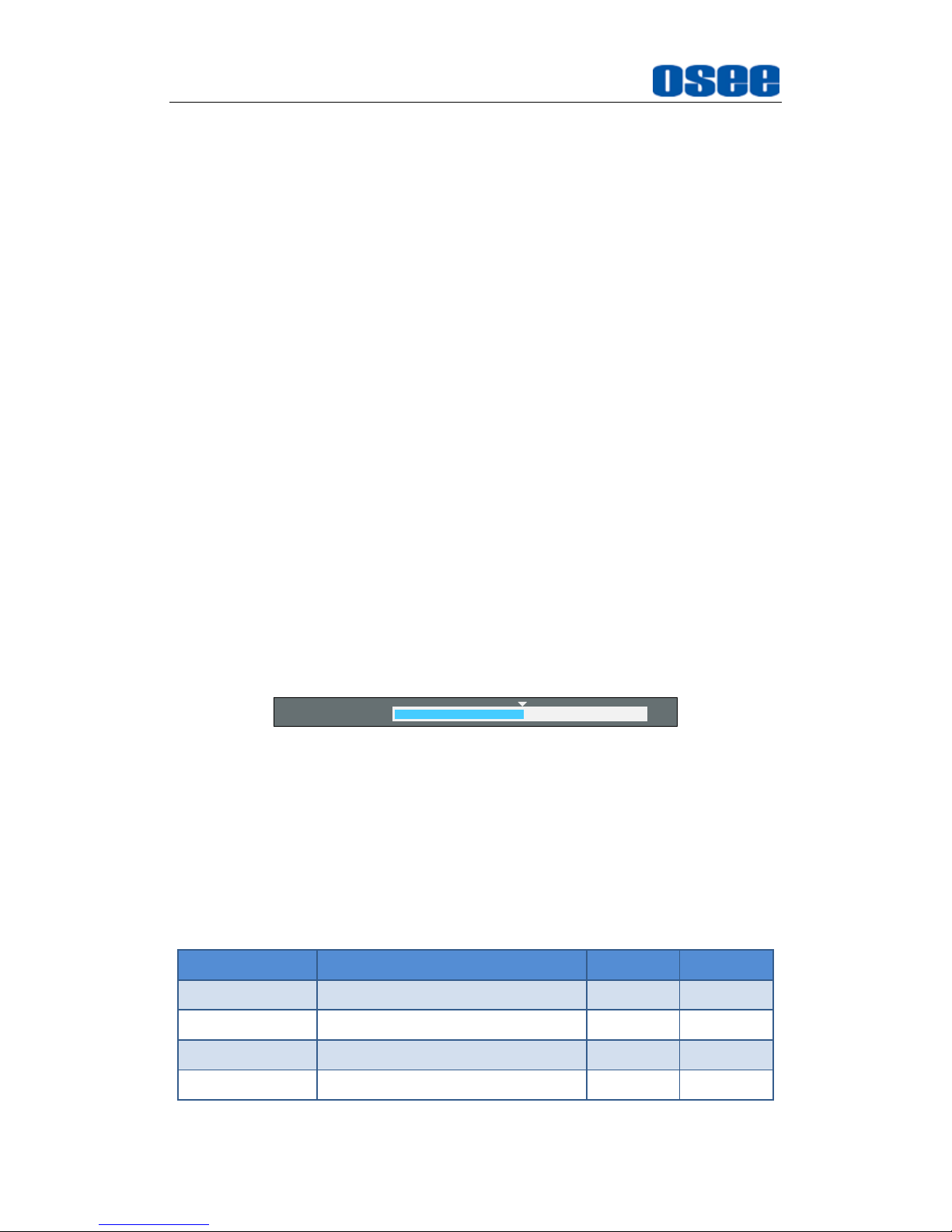
BRIGHTNESS 50
Figure 4.1-6 Adjust Menu List
After displaying the Adjust menu, press UP or
DOWN
button to adjust the
menu value, and then press
ENTER
button to confirm the value selection.
The relationship of the menu items and their range is shown in Table
4.1-2:
Table 4.1-2 The Description of Adjust Menu Items
Adjust Menu
Description
Range
Default
VOLUME
Adjust the volume
0~31dB
16
BRIGHTNESS
Adjust the image brightness
0~100
50
CONTRAST
Adjust the image contrast
0~100
50
CHROMA
Adjust the image monochroma
0~100
50
Page 27
XCM-250 Features
21
Set these parameter values in the following position: BRIGHTNESS,
CONTRAST, CHROMA.
In Adjust Menu List on screen when pressing Enter key.
In Adjust menu of network control page.
After you have loaded the adjust menu list, it will be closed automatically if
you do nothing operation with it in 10s.
The main menu, the adjust menu, the function menu and the input signal
selection list of a screen may not be shown all simultaneously.
11. Power
Used to power on or standby, and the light in the button will indicate the
status of the power.
Press
POWER
button to turn on the power when this device is in standby
mode, the indicator lights in green. Then press this button again to power
off the monitor, the indicator will be in different colors from its status, the
details are as shown in Table 4.1-1 above.
When the device is standby, cut off the power and restart the device, the
status of the device will be normal but not standby.
12. Tally
It is the physical LED Tally lamp of the monitor, and it is used to show the
status of the monitor.
4.2 Rear Panel Features
It will introduce the arrangement and the operations of the interfaces in rear of
the panel in the following.
Page 28
XCM-250 Features
22
4.2.1 Arrangement of Rear Panel
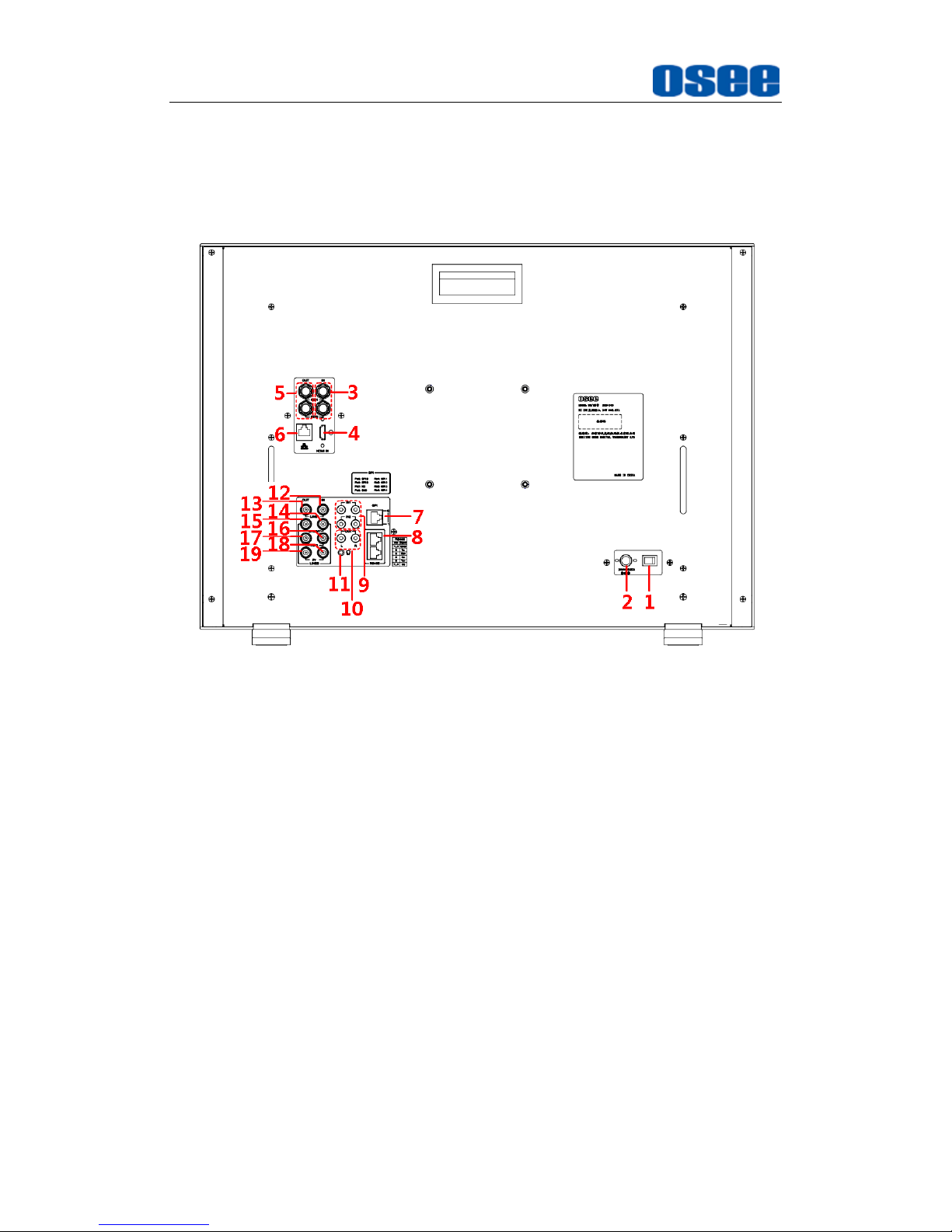
As shown in Figure 4.2-1, there are various input and output interfaces at
the rear panel of XCM-250 monitor.
Figure 4.2-1 The Rear Panel of XCM-250 Monitor
The interfaces numbered from 1 to 8 in red dotted rectangle are described
as follows:
1. Power Switch
2. Power Input
3. Video Input: SDI1 IN, SDI2 IN
4. HDMI Input
5. Video Output: SDI1 OUT, SDI2 OUT
6. Ethernet
7. GPI interface
8. RS485 In/Out
9. Audio Input
10. Audio Output
11. Headphone Output Connector (3.5mm stereo Jack)
Page 29
XCM-250 Features
23
12. Video Input: LINE1 IN
13. Video Output: LINE1 OUT
14. Video Input: LINE2(CVBS/Y) IN, feed the composited LINE2, and
component Y signals.
15. Video Output: LINE2(CVBS/Y) OUT, output the composited LINE2,
and component Y signals.
16. Video Input: LINE2(Pb/C) IN, feed the component Pb, and
component C signals.
17. Video Output: LINE2(Pb/C) OUT, output the component Pb, and
component C signals.
18. Video Input: LINE2(Pr) IN, feed the component Pr signal.
19. Video Output: LINE2(Pr) OUT, output the component Pr signal.
4.2.2 Operations of Rear Panel
The details of these interfaces at the rear panel are described as follows:
1. Power Switch
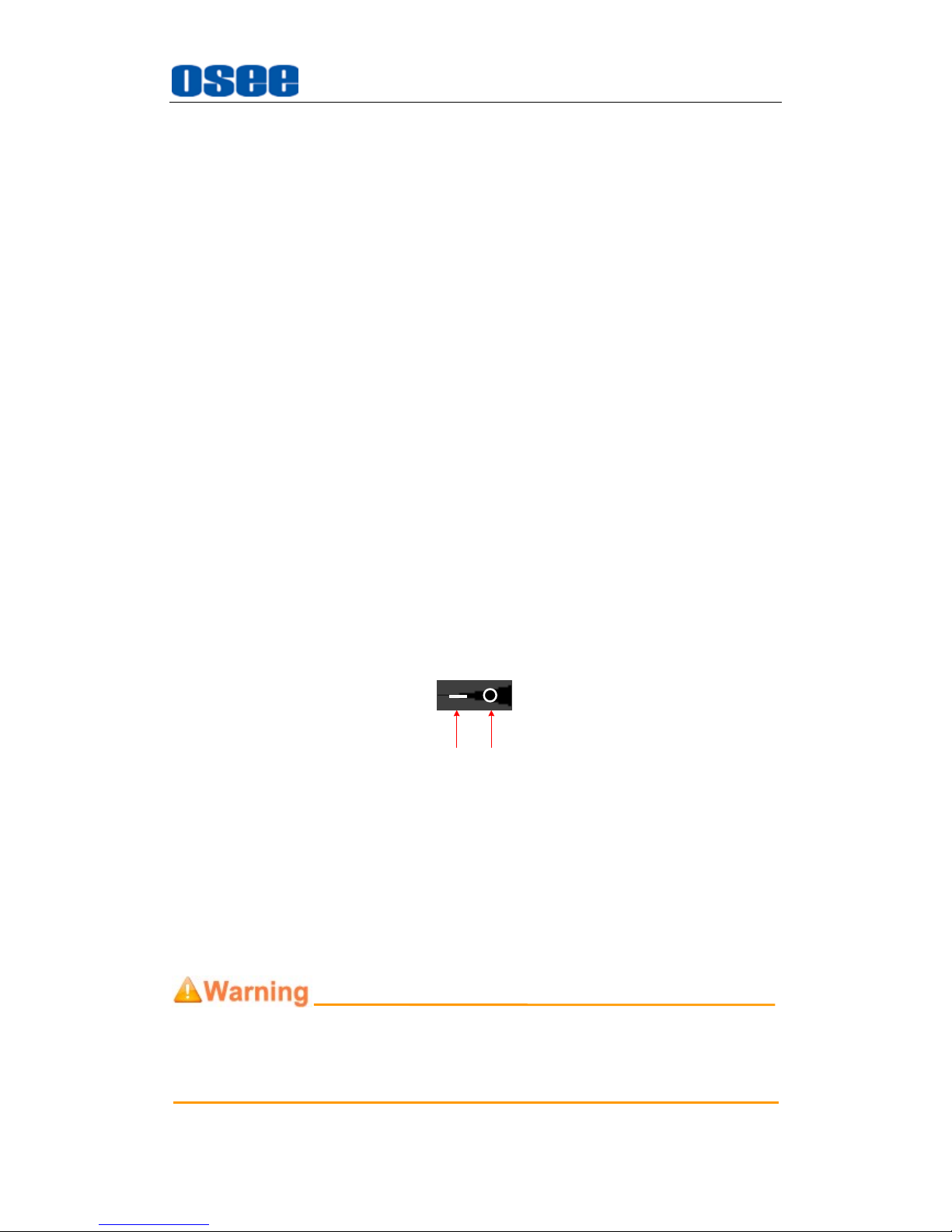
It provides one power switch to switch on or switch off. As shown in
Figure 4.2-2, push the button to the direction “-” to switch on the power,
or push the button to the direction “” to switch off the power.
ON OFF
Figure 4.2-2 Power Switch
2. Power Input
It provides one power input interface, the specification is 24V6.67ADC.
The corresponding indicator is at the front panel. If the light is green, the
monitor is powered on, and if the light is off, the monitor has not put
through the power.
Only use the adapter and the power cord specified by the manufacture for
your safety!
Page 30
XCM-250 Features
24
3. Video Input Interface (BNC)
It provides two SDI input interfaces, one is labeled as SDI1 IN, and the
other is SDI2 IN.
4. HDMI
It provides one HDMI input interface, HDMI Type-A connector with a
fastener compatible with DVI-D.
5. Video Output Interface (BNC)
It provides two SDI output interfaces. One is labeled as SDI1 OUT, the
other is SDI2 OUT, active loop.
6. Ethernet (RJ-45)
It provides one 10/100M Ethernet connector. It is used to connect with a
computer to modify the network settings.
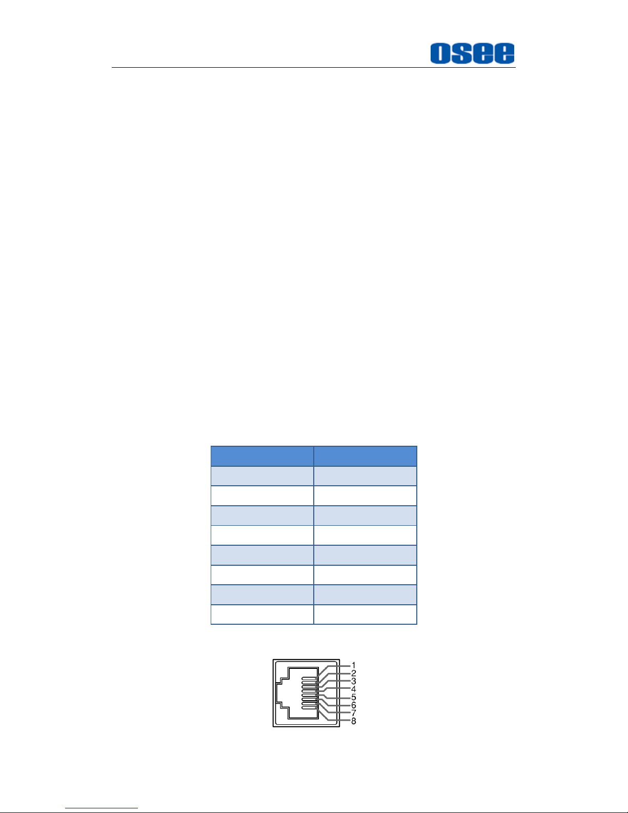
7. GPI(RJ-45)
It assigns a function to each pin of the GPI interface to realize a remote
control mode. Define a function to the GPI pin. Refer to “5.1.10 GPI
Menu” for the definition of the pins and the functions.
The relationship of the pins of GPI interface and its channel value is
shown in Table 4.2-1.
Table 4.2-1 The Relationship of GPI Pins and Channel Values
Pin No.
Channel Value
Pin 1
GPI1
Pin 2
GPI2
Pin 3
GPI3
Pin 4
GPI4
Pin 5
GPI5
Pin 6
GPI6
Pin 7
NC
Pin 8
GND
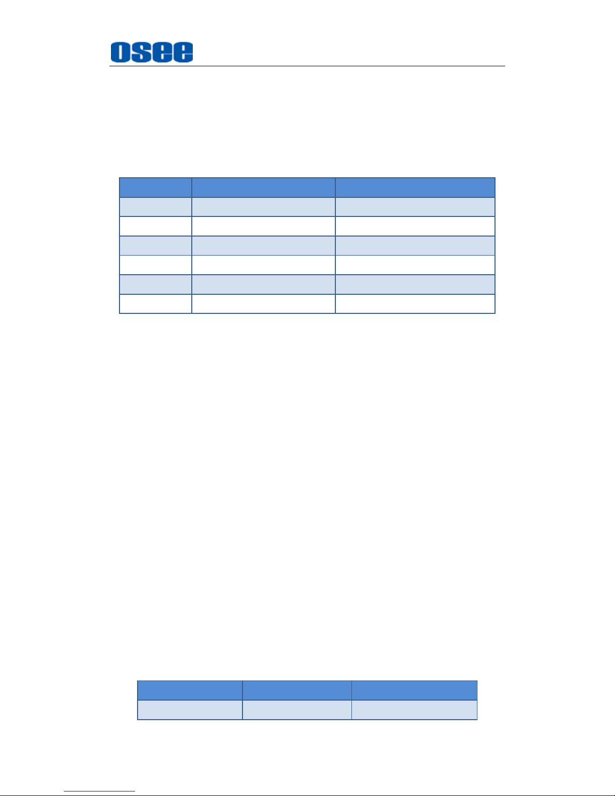
8. IN/ OUT RS485 Interface (RJ-45)
Page 31
XCM-250 Features
25
Support for dynamic IMD and updating the new firmware.
The Comparison of Pins and Input/output connectors for RS485 is
shown as in Table 4.2-2:
Table 4.2-2 The Comparison of Pins and Input/output connectors for
RS485
PIN No.
RS485 IN Terminal Signal
RS485 OUT Terminal Signal
1,2
GND
GND
3
Tx-
Tx- 4 Rx+
Rx+
5
Rx-
Rx-
6
Tx+
Tx+
7,8
NC
NC
9. Audio Input interface
It provides four audio(2 pairs) input interfaces, 5dBu, impedance≥47K,
RCA connector.
10. Audio Output interface
It provides two audio output interfaces, 5dBu, impedance≤500Ω, RCA
connector.
11. Headphone jack
It provides one interface for the headphone at the position of Ω icon.
The audio signal which is selected by the input button is output in stereo
sound.
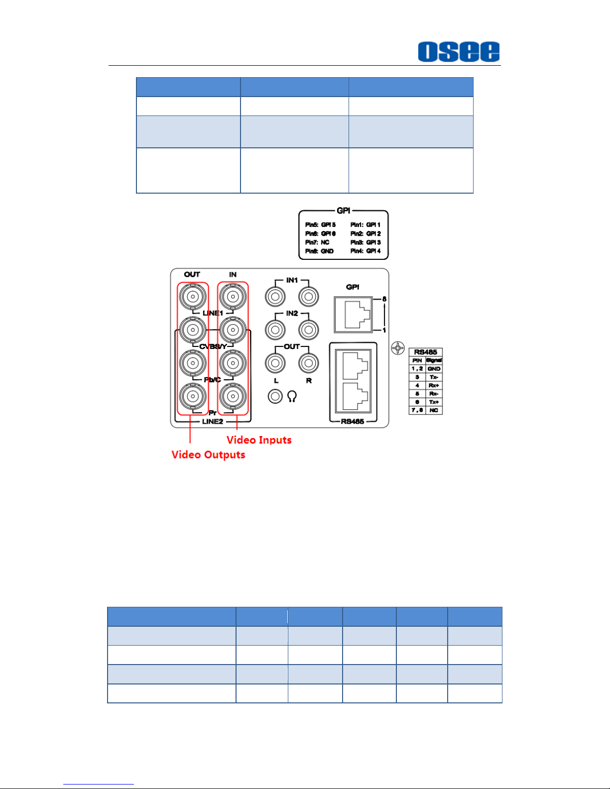
12. Video Input/Output Interface (BNC)
It provides two pairs of Composited Video input/output interfaces(LINE1,
LINE2), and a group of component signals(YPbPr, Y/C), the Y/C signal
is also called as S-Video. It will transmit the corresponding component
signal to different signal type according to the selection of the signal
source.
As shown in Figure 4.2-3, the relationship of the signal sources and the
interfaces are shown as in Table 4.2-3:
Table 4.2-3 The Relationship of the Signal Sources and Input/output
Interfaces
Signal Source
Video Input
Video Output
LINE1
LINE1 IN
LINE1 OUT
Page 32
XCM-250 Features
26
Signal Source
Video Input
Video Output
LINE2(CVBS)
LINE2(CVBS/Y) IN
LINE2(CVBS/Y) OUT
LINE2(Y/C)
LINE2(CVBS/Y) IN
LINE2(Pb/C) IN
LINE2(CVBS/Y) OUT
LINE2(Pb/C) OUT
LINE2(YPBPR)
LINE2(CVBS/Y) IN
LINE2(Pb/C) IN
LINE2(Pr) IN
LINE2(CVBS/Y) OUT
LINE2(Pb/C) OUT
LINE2(Pr) OUT
Figure 4.2-3 Video Input/Output Interfaces
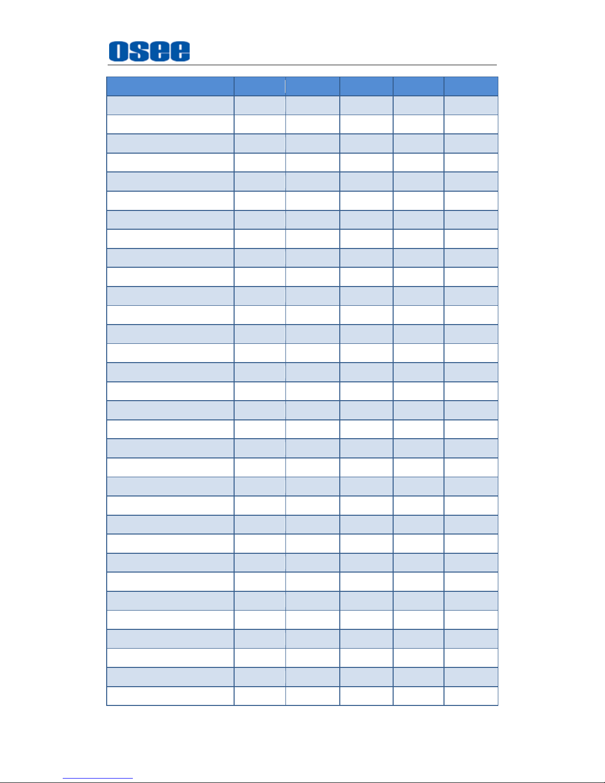
4.3 Supported Signal Format
The supported signal format for this device is as shown in Table 4.3-1:
Table 4.3-1 Supported Signal Format
SDI
VIDEO
HDMI
YC
YPBPR
PAL
NTSC
480I60/59.94
576I50
Page 33
XCM-250 Features
27
SDI
VIDEO
HDMI
YC
YPBPR
480P60/59.94
576P50
720P24/23.97
720P25
720P30/29.97
720P50
720P60/59.94
1080SF24/23.97
1035I60/59.94
1080I50
1080I60/59.94
1080P24/23.97
1080P25
1080P30/29.97
1080P50
1080P60/59.94
2048X1080PSF24/23.97
2048X1080PSF25
2048X1080PSF30/29.97
2048X1080P24/23.97
2048X1080P25
2048X1080P30/29.97
2048X1080P48/47.94
2048X1080P50
2048X1080P60/59.94
VGA(640X480)
SVGA(800X600)
XGA(1024X768)
SXGA(1280X1024)
WXGA(1360X768)
WXGA+(1440X900)
WXGA+(1400X1050)
Page 34
XCM-250 Features
28
SDI
VIDEO
HDMI
YC
YPBPR
UXGA(1600X1200)
UXGA+(1680X1050)
WUXGA(1920X1080)
WUXGA(1920X1200)
Page 35
Functionality of the Main Menu
29
Chapter 5 Functionality of the Main Menu
This chapter describes the structure and functionality of the main menu, and
introduces how to modify and customize the menu settings.
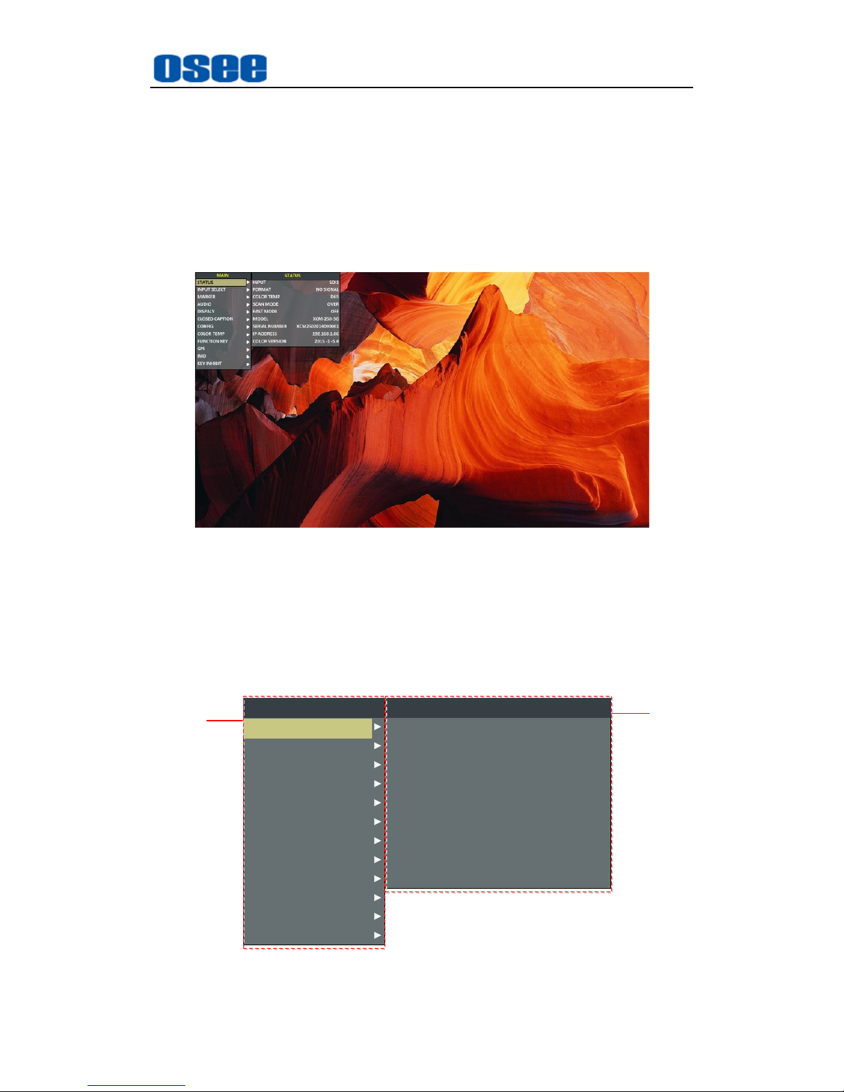
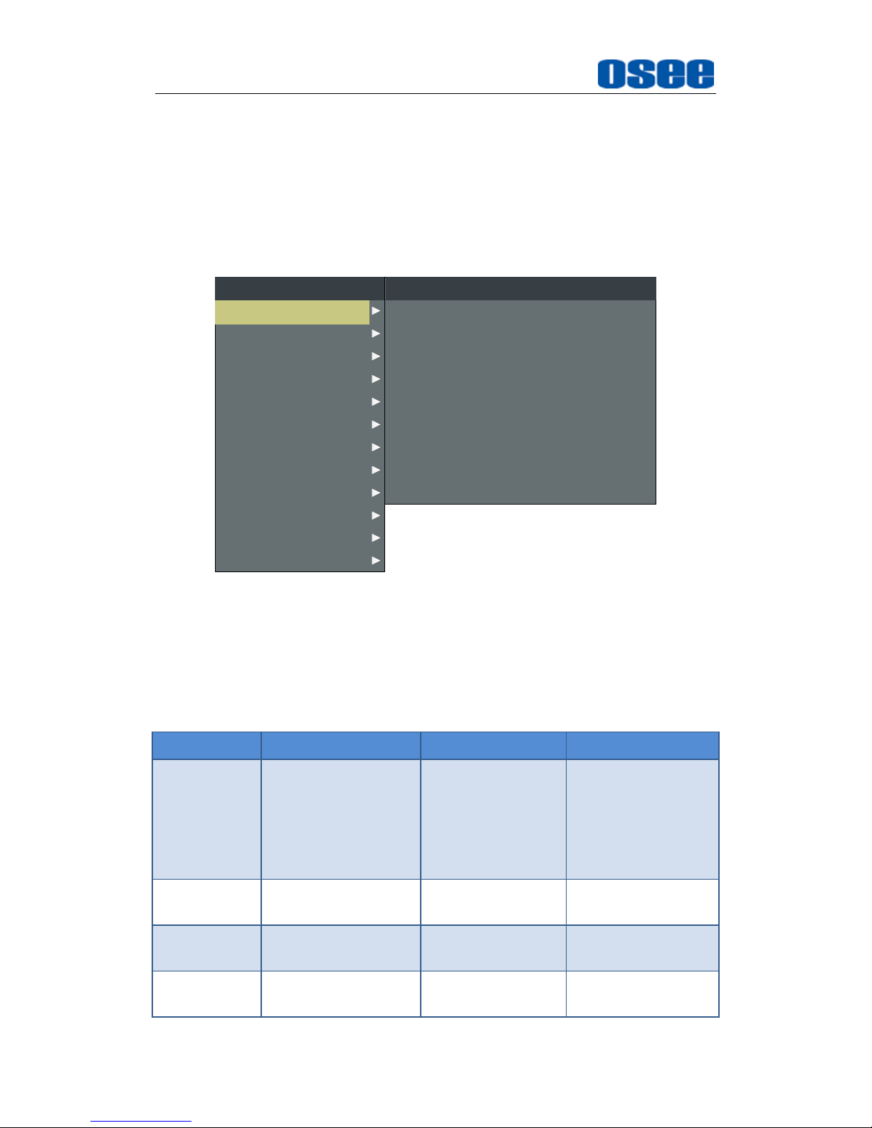
The main menu includes the following menu items, as shown in Figure5-1.
Figure 5-1 Main Menu
5.1 Main Menu
Press the MENU button at the bottom of the front panel, the main menu is
displayed at the top left corner of the screen, as shown in Figure 5.1-1:
CLOSED CAPTION
INPUT SELECT
MARKER
AUDIO
DISPALY
CONFIG
COLOR TEMP
FUNCTION KEY
GPI
MAIN
MODEL
INPUT
FORMAT
COLOR TEMP
SCAN MODE
FAST MODE
SERIAL NUMBER
IP ADDRESS
COLOR VERSION
STATUS
XCM-250-3G
SDI1
NO SIGNAL
D65
OVER
OFF
XCM2502014090001
192.168.1.86
2015 -1 -5.4
STATUS
IMD
KEY INHIBIT
1
1
2
2
Figure 5.1-1 the Structure of the Main Menu
Page 36
Functionality of the Main Menu
30
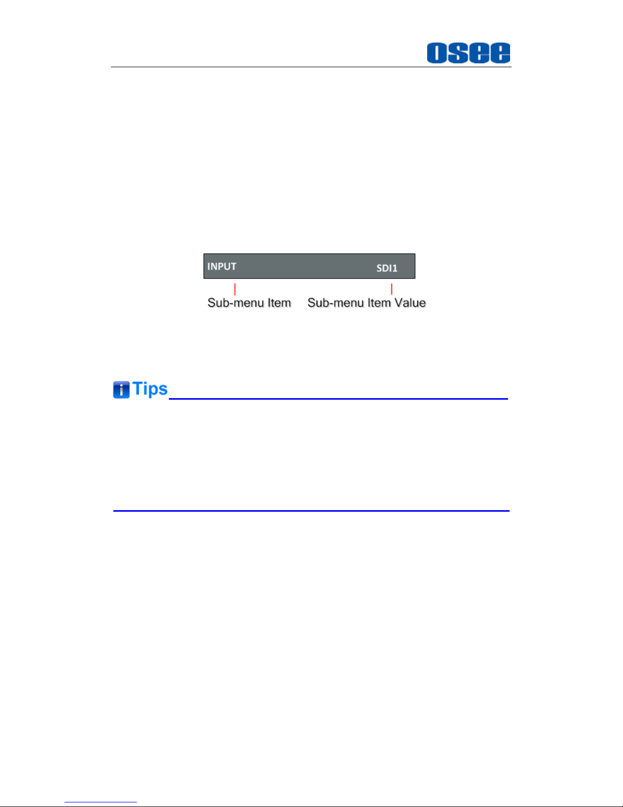
The menu interface is divided into two panes:
1. Main Menu List
It contains the title of the Main menu and several sub-menu items. The
title of this list is
MAIN
. Press UP or
DOWN
to access the corresponding
menu item.
2. Sub-menu list
As shown in Figure 5.1-2, it lists the title of the
Sub-menu
, the sub-menu
item and the value of the item. After pressing
Menu
button, press UP,
DOWN
button and
Enter
button to modify the value of the sub-menu.
Refer to “5.2 Menu Settings” for details.
Figure 5.1-2 the Sub-menu Value List
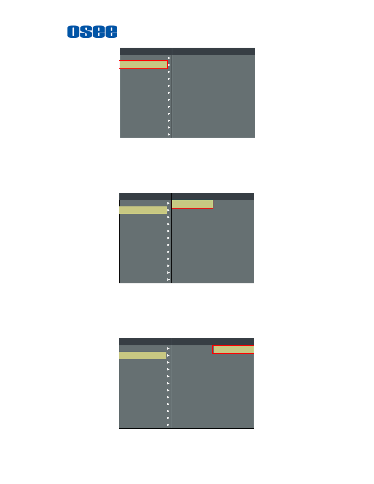
There is a yellow control icon where you select the menu or its value presently.
The sub-menu item is selected when the control icon which is in yellow
highlight is at the back of the item name.
The sub-menu item value is editable when the control icon which is in
yellow highlight is at the back of the item value.
The control icon of the main menu has the following status when in different
positions, as shown in the red rectangle of the following figures:
when in the main menu, it shows that this menu item is selected, as
shown in Figure 5.1-3:
Page 37
Functionality of the Main Menu
31
CLOSED CAPTION
MARKER
AUDIO
DISPALY
CONFIG
COLOR TEMP
FUNCTION KEY
GPI
MAIN
INPUT SELECT
STATUS
IMD
KEY INHIBIT
NTSC SETUP
SDI1
SDI2
LINE1
LINE2
HDMI
NTSC PHASE
INPUT SELECT
7.5
ON
ON
ON
CVBS
ON
0
LUMA ZOOM CHECK
FOCUS ASSIST
FOCUS LEVEL
FOCUS COLOR
LUMA ZOOM LEVEL
OFF
OFF
50
RED
50
Figure 5.1-3 A Main Menu Item Is Selected
when in the sub-menu item, it shows that this sub-menu item is
selected, and the control icon is displayed as a yellow rectangle in front
of it, as shown in Figure 5.1-4:
CLOSED CAPTION
MARKER
AUDIO
DISPALY
CONFIG
COLOR TEMP
FUNCTION KEY
GPI
MAIN
INPUT SELECT
STATUS
IMD
KEY INHIBIT
NTSC SETUP
SDI1
SDI2
LINE1
LINE2
HDMI
NTSC PHASE
INPUT SELECT
7.5
ON
ON
ON
CVBS
ON
0
LUMA ZOOM CHECK
FOCUS ASSIST
FOCUS LEVEL
FOCUS COLOR
LUMA ZOOM LEVEL
OFF
OFF
50
RED
50
Figure 5.1-4 A Sub-menu Item Is Selected
when in the sub-menu item value, it shows that this sub-menu item
value is selected, and the value is displayed in yellow, as shown in
Figure 5.1-5:
CLOSED CAPTION
MARKER
AUDIO
DISPALY
CONFIG
COLOR TEMP
FUNCTION KEY
GPI
MAIN
INPUT SELECT
STATUS
IMD
KEY INHIBIT
NTSC SETUP
SDI1
SDI2
LINE1
LINE2
HDMI
NTSC PHASE
INPUT SELECT
7.5
ON
ON
ON
CVBS
ON
0
LUMA ZOOM CHECK
FOCUS ASSIST
FOCUS LEVEL
FOCUS COLOR
LUMA ZOOM LEVEL
OFF
OFF
50
RED
50
Figure 5.1-5 A Sub-menu Item Value Is Selected
Page 38
Functionality of the Main Menu
32
The following will introduce the contents and functionality of these sub-menu
items in sorts.
5.1.1 STATUS Menu
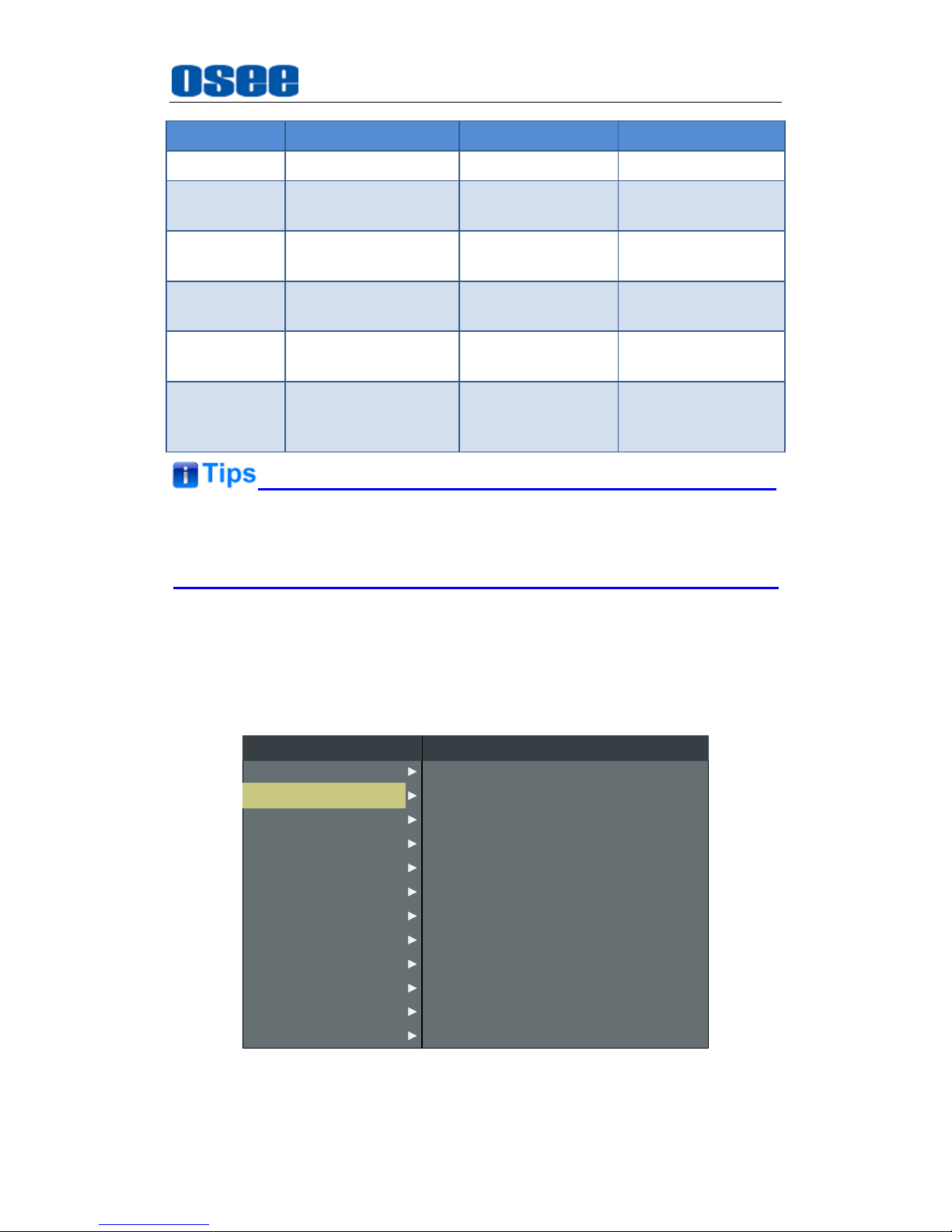
The STATUS menu items are used to describe the current status
information of the monitor, the menu items are as shown in Figure 5.1-6:
CLOSED CAPTION
INPUT SELECT
MARKER
AUDIO
DISPALY
CONFIG
COLOR TEMP
FUNCTION KEY
GPI
MAIN
MODEL
INPUT
FORMAT
COLOR TEMP
SCAN MODE
FAST MODE
SERIAL NUMBER
IP ADDRESS
COLOR VERSION
STATUS
XCM-250-3G
SDI1
NO SIGNAL
D65
OVER
OFF
XCM2502014070001
192.168.1.86
2015 -1 -5.4
STATUS
IMD
KEY INHIBIT
Figure 5.1-6 STATUS Menu
The relationship of Items, Default Value, Domain Range and Description
of the sub-item is shown in Table 5.1-1:
Table 5.1-1 The Description of STATUS Menu Items
Items
Default Value
Domain Range
Description
INPUT
SDI1
SDI1/SDI2
LINE1(CVBS)
LINE2(CVBS)
LINE2(Y/C)
LINE2(YPBPR)
HDMI
Show the Input
format.
FORMAT
NO SGINAL
--
Show the format of
the input signal.
COLOR
TEMP
D65
--
Show the color
temperature.
SCAN MODE
NORMAL
NORMAL
OVER
Show the scan
mode.
Page 39
Functionality of the Main Menu
33
Items
Default Value
Domain Range
Description
UNDER
FAST MODE
OFF
OFF/ON
Show the fast
mode.
MODEL
XCM-250-3G
--
Show the
production model.
SERIAL
NUMBER
XCM2502014090001
--
Show the serial
number.
IP ADDRESS
192.168.1.86
--
Show the IP
address.
COLOR
VERSION
2015-1-5.4
--
Show the color
version according to
its adjusted date.
The sub-menu values in
STATUS
menu can’t be modified, they are
displayed the actual status of the monitor.
5.1.2 INPUT SELECT Menu
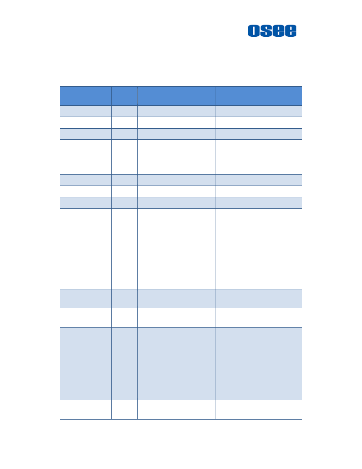
The INPUT SELECT menu items are used to set the source of the input
signals, the menu items are as shown in Figure 5.1-7:
CLOSED CAPTION
MARKER
AUDIO
DISPALY
CONFIG
COLOR TEMP
FUNCTION KEY
GPI
MAIN
INPUT SELECT
STATUS
IMD
KEY INHIBIT
NTSC SETUP
SDI1
SDI2
LINE1
LINE2
HDMI
NTSC PHASE
INPUT SELECT
7.5
ON
ON
ON
CVBS
ON
0
LUMA ZOOM CHECK
FOCUS ASSIST
FOCUS LEVEL
FOCUS COLOR
LUMA ZOOM LEVEL
OFF
OFF
50
RED
50
Figure 5.1-7 INPUT SELECT Menu
Page 40
Functionality of the Main Menu
34
The relationship of Items, Default Value, Domain Range and Description
of the sub-item is shown in Table 5.1-2:
Table 5.1-2 The Description of INPUT SELECT Menu Items
Items
Default
Value
Domain Range
Description
SDI1
ON
ON/OFF
Enable/Disable SDI1 input.
SDI2
ON
ON/OFF
Enable/Disable SDI2 input.
LINE1
ON
ON/OFF
Enable/Disable LINE1 input.
LINE2
ON
CVBS
LINE2(Y/C)
LINE2(YPBPR)
OFF
Enable/Disable LINE2 input,
and select the input source
format.
HDMI
ON
ON/OFF
Enable/Disable HDMI input.
NTSC SETUP
7.5
0/7.5
Select the NTSC mode.
NTSC PHASE
0
-50~50
Set the NTSC phase.
FOCUS ASSIST
OFF
OFF
STANDARD: An
image with
sharpened edges is
displayed.
COLOR: Displays
the intensified areas
of images with color
selected in FOCUS
COLOR.
Enable/Disable the focus
assist function, and set the
focus assist mode.
FOCUS LEVEL
50
0~100
Set the level of edge
sharpening.
FOCUS
COLOR
RED
RED/GREEN/BLUE
Set the color for the
sharpened edge.
LUMA ZOOM
CHECK
OFF
ON/OFF
Enable/Disable the luma
zoom check function that
will compare the signal
luminance with the
LUMA
ZOOM LEVEL
, and fill the
relevant image area whose
luminance is higher than the
LUMA ZOOM LEVEL
with a
zebra pattern.
LUMA ZOOM
LEVEL
50
0~100
Set the level of detecting
luminance.
Page 41
Functionality of the Main Menu
35
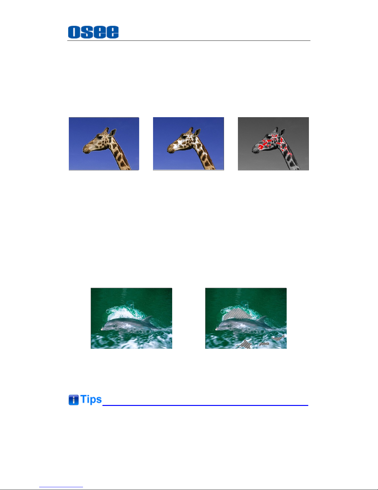
1. FOCUS ASSIST
The FOCUS ASSIST function is used to display images on the screen with
sharpened edges to help camera focus operation. The sharpened edges
are the compared area whose luminance is beyond the reference level,
and the edges are displayed in the pointed color.
For example, set the
FOCUS COLOR
as RED, and set the
FOCUS
LEVEL
as 80, the compared results are as shown Figure 5.1-8:
FOCUS ASSIST=STANDARDORIGINAL IMAGE
FOCUS ASSIST=COLOR
Figure 5.1-8 Illustration for FOCUS ASSIST Function
2. LUMA ZOOM CHECK
The LUMA ZOOM CHECK function is used to display images on the
screen with a zebra pattern to adjust the camera exposure parameter. It
will compare the signal luminance with the
LUMA ZOOM LEVEL
, and fill
the relevant image area whose luminance is higher than the
LUMA ZOOM
LEVEL
with a zebra pattern.
For example, set the
LUMA ZOOM LEVEL
as 80, the compared results
are as shown in Figure 5.1-9, the special area is filled with a zebra pattern.
LUMA ZOOM CHCEKORIGINAL IMAGE
Figure 5.1-9 Illustration for LUMA ZOOM CHECK Function
Select input source format for LINE2: For the LINE2(CVBS) interface, the
LINE2(Y/C) interface and the LINE2(YPSPR) interface share the same
group of physical interfaces, select the signal source format for LINE2
Page 42
Functionality of the Main Menu
36
according to the line connection mode. When select a signal source format
for LINE2, you can set the menu item
INPUT SELECTLINE2
as CVBS,
LINE2(Y/C) or LINE2(YPBPR), in addition, press
INPUT
button to pop up
the source list for LINE2 selection.
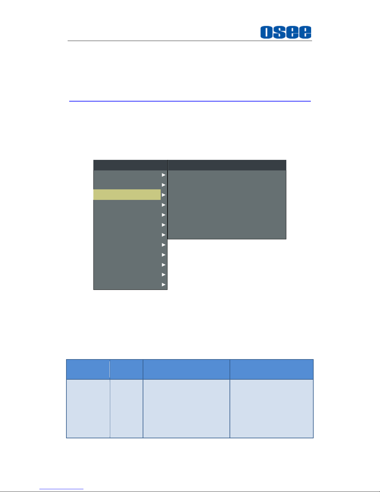
5.1.3 MARKER Menu
The MARKER menu items are used to adjust the marker parameters, the
menu items are as shown in Figure 5.1-10:
CLOSED CAPTION
AUDIO
DISPALY
CONFIG
COLOR TEMP
FUNCTION KEY
GPI
MAIN
MARKER
INPUT SELECT
STATUS
IMD
KEY INHIBIT
MARKER MAT
MARKER
AREA MARKER
CENTER MARKER
SAFETY MARKER
MARKER LEVEL
CROSS HATCH
MARKER
OFF
OFF
OFF
OFF
OFF
1
OFF
Figure 5.1-10 MARKER Menu
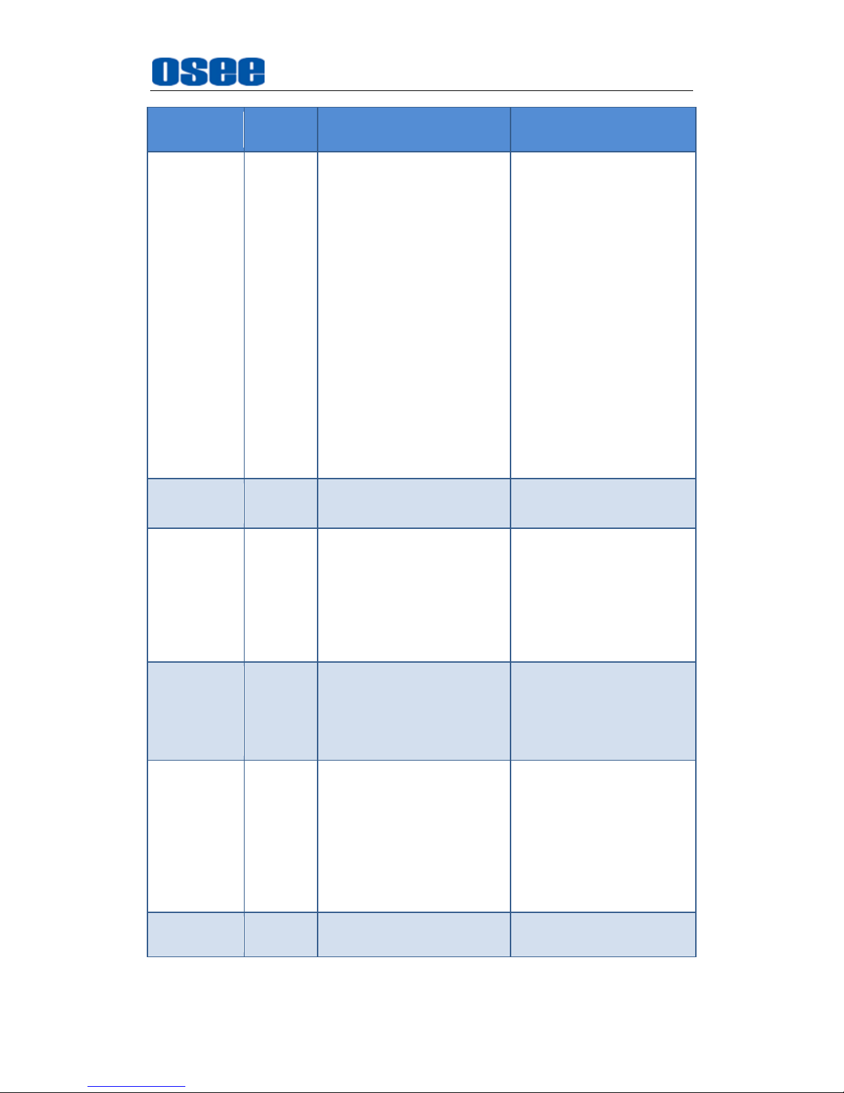
The relationship of Items, Default Value, Domain Range and Description
of the sub-item is shown in Table 5.1-3:
Table 5.1-3 The Description of MARKER Menu Items
Items
Default
Value
Domain Range
Description
MARKER
OFF
OFF/ON
Set whether to show all of
the markers.
It is the main switch for
area marker, center
marker and safety
marker.
Page 43
Functionality of the Main Menu
37
Items
Default
Value
Domain Range
Description
AREA
MARKER
OFF
when the display aspect is
16:9, images show with
the following scale:
OFF: close area
marker
4:3
15:9
14:9
13:9
1.85:1
2.35:1
when the display aspect is
4:3, images show with the
following scale:
OFF: close area
marker
16:9
Select the area marker
aspect ratio according to
the display aspect ratio.
CENTER
MARKER
OFF
OFF/ON
Set whether to show the
center marker.
SAFETY
MARKER
OFF
OFF
80%
85%
88%
90%
93%
95%
Set the safety area size
according to the aspect
ratio and scan mode.
MARKER
LEVEL
1
1: 20%
2: 50%
3: 75%
Set the luminance of
marker line, including
safety marker, center
marker, area marker and
cross hatch.
MARKER
MAT
OFF
OFF: Normal
background, use line
for area marker edge
only
HALF: 50%
Background
brightness
BLACK: all black
Set the transparency of
area marker mat which is
on the outside of the
marker display.
CROSS
HATCH
OFF
OFF/ON
Set whether to show the
cross hatch.
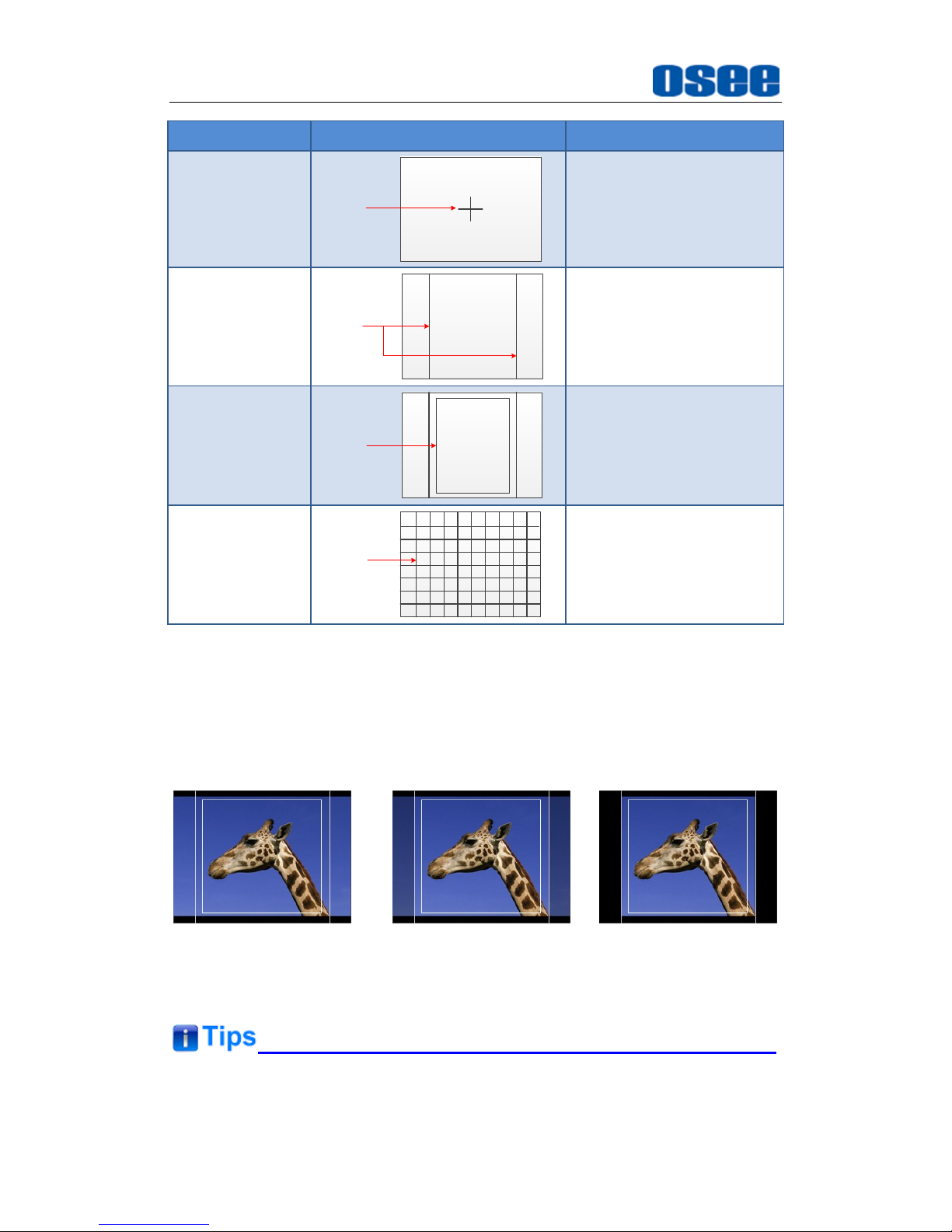
Markers
Page 44
Functionality of the Main Menu
38
Marker
Illustration
Description
CENTER
MARKER
CENTER
MARKER
This marker enables
easier checking the center
portion’s focus.
AREA MARKER
AREA
MARKER
This marker displays two
lines to identify an area
with a specified ratio.
SAFETY
MARKER
SAFETY
MARKER
This marker displays a
rectangle to identify the
safety area with a
specified percentage.
CROSS HATCH
CROSS
HATCH
This marker displays
multiple vertical and
horizontal lines to help
when users check the
composition of a picture.
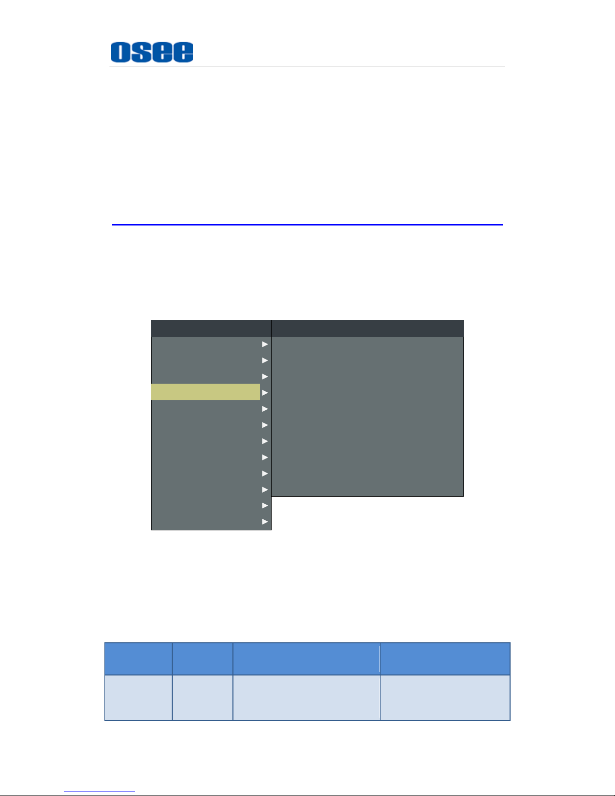
MARKER MAT
The marker mat marks the outside area of the marker display with the
appointed transparency.
For example, set ASPECT as 16:9, AREA MARKER as 4:3, and SAFETY
AREA as 95%, then, the comparison of the three MARKER MATs are as
shown in Figure 5.1-11:
MARKER MAT=OFF MARKER MAT=HALF MARKER MAT=BLACK
Figure 5.1-11 MARKER MAT
All markers will be hidden in the following modes though the corresponding
marker is enabled (the value is not OFF): NATIVE, H/V DELAY, PBP, WIPE
Page 45
Functionality of the Main Menu
39
or BLENDING).
The AREA MARKER, CENTER MARKER and SAFETY MARKER feature
are available only when the MARKER item is set to ON.
The safety marker area will change with the area marker.
The cross hatch lines will display only in the single image or in PIP mode
when
CROSS HATCH
is ON.
5.1.4 AUDIO Menu
The AUDIO menu items are used to adjust the audio parameters, the
menu items are as shown in Figure 5.1-12:
CLOSED CAPTION
DISPALY
CONFIG
COLOR TEMP
FUNCTION KEY
GPI
MAIN
AUDIO
MARKER
INPUT SELECT
STATUS
IMD
KEY INHIBIT
METER DIRECTION
AUDIO SOURCE
SPEAK OUT L
SPEAK OUT R
AUDIO METER
METER SELECT
METER POSITION
METER DIS MODE
REF LEVEL
AUDIO
HORIZONTAL
AUDIO1
EBD CH1
EBD CH1
OFF
CH1-2
TOP
MODE1
-20dB
OVER LEVEL -10dB
Figure 5.1-12 AUDIO Menu
The relationship of Items, Default Value, Domain Range and Description
of the sub-item is shown in Table 5.1-4:
Table 5.1-4 The Description of AUDIO Menu Items
Items
Default
Value
Domain Range
Description
AUDIO
SOURCE
EDB
EDB: embedded signal
AUDIO1: external
signal1
Select the audio source.
When there is no sync in
and the input signal is
Page 46
Functionality of the Main Menu
40
Items
Default
Value
Domain Range
Description
AUDIO2: external
signal2
UNDEF: no signal
not HDMI/SDI1/SDI2,
you can select only
UNDEF, AUDIO1 or
AUDIO2.
SPEAK
OUT L
EBD CH1
When the audio source is
EBD, the range of this item
is EDB CH1~ EDB CH16.
Left speaker, select a
channel according to the
type of audio source.
SPEAK
OUT R
EDB CH2
When the audio source is
EBD, the range of this item
is EDB CH1~ EDB CH16.
Right speaker, select a
channel according to the
type of audio source.
AUDIO
METER
OFF
OFF/ON
Set whether to display
the audio meter.
METER
SELECT
CH1-2
CH1-2
G1
G2
G3
G4
G1+G2
G1+G3
G1+G4
G2+G3
G2+G4
G3+G4
G1-G4
Select a meter display
mode. Each G* contains
four channels, and each
CH* means a channel
with number.
METER
DIRECTION
VERTICAL
VERTICAL
HORIZONTAL
Select the displayed
direction of audio meter.
METER
POSITION
BOT
LEFT/
BOTTOM
When the value of METER
DIRECTION is VERTICAL
, you can choose the
followings for Meter
Position:
BOT LEFT: bottom left
BOT RIGHT: bottom
right
TOP RIGHT: top right
TOP LEFT: top left
When the value of METER
DIRECTION is
HORIZONTAL, you can
choose the followings for
Meter Position:
BOTTOM
TOP
Select the displayed
position of audio meter.
Page 47
Functionality of the Main Menu
41
Items
Default
Value
Domain Range
Description
METER DIS
MODE
MODE1
MODE1: simple audio
meter
MODE2: audio meter
with channel number
MODE3: audio meter
with channel number
and dB value
Select the displayed
mode for audio meter.
REF LEVEL
-20dB
-20dB/-18dB
Select the reference
level.
OVER
LEVEL
-10dB
-10dB
-8dB
-6dB
-4dB
-2dB
Select the overload
level.
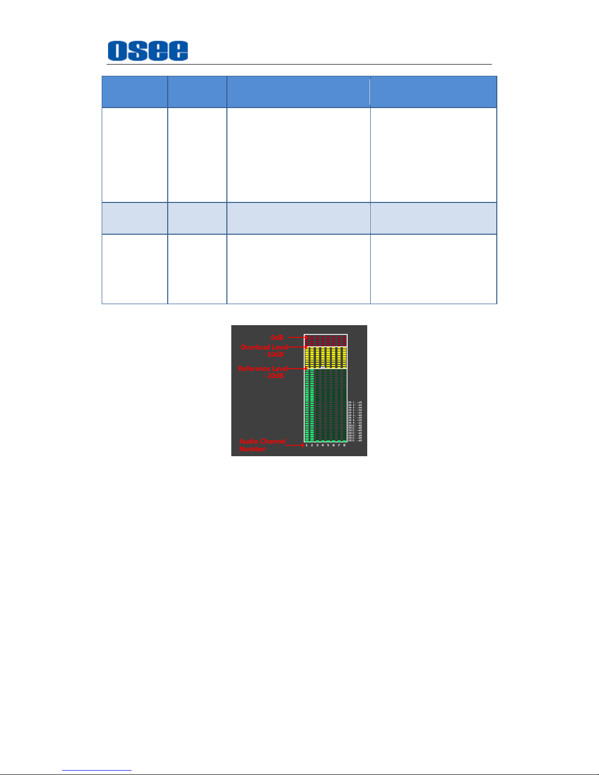
The appearance of Meter is as shown in Figure 5.1-13:
Figure 5.1-13 Audio Meter
METER SELECT
and
METER DIS MODE
control the operational
characteristics of Audio Metering, the former controls the amount of
channels displayed in a meter.
As shown in Figure 5.1-14, the meter displays at the left of the screen
vertically, the METER SELECT is G1+G2, and the METER DIS MODE
is MODE3, you can see the meter displays audio channel numbers and
audio values beside the meter. There is a white rectangle frame with two
white level lines in the meter, the upper is the over level line, and the
lower is the reference level line. If the audio value is higher than the
reference level, the audio bar over the reference level line will display
yellow, and if the audio value is higher than the over level, the audio bar
over the over level line will display red.
Page 48
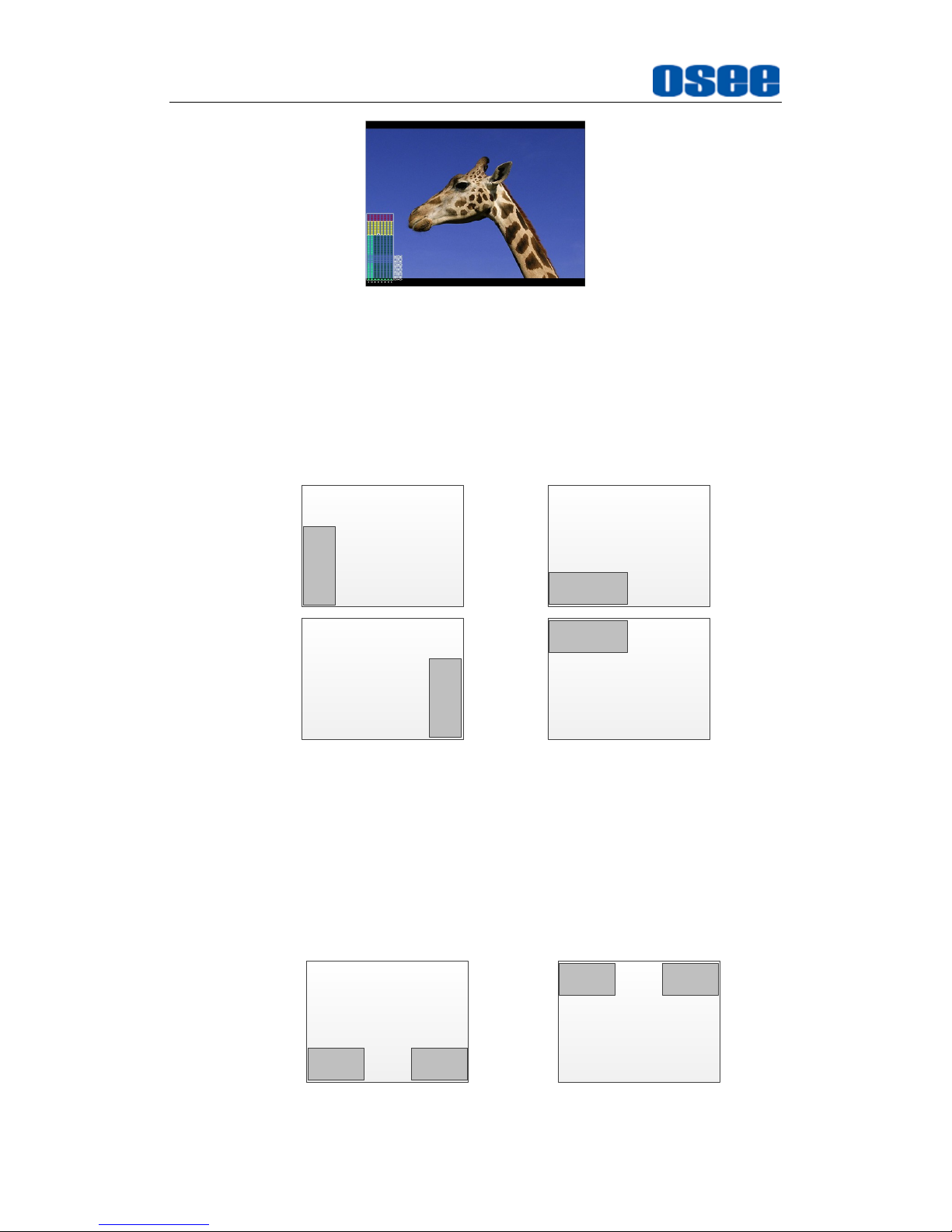
Functionality of the Main Menu
42
Figure 5.1-14 The Position of the Audio Meter On Screen
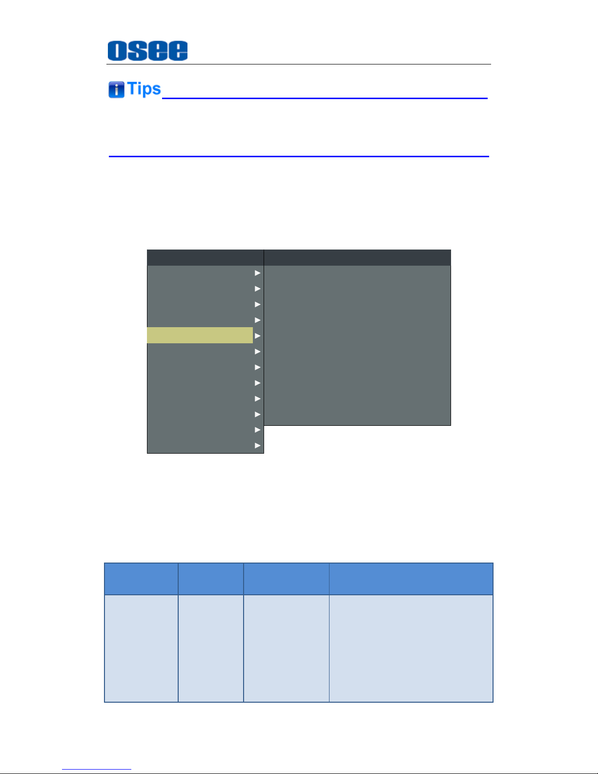
The position of Meter is controlled by
METER DIRECTION
and
METER POSITION
, the position of the meter on the screen is as
follows: BOT LEFT VERTICAL, BOT RIGHT VERTICAL, TOP LEFT
VERTICAL, TOP RIGHT VERTICAL, BOTTOM HORIZONTAL and
TOP HORIZONTAL. For example, the illustrations of some of the
positions are as shown in Figure 5.1-15:
Vertical
Left
WFM
Vertical
Right
WFM
Horizontal
Bottom
WFM
Horizontal
Top
WFM
Figure 5.1-15 the Positions of Meter
Particularly, if the
METER SELECT
is
G1-4
, there will be 16 channels
displayed in audio meter, and if the
METER DIRECTION
is
Horizontal
,
the audio meter will display two meters separately on both sides of the
screen. One displays 8 channels(1~8) on the bottom or top left of the
screen, and the other displays 8 channels(9~10) on the bottom or top
right of the screen, the bottom or top is decided by
METER POSITION
,
as shown in Figure 5.1-16:
Horizontal
Bottom
WFM
1~8
Horizontal
Top
WFM
9~16
WFM
1~8
WFM
9~16
Figure 5.1-16 the Positions of the 16-channels Meter
Page 49
Functionality of the Main Menu
43
The prerequisite for the available settings of the display mode and the
position of audio meter is that the
AUDIO METER
is ON.
5.1.5 DISPLAY Menu
The DISPLAY menu items are used to adjust the parameters displayed on
the screen, the menu items are as shown in Figure 5.1-17:
CLOSED CAPTION
AUDIO
CONFIG
COLOR TEMP
FUNCTION KEY
GPI
MAIN
DISPALY
MARKER
INPUT SELECT
STATUS
IMD
KEY INHIBIT
LINE WAVE NUMBER
STATUS DISPLAY
AFD DISPLAY
WFM POSITION
WAVE FORM TYPE
LINE WAVE
WAVE OVER LIMIT
WAVE UNDER LIMIT
WFM TRANS
DISPLAY
---
AUTO
OFF
LEFT
WAVE FORM
OFF
50
0
OPAQUE
TIME CODE OFF
Figure 5.1-17 DISPLAY SETUP Menu
The relationship of Items, Default Value, Domain Range and Description
of the sub-item is shown in Table 5.1-5:
Table 5.1-5 The Description of DISPLAY SETUP Menu Items
Items
Default
Value
Domain Range
Description
STATUS
DISPLAY
AUTO
OFF/AUTO
Set whether to display STD
information.
If the signal input is not equal to
"No signal" and this item is auto,
the status information will show
15 seconds when the status
changed, and then closed
automatically.
Page 50
Functionality of the Main Menu
44
Items
Default
Value
Domain Range
Description
AFD
DISPLAY
OFF
OFF/ON
Set whether to display AFD
information.
ON is an effective value to AFD
DISPLAY item only if the value
of STATUS DISPLAY is AUTO or
ON.
WFM FORM
TYPE
NORMAL
MODE1
MODE2
VECT100
VECT75
WAVE
FORM
OFF
Switch the display mode among
mode1, mode2, vector100,
vector75 and wave form.
LINE WAVE
OFF
OFF/ON
Set whether to show line wave,
as shown in Figure 5.1-18.
LINE WAVE
NUMBER
260
As shown in
Table 5.1-6.
Set the position of line WFM.
WFM OVER
LIMIT
50
50~100
Set the over limit of WFM.
WFM UNDER
LIMIT
0
0~50
Set the under limit of WFM.
WFM TRANS
OPAQUE
OPAQUE
TRANS1
TRANS2
TRANS3
Set the transparency of the
WFM.
WFM
POSITION
LEFT
LEFT: LEFT
BOT
RIGHT: BOT
RIGHT
Select the displayed position for
WFM.
TIME CODE
OFF
OFF
D-VITC
LTC
VITC
Set whether to display TC, and
select a mode for TC display.
Thereinto, the value of LINE WFM is different according to the type of
input signal, as shown in Table 5.1-6.
Table 5.1-6 The Description for LINE WFM Item
Input Signal
Default
Domain Range
576i50
310
23~623
480i60
261
22~524
Page 51
Functionality of the Main Menu
45
Input Signal
Default
Domain Range
720p
386
26~745
1080i50
560
21~1123
1080i60/59.94
1080sf23/23.97
1035i60
557
41~1120
1080p
561
42~1121
The comparison of a normal WFM/Vector and a Line WFM is as shown
in Figure 5.1-18:
LINE WFM
WFM
Figure 5.1-18 The LINE WFM and the WFM
You can call out the vectorscope or wave form and configure its display
mode through
DISPLAYWAVE FORM TYPE
, and configure its display
position through
DISPLAY WFM POSITION
.
Please refer to the international standard SMPTE2016-1-2007 for the
details about AFD display.
5.1.6 CLOSED CAPTION Menu
The CLOSED CAPTION menu items are used to set whether to display
caption on screen and set the display mode, the menu items are as shown
in Figure 5.1-19:
Page 52
Functionality of the Main Menu
46
AUDIO
CONFIG
COLOR TEMP
FUNCTION KEY
GPI
MAIN
CLOSED CAPTION
DISPALY
MARKER
INPUT SELECT
STATUS
IMD
KEY INHIBIT
SDI CC LOG
CLOSED CAPTION
CLOSED CAPTION
OFF
OFF
SDI CC TYPE
608 CHANNEL SEL
AUTO1
CC1
Figure 5.1-19 CLOSED CAPTION Menu
The relationship of Items, Default Value, Domain Range and Description
of the sub-item is shown in Table 5.1-7:
Table 5.1-7 The Description of CLOSED CAPTION Menu Items
Items
Default
Value
Domain Range
Description
SDI CC LOG
OFF
OFF/ON
Set whether to
display CC
information.
CLOSED
CAPTION
OFF
OFF/ON
Set whether to
display caption
information.
SDI CC TYPE
AUTO1
AUTO1: Select to set to
608(VBI) when the SD-SDI
signal is input or 608(708) when
the HD-SDI signal is input.
AUTO2: Select to set to
608(ANC) when the SD-SDI
signal is input or 608(708) when
the HD-SDI signal is input.
608(708): Select to display the
closed caption signal transmitted
by EIA/CEA-708 standards.
608(ANC): Select to display the
closed caption signal transmitted
by EIA/CEA-608 or
EIA/CEA-708standards.
Set the closed
caption type.
Page 53
Functionality of the Main Menu
47
Items
Default
Value
Domain Range
Description
608(VBI): Select to display the
closed caption signal of the
EIA/CEA-608 standards
transmitted by using the line 21.
608
CHANNEL
SEL
CC1
CC1
CC2
CC3
CC4
TEXT1
TEXT2
TEXT3
TEXT4
Set the display
mode for closed
caption for
608(708),
608(ANC) and
608(VBI).
5.1.7 CONFIG Menu
The CONFIG menu items are used to adjust the parameters defined by
customers, the menu items are as shown in Figure 5.1-20:
AUDIO
FUNCTION KEY
GPI
MAIN
CONFIG
COLOR TEMP
CLOSED CAPTION
DISPALY
MARKER
INPUT SELECT
STATUS
IMD
KEY INHIBIT
PIP POSITION
FAST MODE
FILM MODE DETECT
SUB IN TYPE
SUB IN SELECT
PIP SIZE
AUTO STANDBY
APPEATURE
CONFIG
HORIZONTAL
OFF
OFF
PBP
SDI1
LARGE
OFF
0
LOCK NUMBER 0
LANGUAGE ENGLISH
FLASH NUM
SDI ASSIST MODE
ONCE
OFF
SCREEN SAVER OFF
WIPE LINE DISPLAY WHITE
Figure 5.1-20 CONFIG Menu
The relationship of Items, Default Value, Domain Range and Description
of the sub-item is shown in Table 5.1-8:
Table 5.1-8 The Description of CONFIG Menu Items
Page 54
Functionality of the Main Menu
48
Items
Default
Value
Domain Range
Description
FAST MODE
OFF
OFF/ON
Set whether to display
in fast mode.
FILM MODE
DETECT
OFF
OFF/ON
Set whether to detect
film mode.
SUB IN
TYPE
PBP
OFF/PBP/PIP
/WIPE/BLENDING
Set the display mode
of the multiple images
on screen.
SUB IN
SELECT
SDI1
SDI1
SDI2
LINE1(CVBS)
LINE2(CVBS)
LINE2(Y/C)
LINE2(YPBPR)
HDMI
Set the source of slave
picture, refer to Table
5.1-10 for the details.
PIP SIZE
LARGE
SMALL/LARGE
Set the size of PIP.
PIP
POSITION
BOT LEFT
BOT LEFT: bottom left
BOT RIGHT: bottom
right
TOP RIGHT
TOP LEFT
Set the position of PIP.
BACK LIGHT
15
0~30
Adjust the back light.
AUTO
STANDBY
OFF
OFF/ON
Set whether to enable
the auto standby
mode.
APPERTURE
0
0~24
Set the picture
sharpness.
LOCK
NUMBER
XXXXXXXX
--
Set the lock number.
LANGUAGE
ENGLISH
ENGLISH/CHINESE/
DEUTSCH
Select a language
mode.
FLASH
NUMBER
ONCE
ONCE/TWICE
Set the flash times for
the screen.
SDI ASSIST
MODE
OFF
OFF: to display
normally.
INTERLACE MODE:
to insert the black line
within the interlace
signal.
H FLIP: to reverse the
picture horizontally.
Enable/disable to
display in the interlace
mode or the flip mode.
Page 55
Functionality of the Main Menu
49
Items
Default
Value
Domain Range
Description
SCREEN
SAVER
OFF
OFF/ON
Enable/disable to
display in the screen
saver.
WIPE LINE
DISPLAY
OFF
OFF/WHITE/RED/GREEN
/BLUE/YELLOW/CYAN
/MEGENTA/BLACK/
Set whether to display
the wipe line, and
select a color for it.
1. Display Multiple Images
This monitor allows simultaneous display of two input signals on the
monitor’s screen. This function is convenient for making instant
adjustments between two input signals in just one monitor, and it helps
with color adjustment, setting of camera frames, special effects creation
and computer graphics (CG) work etc.
It will introduce the display mode, settings and signal source selection for
the multiple images on screen as follows.
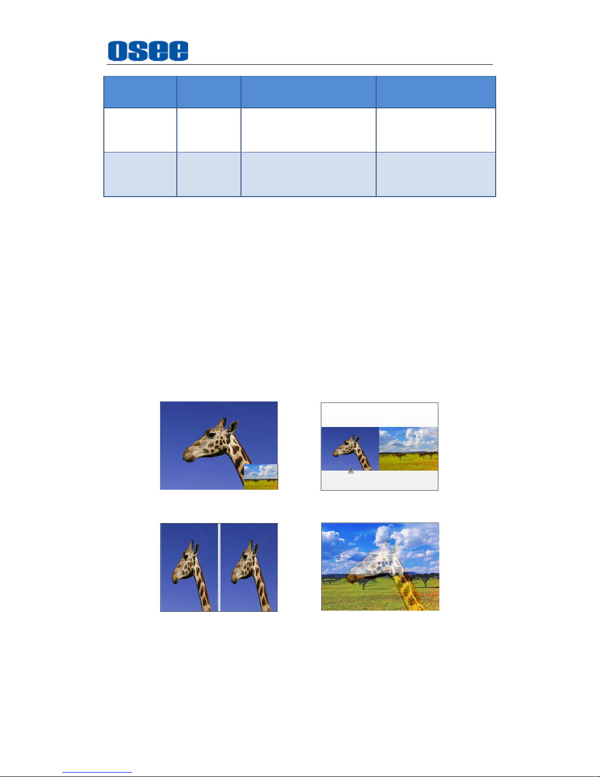
(1) Display Mode
This device provides four modes for picture & picture display: PIP, PBP,
WIPE, BLENDING, and the relevant relationship of the two pictures are
as shown in Figure 5.1-21:
INPUT1 INPUT2
INPUT1
INPUT2
PIP PBP
INPUT1
WIPE
INPUT1 INPUT2
BLENDING
INPUT2
Figure 5.1-21 Multiple Inputs
PIP
(Picture in Picture)
Page 56
Functionality of the Main Menu
50
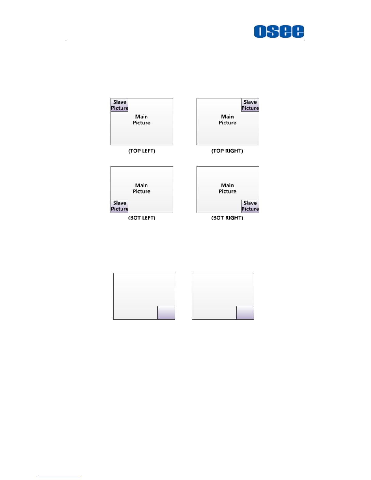
The two pictures generated by two input signals separately are
displayed one in another. One is displayed on full screen, called as the
main picture, and the other is displayed in an inset window, called as the
slave picture. In PIP mode, the relevant position relationship of the main
picture and the slave picture is as shown in Figure 5.1-22 :
Figure 5.1-22 The Position Relationship in PIP Mode
And you can adjust the display size by the PIP SIZE item, and there are
two kinds of outlines for the slave picture, as shown in Figure 5.1-23:
PIP SIZE=SMALL
PIP SIZE=LARGE
Main
Picture
Slave
Picture
Main
Picture
Slave
Picture
Figure 5.1-23 The Size for the Slave Picture
In PIP mode, it displays the WFM or Audio Meter only for the signal of
the main picture.
PBP
(Picture by Picture)
The two pictures generated by two input signals separately are
displayed side by side, and this function helps with white balance
adjustment, and determining shooting angles between two cameras etc.
In PBP mode, the size of the main picture is as large as the slave
picture’s, and the position relationship of the main picture and the slave
Page 57
Functionality of the Main Menu
51
picture is as shown Figure 5.1-24:
PBP
Main
Picture
Slave
Picture
Figure 5.1-24 PBP Mode
In PBP mode, it displays the WFM or Audio Meter only for the signal of
the current picture.
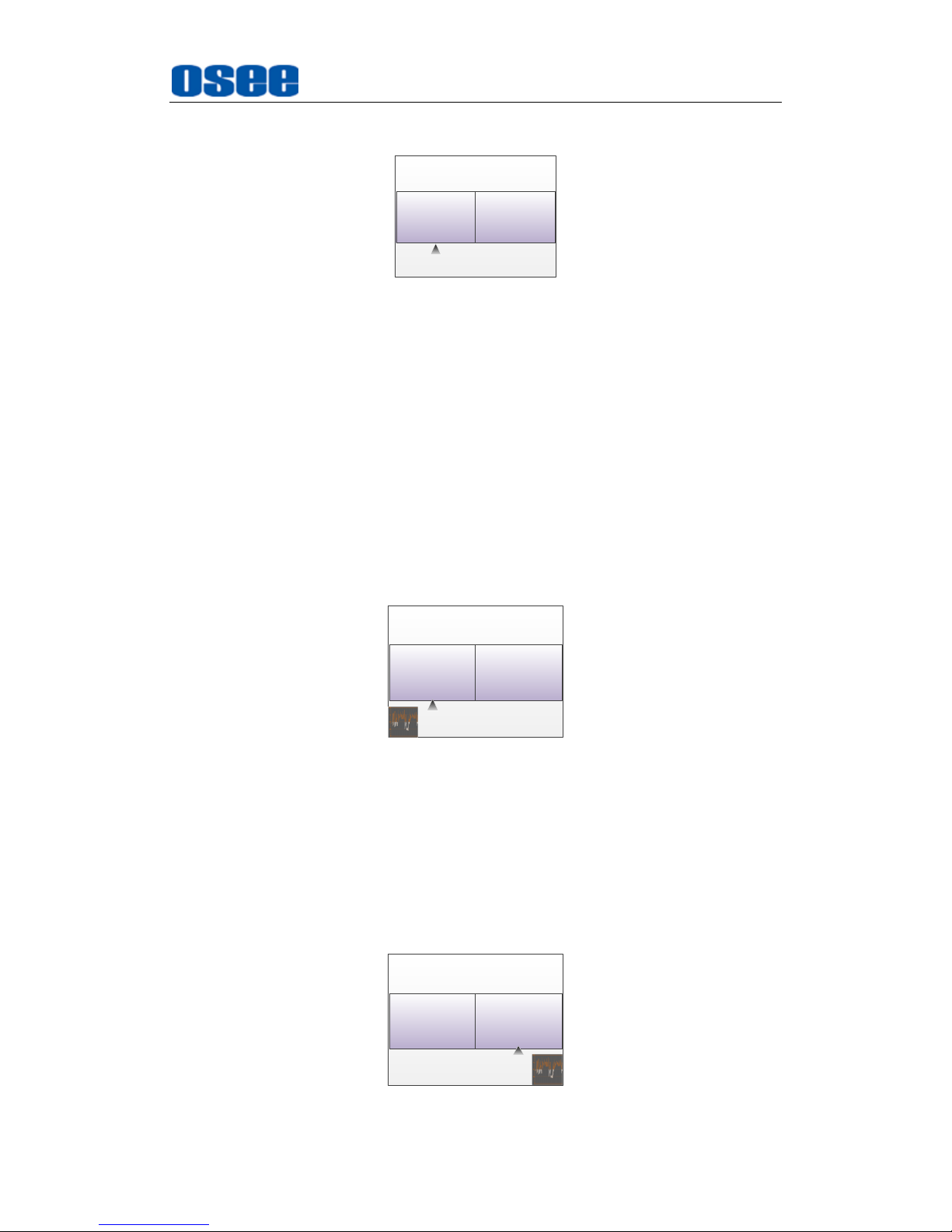
The current picture is labeled by a triangle, as shown in Figure 5.1-24,
at the bottom center of the picture. You can select the current picture by
the WIN SELECT command assigned to a function key.
When the main picture is set as the current picture, and the WFM is set
as displayed, the WFM could only be displayed at the left bottom of the
screen, as shown in Figure 5.1-25, and meantime, the Audio Meter will
be display only at the top position (Top left or Top right) at the screen in
case of collision.
PBP
Main
Picture
Slave
Picture
Figure 5.1-25 Position Relationship of WFM and the Current Picture
When the slave picture is set as the current picture, and the WFM is set
as displayed, the WFM could only be displayed at the right bottom of the
screen, as shown in Figure 5.1-26, and meantime, the Audio Meter will
be display only at the top position (Top left or Top right) at the screen in
case of collision.
PBP
Main
Picture
Slave
Picture
Page 58
Functionality of the Main Menu
52
Figure 5.1-26 Position Relationship of WFM and the Current Picture
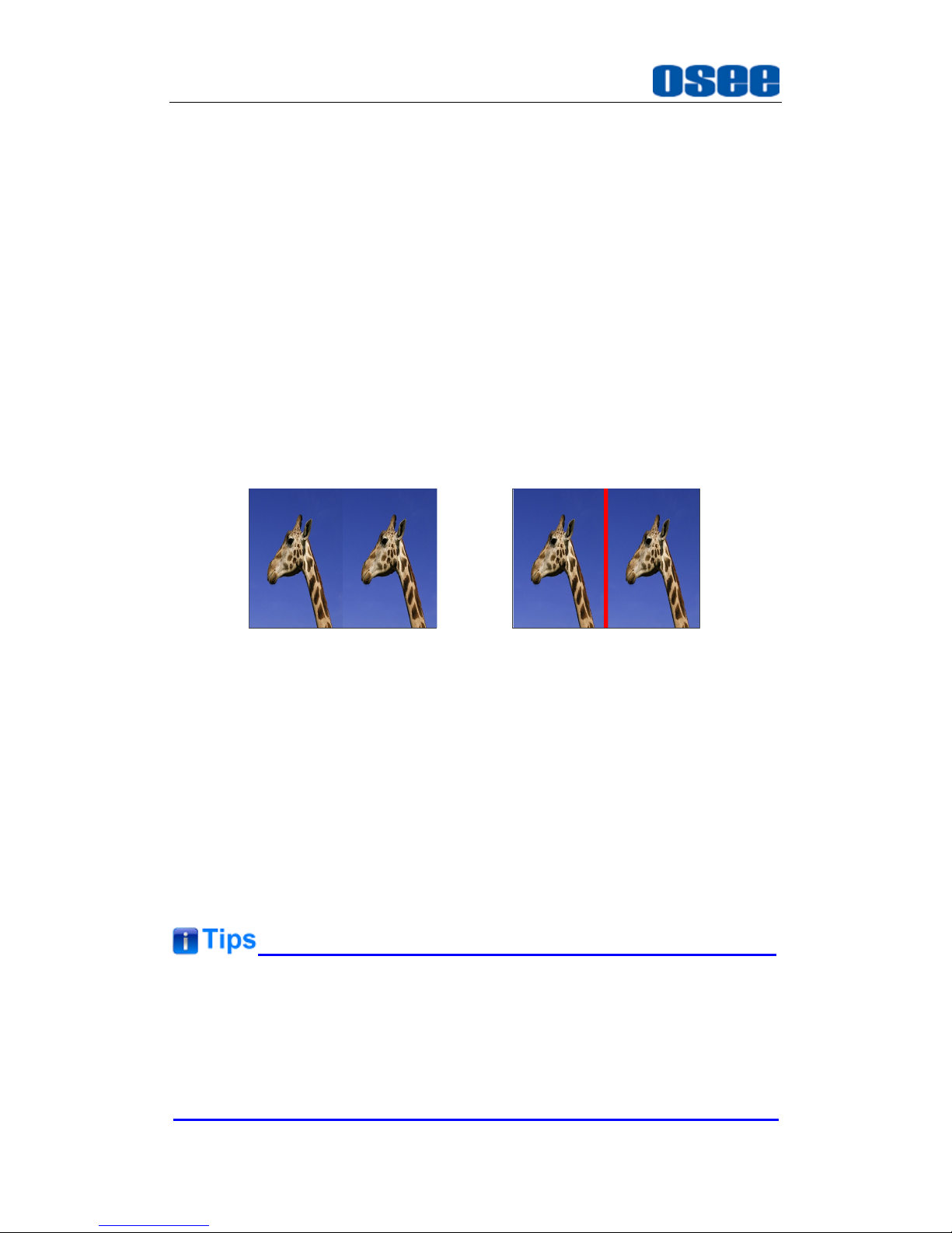
WIPE
The area of the two pictures to be displayed is selected using a vertical
WIPE pattern. This function is convenient when picture detail of the two
images must be examined on a pixel basis, and it is normally used to
review still images.
Set the ratio of the two pictures: In WIPE mode, use UP or
DOWN
key to adjust the compared ratio of the two pictures on screen. The
range is from -64 to 64.
Set the color of wipe line: In WIPE mode, select the menu item
Config WIPE LINE DISPLAY
for the color and the appearance
of wipe line, as shown in Figure 5.1-27:
INPUT1
WIPE LINE DISPLAY=OFF
INPUT2 INPUT1 INPUT2
WIPE LINE DISPLAY=RED
Figure 5.1-27 Wipe Line Display Mode
BLENDING
The two pictures are overlapped for display in blending mode, and the
mix ratio is adjustable. This function is useful to verify whether a
foreground signal is accurately keyed into the background signal, or
when combining shoots with live action and computer-generated
effects.
In BLENDING mode, use UP or DOWN key to adjust the mix ratio of the
two pictures on screen.
Make sure the two input signals compared in WIPE mode or BLENDING
mode must be full synchronization.
Set a mode for picture & picture display in the menu item
CONFIG SUB
IN TYPE DISPLAY
.
Page 59
Functionality of the Main Menu
53
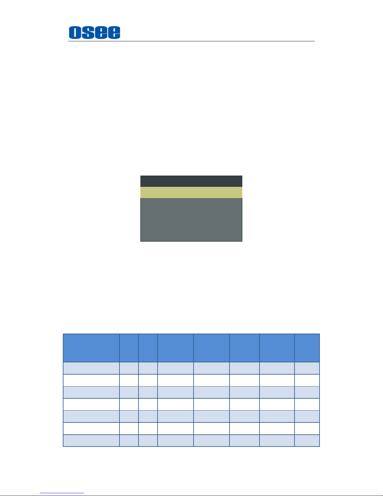
(2) Set Display Mode
The selection for picture & picture display mode contains the following
items: OFF, PBP, PIP, WIPE and BLENDING, you can switch the
selection as instructed below:
Method 1: By menu item.
Select the menu item Config SUB IN TYPE, use ENTER, UP or
DOWN key to select a display mode.
Method 2: By function key.
Set PBP function to one function key (F1~F5). Select the menu item
FUNCTION KEY F1 for example, and assign its sub-item value as
PBP, as shown in Figure 5.1-28:
F1 WIPEPBP
F2 OFFNATIVE
FUNCTION
F3 4:3ASPECT
F4 MAINWIN SELECT
F5 NORMALSCAN
Figure 5.1-28 Set the Function Key as PBP
(3) Scope for the signal source of the slave picture
The selection scope of the signal source for the slave picture will be
changing with the main picture's source, as shown in Table 5.1-10:
Table 5.1-9 The Relationship of the Signal Source for Slave Picture and
Main Picture
Signal Source for
Main Picture
\ Signal Source for
Slave Picture
SDI1
SDI2
LINE1
(CVBS)
LINE2
(CVBS)
LINE2
(Y/C)
LINE2
(YPSPR)
HDMI
SDI1
SDI2
LINE1(CVBS)
LINE2(CVBS)
LINE2(Y/C)
LINE2(YPBPR)
HDMI
Page 60
Functionality of the Main Menu
54
The input signal information of the main picture displays at the top left
corner of the screen, and the one of the slave picture displays at the top
right corner of the screen.
Set the signal source for the main picture: press
INPUT
key on the
front panel to display the SOURCE list, select an input signal source as
the main source.
Set the signal source for the slave picture: press
MENU
key on the
front panel to display the OSD menu list, and select the menu item
CONFIG SUB IN SELECT
to set an input signal source as the slave
source.
Select input source format for LINE2: For the LINE2(CVBS) interface, the
LINE2(Y/C) interface and the LINE2(YPSPR) interface share the same
group of physical interfaces, select the signal source format for LINE2
according to the line connection mode. When select a signal source format
for LINE2, you can set the menu item
INPUT SELECTLINE2
as CVBS,
LINE2(Y/C) or LINE2(YPBPR), in addition, press INPUT button to pop up
the source list for LINE2 selection.
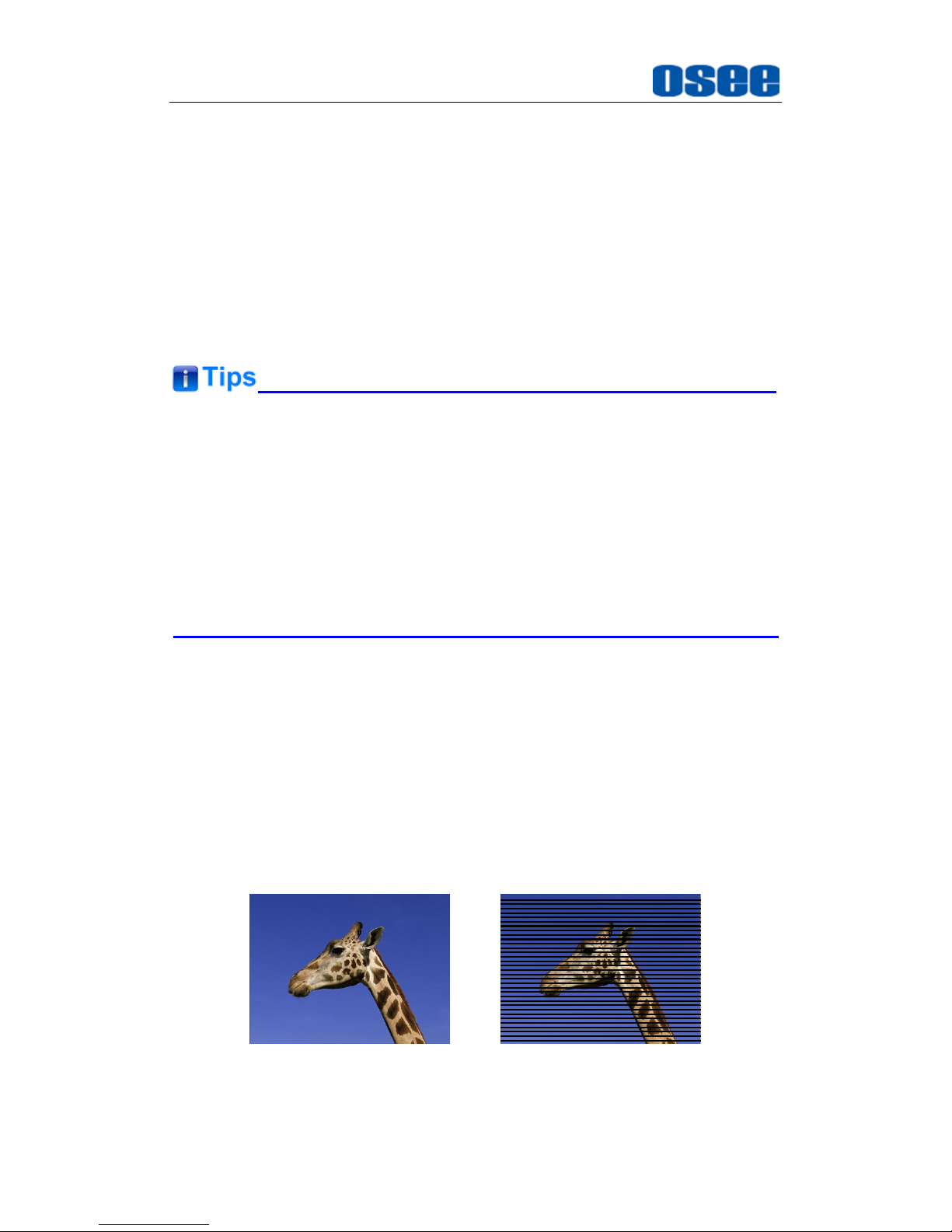
2. Set SDI ASSIST MODE
Interlace Mode
Interlace Display mode offers faithful reproduction of the input signal, the
picture is displayed in interlace mode by inserting the black line without I/P
conversion processing. The picture near the original quality of the input
signal is monitored.
Select the menu item
CONFIG SDI ASSIST MODEN
to be set to
ITERLACE MODE,
thus to display these inputs as a true interlace display.
The display result in the
INTERLACE MODE
is as shown in Figure 5.1-29:
INTERLACEOFF
Figure 5.1-29 Interlace Mode
Page 61
Functionality of the Main Menu
55
The
INTERLACE MODE
function is not available in PIP, PBP, WIPE, FLIP,
or BLENDING mode.
The
INTERLACE MODE
function is available for SDI inputs.
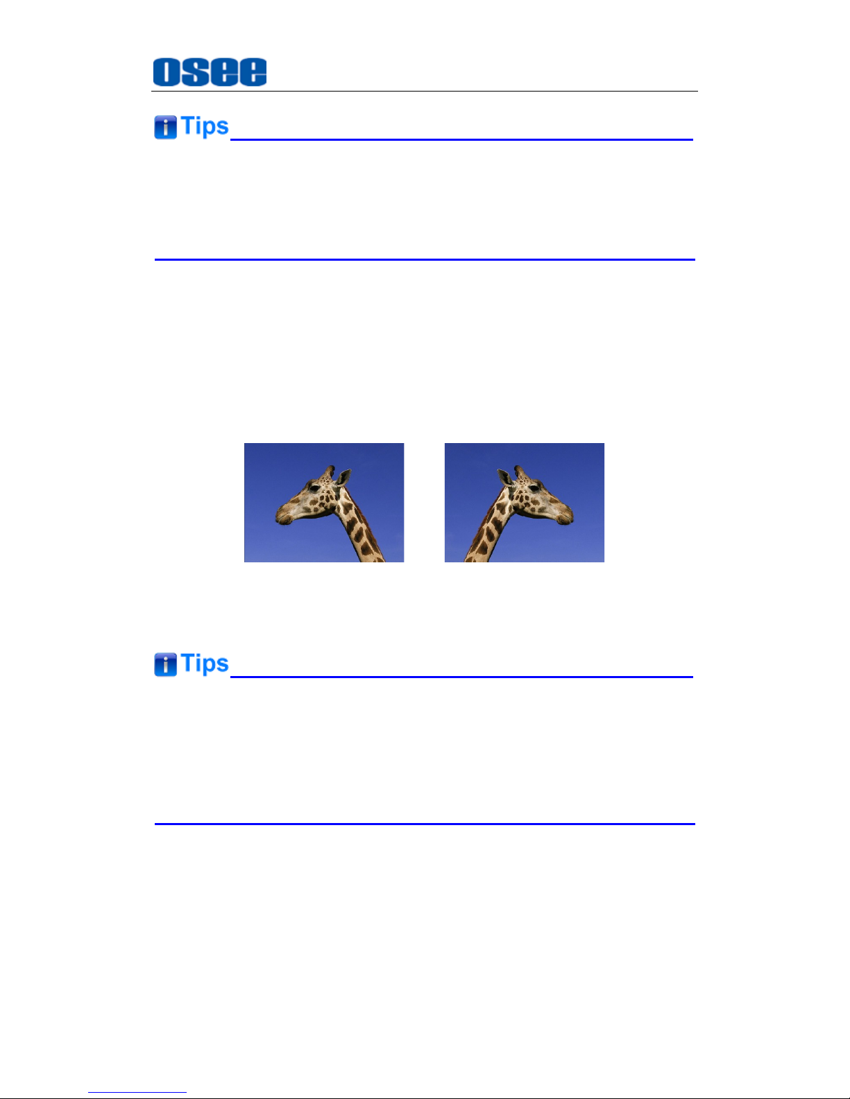
FLIP Mode
The input signal has been inverted horizontally by a mirror type in FLIP
Display mode.
Select the menu item
CONFIG SDI ASSIST MODEN
to be set to
H FLIP,
thus to inverse these inputs horizontally.
The display result in the
Horizontal FLIP MODE
is as shown in Figure
5.1-30:
OFF FLIP HORIZONTALLY
Figure 5.1-30 Horizontal Flip Mode
The
H FLIP MODE
function is not available in WIPE, INTERLACE, or
BLENDING mode.
The Wave Form of the input signal in
H FLIP
mode will not be inversed
horizontally.
3. Screen Saver
The Screen Saver function is used to detect a still image on the screen, in
order to protect the screen of the monitor
ON: When a still image is displayed on the screen for 10 minutes or
more, the brightness of the screen is automatically reduced to its
lowest to prevent burn-in of the screen(Contrast=0). The brightness
returns to normal if you input a moving image or operate any key on
Page 62
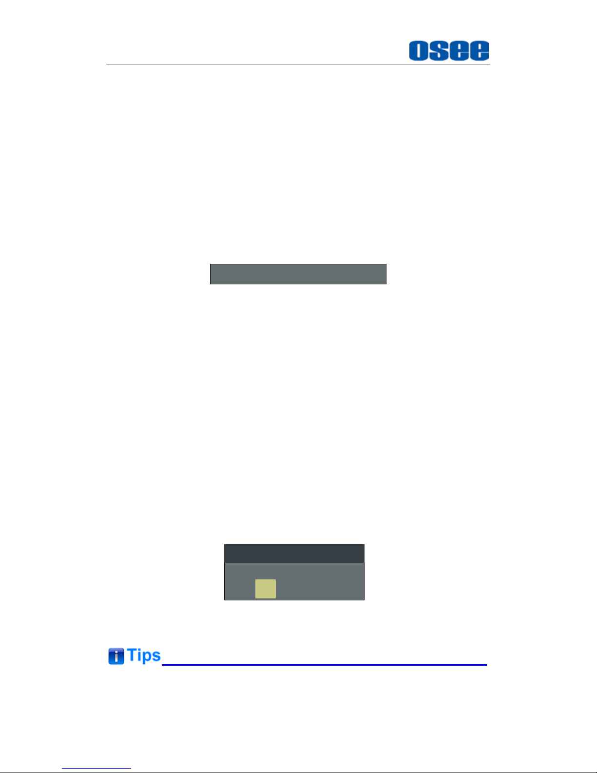
Functionality of the Main Menu
56
the front panel, meanwhile, the
POWER
indicator starts flashing
rapidly for one minute (it flashes in turn with red, green, yellow, white
color) before the screen saver is activated. After that, the flashing goes
slowly in red when the screen saver is activated.
OFF
: Disables the screen saver function.
4. Auto Standby
The Auto Standby function is used to set the status of the monitor when
the Power button is turned on or off.
ON: AUTO STANDBY
is set to ON to enable the auto standby mode.
Thus, the auto standby will be activated when detecting no signal input
or signal disappeared for 10 seconds or more, and there will be a
prompt during the process, as shown in Figure 5.1-31:
Going into Standby Mode
Figure 5.1-31 Entering the Auto Standby Mode
Press POWER button when the monitor is in operation mode, it will go
into auto standby mode, and the POWER indicator is lit in yellow. Then,
press POWER button again when the monitor is in auto standby mode,
it will start up and the POWER indicator is lit in green.
OFF: AUTO STANDBY
is set to
OFF
to disable the auto standby mode.
It will prompt a power off confirmation window when turn off the
monitor by press the
POWER
button.
Press POWER button when the monitor is in operation mode, it will
prompt a power off confirmation window, as shown in Figure 5.1-32,
press ∧(UP) or ∨(DOWN) button to select Yes or No.
Select Yes and press ENTER button to confirm, it will power off the
monitor, then the POWER indicator is lit in red, otherwise, Select No
and press ENTER button to confirm, it will cancel the power off
operation, and the POWER indicator is still lit in green.
Are you sure to power off?
No
Yes
POWER OFF CONFIRM
Figure 5.1-32 Prompt for Power Off
When the AUTO STANDBY is set to ON, the device will be standby when
Page 63
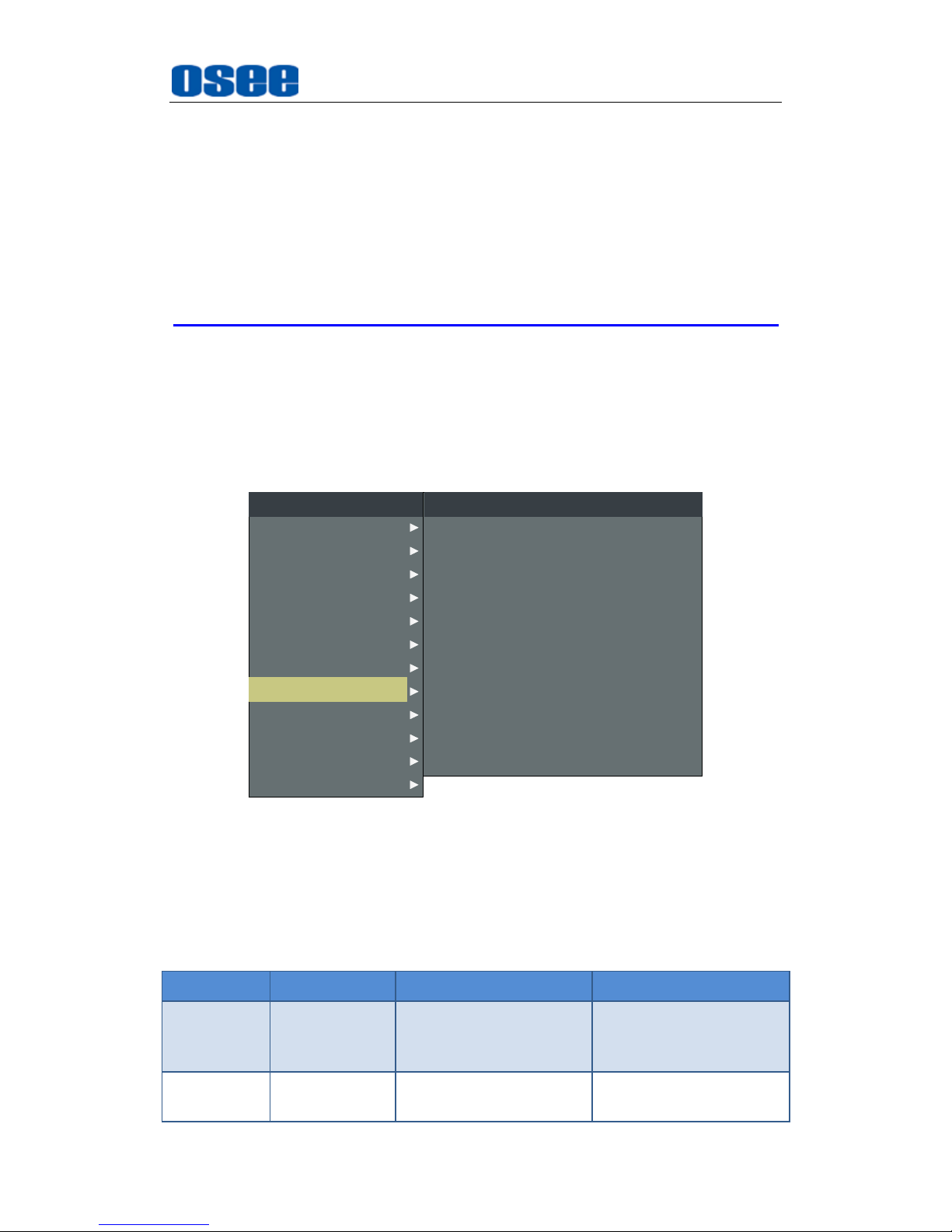
Functionality of the Main Menu
57
the signal is disappeared for 10s.
The length of LOCK NUMBER is up to 8 characters, you can use the
combination of these characters: number (0 to 9) and letter (A to Z). Press
ENTER
to edit the LOCK NUMBER, than use UP or
DOWN
to select
characters, than press
ENTER
to go to next character, press
MENU
to exit
editor.
5.1.8 COLOR TEMP Menu
The COLOR TEMP menu items are used to adjust GAMMA, the color
temperature parameters and the color balance, etc. The menu items are
as shown in Figure 5.1-33:
AUDIO
CONFIG
FUNCTION KEY
GPI
MAIN
COLOR TEMP
CLOSED CAPTION
DISPALY
MARKER
INPUT SELECT
STATUS
IMD
KEY INHIBIT
GREEN BIAS
COLOR TEMP
RED GAIN
GREEN GAIN
BLUE GAIN
RED BIAS
BLUE BIAS
0
D65
128
128
128
0
0
COLOR TEMP
COPY FROM
RESET
D65
COLOR SPACE AUTO
GAMMA 2.2
Figure 5.1-33 COLOR TEMP Menu
The relationship of Items, Default Value, Domain Range and Description
of the sub-item is shown in Table 5.1-10:
Table 5.1-10 The Description of COLOR TEMP Menu Items
Items
Default Value
Domain Range
Description
GAMMA
2.2
2.2
2.4
D-CINE
Set GAMMA.
COLOR
TEMP
D65
USER1:
Customized by user
Set color temperature
Page 64
Functionality of the Main Menu
58
Items
Default Value
Domain Range
Description
USER2:
Customized by user
D55: 5500K
D61: 6100K
D65: 6500K
D93: 9300K
D-CINE
RED GAIN
128
0~256
Adjust the Red Gain
GREEN
GAIN
128
0~256
Adjust the Green Gain
BLUE GAIN
128
0~256
Adjust the Blue Gain
RED BIAS
0
-127~127
Adjust the Red Offset
GREEN
BIAS
0
-127~127
Adjust the Green Offset
BLUE BIAS
0
-127~127
Adjust the Blue Offset
COPY
FROM
D65
D55: 5500K
D61: 6100K
D65: 6500K
D93: 9300K
Copy this parameter
value to USER
RESET
--
--
Reset the Gain and
Offset values to the
product originals
COLOR
SPACE
EBU
AUTO/EBU/SMPTE-C/
ITU-709/D-CINE/USER
Select the color matrix
Hereinto, the available range for various color space and color
temperature is different from the value of GAMMA, the details are as
shown in Table 5.1-11:
Table 5.1-11 The Relationship of COLOR TEMP and GAMMA and
COLOR SPACE
GAMMA
COLOR SPACE
COLOR TEMPERATURE
AUTO
EBU
SMPTE-C
ITU-709
D-CINE
USER
2.2
USER1/USER2/D55/D61/D65/D93
2.4
USER1/USER2/D55/D61/D65/D93
2.6(D-CINE)
USER1/USER2/D-CINE
Page 65
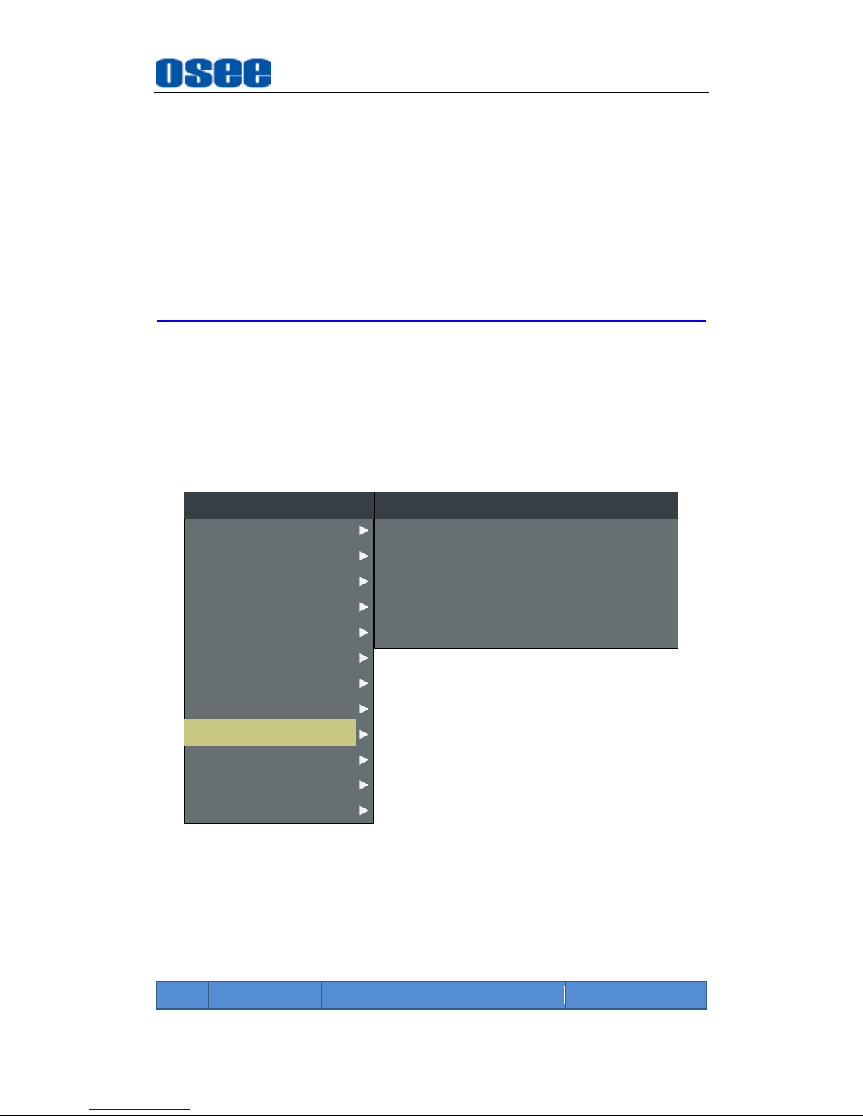
Functionality of the Main Menu
59
The items about RED/GREEN/BLUE GAIN and BIAS are available only in
USER1 and USER2 mode. If the COLOR TEMP is set to
USER1
or
USER2
with customized settings, you can select the menu item
COLOR TEMP
RESET
command to restore product originals for Gains and Offsets, and
press
ENTER
button to confirm the reset operation.
The default luminance is 48cd/m2 if GAMMA is set as D-CINE, and the
default luminance is 100cd/m2 if GAMMA is set as 2.2 or 2.4.
5.1.9 FUNCTION KEY Menu
The FUNCTION KEY menu items are used to assign function to the
function key (F1~F5) on the front panel, and adjust the value of the
function parameter. The menu items of FUNCTION KEY are as shown in
Figure 5.1-34:
AUDIO
GPI
MAIN
FUNCTION KEY
CONFIG
COLOR TEMP
CLOSED CAPTION
DISPALY
MARKER
INPUT SELECT
STATUS
IMD
KEY INHIBIT
F1
F2
FUNCTION KEY
SCAN
NATIVE
F3
F4
ASPECT
OFF
F5 OFF
Figure 5.1-34 FUNCTION KEY Menu
The relationship of Items, Default Value, Domain Range and Description
of the sub-item is shown in Table 5.1-12:
Table 5.1-12 The Description of FUNCTION KEY Menu Items
Items
Default Value
Domain Range
Description
Page 66
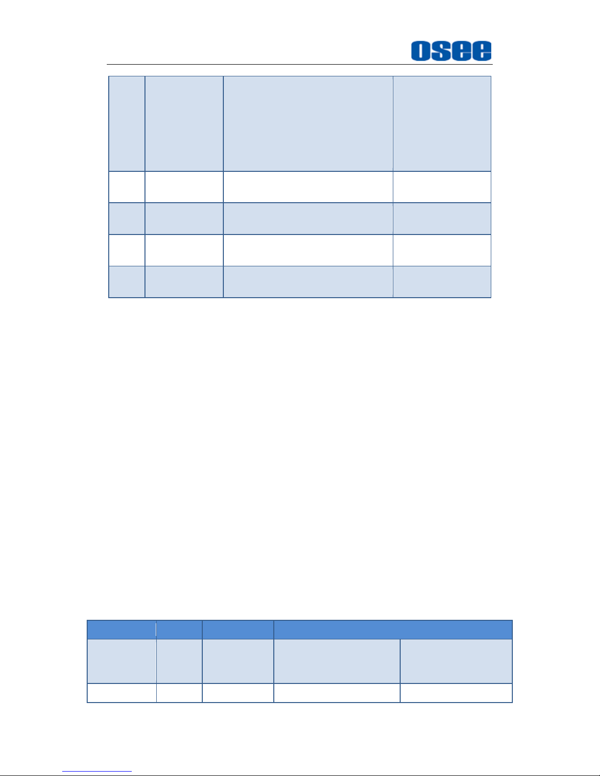
Functionality of the Main Menu
60
F1
SCAN
SCAN, NATIVE, ASPECT, BLUE
ONLY, MONO, MARKER, H/V
DELAY, AUDIO METER, FAST
MODE, TC, IMD, MUTE, PBP,
CC, FREEZE, WIN SELECT,
FOCUS ASSIST, LUMA ZOOM
CHECK, UNDEF
Set a function to
F1 button
F2
NATIVE
the same as F1
Set a function to
F2 button
F3
ASPECT
the same as F1
Set a function to
F3 button
F4
UNDEF
the same as F1
Set a function to
F4 button
F5
UNDEF
the same as F1
Set a function to
F5 button
1. SCAN
This product supports the following scan modes:
NORMAL OVER UNDER
Set the function button as [SCAN], press the button continuously to
activate various scan modes.
OVER: Zooms in/out of the image to 96% of its original size
without changing the aspect ratio.
NORMAL: Zooms in/out of the image without changing the aspect
ratio.
UNDER: Zooms in/out of the image without changing the aspect
ratio. Also, displays the data at the top of the horizontal blanking
block.
2. ASPECT
Set the aspect ratio of the screen, it is different from the formats of the
input signals, and the details are as shown in Table 5.1-13:
Table 5.1-13 The Relationship of Input Signal Formats and Its Aspects
Input Signal
Default
Value Range
Input Signal Formats
SD
4:3
4:3
16:9
PAL
NTSC
480I60/59.94
576I50
480P60/59.94
576P50
HD
16:9
16:9
720P24/23.97
1080I50
Page 67
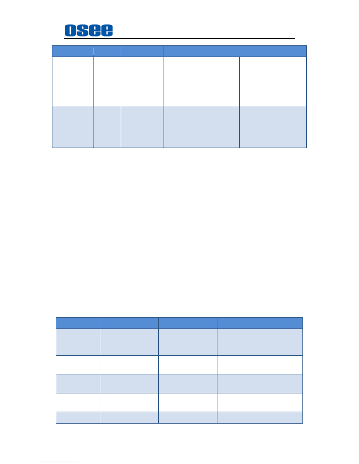
Functionality of the Main Menu
61
Input Signal
Default
Value Range
Input Signal Formats
2.39:1
720P25
720P30/29.97
720P50
720P60/59.94
1080SF24/23.97
1035I60/59.94
1080I60/59.94
1080P24/23.97
1080P25
1080P30/29.97
1080P50
1080P60/59.94
2K
1.896:1
1.896:1
2.39:1
2048X1080PSF24/23.97
2048X1080PSF25
2048X1080PSF30/29.97
2048X1080P24/23.97
2048X1080P25
2048X1080P30/29.97
2048X1080P48/47.94
2048X1080P50
2048X1080P60/59.94
3. FREEZE
Active this function to freeze the current frame displayed, press the
function button again to release the freeze and continue to display.
4. BLUE ONLY
It is to activate BLUE ONLY mode that will remove red and green from the
input signal and display the screen only under a blue signal.
5. MONO
It is to activate MONO mode that will display the screen in monochrome
presentation, inactivate this mode to display the screen in color mode.
6. Value for function keys
The indicator of the function key will light in white when press it down, and
it will light in green when the value of the function key is assigned as the
special value, the values of the function keys and their special values are
listed as shown in Table 5.1-14:
Table 5.1-14 The Value Range and the Special Value for FUNCTION
Keys
Value Items
Special Value
Value Range
Description
SCAN
OVER SCAN
UNDER SCAN
OVER SCAN
NORMAL
UNDER SCAN
Set the scan mode
NATIVE
ON
ON/OFF
Enable or disable the native
mode
ASPECT
As shown in Table
5.1-13
As shown in Table
5.1-13
Set the aspect ration
BLUE ONLY
ON
ON/OFF
Enable or disable the blue
only mode
MONO
ON
ON/OFF
Enable or disable the mono
Page 68
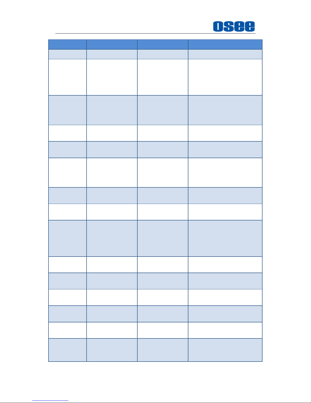
Functionality of the Main Menu
62
Value Items
Special Value
Value Range
Description
mode
MARKER
ON
ON/OFF
Enable or disable the
display of markers, the
function is as the same as
the setting of the menu item
“MARKER”” MARKER”
H/V DELAY
H DELAY
V DELAY
H/V DELAY
OFF
H DELAY
V DELAY
H/V DELAY
Enable or disable the
display of H/V DELAY, and
set its display mode
AUDIO
METER
ON
ON/OFF
Enable or disable the audio
meter
FAST MODE
ON
ON/OFF
Enable or disable the fast
mode
TC
VITC
LTC
D-VITC
OFF
VITC
LTC
D-VITC
Enable or disable the
display of TC, and set its
display mode
IMD
ON
ON/OFF
Enable or disable the
display of IMD
MUTE
ON
ON/OFF
Enable or disable the mute
function
PBP
PBP
PIP
WIPE
BLENDING
OFF
PBP
PIP
WIPE
BLENDING
Enable or disable the
display of multiple screens,
and set its display mode
CC
ON
ON/OFF
Enable or disable the close
caption function
FREEZE
ON
ON/OFF
Enable or disable the
screen freeze mode
WIN SELECT
SUB
MAIN/SUB
Set the current screen icon
in PBP mode
FOCUS
ASSIST
ON
ON/OFF
Enable or disable the focus
assist function
LUMA ZOOM
CHECK
ON
ON/OFF
Enable or disable the luma
zoom check function
SDI ASSIST
MODE
INTERLACE
MODE
H FLIP
OFF
INTERLACE
MODE
Enable/disable to display in
the interlace mode or the
flip mode.
Page 69
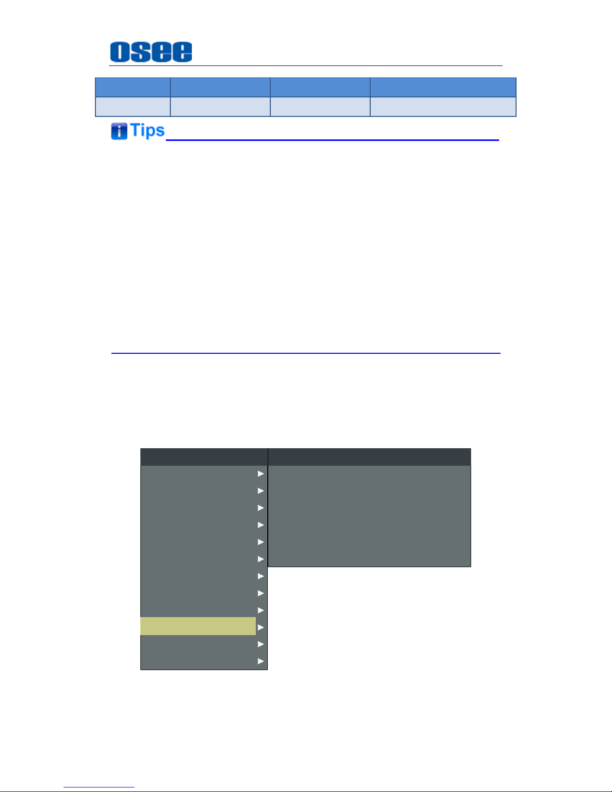
Functionality of the Main Menu
63
Value Items
Special Value
Value Range
Description
H FLIP
Press F1~F5 button to activate the assigned function and adjust the
parameter value.
The
SCAN
mode or the ASPECT mode is not selectable when Native mode
is set to ON.
Particularly, when the
PBP
function is assigned to a function key, press this
function key to select the display mode for picture & picture display, and if
the function value is
WIPE
or
BLENDING
, you can use ∧(
UP)
or
∨
(
DOWN)
key to assist in adjusting the compared ratio for WIPE or the mix
ratio for BLENDING.
5.1.10 GPI Menu
The GPI menu items are used to define functions to GPI1~GPI6, the
menu items are as shown in Figure 5.1-35:
AUDIO
MAIN
GPI
FUNCTION KEY
CONFIG
COLOR TEMP
CLOSED CAPTION
DISPALY
MARKER
INPUT SELECT
STATUS
IMD
KEY INHIBIT
GPI1
GPI2
GPI
TALLY GREEN
TALLY RED
GPI3
GPI4
NATIVE
BLUE ONLY
GPI5 MONO
GPI6 H/V DELAY
Figure 5.1-35 GPI Menu
Page 70
Functionality of the Main Menu
64
The relationship of Items, Default Value, Domain Range and Description
of the sub-item is shown in Table 5.1-15:
Table 5.1-15 The Description of GPI Menu Items
Items
Default Value
Domain Range
Description
GPI1
TALLY
GREEN
UNDEF, AREA MARKER,
CENTER MARKER, SAFETY
MARKER, ASPECT, NATIVE,
OVER SCAN, UNDER SCAN,
BLUE ONLY, MONO,
DELAY, V DELAY, H/V
DELAY, SDI1, SDI2, LINE1,
LINE2, HDMI, TALLY
GREEN, TALLY RED
Set a function to GPI1
GPI2
TALLY RED
the same as GPI1
Set a function to GPI2
GPI3
UNDEF
the same as GPI1
Set a function to GPI3
GPI4
UNDEF
the same as GPI1
Set a function to GPI4
GPI5
UNDEF
the same as GPI1
Set a function to GPI5
GPI6
UNDEF
the same as GPI1
Set a function to GPI6
Assign functions to GPI1~GPI6, some is level triggered, and some is edge
triggered, refer to Table 5.1-16 for the details.
GPI control: when it changes it would be as a control value of response
control. If the level does not change, but there are other control caused by
changes in the control value, perform this change. When boot, detect the
GPI input status after initialization. If a GPI value is low, the monitor will
control the corresponding operation. The TALLY is directly control by the
level.
Table 5.1-16 The Description for GPI Items and Their Trigger
Items
Function
Trigger
AREA MARKER
Enable/Disable the display of
area marker.
Low: Enabled; High: Disabled
CENTER
Enable/Disable the display of
Low: Enabled; High: Disabled
Page 71
Functionality of the Main Menu
65
Items
Function
Trigger
MARKER
center marker.
SAFETY
MARKER
Enable/Disable the display of
safety marker.
Low: Enabled; High: Disabled
ASPECT
Set the aspect ratio.
Low: 16:9; High: 4:3
MONO
Switch between the
monochrome and color.
Low: MONO; High: NORMAL
OVER SCAN
Switch scan mode between
over and normal.
Low: OVER; High: NORMAL
UNDER SCAN
Switch scan mode between
under and normal.
Low: UNDER; High: NORMAL
BLUE ONLY
Switch between blue only
and normal.
Low: BLUE ONLY; High:
NORMAL
NATIVE
Switch between native and
normal.
Low: NATIVE(In center); High:
NORMAL
H DELAY
Switch between H delay and
normal.
Low: H DELAY; High: NORMAL
V DELAY
Switch between V delay and
normal.
Low: V DELAY; High: NORMAL
H/V DELAY
Switch between H/V delay
and normal.
Low: H/V DELAY; High:
NORMAL
SDI1
Switch the input source to
SDI1.
Switch at the falling edge, when
switching to the other input, exit.
SDI2
Switch the input source to
SDI2.
Switch at the falling edge, when
switching to the other input, exit.
LINE1
Switch the input source to
LINE1.
Switch at the falling edge, when
switching to the other input, exit.
LINE2
Switch the input source to
LINE2.
Switch at the falling edge, when
switching to the other input, exit.
HDMI
Switch the input source to
HDMI.
Switch at the falling edge, when
switching to the other input, exit.
TALLY GREEN
Light the green tally.
Low: ON; High: OFF
TALLY RED
Light the red tally.
Low: ON; High: OFF
5.1.11 IMD Menu
The IMD menu items are used to adjust the parameters defined for IMD
display, the menu items are as shown in Figure 5.1-36:
Page 72
Functionality of the Main Menu
66
AUDIO
CONFIG
FUNCTION KEY
GPI
MAIN
COLOR TEMP
CLOSED CAPTION
DISPALY
MARKER
INPUT SELECT
STATUS
IMD
KEY INHIBIT
IMD NAME
IMD DISPLAY
IMD COLOR
IMD CHARACTER
IMD PROTOCOL
IMD ID
BAUD RATE
LED TALLY
OSD TALLY MODE
IMD
XXXXXXXXXXXXXXXX
ON
RED
XXXXXXXXXXXXXXXX
LOCAL
0
38400
OFF
RG
IMD TALLY MODE T1
TALLY SOURCE STANDARD
Figure 5.1-36 IMD Menu
The relationship of Items, Default Value, Domain Range and Description
of the sub-item is shown in Table 5.1-17:
Table 5.1-17 The Description of IMD Menu Items
Items
Default
Value
Domain Range
Description
IMD DISPLAY
ON
OFF/ON
Set whether to display
IMD CHARACTER on
screen.
IMD COLOR
RED
RED
GREEN
YELLOW
WHITE
Set the color for IMD
CHARACTER.
IMD
CHARACTER
XXXXXXXX
--
Set the IMD string
displayed on the screen.
After entering this item,
press Up or Down to
choose your character
for this IMD string.
IMD
PROTOCAL
LOCAL
LOCAL
TSL3.1
TSL4.0
TSL5.0
IMAGE VIDEO
NETWORK
Select an IMD protocol
Page 73
Functionality of the Main Menu
67
Items
Default
Value
Domain Range
Description
IMD ID
0
0~255
Set the ID number for
each monitor
IMD NAME
XXXXXXXX
Set an IMD name for
each screen.
BAUD RATE
38400
2400/4800/9600/19200
/38400/57600/115200
Select a baud rate for
communication.
LED TALLY
ON
OFF/ON
Set whether to switch on
tally light.
OSD TALLY
MODE
RG
RG: Red/Green
GR: Green only
RGY:
Red/Green/Yellow
OFF: No tally light
Select the OSD Tally
mode. Only the TALLY
SOURCE is STANDARD
or STANDARD + IV422,
the setting is available.
IMD TALLY
MODE
T1
T1/T2/T1T2/T2T1/T1-/
T2-/T1T2-/T2T1-
Select the IMD Tally
mode.
Use this setting when
using the Image Video
tally control, this setting
will determine the state
which is selected.
TALLY
SOURCE
STANDARD
STANDARD/IMAGE
VIDEO/TSL
Select the source for
LED tally source
1. OSD TALLY MODE
The OSD TALLY MODE is available, only when setting IMD
MenuTALLY SOURCE as Standard. Set GPI1 as TALLY GREEN and
GPI2 as TALLY RED in GPI menu, the status of OSD TALLY and LED
TALLY when the Tally connector gets the high/low level are listed as
shown in Table 5.1-18:
Table 5.1-18 The status of OSD TALLY and LED TALLY When Triggering
the Tally Pins
OSD
TALLY
MODE
Green
TALLY
Red
TALLY
Illustration
LED
TALLY
OFF
0/1
0/1
Page 74
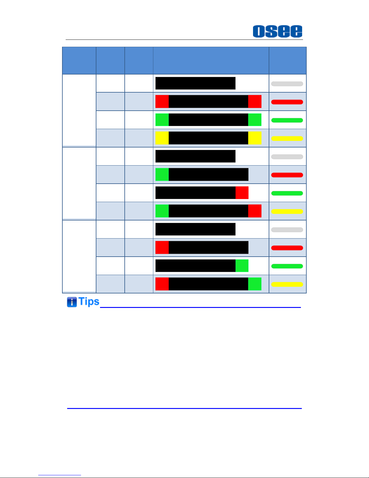
Functionality of the Main Menu
68
OSD
TALLY
MODE
Green
TALLY
Red
TALLY
Illustration
LED
TALLY
RGY
0
0
0
1
1
0
1
1
GR
0
0
0
1
1
0
1
1
RG
0
0
0
1
1
0
1
1
If IMD DISPLAY item is ON, the IMD CHARACTER in the black bar will
display on the center bottom of the screen.
The length of IMD NAME and IMD CHARACTER is up to 16 characters,
alphabets, numbers and special symbols are available. Press
ENTER
to
edit the IMD characters, than use
∧(Up)
and
∨(Down)
to select
characters, than press
ENTER
to go to next character, press
MENU
to exit
editor.
Page 75
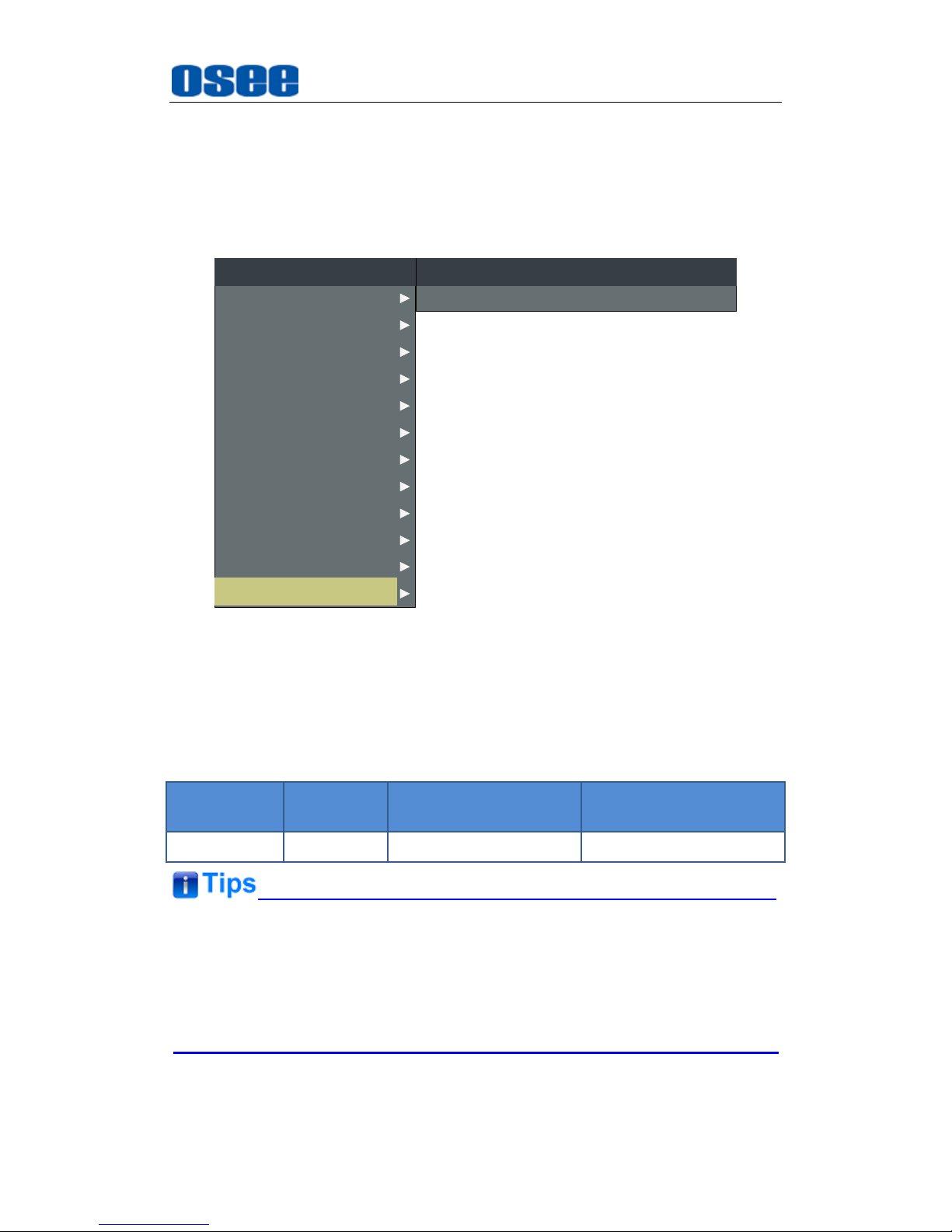
Functionality of the Main Menu
69
5.1.12 KEY INHIBIT Menu
The KEY INHIBIT menu item is used to lock the setting so that they can’t
be changed by an unauthorized user, and the menu item is as shown in
Figure 5.1-37:
AUDIO
CONFIG
COLOR TEMP
FUNCTION KEY
GPI
MAIN
CLOSED CAPTION
DISPALY
MARKER
INPUT SELECT
STATUS
IMD
KEY INHIBIT
KEY INHIBIT
KEY INHIBIT
OFF
Figure 5.1-37 KEY INHIBIT Menu
The relationship of Items, Default Value, Domain Range and Description
of the sub-item is shown in Table 5.1-7:
Table 5.1-19 The Description of KEY INHIBIT Menu Items
Items
Default
Value
Domain Range
Description
KEY INHIBIT
OFF
OFF/ON
Enable/Disable the key.
When the KEY INHIBIT is ON, KEY INHIBIT is enabled and press the
POWER key, the device would turn on or off. MENU, UP, DOWN, ENTER
key can be enable but only to set the KEY INHIBIT item, or there is a “KEY
INHIBIT” prompt displayed on the screen when using other keys.
Page 76
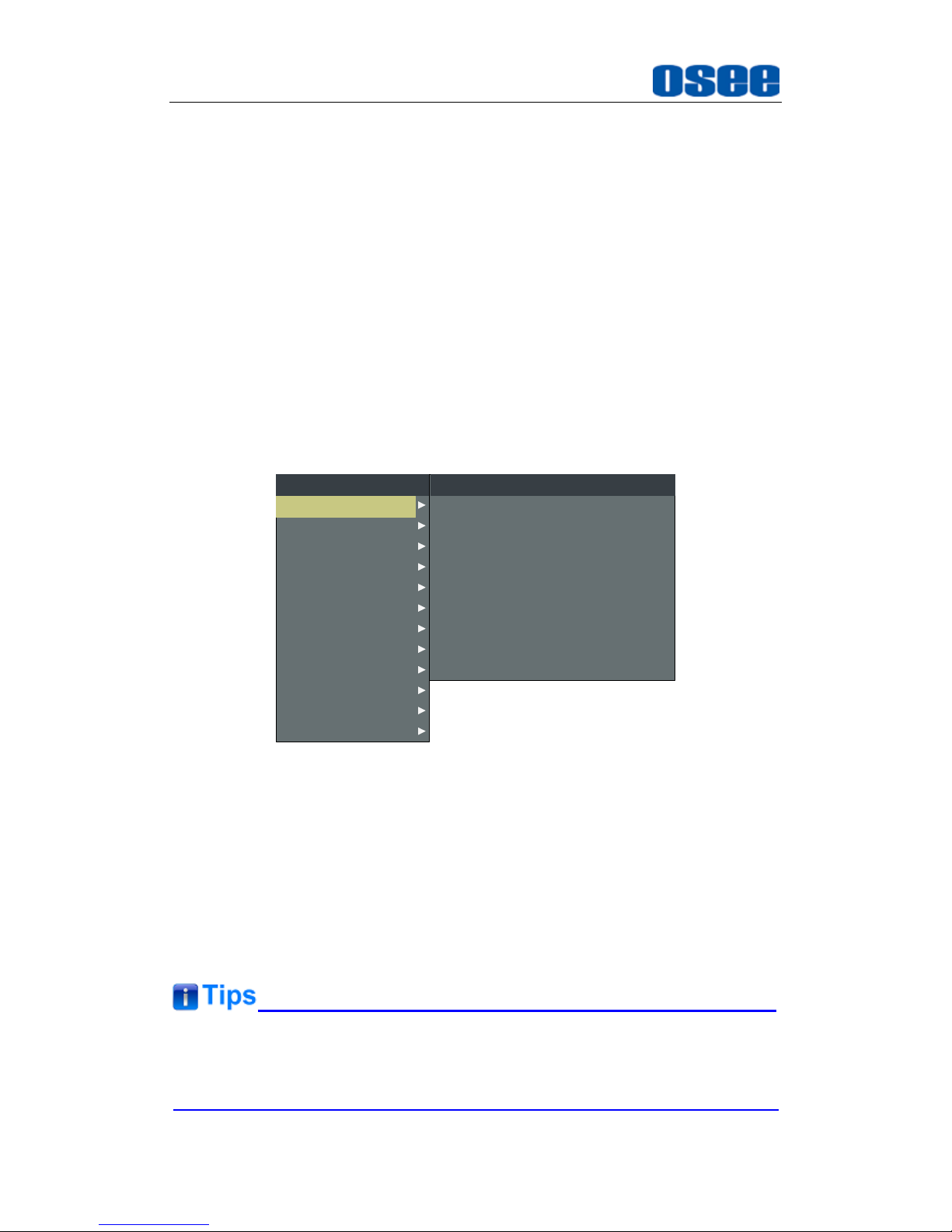
Functionality of the Main Menu
70
5.2 Menu Settings
When checking or modifying the value of the menu item, cooperating with the
following buttons: MENU, UP, DOWN, ENTER.
1. Operations to the Main menu
Display the Main Menu
Press MENU button to enter into the main menu, it displays at the top
left corner of the screen.
Switch menu items
After displaying the main menu, press UP or DOWN button to choose a
menu item, the menu item selected is in yellow. For example, you have
selected Status menu, as shown in Figure 5.2-1.
CLOSED CAPTION
INPUT SELECT
MARKER
AUDIO
DISPALY
CONFIG
COLOR TEMP
FUNCTION KEY
GPI
MAIN
MODEL
INPUT
FORMAT
COLOR TEMP
SCAN MODE
FAST MODE
SERIAL NUMBER
IP ADDRESS
COLOR VERSION
STATUS
XCM-250-3G
SDI1
NO SIGNAL
D65
OVER
OFF
XCM2502014070001
192.168.1.86
2015 -1 -5.4
STATUS
IMD
KEY INHIBIT
Figure 5.2-1 Selecting STATUS Menu
Back to the Main menu
After entering to a sub-menu item or a sub-menu item value, press
MENU button to back to the upper level menu area.
Close the Main menu
Press MENU button to close the Main menu when the control icon is in
the Main menu item.
After you have loaded the Main menu, it will be closed automatically if you
do nothing operation with it in 60s.
Page 77
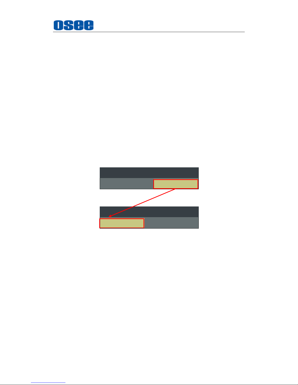
Functionality of the Main Menu
71
2. Operations to sub-menu item
Display the sub-menu item
After display the Main menu, press UP or DOWN button to select a
menu item, and the right part displays its sub-menu items according to
the current selected menu item.
Switch sub-menu items
After displaying the sub-menu items list, press ENTER button to enter
into the sub-menu items list, press UP or DOWN button to choose a
sub-menu item, a yellow rectangle is in front of the selected sub-menu
item.
Back to menu item
After entering to the sub-menu item value, press MENU button to back
to menu items, or after setting the sub-menu item value and press Enter
button to firm the modification, the control icon is back to the
corresponding sub-menu item, as shown in Figure 5.2-2:
OFF
INPUT SELECT
SDI1
INPUT SELECT
SDI1 OFF
Figure 5.2-2 The Control Icon Moves from the Sub-menu Item Value to
the Corresponding Sub-menu Item
3. Operations to sub-menu item value
Switch sub-menu item value
When the control icon is in sub-menu item value, press UP or DOWN
button to switch among its value list.
Confirm the modification to sub-menu item value
Press ENTER button to confirm the selection of a value, and the control
icon is back to the corresponding sub-menu item.
Abandon the modification to sub-menu item value
Press MENU button to give up the modification to sub-menu item value,
and the control icon is back to the corresponding sub-menu item.
Page 78
Functionality of the Main Menu
72
The value in white color is modifiable, and the value in blue color is
unmodifiable.
4. Selecting the Menu Language
You can select one of languages (English or Chinese) for displaying the
menu. The default language for the menu is ENGLISH. The following
will teach you how to switch to Chinese.
Operation:
Step 1 Select CONFIG menu
Press MENU button to display the OSD menu, click DOWN button to
select CONFIG menu.
Step 2 Select the value of the Language item
Press ENTER button to get into the CONFIG menu items, and click
DOWN button to select the sub-item LANGUAGE, then, click ENTER
button to get into the sub-value list, as shown in Figure 5.2-3, the
current control icon is in ENGLISH.
AUDIO
FUNCTION KEY
GPI
MAIN
CONFIG
COLOR TEMP
CLOSED CAPTION
DISPALY
MARKER
INPUT SELECT
STATUS
IMD
KEY INHIBIT
PIP POSITION
FAST MODE
FILM MODE DETECT
SUB IN TYPE
SUB IN SELECT
PIP SIZE
AUTO STANDBY
APPEATURE
CONFIG
HORIZONTAL
OFF
OFF
PBP
SDI1
LARGE
OFF
0
LOCK NUMBER 0
LANGUAGE ENGLISH
FLASH NUM
SDI ASSIST MODE
ONCE
OFF
SCREEN SAVER OFF
WIPE LINE DISPLAY WHITE
Figure 5.2-3 Select the Value of Language
Page 79
Functionality of the Main Menu
73
Step 3 Confirm the modification of the value of sub-item
Click DOWN button to select the sub-item LANGUAGE to Chinese, as
shown in Figure 5.2-4, press ENTER button to confirm the modification.
输入设置
显示设置
色彩配置
功能键设置
GPI设置
主菜单
系统配置
隐藏字幕
音频设置
标记设置
状态显示
IMD设置
按键锁定
PIP位置
快速模式
电影模式检测
子画面类型
子画面输入源
PIP大小
自动关机
清晰度
系统配置
右下
关闭
关闭
PBP
SDI1
小
关闭
0
授权码
0
语言 中文
闪烁次数
SDI辅助模式
一次
关闭
屏幕保护 关闭
划像线显示 白色
Figure 5.2-4 Switching the Value of LANGUAGE
Step 4 Exit the main menu
Click MENU button to exit the main menu.
Page 80

74
Page 81
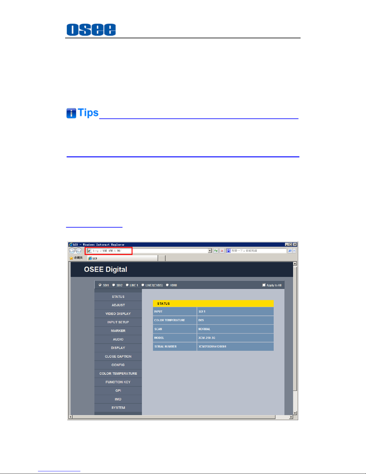
Network Control
75
Chapter 6 Network Control
XCM-250 supports network interface. Connect a computer with XCM-250
through this interface to achieve the network control to XCM-250.
The network address of the computer which is connected with XCM-250
and the network address of XCM-250 must be in the same segment.
This chapter will introduce how to set and check the parameters of XCM-250 in
Internet Explorer.
6.1 Access the settings
Use Internet Explorer to enter into a web control page. For example, input
http://192.168.1.86 in address bar, it will display the then, press Enter key, the
management interface of XCM-250 is shown as in Figure 6.1-1:
Figure 6.1-1 Network Control Page
Page 82
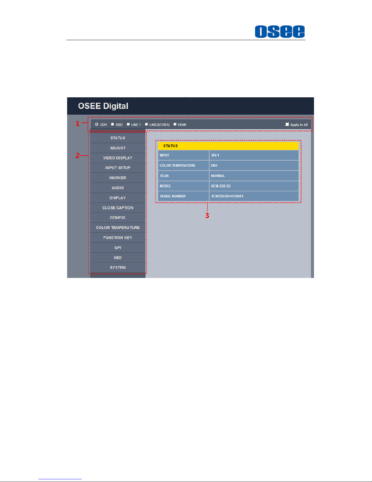
Network Control
76
6.2 Menu Control
Open the management interface as shown in Figure 6.2-1, the menu items
listed in the left part are almost as the same as the main menu items.
Figure 6.2-1 Management Interface
As shown in Figure 6.2-1, the management interface is divided into the
following parts:
1. Input Source Selection Button
It is used to selecting an input source as the input signal, such as: SDI1,
SDI2, LINE1, LINE2(CVBS), HDMI. The selecting box of "Apply to All" at
the right side is used to synchronize the settings for all the other kinds of
input sources.
2. Navigation menu list
It shows the navigation menus: STATUS, ADJUST, VIDEO DISPLAY,
INPUT SETUP, MARKER, AUDIO, DISPLAY, CLOSE CAPTION,
CONFIG, COLOR TEMPERATURE, FUNCTION KEY, GPI, IMD and
SYSTEM. Click the navigation menu, it will show the corresponding
settings on the right side. The menu items in main menu on screen
Page 83
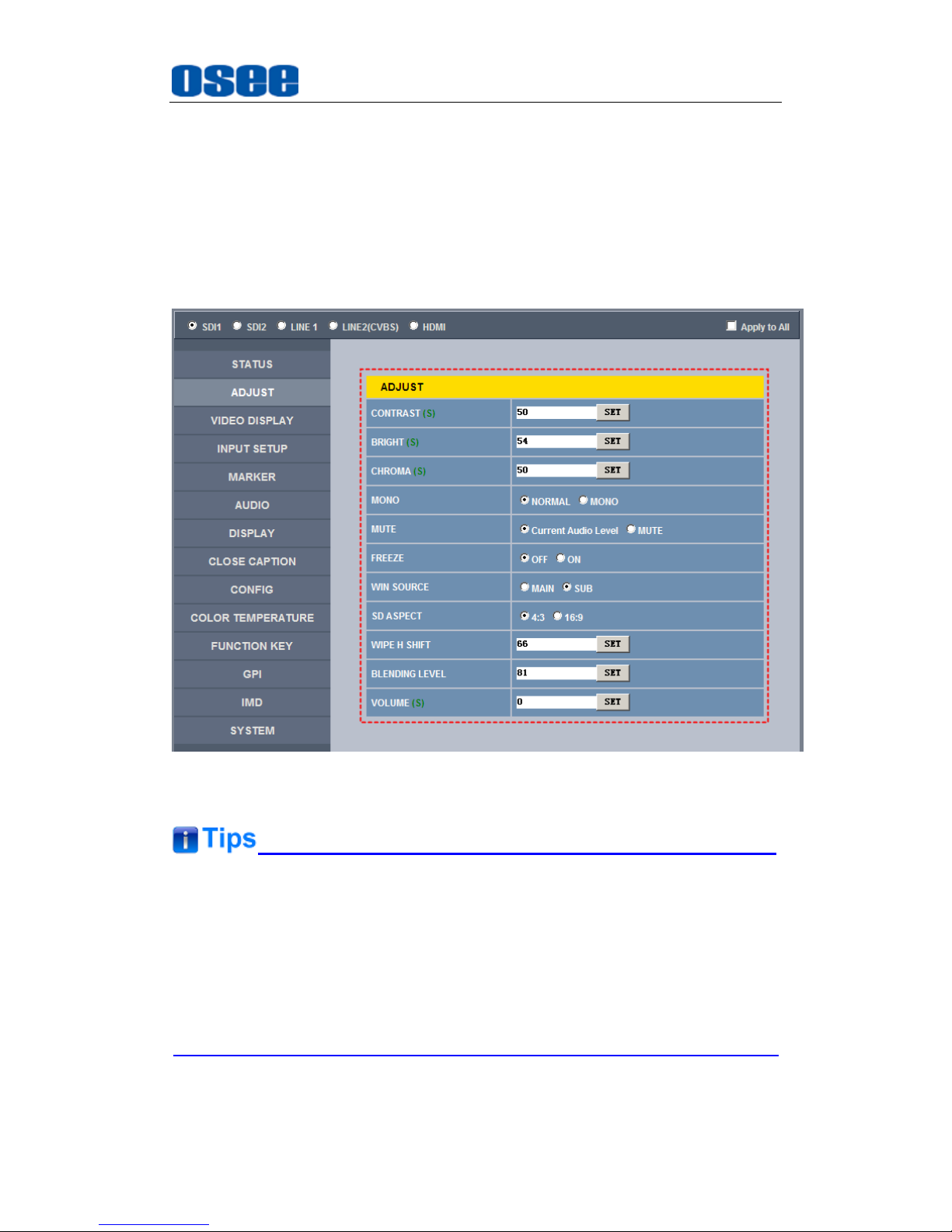
Network Control
77
display are mostly as the same as the menu items listed in navigation
menus except SYSTEM, ADJUST and VIDEO DISPLAY.
3. Parameter list
It shows the parameter names, values and operation buttons of the
selected navigation menu, as shown in the red rectangle in Figure 6.2-2.
The title in the yellow rectangle of the parameter list and the parameter
list will change with the navigation menu when switched.
Figure 6.2-2 Parameter List
There may be a “(S)” icon followed by some parameter name in the
parameter list, it is mean that this parameter is only a local parameter for
the current selected signal source, otherwise, the parameter is global and
the modification is valid for all signal sources.
The
SET
button is used to confirm the modification of the parameter value.
Page 84
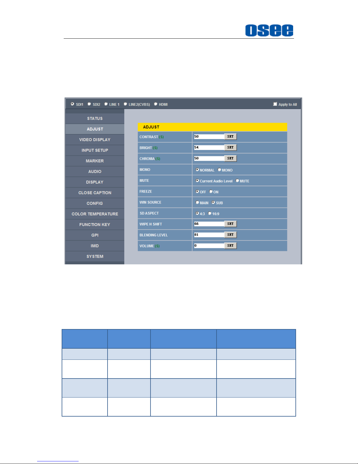
Network Control
78
6.2.1 ADJUST Menu
It will introduce ADJUST menu.
Click
ADJUST
button at the left navigation menu list, it will display the
adjust parameters, as shown in Figure 6.2-3:
Figure 6.2-3 ADJUST Menu
The relationship of Items, Default Value, Domain Range and Description
of the sub-item is shown in Table 6.2-1:
Table 6.2-1 The Description of ADJUST Menu Items
Items
Default
Value
Domain Range
Description
CONTRAST
50
0~100
Adjust the picture contrast
BRIGHTNES
S
50
0~100
Adjust the picture
brightness
CHROMA
50
0~100
Adjust the picture
monochroma
MONO
NORMAL
NORMAL/MONO
Enable/disable
Monochrome mode,
Page 85
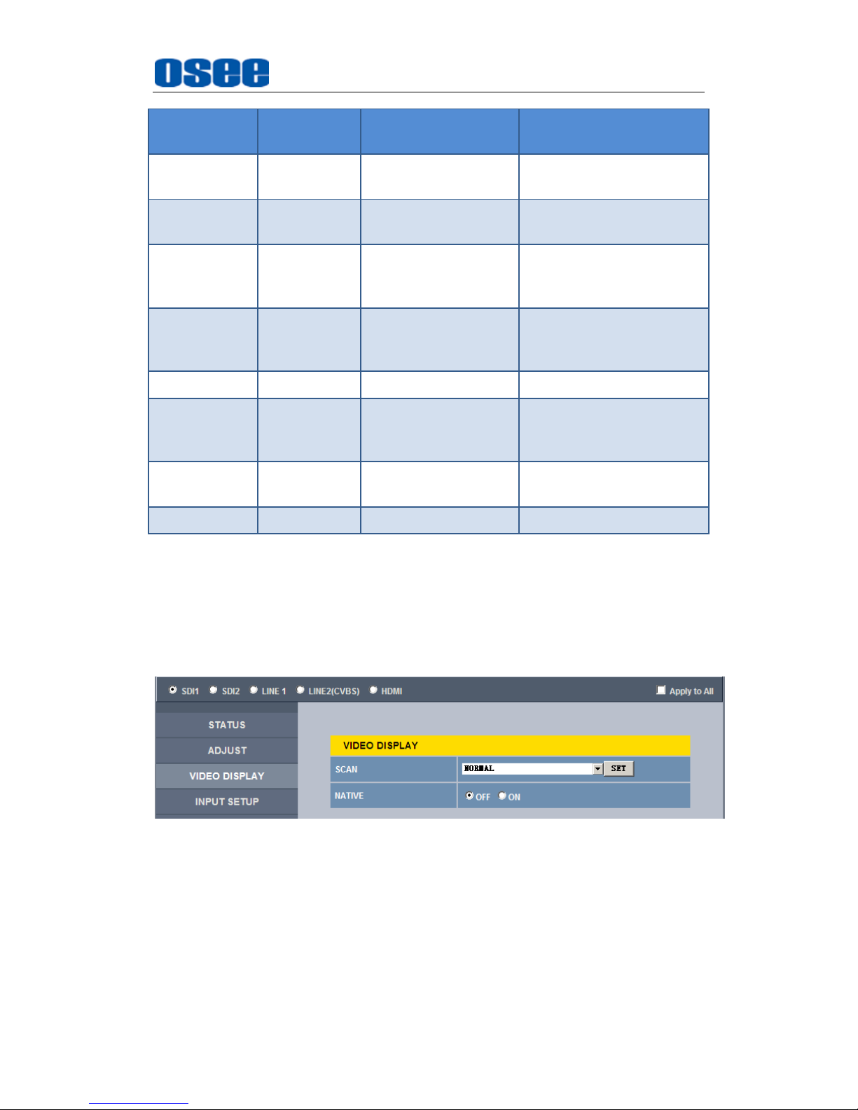
Network Control
79
Items
Default
Value
Domain Range
Description
normal mode is actually
the color mode
MUTE
Current
Audio Level
Current Audio Level
/MUTE
Enable/disable the audio
monitor
FREEZE
OFF
OFF/ON
Enable/disable the
current picture to be
stopped or played.
WIN
SOURCE
MAIN
MAIN/SUB
Set the picture displaying
mode in full mode or in
sub-picture mode.
HD ASPECT
16:9
2.39:1/16:9
Set the aspect ratio
WIPE H
SHIFT
0
-64~64
Set the wipe line position
according to the wipe
ratio.
BLENDING
LEVEL
0
-64~64
Set the blending ratio.
VOLUME
16
0~31
Adjust the volume
6.2.2 VIDEO DISPLAY Menu
It will introduce VIDEO DISPLAY menu.
Click
VIDEO DISPLAY
button at the left navigation menu list, it will display
the video display parameters, as shown in Figure 6.2-4:
Figure 6.2-4 VIDEO DISPLAY Menu
The relationship of Items, Default Value, Domain Range and Description of the
sub-item is shown in
Table 6.2-2:
Page 86
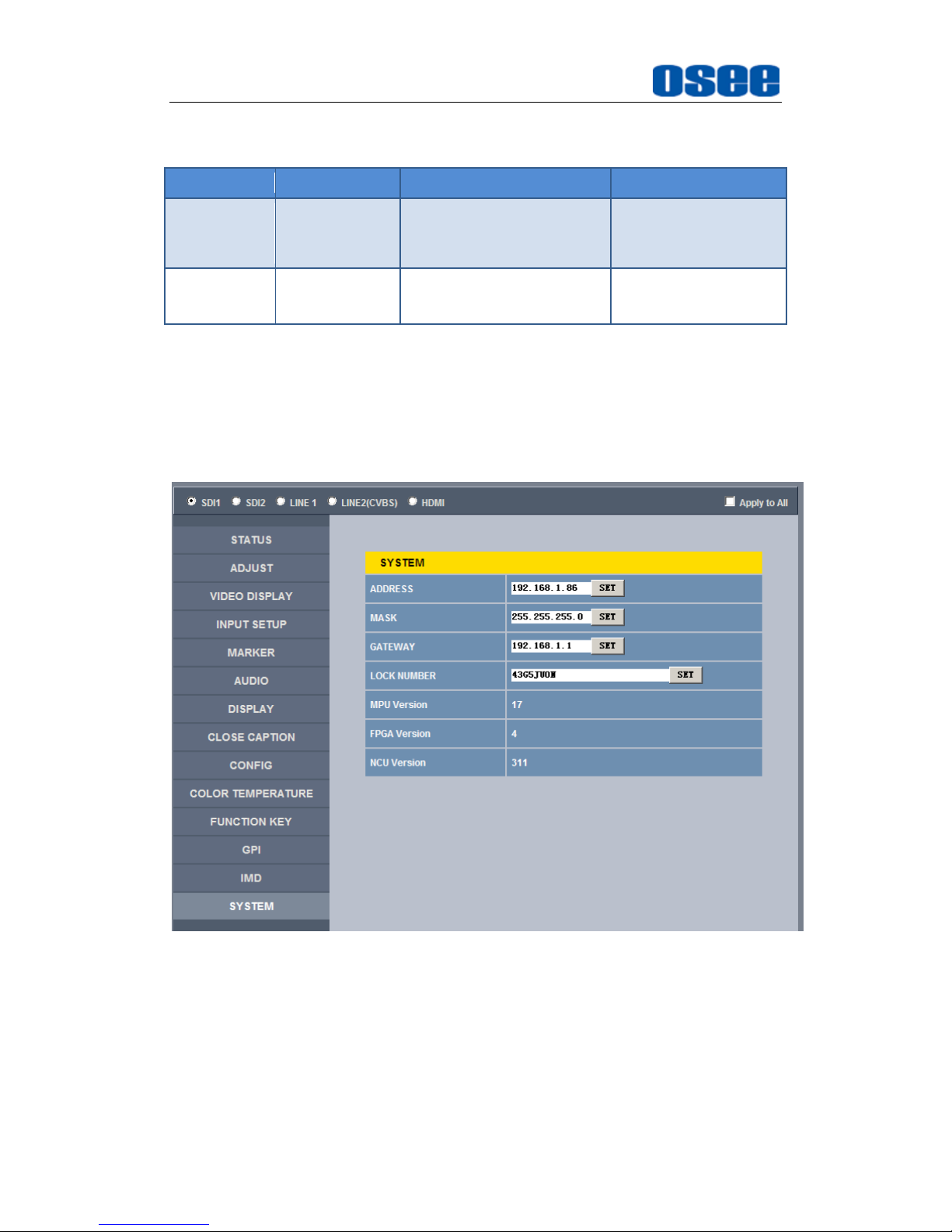
Network Control
80
Table 6.2-2 The Description of VIDEO DISPLAY Menu Items
Items
Default Value
Domain Range
Description
SCAN
NORMAL
NORMAL
OVERSCAN
UNDERSCAN
Set the scan mode
NATIVE
OFF
OFF/ON
Whether to display
the picture dot by dot
6.2.3 SYSTEM Menu
It will introduce SYSTEM menu.
Click
SYSTEM
button at the left navigation menu list, it will display the
system parameters, as shown in Figure 6.2-5:
Figure 6.2-5 System Menu
The relationship of Items, Default Value, Domain Range and Description
of the sub-item is shown in Table 6.2-3:
Page 87
Network Control
81
Table 6.2-3 The Description of System Menu Items
Items
Default Value
Domain
Range
Description
IP 192.168.1.86
-
IP address
MASK
255.255.255.0
- Subnet mask
Gateway
192.168.1.1
- Gateway address
LOCK NUMBER
XXXXXX
- Set the Serial Number
MPU Version
17
-
Product information
FPGA Version
4
-
Product information
NCU Version
311
-
Product information
6.2.4 Other Menus
For the menu items in management interface are almost as the same as
the menu items in the Main menu on screen, there will be no further
description about their meanings and value range in this chapter, refer to
“Chapter 5 Functionality of the Main Menu” for the details about
STATUS
,
VIDEO CONFIG, AUDIO CONFIG, MARKER, DISPLAY, USER CONFIG
,
COLOR TEMPERATURE
and so on.
6.3 Parameter Settings
It will introduce how to modify parameter values in management interface in
the followings.
For example: modify Meter Select in AUDIO menu. Click AUDIO button to
display its parameter list, as shown in Figure 6.3-1, the corresponding screen
main menu is shown as in Figure 6.3-2:
Page 88
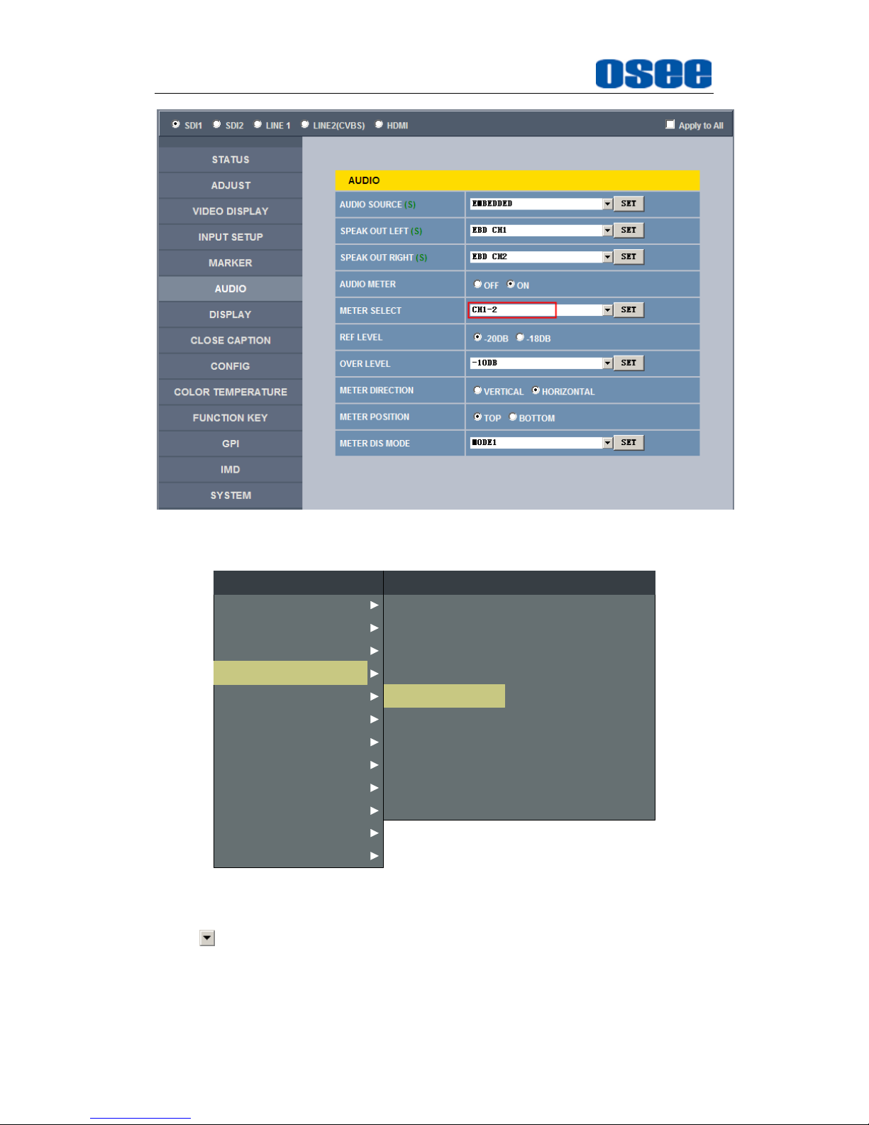
Network Control
82
Figure 6.3-1 Parameter List for AUDIO
CLOSED CAPTION
DISPALY
CONFIG
COLOR TEMP
FUNCTION KEY
GPI
MAIN
AUDIO
MARKER
INPUT SELECT
STATUS
IMD
KEY INHIBIT
METER DIRECTION
AUDIO SOURCE
SPEAK OUT L
SPEAK OUT R
AUDIO METER
METER SELECT
METER POSITION
METER DIS MODE
REF LEVEL
AUDIO
HORIZONTAL
AUDIO1
EBD CH1
EBD CH1
OFF
CH1-2
TOP
MODE1
-20dB
OVER LEVEL -10dB
Figure 6.3-2 Screen Main Menu for AUDIO
Click button to display the drop-down value list for the parameter, as shown
in Figure 6.3-3, for example, modify “CH1-2” to “G1”.
Page 89
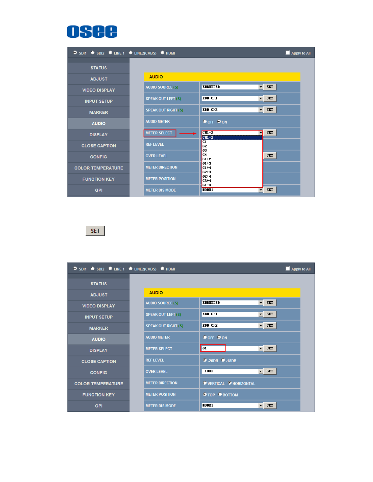
Network Control
83
Figure 6.3-3 Display the Drop Down Value List of Meter Select(S)
Click button to confirm the selection and the page is refreshed. You
can check the modification on the screen menu, the results are the same as
shown in Figure 6.3-4 and Figure 6.3-5:
Figure 6.3-4 Modify the Value of a Parameter
Page 90
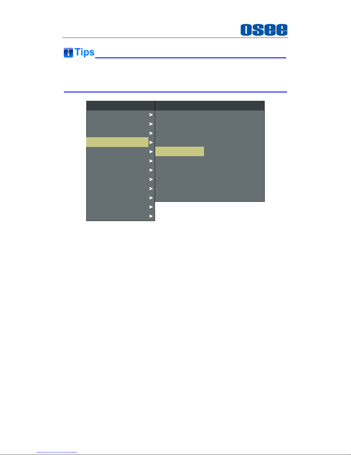
Network Control
84
The volume can be checked and modified in adjust menu on screen
adjustment, or in
Volume
item of
ADJUST
menu in management interface.
CLOSED CAPTION
DISPALY
CONFIG
COLOR TEMP
FUNCTION KEY
GPI
MAIN
AUDIO
MARKER
INPUT SELECT
STATUS
IMD
KEY INHIBIT
METER DIRECTION
AUDIO SOURCE
SPEAK OUT L
SPEAK OUT R
AUDIO METER
METER SELECT
METER POSITION
METER DIS MODE
REF LEVEL
AUDIO
HORIZONTAL
AUDIO1
EBD CH1
EBD CH1
OFF
G1
TOP
MODE1
-20dB
OVER LEVEL -10dB
Figure 6.3-5 The Value is Modified Simultaneously on Screen Menu
Likewise, if you modify the value of a parameter on screen menu first, you may
check the same changing result in management interface through network
connection.
Page 91
Specifications
85
Chapter 7 Specifications
1. Product detailed information
Specification
Values
Picture performance
Picture size (Diagonal)
24.5”
Screen Dimension
580(H) x 404(V) x 57.7(D)
Aspect Ratio
16:9
Display Area(mm)
543.36(H)×305.64(V)
Viewing Angle
178°(H)x178°(V)
Color Depth
1.073G colors (RGB 10-bits)
Resolution
1920(H)×1080(V)
Pixel Pitch(mm)
0.283(H)×0.283(V)
Pixel Efficiency
99.99%
Panel Frame Rate
48Hz, 50Hz, 60Hz
Standard Luminance
100 cd/㎡(100% white signal input)
Color Temperature
D55/D61/D65/ D93/User Defined
Color Space
ITU-R BT.709/EBU/SMPTE-C/D-Cine
Interface Characteristic
Video Input Interface
CVBS, YPbPr, 3G/HD/SD-SDI, HDMI
Video Output Interface
CVBS, YPbPr, 3G/HD/SD-SDI
Audio Input Interface
2CH analog stereo, 5dBu , Impedance≥47K,
RCA(X4)
Audio Output Interface
1CH analog stereo, 5dBu, Impedance≤500Ω,
RCA(X2)
Audio Output Interface
Headphone output (mini jack 3.5mm)
Control Interface
GPI(6GPI input RJ45)X1
RS485(Cascade RJ45) X2
Ethernet(10/100M adaptive RJ45) X1
Signal Standard
SMPTE 424M, SMPTE 292M, SMPTE 259M,
SMPTE 297M, SMPTE ST 2048-2
SDI Connector
BNC per IEC 169-8
Page 92
Specifications
86
Specification
Values
Input/Output Impedance
SDI 75Ω(unbalanced)
LINE 75Ω(loop-through, with automatic termination)
SDI Transmission Distance
3G –SDI: 70m (max.)
HD –SDI: 100m (max.)
SD-SDI: 200m (max.)
Differential Phase
<1.5°
General
Power Adapter
Input: AC 100~240V/50/60Hz
Output: DC 24V 6.67A
Power Consumption
Approx.120W (max.)/ Approx.65W(avg.)
Operating Temperature
0°C~35°C
Operating Humidity
0%~90% (no condensation)
Storage Temperature
-20°C~60°C
Storage Humidity
0%~90%
Operating Pressure
Lower than 2000 meter(above sea level)
2. Input/Output Resolution, Aspect Ratio and Native
Input Signal
ASPECT
RATIO
NORMAL SCAN
OVER SCAN
UNDER SCAN
NATIVE
Input
Output
Input
Output
Input
Output
Input
PAL
4:3
720X576
1440x1080
684x547
1440x1080
720X576
1368X1026
720X576
16:9
1920X1080
1920X1080
1824X1026
NTSC
4:3
720X483
1440x1080
684x458
1440x1080
720X483
1368X1026
720X483
16:9
1920X1080
1920X1080
1824X1026
480I60/59.94
4:3
720X483
1440x1080
684x458
1440x1080
720X483
1368X1026
720X483
16:9
1920X1080
1920X1080
1824X1026
576I50
4:3
720X576
1440x1080
684x547
1440x1080
720X576
1368X1026
720X576
16:9
1920X1080
1920X1080
1824X1026
480P60/59.94
4:3
720X483
1440x1080
684x458
1440x1080
720X483
1368X1026
720X483
16:9
1920X1080
1920X1080
1824X1026
576P50
4:3
720X576
1440x1080
684x547
1440x1080
720X576
1368X1026
720X576
16:9
1920X1080
1920X1080
1824X1026
720P24/23.97
16:9
1280X720
1920X1080
1216X684
1920X1080
1280X720
1824X1026
1280X720
2.39:1
1920X803
1920X803
1824X763
720P25
16:9
1280X720
1920X1080
1216X684
1920X1080
1280X720
1824X1026
1280X720
2.39:1
1920X803
1920X803
1824X763
Page 93
Specifications
87
Input Signal
ASPECT
RATIO
NORMAL SCAN
OVER SCAN
UNDER SCAN
NATIVE
Input
Output
Input
Output
Input
Output
Input
720P30/29.97
16:9
1280X720
1920X1080
1216X684
1920X1080
1280X720
1824X1026
1280X720
2.39:1
1920X803
1920X803
1824X763
720P50
16:9
1280X720
1920X1080
1216X684
1920X1080
1280X720
1824X1026
1280X720
2.39:1
1920X803
1920X803
1824X763
720P60/59.94
16:9
1280X720
1920X1080
1216X684
1920X1080
1280X720
1824X1026
1280X720
2.39:1
1920X803
1920X803
1824X763
1080SF24/23.
97
16:9
1920X1080
1920X1080
1824X1026
1920X1080
1920X1080
1824X1026
1920X1080
2.39:1
1920X803
1920X803
1824X763
1035I60/59.94
16:9
1920X1080
1920X1080
1824X1026
1920X1080
1920X1080
1824X1026
1920X1035
2.39:1
1920X803
1920X803
1824X763
1080I50
16:9
1920X1080
1920X1080
1824X1026
1920X1080
1920X1080
1824X1026
1920X1080
2.39:1
1920X803
1920X803
1824X763
1080I60/59.94
16:9
1920X1080
1920X1080
1824X1026
1920X1080
1920X1080
1824X1026
1920X1080
2.39:1
1920X803
1920X803
1824X763
1080P24/23.9
7
16:9
1920X1080
1920X1080
1824X1026
1920X1080
1920X1080
1824X1026
1920X1080
2.39:1
1920X803
1920X803
1824X763
1080P25
16:9
1920X1080
1920X1080
1824X1026
1920X1080
1920X1080
1824X1026
1920X1080
2.39:1
1920X803
1920X803
1824X763
1080P30/29.9
7
16:9
1920X1080
1920X1080
1824X1026
1920X1080
1920X1080
1824X1026
1920X1080
2.39:1
1920X803
1920X803
1824X763
1080P50
16:9
1920X1080
1920X1080
1824X1026
1920X1080
1920X1080
1824X1026
1920X1080
2.39:1
1920X803
1920X803
1824X763
1080P60/59.9
4
16:9
1920X1080
1920X1080
1824X1026
1920X1080
1920X1080
1824X1026
1920X1080
2.39:1
1920X803
1920X803
1824X763
2048X1080PS
F24/23.97
1.896:1
2048X1080
1920X1013
1946X1026
1920X1013
2048X1080
1824X962
2048X1080
2.39:1
1920X803
1920X803
1824X763
2048X1080PS
F25
1.896:1
2048X1080
1920X1013
1946X1026
1920X1013
2048X1080
1824X962
2048X1080
2.39:1
1920X803
1920X803
1824X763
2048X1080PS
F30/29.97
1.896:1
2048X1080
1920X1013
1946X1026
1920X1013
2048X1080
1824X962
2048X1080
2.39:1
1920X803
1920X803
1824X763
2048X1080P2
4/23.97
1.896:1
2048X1080
1920X1013
1946X1026
1920X1013
2048X1080
1824X962
2048X1080
2.39:1
1920X803
1920X803
1824X763
2048X1080P2
5
1.896:1
2048X1080
1920X1013
1946X1026
1920X1013
2048X1080
1824X962
2048X1080
2.39:1
1920X803
1920X803
1824X763
2048X1080P3
1.896:1
2048X1080
1920X1013
1946X1026
1920X1013
2048X1080
1824X962
2048X1080
Page 94
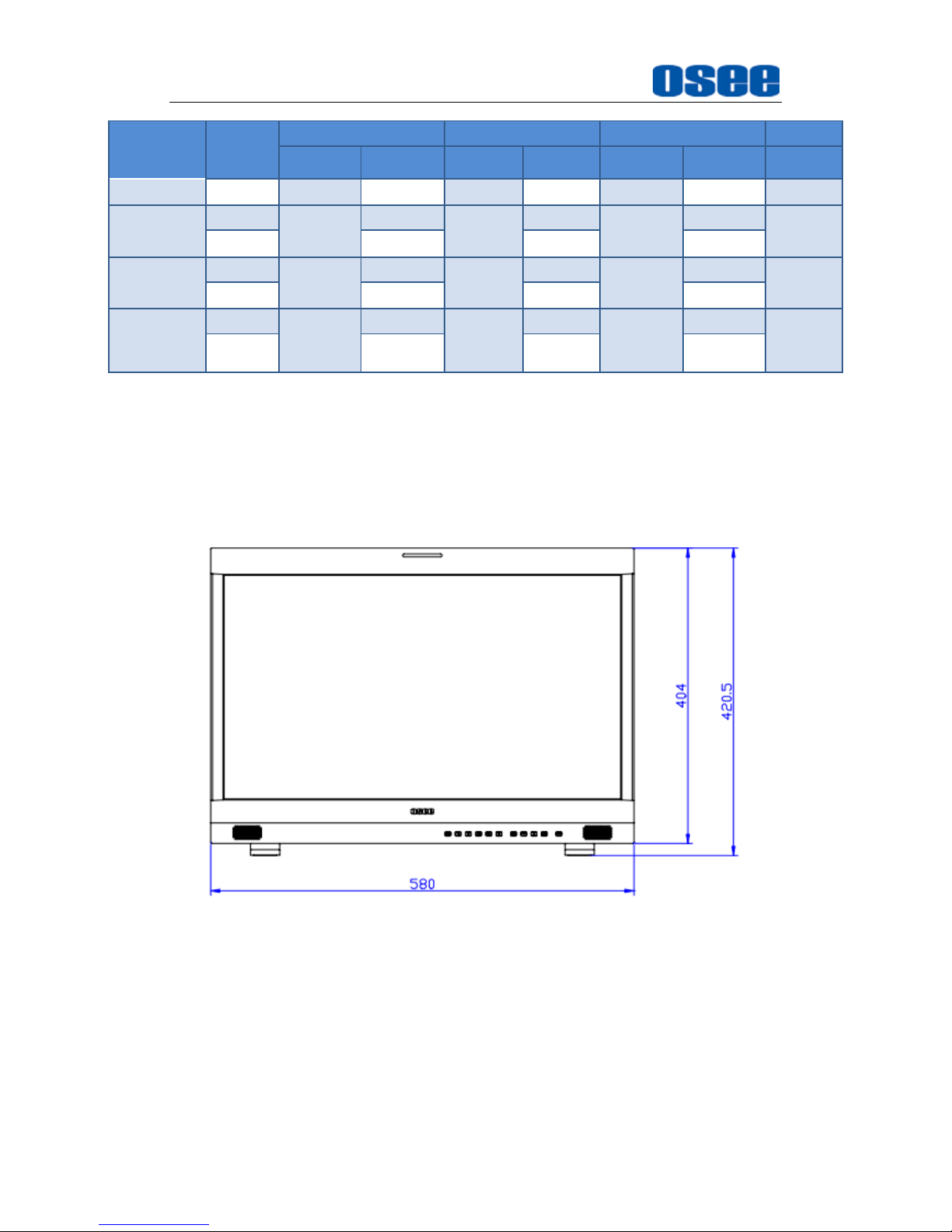
Specifications
88
Input Signal
ASPECT
RATIO
NORMAL SCAN
OVER SCAN
UNDER SCAN
NATIVE
Input
Output
Input
Output
Input
Output
Input
0/29.97
2.39:1
1920X803
1920X803
1824X763
2048X1080P4
8/47.94
1.896:1
2048X1080
1920X1013
1946X1026
1920X1013
2048X1080
1824X962
2048X1080
2.39:1
1920X803
1920X803
1824X763
2048X1080P5
0
1.896:1
2048X1080
1920X1013
1946X1026
1920X1013
2048X1080
1824X962
2048X1080
2.39:1
1920X803
1920X803
1824X763
2048X1080P6
0/59.94
1.896:1
2048X1080
1920X1013
1946X1026
1920X1013
2048X1080
1824X962
2048X1080
2.39:1
1920X803
1920X803
1824X763
*Don’t display all OSD when SCAN is NATIVE.
*Don’t display MARKER when SCAN is NATIVE.
3. Dimensions
The description of the product dimensions is shown as in the following
figures:
Figure 7-1 Front Panel(Unit: mm)
Page 95
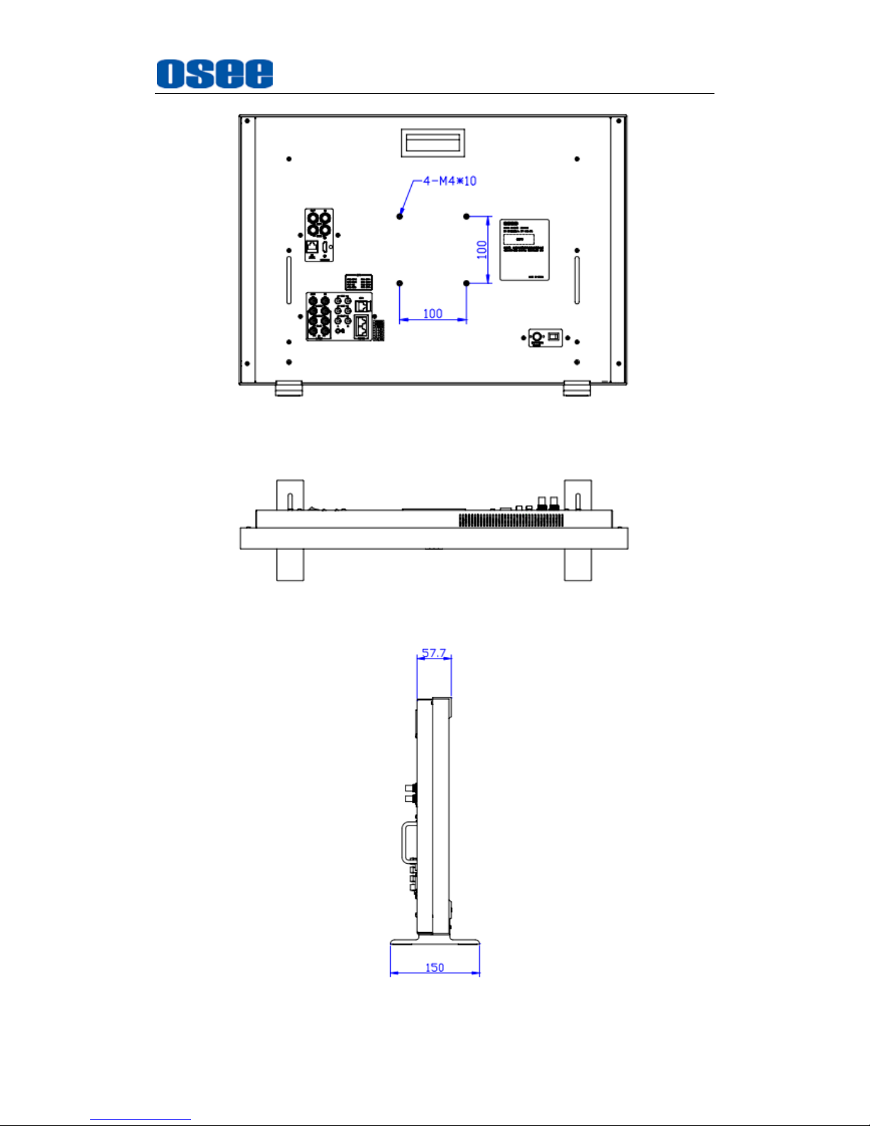
Specifications
89
Figure 7-2 Rear Panel(Unit: mm)
Figure 7-3 Top View(Unit: mm)
Figure 7-4 Side View(Unit: mm)
Page 96
Specifications
90
Specifications are subject to change without notice.
------------------No Text Below------------------
Page 97

FOR MORE INFORMATION PLEASE VISIT: http://www.osee-dig.com/
OSEE TECHNOLOGY CO., LTD.
Address:
No.22 Building, No.68 zone, Beiqing Road, Haidian District,
Beijing, China
Tel:
(+86) 010-62434168
Fax:
(+86) 010-62434169
OSEE AMERICAS, LTD.
Address:
43218 Christy Street Fremont, CA 94368
Toll Free:
866-625-6106
Tel:
(+1) 510-966-4499
Fax:
(+1) 510-966-4492
E-mail: [email protected]
 Loading...