

OSEE VAM6800 User Manual

VAM6800 A/D Conversion
and Audio Embedder
USER MANUAL

Product Information
Model:
VAM6800 A/D Conversion and Audio Embedder
Version:
V010002
Release Date:
July 19th, 2010
Company
OSEE TECHNOLOGY CO., LTD.
Contact Information
Address:
No.22 Building, No.68 zone, Beiqing Road, Haidian District,
Beijing, China
Post Code:
100094
Tel:
(+86) 010-62434168
Fax:
(+86) 010-62434169
Web:
http://www.osee-dig.com/
E-mail:
sales@osee-dig.com

Contents
Chapter 1 Introduction ............................................................................................ 4
Overview ............................................................................................................................................ 4
General Description ........................................................................................................................... 4
Features .............................................................................................................................................. 4
Module Descriptions .......................................................................................................................... 6
The Front Part of the Module ..................................................................................................... 6
Back Connector .................................................................................................................................. 6
V AM6800 ................................................................................................................................... 6
VAM6800S ................................................................................................................................. 7
Signal Flow ........................................................................................................................................ 8
Chapter 2 Installation .............................................................................................. 8
Overview ............................................................................................................................................ 8
Maximum Power Ratings for Frame .................................................................................................. 9
Unpacking the Module ....................................................................................................................... 9
Preparing the Product for Installation ........................................................................................ 9
Check the Packing List............................................................................................................... 9
Installing the Module ......................................................................................................................... 9
Making the Connections .................................................................................................................. 10
Removing the Module ...................................................................................................................... 10
Setting Jumper................................................................................................................................... 11
Chapter 3 Operation and Control .......................................................................... 12
Switches and Key ............................................................................................................................. 12
Instructions on LED ......................................................................................................................... 15
Chapter 4 Specifications ....................................................................................... 15
Composite V i deo Input .................................................................................................................... 15
Composite V i deo Output .................................................................................................................. 16
Analog Audio Input .......................................................................................................................... 16
Warranty for osee product ................................................................................... 17
What the warranty covers: ............................................................................................................... 17
What the warranty does not cover: ................................................................................................... 17

VAM6800 A/D Conversion and Audio Embedder - 4 -
Chapter 1 Introduction
Overview
In this manual, the analog video module and audio embedder module for VAM6800 are introduced.
The modules for VAM6800 include decoder and line buffer that can remove the jitter, one analog video
input, two balanced analog audio inputs and three SDI outputs with embedded audio.
The VAM6800S has one analog video input, one analog reference input, two balanced analog audio
inputs and three SDI outputs with embedded audio. In addition to the functions that VAM6800 provides,
the VAM6800S also features in frame synchronizer and can synchronize to the external reference signal.
The system synchronization must be in consistency with the standard of analog composite input,
otherwise the VAM6800S cannot work properly. It prefers BB signal as system synchronization and it
must comply with standard of analog composite signal.
The VAM6800 can be housed in 6800N series frame.
General Description
The VAM6800 is a decoder and audio embedder with broadcast quality. It converts analog composite
NTSC/PAL signal and analog audio signal into SDI component signal with embedded audio. The
VAM6800 can be used in the broadcast and production system, where converting analog composite
video and audio signal into SDI component signal with embedded audio is required.
The VAM6800 incorporates the latest technology in circuit design and low power dissipation. Each card
can complete a variety of functions, such as the conversion between A/D, frame synchronization and
embedded audio. The VAM6800 can output three SDI component signals (SMPTE-259M)
simultaneously. The VAM6800 provides multi-function on card-edge.
The VAM6800 analog video and audio embedder can be controlled via the switches on the front panel.
Table 1-1 is the description for different modules.
Table 1-1 VAM6800 Analog V ideo/Audio Embedder
Module Description
VAM6800 Analog audio embedder, with three SDI outputs with embedded audio.
VAM6800S Analog audio embedder, with three SDI outputs with embedded audio,
and frame synchronizer.
Features
Compact Design
The VAM6800 includes 12-bit A/D conversion, 4X oversampling, digital decoding, frame
synchronization, conversion between parallel and serial, external synchronization, audio
embedding and all circuits. No extra circuit cards are needed for VAM6800S. Owing to the

VAM6800 A/D Conversion and Audio Embedder - 5 -
low power dissipation, 6800N series frame can house up to 10 pieces of VAM6800 cards.
Application in Multi-Standard
The VAM6800 can work in both 525 and 625 standards, and auto sensing on standards can
be achieved.
Advance Decoding
High performance is secured by adopting 12-bit decoding. The full digital processing in
signal and luminance decoding ensures the precision of decoding, and thus no more
readjustments are needed, and system can work in high reliability for long hours. In the
meantime, digital decoding allows to adopt 5-line adaptive comb filter, thus effects on
separating chrominance and luminance of analog composite signal can be secured.
Advanced Built-In Technology
The VAM6800 adopts 4X oversampling and built-in filter to guarantee better frequency
response, high signal noise ratio and low distortion.
Frame Synchronizer
The built-in frame synchronizer of VAM6800 can solve the synchronizing and timing issues
of the system, and can provide frame freeze as well.
Fully Functioned Processing Amplifier
The VAM6800 provides fully functioned processing amplifier to achieve the adjustment on
luminance level, black level, chrominance lev el an d Hue.
SETUP Control
Working in the 525 standard, the VAM6800 can control SETUP.
Synchronization
The VAM6800S can set the H-phase and V-phase.
FCC Caution:
Any Changes or modifications not expressly approved by the party responsible for compliance could
void the user's authority to operate the equipment.
This device complies with part 15 of the FCC Rules.
Operation is subject to the following two conditions: (1) This device may not cause harmful interference,
and (2) this device must accept any interference received, including interference that may cause
undesired operation.
Note: This equipment has been tested and found to comply with the limits for a Class B digital device,
pursuant to part 15 of the FCC Rules. These limits are designed to provide reasonable protection against
harmful interference in a residential installation. This equipment generates uses and can radiate radio
frequency energy and, if not installed and used in accordance with the instructions, may cause harmful
interference to radio communications. However, there is no guarantee that interference will not occur in
a particular installation. If this equipment does cause harmful interference to radio or television
reception, which can be determined by turning the equipment off and on, the user is encouraged to try to
correct the interference by one or more of the following measures:
Reorient or relocate the receiving antenna.
VAM6800 A/D Conversion and Audio Embedder - 6 -
Increase the separation between the equipment and receiver.
Connect the equipment into an outlet on a circuit different from that to which the receiver is connected.
Consult the dealer or an experienced radio/TV technician for help.
Module Descriptions
The Front Part of the Module
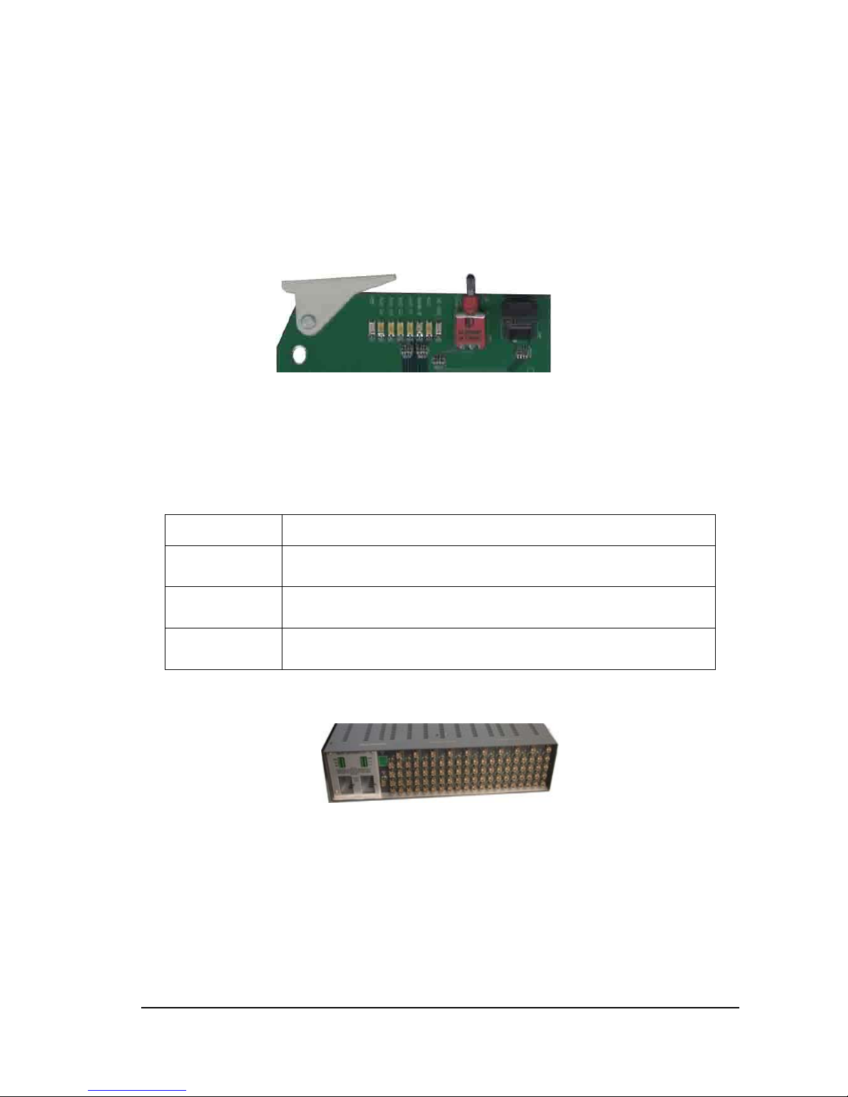
Figure 1-1 shows control switches and module status LEDs for VAM6800
Figure 1-1 Control Switches and Module Status LEDs for VAM6800
Table 1-1 briefly describes control switches and module status LEDs. Refer to chapter three for more
information on control switches and module status LEDs.
Table 1-1 VAM6800 Module Features
Feature Description
Module status
LEDs
Different colors and lighting combinations of these LEDs indicate the
module state. See “Instruction on LEDs” in chapter 3 for more information.
Mode select rotary
switch (SW1)
The SW1 is a rotary switch with 16 locations and used to select specific
settings.
Navigation toggle
switch (SW2)
The SW2 is a navigation toggle switch with 3 positions having auto
performance back to the middle location.
Back Connector
VAM6800
Figure 1-2 and Table 1-2 show the back connector for VAM6800.
 Loading...