

Page 1

RMD4342
USER MANUAL
Page 2
PRODUCT INFORMATION
MODEL: RMD4342 LCD MONITOR
Version: V040001
Release Date: 2010-3-11
COMPANY NAME
Beijing Osee Digital Technology Ltd.
CONTACT INFORMATION
Address: Room 702, Tower D, Jinyujiahua Building, No.9, 3rd Shangdi Street, Haidian
District, Beijing, China
Post code:100085
Tel: 8610-62968823
Fax: 8610-62977165
Http://www.osee-dig.com
E-mail:[email protected]
Page 3

About The USER MANUAL
The user manual applies to the following device types:
RMD4342-HSC
RMD4342-SC
RMD4342-V
The images of RMD4342-HSC are adopted in the following descriptions. Any of the
different specifications between the device types are elaborated. Before reading the manual,
please confirm the device type.
Page 4

Contents
Chapter 1 Product Overview .............................................................................................. 1
Chapter 2 Safety Precaution for Use .................................................................................. 2
Chapter 3 Unpacking and Installation ............................................................................... 3
Chapter 4 Using the RMD4342 ........................................................................................... 4
4.1 Status Display of the Screen .......................................................................................................... 4
4.2 Front Panel Controls ...................................................................................................................... 5
4.3 Quick Button Descriptions ............................................................................................................ 7
4.3.1 ENTER BUTTON ............................................................................................................ 7
4.3.2 USER BUTTON ............................................................................................................... 7
4.3.3 MENU BUTTON .............................................................................................................. 8
4.4 Rear Panel ....................................................................................................................................... 9
Chapter 5 Main Menu Structure ....................................................................................... 11
5.1 STATUS Sub-menu .................................................................................................................. 11
5.2 VIDEO Sub-menu .................................................................................................................... 11
5.3 AUDIO Sub-menu .................................................................................................................... 12
5.4 MARKER Sub-menu ............................................................................................................... 14
5.5 OSD Sub-menu ......................................................................................................................... 15
5.6 USER CONTROL Sub-menu .................................................................................................. 18
5.7 USER CONFIG Sub-menu ...................................................................................................... 19
Chapter 6 Technical Specifications .................................................................................. 20
Chapter 7 Warranty for LCD Monitor ............................................................................ 23
Page 5
RMD4342 LCD MONITOR User Manual
—1—
Chapter 1 Product Overview
The 2U rack mounted RMD4342 represents new trend in LCD monitor for broadcast and professional
video applications. It has 480X272 high resolution, anti-glare TFT screens with full digital signal
processing. HD-SDI, SD-SDI and analog composite video standards are accepted of this model. All video
formats are scaled to fit on screen in the highest quality using full digital processing, precision scaling
and COLOR temperature correction to produce the best im ages available.
The monitor comes with many in monitor display features including WFM, Vectorscope as well as
RS485.
Features:
Auto- Sensing for HD/SD-SDI, Composite signal
Embedded Audio Support,4 or 8 Channels Audio Meter (VU & PPM)
H/V Delay, Under Scan, Safe&Area Marker, Aspect Ratio, Blue Only , Tally
1 Pair Audio Monitoring via Headphone Jack.
Support COLOR temperature correction.
Support Dynamic UMD, and TSL and IMAGE VIDEO protocols. RS485 connector.
Waveform and Vectorscope display for SDI signal
Support OSD TALLY (SPLIT TALLY); Support LED TALLY.
Support SD ASPECT . When the input is CVBS or SD-SDI, it supports 16:9 and 4:3 display.
An interface is displayed when USER menu is under operation.
Support FPGA and MCU upgrade via RS485.
Product Number Description
RMD4342-HSC Four monitors: each monitor includes two video inputs (support HD-SDI /
SD-SDI / CVBS). One RS485 input (RJ45), One RS485 output (RJ45).
RMD4342-SC Four monitors: each monitor includes two video inputs (support SD-SDI /
CVBS). One RS485 input (RJ45), One RS485 output (RJ45).
RMD4342-V Four monitors: each monitor includes two video inputs (support CVBS).
One RS485 input (RJ45), One RS485 output (RJ45).
Page 6
RMD4342 LCD MONITOR User Manual
—2—
Chapter 2 Safety Precaution for Use
Read and keep these instructions. Heed all warnings. Follow all instructions.
About the Position
1. Do not block any ventilation openings.
2. Do not use this unit near water.
3. Do not expose the unit to rain or moisture.
4. Do not install near any heat sources such as radiators, heat registers, stoves, or other apparatus
(including amplifiers) that product heat.
5. A nameplate indicating operating voltage, etc., is located on the rear panel. Install only in
accordance with the instructions in the section entitled, “Unpacking and Installation” on page 3.
6. The socket-outlet shall be installed near the equipment and shall be easily accessible.
About the Power-supply Cord
7. Do not defeat the safety purpose of the polarized or grounding-type plug.
8. Do not damage the power cord, place the heavy objects on the power cord, stretch the power
cord, or bend the power cord.
9. Protect the power cord from being walked on or pinched, particularly at plugs, convenience
receptacles, and the point where they exit from the unit.
10. If the power cord is damaged, turn off the power immediately. It is dangerous to use the unit
with a damaged power cord. It may cause fire or electric shock.
11. Unplug this apparatus during lighting storms or when unused for long periods of time.
12. Disconnect the power cord from the AC outlet by grasping the plug, not by pulling the cord.
13. Should any soli d object or liquid fall into the cabinet, unplug t he unit and have it checked by
qualified personnel before operating it any further.
Monitor
14. Do not beat with a hard object or scratch the LCD display.
15. Do not make the freeze picture displaying on the screen time too long, otherwise, it will leave
the afterimage on the screen.
16. Install in accordance with the manufacturer’s instructions
17. If the brightness is adjusted to the minimum, then it might be hard to see the display screen.
18. Refer all servicing to qualified service personnel. Servicing will be required under all of the
following conditions:
The unit has been exposed to rain or moisture.
Liquid had been spilled or objects have fallen onto the unit.
The unit has been damaged in any way, such as when the power-supply cord or plug is
damaged.
The unit does not operate normally.
19. Clean only with dry cloth.
20. Specifications are subject to change without notice.
Page 7
RMD4342 LCD MONITOR User Manual
—3—
Chapter 3 Unpacking and Installation
1. Unpack the RMD4342 Monitor and inspect for any apparent physical damage that
may have occurred in transit. We recommend you retain the shipping carton for future use.
If there be any damage, immediately contact OSEE DIGITAL TECHNOLOGY LTD at
+86-010-62968823.
2. After inspection, install in your desired location of a standard EIA 19-inch equipment
rack. Adequate ventilation is required when installed to prevent possible damage to the
RMD4342 internal components.
3. Connect required cables for signal input and output. Please note that power must be
applied to the RMD4342 for all outputs to be activated. For BNC connections use 75Ω
rated connectors.
4. Connect A.C. Mains power using the included power cord. Please ensure an Earth
ground present to ensure proper operation of the unit. Fasten the power protect accessory.
5. As a final step turn on each screen of the RMD4342 by depressing the power switch
located on the front of the unit.
Supplied Accessories:
1.Monitor 1
2.12 V DC power supply 1
3.User Manual 1
4.Warranty Card 1
Page 8

RMD4342 LCD MONITOR User Manual
—4—
Chapter 4 Using the RMD4342
4.1 Status Display of the Screen
1. LED Tally Light: This tri-color (red/green/amber) light is controlled through a DB9
connector on the rear panel. For more information about the DB9 connector, refer to
“Rear Panel” on Chapter 4.4.
2. Input Signal Format: It displays the input signal format and can be set in the MAIN
Menu.
3. Safe Areas: Multiple safe areas are configurable in the MAIN Menu.
4. Audio Meters: Levels for the audio. For RMD4342-SC, only two meters on the left
side.
5. UMD: The MAIN Menu provides settings to customize the UMD (In-Monitor Display)
text area to show a line of characters, numbers, and/or some symbols.
6. Time Code: The de-embedded time code from the HD/SD-SDI source displays in the
top right corner.
7. Waveform and Vectorscope: The signal waveform and vectorscope are configurable
in the MAIN Menu.
Referring to the circumstance of no sync ( power on):
1.
Will indicate on the top left hand of screen: IN A: NO SYNC
2. On the bottom of screen will UMD and METER be shown, but the display of
Audio Meters
UMD
Input Signal
format
Time Code
Safe Marker
Waveform or Vectorscope
LED Tally Light
OSD Tally
Page 9

RMD4342 LCD MONITOR User Manual
—5—
UMD and METER is subject to the current main menu setting. When in the main
menu UMD DISP is set to ON and, no video input, UMD will display; when it is
set OFF, UMD won’t be displayed. The same applies to the display of METER.
3. The main menu can still be displayed, but the value of parameter relating to image
is not adjustable; and the value of parameter relating to the display effect can be
adjustable.
4.2 Front Panel Controls
1: Power On/Off Switch
When the indicator in the power switch is in green, it indicates that power is on.
When the indicator is flashing, it indicates standby.
2: INA/B
Press to select one input signal from two input channels.
3: USER
“USER” serves as the quick-button; its function can be assigned in the main MENU.
(For more information, please refer to “Chapter 4.3.2”)
Page 10
RMD4342 LCD MONITOR User Manual
—6—
4: MENU
Press to display the main menu. (For more information, please refer to “Chapter 4.3.3” and Chapter5)
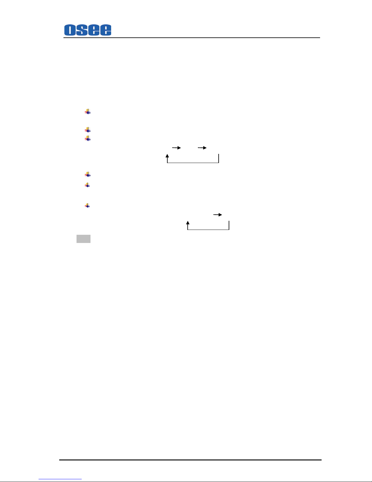
5/6: Two functions
Press “MENU” button to choose the function you need.
When the “MENU” is not in use, the button of 5/6 can achieve the following functions:
5. Blue only and mono button:
Blue only: press to eliminate the red and green signals. Only blue signal is displayed as an
apparent monochrome picture on the screen.
Mono: press to display a monochrome picture.
Press the button repeatedly, the button function will circle as follows:
Blue only mono color mode
6. Audio Selection and MUTE button
Audio Selection: press to select the monitoring audio of the corresponding monitor.
Mute: press to mute the sound. “MUTE” will show a continuous flickering lasting for 10S.
To cancel the mute function, press the button again.
Press the button repeatedly, the button function will circle as follows:
Audio Selection Mute
Note: All monitors share one headphone jack. The indicator in lighting shows its audio is being
monitored; in flickering shows its audio is being muted of corresponding monitor.
7: Enter
Enter the menu items when menu is displayed;
Enter instant parameters adjustment when menu isn’t displayed. The following parameters can be
regulated: VOLUME, BRIGHTNESS, CONTRAST, SATURATION, SHARPNESS, HUE.
(For more information, please refer to “Chapter 4.3.1”)
8: HEADPHONE Jack:3.5mm Stereo HEADPHONE Jack
Page 11

RMD4342 LCD MONITOR User Manual
—7—
4.3.1 ENTER BUTTON
4.3 Quick Button Descriptions
When MENU is not used, you can press ENTER to regulate the following parameters: VOLUME,
BRIGHTNESS, CONTRAST, SATURATION, SHARPNESS, and HUE.
Press ENTER six times, parameters will cycle. You can get the exact value combined w ith buttons
of ∧(up)or ∨(down).
VOLUME: Used to regulate the volume. Range: -30~0dB, the maximum: 0dB.
BRIGHTNESS: Used to regulate the brightness, range: -116~139, the typical: 0.
CONTRAST: Used to regulate the contrast of image, range: -128~127, the typical: 0.
SATURATION: Used to regulate the saturation of image, range: -128~127, the typical: 0.
SHARPNESS: Used to regulate the sharpness of image, range: 0~15, the typical: 0.
HUE: Used to regulate the hue of image, range: -32~31, the typical: 0.
Note: To regulate the option DEFAULT, use the reset item in video 1/2 of the main MENU. You can reset
the following parameters of BRIGHTNESS, CONTRAST, SATURATION, SHARPNESS, and HUE.
4.3.2 USER BUTTON
Press the USER button on the front panel; it will display the following table. The table will
disappear after 3 seconds without operation.
USER FUNCTION
USER 1 H/V DELAY
OFF
USER can be used as quick-button, and include many options. When you choose one option, for
example, if you have already set USER at H/V DELAY, you can press “USER” directly to realize
each function of H/V DELAY, and need not set in the main MENU. Of course you can set “USER”
at other option accordingly.
The function of USER can be set in the main MENU. Set steps: press MENU, combined with
buttons of ∧(up)or ∨(down), you can find “USER CONFIG” in the sub-MENU, also combined
with buttons of ∧(up)or ∨(down), and you will find USER.
Page 12
RMD4342 LCD MONITOR User Manual
—8—
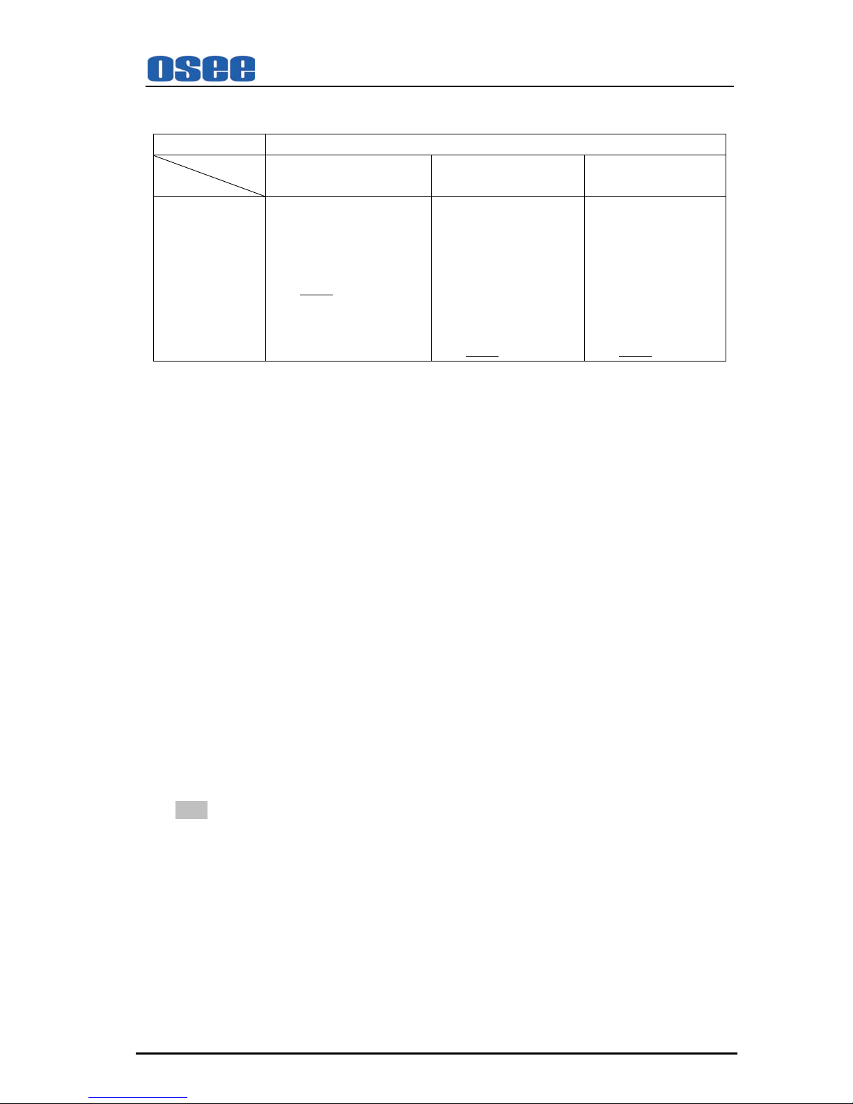
The different apparatus model includes different user menu items.
The options are as follows. (The underlined value means the DEFAULT value.)
Display (Viewing Area) :4.3”
MODEL
BUTTON ITEM
RMD4342-V RMD4342-SC RMD4342-HSC
USER SD ASPECT*
SAFE MARKER
AREA MARKER
OSD CONTROL
SCAN
H/V DELAY
SD ASPECT*
WFM DISP
SAFE MARKER
AREA MARKER
OSD CONTROL
MON SOURCE
H/V DELAY
SCAN
SD ASPECT*
WFM DISP
SAFE MARKER
AREA MARKER
OSD CONTROL
MON SOURCE
SCAN
And each option will be specified as follows.
H/V DELAY:H/V, V, H, OFF. Function: horizontal/vertical blank, vertical blank, horizontal
blank, or no blank.
SD ASPECT: Change the aspect ratio of the picture between 4:3 and 16:9. Only used for CVBS
and SD-SDI input signal. (For more information, please refer to Chapter 5.6)
WFM DISP: It is used to check the waveform / VECTOR of the current signal picture, showing
on the top-right of the screen. Include three options of WFM, VECTOR, OFF.
SAFE MARKER: Display CENTER mark, 90% mark and 80% mark or not.
AREA MARKER: Images show with one scale of 2.35:1, 1.85:1, 15:9, 14:9, 13:9, 4:3 or OFF.
Only when ASPECT is at 16:9, the setting is available.
OSD CONTROL: Display waveform / VECTOR / TC code, UMD code and audio meter or not.
MON SOURCE: Monitor one audio source of four audio sources. Include four options of MET1,
MET2, MET3 and MET4. When MET1 is selected, the first audio source will be monitored.
Likewise, if you select other MET, the corresponding audio source will be monitored.
SCAN: Press to display the 100% image (UNDER SCAN) and 95% (NORMAL) image.
Note: Please set “USER1” to meet your actual requirement. For example, if you often use H/V
DELAY, you’d better set “USER1” at H/V DELAY.
4.3.3 MENU BUTTON
When you want to change the value of a parameter, you may use MENU, and you can follow four
steps.
Step 1:
Press MENU, and you can enter the main MENU.
Page 13
RMD4342 LCD MONITOR User Manual
—9—
Step 2:
Press buttons of ∧(up)or ∨(down) to choose an option, and the selected sub-MENU icon will
display in yellow. When you get one and press ENTER, and you can enter the sub-MENU.
Step 3:
Press buttons of ∧(up)or ∨(down) to choose a parameter, and the selected parameter will display
in yellow. Press ENTER, and press ∧ or ∨ to acquire the exact value. Press ENTER to set some
value.
Step 4:
Press MENU to return. You can follow the same step to set other parameters.
In a word, when you set a parameter, the buttons of ENTER,MENU,∧ and ∨ will be used
frequently. The function of each button is listed below.
ENTER: Enter the sub-menu and set the value of a parameter.
MENU: Return to the super-menu with no saving.
∧(up)or ∨(down): Switch the options in the same menu.
Note: i n all sub-menu of main menu, pressing “Menu” is to cancel the current set value and
return back to the menu of top level. If setting a value of some parameter, it’s required to
press “Enter” to save current set value.
Connectors
HD-SDI/SD-SDI inputs comply with SMPTE259M,SMPTE292M / ITU-R BT601.
Composite Video inputs comply with SMPTE-170M.
Tally lamps are active, when connected to ground.
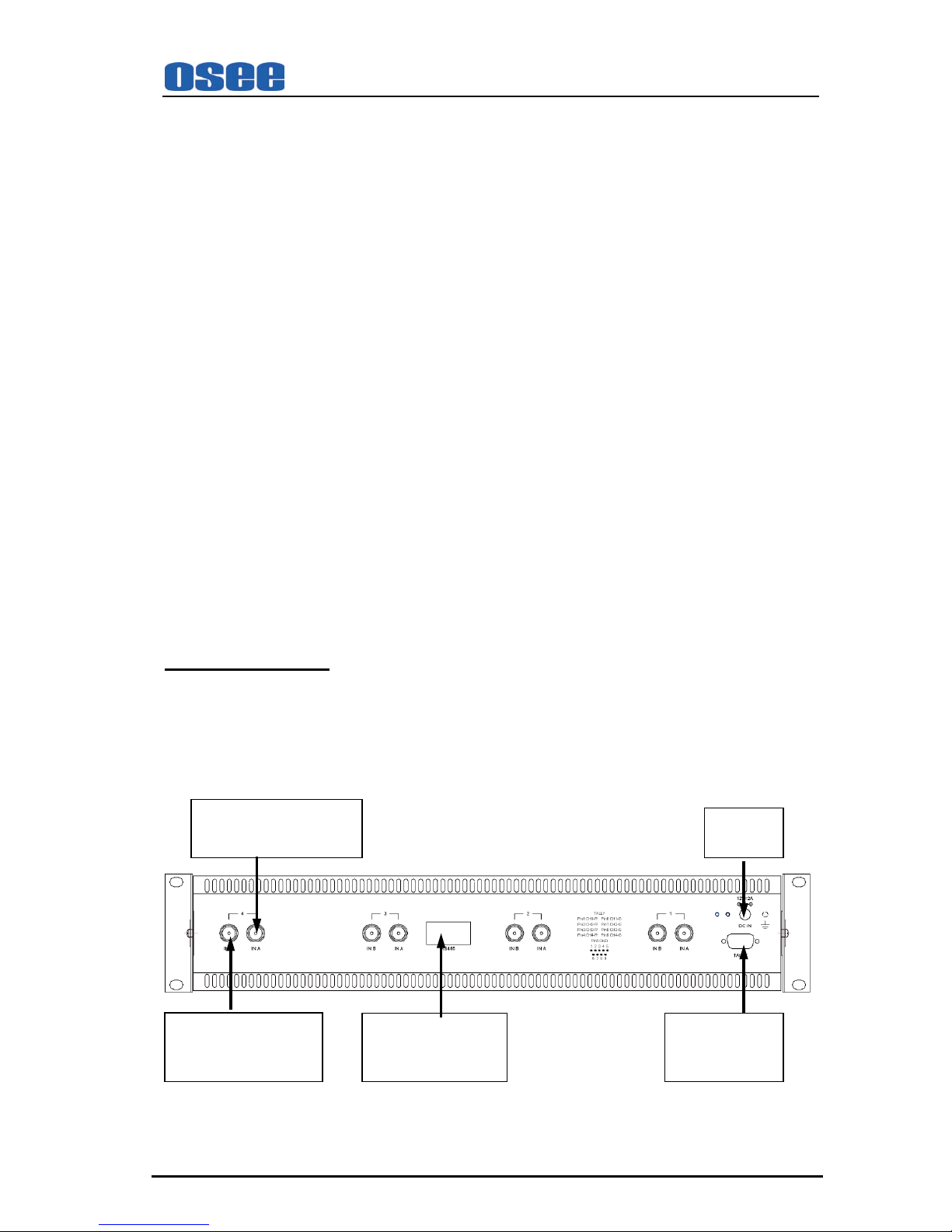
4.4 Rear Panel
Monitor 4 IN A
HD-SDI/SDI/ CVBS
12V DC
Monitor 4 IN B
HD-SDI/SDI/ CVBS
IN/ OUT RS485
TALLY IN
DB-9 Male
Page 14
RMD4342 LCD MONITOR User Manual
—10—
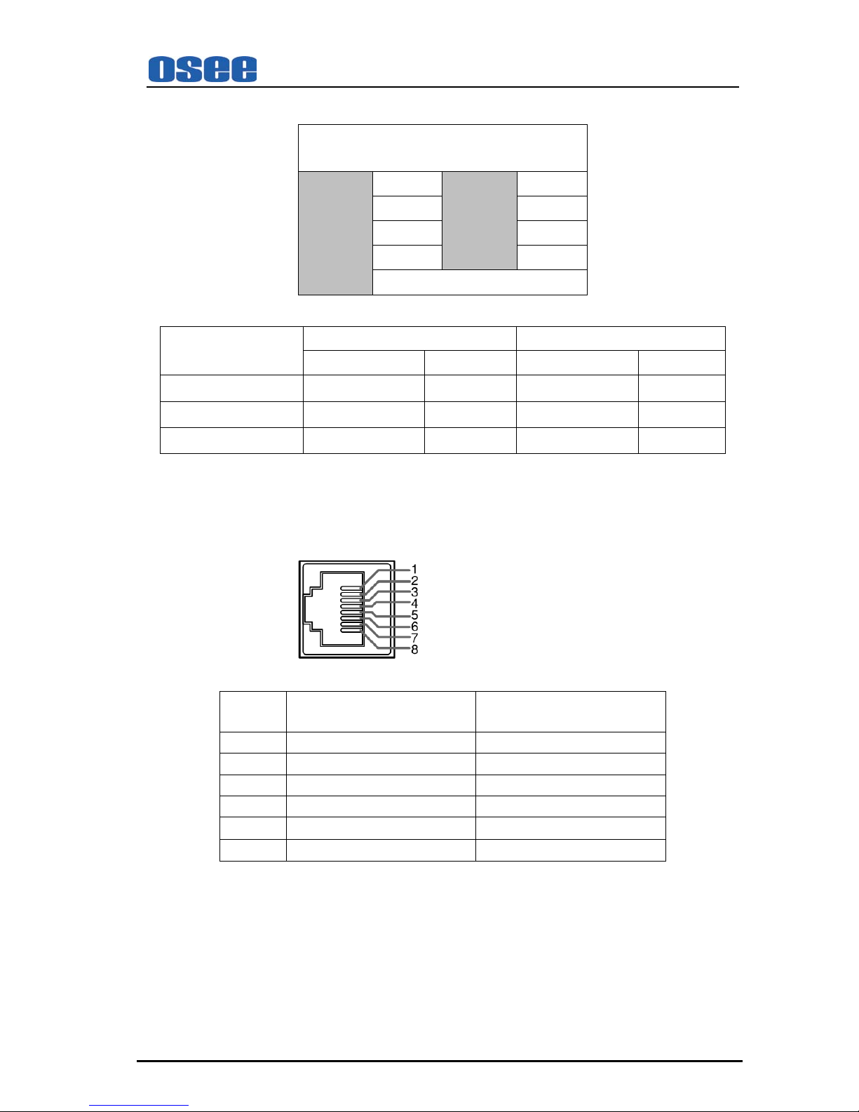
For Tally IN connector (DB9 male) :
Tally IN (DB-9 Male)
Pin 1 CH1-R Pin 6 CH1-G
Pin 2 CH2-R Pin 7 CH2-G
Pin 3 CH3-R Pin 8 CH3-G
Pin 4 CH4-R Pin 9 CH4-G
Pin 5 GND
T ally L ig ht C olor
Screen 1 Screen 2
PIN1 PIN6 PIN2 PIN7
Red
GND Open GND Open
Green
Open GND Open GND
Amber
GND GND GND GND
The descriptions of Screen 3 and Screen4 are similar with Screen 1.
For IN/ OUT RS485 connector (Female RJ-45):
Support for dynamic UMD and updating the new firmware.
( Female RJ-45 Receptacles )
Pin No. RS485 IN Terminal Signal RS485 OUT Terminal Signal
1,2 GND GND
3 Tx- Tx4 Rx+ Rx+
5 Rx- Rx6 Tx+ Tx+
7,8 NC NC
Page 15

RMD4342 LCD MONITOR User Manual
—11—
Chapter 5 Main Menu Structure
The descriptions of main menu structure are as follows:
(The operation of main menu refers to Chapter 4.3.3)
The main menu includes seven sub-menu icons. The sub-menus are:
A. STATUS
B. VIDEO
C. AUDIO
D. MARKER
E. OSD
F. USER CONTROL
G. USER CONFIG
Note: For the following menu description, “O” stands for the unit including this function; whereas “X”
indicates the unit includes no such function. The underlined values are factory preset setting values.
(The presets are values adjusted before shipment from factories.) The available parameters and
values show in white; the unavailable parameters and values show in blue.
5.1 STATUS Sub-menu
The STATUS Sub-menu is used to display the current status of the unit. The following items are
displayed:
Parameters
Input Signal
CVBS SD-SDI HD-SDI Display Val ue
FORMAT O O O
IN A
1080I60
COLOR TEMP O O O D65
MON SOURCE
O O O
MET 1
SCAN O O O NORMAL
SD ASPECT O O O 4:3
MODEL O O O RMD4342-HSC
This Sub-menu can’t be entered, only displays information. The model will display corresponding unit
type depending on the actual unit.
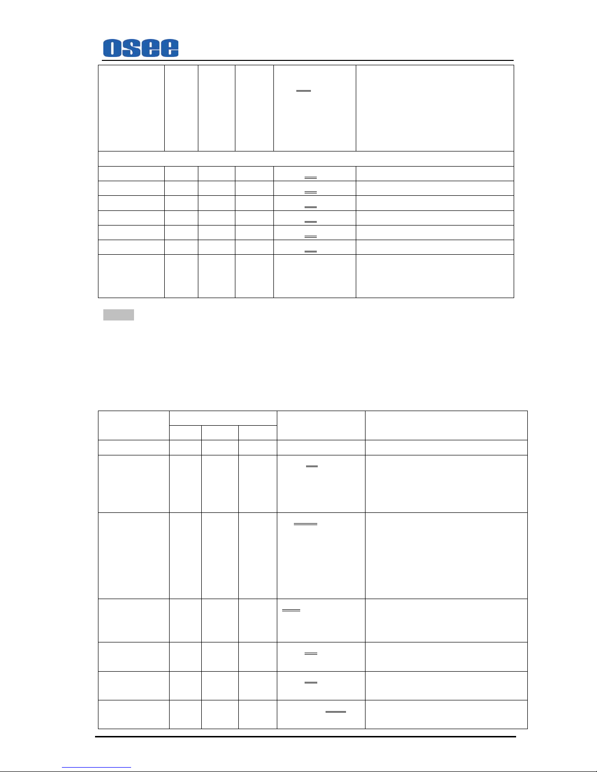
5.2 VIDEO Sub-menu
Parameters
Input Signal
Domain Range NOTE
CVBS SD-SDI HD-SDI
VIDEO (1/2)
BRIGHTNESS O O O -116…000 Adjust the picture brightness …139
CONTRAST O O O -128…000 Adjust the picture contrast …127
SATURATION O O O -128…000 Adjust the picture saturation …127
SHARPNESS O O O 000 Adjust the picture sharpness …15
HUE O O O -32…000 Adjust the picture hue …31
RESET O O O Reset BRIGHTNESS, CONTRAST,
SATURATION, SHARPNESS,
HUE to
default value. Once “Reset” is set, all
parameters above will respond to change.
Page 16
RMD4342 LCD MONITOR User Manual
—12—
COLOR TEMP
O O O USR…D56…
D65
…D93
Used to select the color temperature that
will become the basis for adjustments.
<USR> Color temperature of user set.
<D56> Color temperature around 5600K
<D65> Color temperature around 6500K
<D93>Color temperature around 9300K
VIDEO (2/2)
R GAIN
O O O 0…128…255 Gain elements for RED are adjusted.
G GAIN
O O O 0…128…255 Gain elements for GREEN are adjusted.
B GAIN
O O O 0…128…255 Gain elements for BLUE are adjusted.
R OFFSET
O O O 0…128…255 Offset elements for RED are adjusted.
G OFFSET
O O O 0…128…255 Offset elements for GREEN are adjusted.
B OFFSET
O O O 0…128…255 Offset elements for BLUE are adjusted.
RESET
O O O “R GAIN”- “B OFFSET” values are reset
to color temperatures values selected in
“COLOR TEMP”.
NOTE: When adjusting, the item displays of “BRIGHTNESS”-“HUE” and “R GAIN”-“B OFFSET” move to
the lower part of the screen.
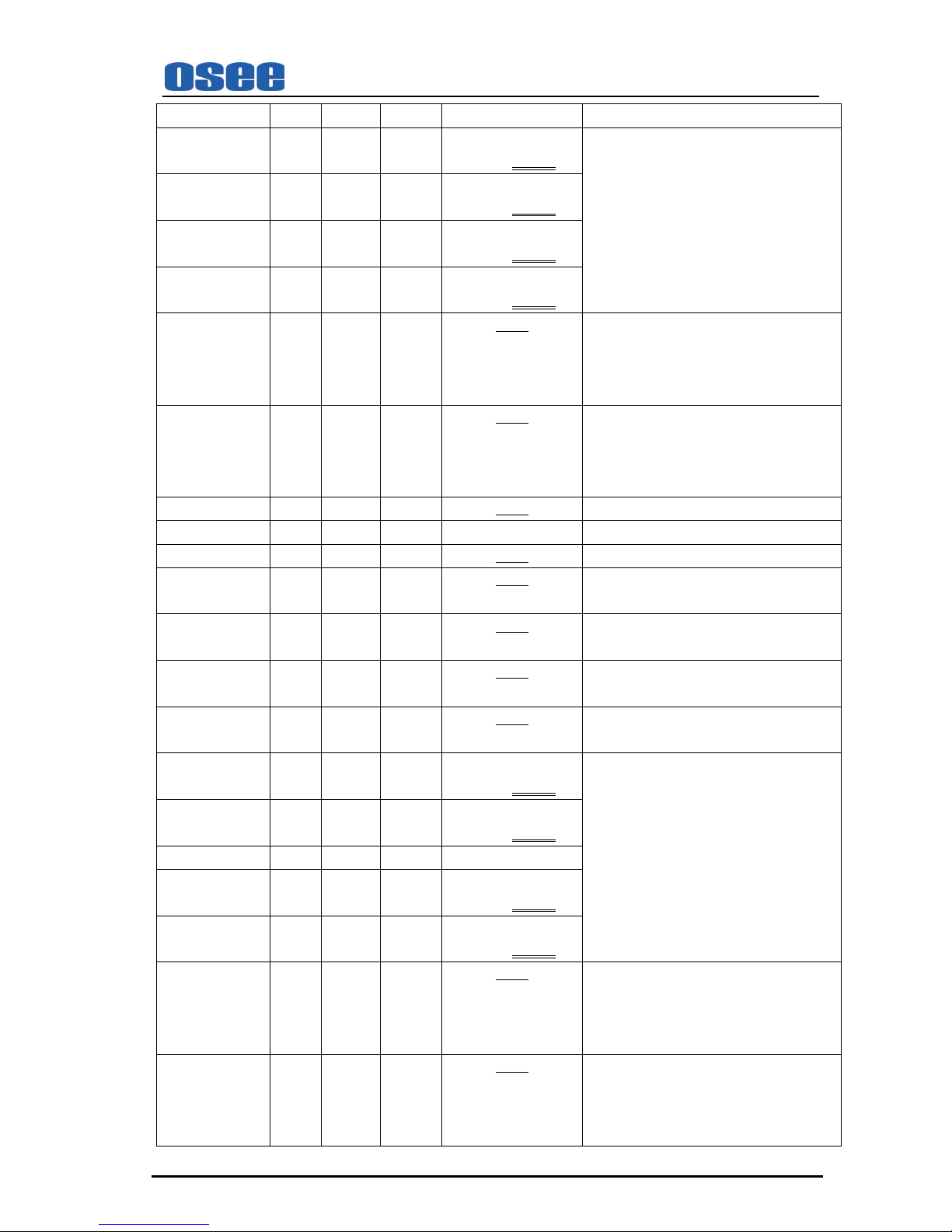
5.3 AUDIO Sub-menu
The AUDIO sub-menu only applies to RMD4342-HSC and RMD4342-SC.
PARAMETERS
Input Signal
Domain Range NOTE
CVBS SD-SDI HD-SDI
AUDIO (1/5)
AUDIO MON
O O O ON…OFF Used for headphone. The default of left panel
is set to ON, others is set to OFF. “AUDIO
MON” can be only set from “OFF” to “ON”,
a reverse cannot be allowed.
MON SOURCE
O O O MET 1…MET 4 Used to set the monitoring audio source
from among audio meters.
For RMD4342-HSC, there are four
audio meters (MET1~MET4).
For RMD4342-SC, there are only two
audio meters (MET1~MET2).
VOLUME O O O 00dB…-30dB…MUTE Used to adjust the volume value.
“MUTE” changes to a continuous flickering
lasting for 10S.
METER H POS L O O O 000…255 Used to set the horizontal position of left
audio meter.
METER H POS R O O O 000…255 Used to set the horizontal position of right
audio meter. Only used for RMD4342-HSC.
TEST LEV O O O -18dB…-20dB Used to set the test level of audio meter.
Page 17
RMD4342 LCD MONITOR User Manual
—13—
AUDIO (2/5)
IN A: MET 1 O O O NONE…VU
…PK…VU+PK
Used to set the audio meter types with the
input signal from INA connector.
Note:
For RMD4342-HSC, there are four audio
meters (MET1~MET4).
For RMD4342-SC
, there are only two
audio meters (MET1~MET2).
IN A: MET 2 O O O NONE…VU
…PK…VU+PK
IN A: MET 3 O O O NONE…VU
…PK…VU+PK
IN A: MET 4 O O O NONE…VU
…PK…VU+PK
IN A: MET 1 -L O O O For the input signal from INA connector, it is
used to assign the audio channel for left audio
meter 1 display
from among
“EBD1…EBD16”.
EBD1
IN A: MET 1-R O O O For the input signal from INA connector, it is
used to assign the audio channel for right
audio meter 1 display
from among
“EBD1…EBD16”.
EBD2
IN A: MET 2-L O O O The similar as INA meter 1. EBD3
AUDIO (3/5)
IN A: MET 2-R O O O The similar as INA meter 1. EBD4
IN A: MET 3-L O O O The similar as INA meter 1. Only used for
RMD4342-HSC.
EBD5
IN A: MET 3-R O O O The similar as INA meter 1. Only used for
RMD4342-HSC.
EBD6
IN A: MET 4-L O O O The similar as INA meter 1. Only used for
RMD4342-HSC.
EBD7
IN A: MET 4-R O O O The similar as INA meter 1. Only used for
RMD4342-HSC.
EBD8
IN B: MET 1 O O O NONE…VU
…PK…VU+PK
For the input signal from INB connector, it is
used to set the audio meter types with the
input signal from INB connector.
Note:
For RMD4342-HSC, there are four audio
meters (MET1~MET4).
For RMD4342-SC, there are onl
y two
audio meters (MET1~MET2).
IN B: MET 2 O O O NONE…VU
…PK…VU+PK
AUDIO (4/5)
IN B: MET 3 O O O NONE…VU
…PK…VU+PK
IN B: MET 4 O O O NONE…VU
…PK…VU+PK
IN B: MET 1-L O O O For the input signal from INB connector, it is
used to assign the audio channel for left audio
meter 1 display
from among
“EBD1…EBD16”.
EBD1
IN B: MET 1-R O O O For the input signal from INB connector, it is
used to assign the audio channel for right
audio meter 1 display
from among
“EBD1…EBD16”.
EBD2
Page 18

RMD4342 LCD MONITOR User Manual
—14—
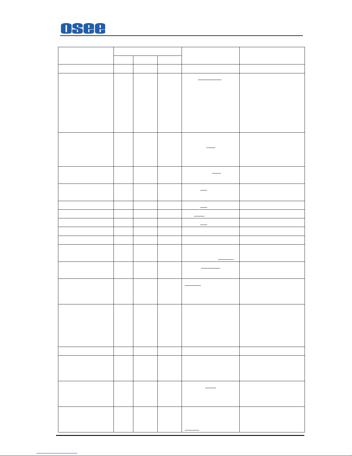
IN B: MET 2-L O O O The similar as INB meter 1. EBD3
IN B: MET 2-R O O O The similar as INB meter 1. EBD4
IN B: MET 3-L O O O The similar as INB meter 1. Only used for
RMD4342-HSC.
EBD5
AUDIO (5/5)
IN B: MET 3-R O O O The similar as INB meter 1. Only used for
RMD4342-HSC.
EBD6
IN B: MET 4-L O O O The similar as INB meter 1. Only used for
RMD4342-HSC.
EBD7
IN B: MET 4-R O O O The similar as INB meter 1. Only used for
RMD4342-HSC.
EBD8
5.4 MARKER Sub-menu
PARAMETERS
Input Signal
Domain Range NOTE
CVBS SD-SDI HD-SDI
SAFE MARKER O
1
O O ON…OFF Select ON to enable
the safe
area mark of the picture display
and OFF not to display.
CENTER O O O ON…OFF Select ON to display the center
mark of the picture and OFF not
to display.
No function in h/v delay mode
90% O O O ON…OFF Select ON to enable
the 90%
safe area size of the image
display and OFF not to display.
No function in h/v delay mode
80% O O O ON…OFF Select ON to enable
the 80%
safe area size of the image
display and OFF not to display.
No function in h/v delay mode
AREA MARKER
X
2
O O OFF…2.35:1
…1.85:1…15:9
…14:9…13:9
…4:3
Used to set type of
the area
marker.
No function in h/v delay mode
and in 4:3 aspect ratio for SD
SDI input
Note:
1. SAFE MARKER
When SAFE MARKER is set to ON, the value of “CENTER”,“90%”,“80%”changes
between ON, OFF. Each function is available.
When SAFE MARKER is set to OFF, the functions of “CENTER”,“90%”,“80%” are not
available.
2. Refer to the “AREA
MARKER” parameter:
Only when the image displaying in 16:9 format, this function is available.
Page 19
RMD4342 LCD MONITOR User Manual
—15—
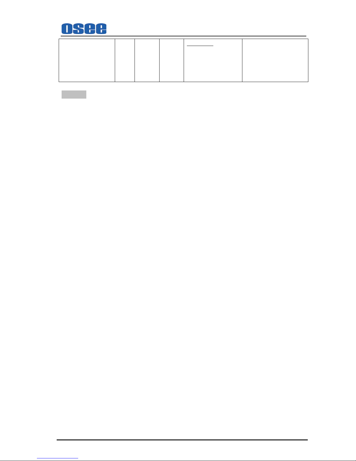
5.5 OSD Sub-menu
PARAMETERS
Input Signal
Domain Range NOTE
CVBS SD-SDI HD-SDI
OSD (1/3)
STD DISP O O O ON…AUTO OFF Displays
the input signal
format on the top left of the
screen.
• ON = Always displayed
• AUTO OFF= Displayed for
about 10 seconds after change
• OFF = Hidden
…OFF
WFM/VT DISP
X O O VECTOR…WFM… •VECTOR: Displays
vectorscope.
•WFM: Displays waveform
• OFF: not to display
OFF
TC DISP X O O ON… • ON: Displays the time code
• OFF: not to display
OFF
UMD DISP O O O ON • ON: Displays UMD
•OFF: not to display
…OFF
OSD TLY DISP *
O
1
O O ON …OFF
OSD TLY MODE *
O
1
O O RGY …GR…GR
LED TLY DISP
O
*2
O O ON …OFF
OSD (2/3)
UMD FIXED SETUP
O
*3
O O
@ABCDEFGHIJKLMNO
16 CHARS
COLOR
O
*4
O O RED…GREEN
…YELLOW…
WHITE
ALIGN
O
*5
O O LEFT…CENTER …
RIGHT
UMD PROTOCOL
O
*6
O O LOCAL …TSL V3.1
…TSL V4.0…IMAGE
VIDEO
UMD ID
O
*7
O O 0…255
The device can be set
independently through the
downloading software and
with the set value, convenient
for remote control
OSD (3/3)
UMD NAME(S/N)
O
*8
O O S00000 16 Characters totally. UMD
NAME is in compliance with
IMAGE VIDEO Protocol
UMD TL Y MODE
O
*9
O O T1…T2…T1T2 UMD TLY MODE is in
compliance with IMAGE
VIDEO Protocol
…T2T1
…T1-…T2-…T1T2…T2T1-…
UMD BAUD RATE
O
*10
O O 2400…4800…9600…
19200…38400…57600…
115200
Page 20
RMD4342 LCD MONITOR User Manual
—16—
TLY SOURCE
O
*11
O O STANDARD …IMAGE
VIDEO HW…IMAGE
VIDEO 422…
STANDARD+IV422…
TSL
NOTES:
*1. OSD TLY DISP, OSD TLY MODE
Use these settings to choose how tally is displayed on the screen. The avai l able OSD Tally
options depend on the Tally Source. OSD TLY DISP can be set to Off
,ON;OSD TLY MODE
can be set to RGY, RG, or GR:
When the Tally Source is set to STANDARD or STANDARD+IV422, OSD TLY MODE is available.
When the Tally Source is set to IMAGE VIDEO 422、TSL and IMAGE VIDEO HW, OSD TLY MODE is
unavailable.
• Off: On-screen tally is disabled.
• ON: On-screen tally is enabled.
• RGY: Red, yellow, or green tally signals are indicated at both the bottom left and bottom right
corners of the screen near UMD.
• RG: Red tally is shown at the bottom left of the screen and green is sho wn at the bot tom right.
• GR: Green tally is shown at the bottom lef t of the screen and red is shown at the bottom right.
*2. LED TLY DISP
Use this setting to enable or disable the LED Tally. When it is set to ON, the yellow, red and
green LED above each display will respond to tally commands, according to the Tally Source
setting.
*3. UMD FIXED SETUP
Use this setting to display static UMD text on the screen. This setting is used to enter UMD text
locally, when a serial protocol i s not used for remote c ontrol. The UMD will be ov erridden by serial
protocol commands.
Press ENTER to edit the UMD. Use the ENTER button to move t he cursor. Pr ess ENTER with the
cursor on the character to be changed and use the Up/Down button to scroll through character
options. Press ENTER to choose a ch aracter. Press MENU to return to the up menu and save the
UMD setting.
*4. COLOR
Use this setting to choose the color of the UMD text. Available colors are red, green, yellow and
white. This setting does not affect text color when using UMD text via the Image Video or TSL
protocols (text color is set via the protocols).
*5. ALIGN
Use this setting to choose the horizontal alignment of the UMD text. UMD text can be justified on
the left, center or right of the screen. This setting i s overridden when using UMD text via the
Image Video protocol (alignment is set via Im age Vi deo prot ocol).
Page 21
RMD4342 LCD MONITOR User Manual
—17—
*6. UMD Protocol
Use the UMD Protocol menu option to choose the protocol with which the unit receives remote
commands. Currently, four protocols are avai l able.
Image Video
Use the Image Video protocol setting when cont roll ing the UMD from an Image Video tally
controller (e.g. TSI-1000) or other controlling device which utilizes the Image Video prot ocol.
The UMD ID, UMD Name(S/N), and Baud Rate parameters m ust be set for each screen in
conjunction with the controlling device.
TSL v4.0
Use the TSL v4.0 protocol setting when controlling the UMD from a TSL tally controller, or
other controlling device which utilizes the TSL v4.0 protocol. The UMD ID must be set f or
each screen in conjunction with the controlling device.
TSL v3.1
Use the TSL v3.1 protocol setting when controlling the UMD f rom a TSL tally controller, or
other controlling device which utilizes the TSL v3.1 protocol. The UMD ID must be set for
each screen in conjunction with the controlling device.
LOCAL
The static UMD is set by the local unit. The others of UMD Protocol can be set by Local
and the corresponding protocols.
*7. UMD ID
The UMD ID identifies each screen to the contr olling dev ice. When using the TSL protocol, t he ID
of each screen should be manually set in conjunction with the controlling device. When using the
Image Video protocol, the ID may be set automatically by the controlling device, after each UMD
is initially identified by UMD Name (see “UMD Name[ S/N]” below). Available IDs are 000-255.
*8. UMD Name (S/N)
Use this setting to assign a name to each screen when using the Image Video p rotocol. The UMD
name is equivalent to the Image Video serial number and is used by the Image Video
controlling device to identify each screen. The default UMD Nam e(S /N) is “S00000.” It is
recommended to maintain this naming scheme in order to avoid serial number conflicts with other
Image Video devices on the same serial bus. Each name can b e up to 16 ASCII characters.
Press ENTER to edit the UMD. Use the ENTER button to move t he cursor. Pr ess ENTER with the
cursor on the character to be changed and use the Up/Down button to scroll through chara cter
options. Press ENTER to choose a ch aracter. Press MENU to return to the up menu and save the
UMD setting.
*9. UMD TLY Mode
Use this setting when using Image Video tally cont rol. Choose one of the following settings, in
conjunction with the Image Video controlling devic e. T1, T2, T1T2, T2T1, T1-, T2-, T1T2-, T2T1-.
Consult Image Video documentation for further inf ormation.
*10. UMD Baud Rate
Use this setting to choose the baud rate. The baud r ate must be set in conjunction with the
controlling device. Available baud rates are 2400, 4800, 9600, 19200, 38400, 57600, 115200.
Page 22
RMD4342 LCD MONITOR User Manual
—18—
*11. Tally Source
The unit tally (OSD and LED) can be controlled in a variety of different ways. Use the Tally
Source setting to choose how tally is controlled:
Standard
Use the Standard setting to control tally via contact closure on the DB-9 tally interface.
Image Video HW
Use the Image Video HW setting to control Image V i deo tally states via contact closure
on the DB-9 tally interface. Contact closure of the Red pin corresponds to Image Video
Tally 1, and the Green pin maps to Image Video Tally 2. Contact closure (ground)
corresponds to a LOW state, and open circuit corre sponds to a HIGH state. This mode
requires the UMD Tally Mode parameter to be set . Consult Image Video documentation
for further information.
Image Video 422
Use the Image Video 422 setting to control Image Video tally states via the Image Video
serial protocol. This mode requires the UMD Tal ly Mode parameter to be set. Consult
Image Video documentation for further information.
Standard + IV422
Use the Image Video 422 setting to control Image Video tally states via the Image Video
serial protocol, while controlling LED and OSD tally using contact closure on the DB-9
tally interface. This mode requires the UMD Tally Mode par am eter to be set. Consult
Image Video documentation for further information.
TSL
Use the TSL setting to control OSD and LED tally via the TSL protocol.
5.6 USER CONTROL Sub-menu
PARAMETERS
Input Signal
Domain Range NOTE
CVBS SD-SDI HD-SDI
SCAN
O O O NORMAL Used to adjust the image
display scale.
…UNDER SCAN
NORMAL: 95%
UNDER SCAN:100%
SD ASPECT
O
1
O X 4:3… Used to adjust the screen
Aspect Ratio.
16:9
H/V DELAY X O O OFF Used to observe the horizontal
and vertical sync signal s at the
same time.
…H…V…H/V
COLOR BAR
O
2
O O ENABLE…
DISABLE
1. For “SD ASPECT” parameter:
SD ASPECT: The screen Aspect Ratio. The screen Aspect Ratio value: 4:3 and 16:9.
SD ASPECT function
Type/ input signal
16:9 4:3
RMD4342-HSC
(16:9 screen)
HD-SDI input signal -
-
SD-SDI input signal
CVBS input signal
Page 23
RMD4342 LCD MONITOR User Manual
—19—
SD ASPECT function
Type/ input signal
16:9 4:3
RMD4342-SC
(16:9 screen)
SD-SDI input signal
CVBS input signal
RMD4342-V
(16:9 screen)
CVBS input signal
“”:Available ; “- ” Not available.
When the HD-SDI signal input, it will display in 16:9 by default.
2. For “Color bar” parameter:
When opening the color bar, the screen information will be covered by the color bar for one minute.
The color bar also can be canceled by pressing the ∧button,∨ button ,“ENTER” button or
“MENU” button.
5.7 USER CONFIG Sub-menu
PARAMETERS
Input Signal
Domain Range NOTE
CVBS SD-SDI HD-SDI
VECTOR REF
O O O 100% CB
…
Used to set the reference value of the
vectorscope.
75% CB
100% CB: 100% color bar
75% CB: 75% color bar
OSD CONTROL O O O ON
Except STATUS, it controls the switch
of all OSD
…OFF
WFM/ VT MODE
O O O SOLID Used to set the transparence
of the
waveform and vectorscope.
…75%
…50%…25%
SOLID:100%over cover the
background
75%:75%over cover the background
50%:50%over cover the background
25%:25%over cover the background
USER O O O
See
Chapter 4.3.2
SCAN
Page 24

RMD4342 LCD MONITOR User Manual
—20—
Chapter 6 Technical Specifications
Product detailed information
Number of Screens
:
4
Screen Display Ratio
16:9
Display (Viewing Area)
4.3” diagonal (95.04mm x 53.856mm)
Viewing Angles
160°H x160° V
Screen Colors (Bit Depth)
16.7M
Resolution (Dots)
480H × 272V
Pixel Pitch (mm)
0.198(H) × 0.198(V)
Contrast Ratio
400 :1
Pixel Response
<30ms typical
Luminance, White (cd /㎡) 165
Back light
White LED
Dimensions
19”W x 3.5”H x 2.4”D (481.6mm x 88mm x 61mm)
Power Consumption
12V DC/10 watts. – (3.8 Amps max –CE & UL complied supply included)
Operating Temperature
0° C to 60° C
Inputs
Eight HD-SDI / SD-SDI/ Analog Composite connectors(BNC)
One RS485 input connector (RJ45)
Outputs
One RS485 output connector (RJ45)
Product Number
Signal Format
RMD4342 are compatible with the following Signal Formats:
Signal Formats
RMD4342-HSC
NTSC、PAL
480i-59.94、576i-50
1035i-59.94、1035i-60、1080i-50、1080i-59.94、1080i-60、1080p-23.97、
1080p-24、1080p-25、1080p-29.97、1080p-30、1080PsF-23.97、1080PsF-24、
720p-50、720p-59.94、720p-60、720p-23.97、720p-24、720p-25、720p-29.97、
720p-30
RMD4342-SC
NTSC、 PAL
480i-59.94、576i-50
RMD4342-V NTSC、 PAL
Page 25
RMD4342 LCD MONITOR User Manual
—21—
The relationships between the actual display form (on the top left of the screen)and input
signal format are as follows:
Signal Format Support Form Display Form
1080/60I
1080/60I 1080I60
1080/59.94I 1080I59.94
1080/50I
1080/50I 1080I50
1080/30P
1080/30P
1080P30
1080/29.97P
1080P29.97
1080/25P
1080/25P
1080P25
108024P
1080/24P
1080P24
1080/23.97 1080P23.97
1080/24PsF
1080/24PsF 1080sF24
1080/23.97PsF 1080Sf23.97
1035/60I
1035/60I 1035I60
1035/59.94I 1035I59.94
720/60P
720/60P 720P60
720/59.94P
720P59.94
720/50P
720/50P
720P50
720/30P
720/30P
720P30
720/29.97P
720P29.97
720/25P
720/25P 720P25
720/24P
720/24P 720P24
720/23.97P 720P23.97
576/50I
576/50I 576I50
480/60I
480/59.94I 480I60
NTSC
NTSC
NTSC
PAL
PAL
PAL
Page 26

RMD4342 LCD MONITOR User Manual
—22—
Dimensions:
Front View Unit: mm
Rear View and Side View Unit: mm
Top Side View Unit: mm
Page 27
RMD4342 LCD MONITOR User Manual
—23—
Chapter 7 Warranty for LCD Monitor
What the warranty covers:
osee warrants its products to be free from defects in material and workmanship during the warranty
period of one year from purchase date. If a product proves to be defective in material or workmanship
during the warranty period, osee will, at its sole option, repair or replace the product with a similar
product. The replacement unit will be covered by the balance of the time remaining on the customer’s
original limited warranty.
No sales personnel of the seller or any other person is authorized to make any warranties other than those
described above, or to extend the duration of any warranties on behalf of osee, beyond the time period
describe above.
This warranty is extended to the first consumer only, and proof of purchase is necessary to honor the
warranty. If there is no proof of purchase provided with a warranty claim, osee reserves the right not to
honor the warranty set forth above. Therefore, labor and parts may be charged to the consumer.
What the warranty does not cover:
1. Any product, on which the serial number has been defaced, modified or removed.
2. Damage, deterioration or malfunction resulting from:
Accident, misuse, neglect, fire, water, lightning, or other acts of nature, unauthorized product
modification, or failure to follow instructions supplied with the product
Repair or attempted repair by anyone not authorized by osee
Any damage of the product due to shipment.
Removal or installation of the product.
Causes external to the product, such as electric power fluctuations or failure.
Use of supplies or parts not meeting osee product’s specifications.
Normal wear and tear.
Any other cause which does not relate to a product defect.
 Loading...