

Page 1

PRM1014 Monitor
User Manual
Page 2

Page 3

3
Product Information
MODEL: PRM1014 Monitor
VERSION: V010100
RELEASE DATE: June 21th, 2016
Company
OSEE TECHNOLOGY CO., LTD.
Contact Information
Address: No.22 Building, No.68 zone, Beiqing Road, Haidian District, Beijing,
China
Post Code: 100094
Tel: 010-62434168
Fax: 010-62434169
http://www.osee-dig.com/
E-mail: [email protected]
Page 4
About this manual
Important
The following symbols are used in this manual:
The further information or know-how for described subjects above which
helps user to understand them better.
The safety matters or operations that user must pay attention to when
using this product.
Contents
The user manual applies to the following device types:
PRM1014-3HSV
PRM1014-HSV
PRM1014-SV
The images of PRM1014-3HSV are adopted in the following descriptions.
Any of the different specifications between the device types are elaborated.
Before reading the manual, please confirm the device type.
Page 5

I
Contents
Contents .......................................................................................................... I
Chapter 1 Overview ....................................................................................... 1
Chapter 2 Safety ............................................................................................. 3
Chapter 3 Unpack and Installati on ............................................................... 7
Chapter 4 PRM1014 Features ........................................................................ 9
4.1
Front Panel Features ........................................................................ 11
4.1.1 Arrangement of Front Panel ........................................................... 11
4.1.2 Operation of Front Panel ................................................................ 12
4.2
Rear Panel Features .......................................................................... 17
4.2.1 Arrangement of Rear Panel ............................................................ 17
4.2.2 Operations of Rear Panel ............................................................... 18
4.3
Supported Signal Format ................................................................. 20
Chapter 5 Functionality of the Main Menu ................................................. 23
5.1
Main Menu ......................................................................................... 23
5.1.1 STATUS Menu ............................................................................... 25
5.1.2 INPUT SELECT Menu .................................................................... 27
5.1.3 MARKER Menu .............................................................................. 29
5.1.4 AUDIO Menu .................................................................................. 33
5.1.5 DISPLAY Menu .............................................................................. 36
5.1.6 CLOSED CAPTION Menu .............................................................. 39
5.1.7 CONFIG Menu ................................................................................ 40
5.1.8 COLOR TEMP Menu ...................................................................... 45
5.1.9 FUNCTION KEY Menu ................................................................... 47
5.1.10 IMD Menu ..................................................................................... 49
5.2
Menu Settings .................................................................................... 64
Chapter 6 Network Control .......................................................................... 69
6.1
Access the settings ........................................................................... 69
6.2
Menu Control ..................................................................................... 70
6.2.1 ADJUST Menu ................................................................................ 72
6.2.2 VIDEO DISPLAY Menu .................................................................. 73
6.2.3 SYSTEM Menu ............................................................................... 74
6.2.4 Other Menus ................................................................................... 75
6.3
Parameter Settings ........................................................................... 75
Page 6

II
Chapter 7 Specifications ............................................................................. 79
Page 7
Overview
1
Chapter 1 Overview
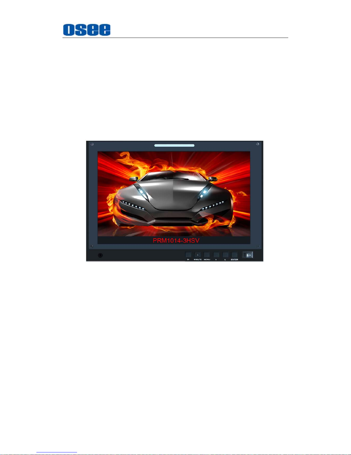
PRM1014 is a 10.1”, single screen, high full HD portable monitor. It has a
dedicate and simple outlook, and offers a full resolution 1920X1200 LCD panel,
with wide viewing angle and wide color gamut. It supports the video signal of
analog composite/3G/HD/SD-SDI and HDMI. It supports analog audio
input/output. It supports precise color correction, audio meter display, wave
form, vector and so on.
Figure 1 A Diagram of PRM1014
Features
Supports 3G/HD/SD-SDI, analog composite video signal and HDMI
1.3a
Offers LCD panel with resolution of 1920 X1200, high-brightness,
high-contrast and 178° wide viewing angle
Supports color gamut modes that meet the criteria of SMPTE-C, EBU,
ITU-709
Supports various color temperature and user customized color
temperature
Supports multiple power supply modes: AC adapter, external battery
Presets external battery plate, and supports various battery
plates(SONY F-970, Panasonic D54S, Canon LP-E6)
Page 8

Overview
2
Functionality
Audio phase meter and phase alarm display
16 channels embedded audio level meter, the channel number and the
dB value can be displayed
Supports various markers: Center Marker, Area Marker and Safety
Marker
Supports TSL/IMAGE VIDEO dynamic TALLY protocol
Supports TC code(VITC, LTC, D-VITC)
Supports AFD prompts display
Supports H/V Delay, NATIVE, BLUE ONLY, MONO
Speaker and earphone output
Supports Ethernet control
3G supports 1080P 50, 1080P 60
Page 9

Safety
3
Chapter 2 Safety
FCC Caution:
Any Changes or modifications not expressly approved by the party responsible
for compliance could void the user's authority to operate the equipment.
This device complies with part 15 of the FCC Rules.
Operation is subject to the following two conditions: (1) This device may not
cause harmful interference, and (2) this device must accept any interference
received, including interference that may cause undesired operation.
Note: This equipment has been tested and found to comply with the limits for a
Class B digital device, pursuant to part 15 of the FCC Rules. These limits are
designed to provide reasonable protection against harmful interference in a
residential installation. This equipment generates uses and can radiate radio
frequency energy and, if not installed and used in accordance with the
instructions, may cause harmful interference to radio communications.
However, there is no guarantee that interference will not occur in a particular
installation. If this equipment does cause harmful interference to radio or
television reception, which can be determined by turning the equipment off and
on, the user is encouraged to try to correct the interference by one or more of
the following measures:
Reorient or relocate the receiving antenna.
Increase the separation between the equipment and receiver.
Connect the equipment into an outlet on a circuit different from that to which
the receiver is connected.
Consult the dealer or an experienced radio/TV technician for help.
Page 10
Safety
4
Warnings:
Read, keep and follow all of these instructions for your safety. Heed all
warnings.
Monitor
Do not beat with a hard object or scratch the LCD display.
Do not make the freeze picture displaying on the screen time too long,
otherwise, it will leave the afterimage on the screen.
Install in accordance with the manufacturer's instructions.
If the brightness is adjusted to the minimum, then it might be hard to
see the display screen.
Refer all servicing to qualified service personnel. Servicing will be
required under all of the following conditions:
The unit has been exposed to rain or moisture.
Liquid had been spilled or objects have fallen onto the unit.
The unit has been damaged in any way, such as when the
power-supply cord or plug is damaged.
The unit does not operate normally.
Clean only with dry cloth.
Specifications are subject to change without notice.
Position
Do not block any ventilation openings.
Do not use this unit near water.
Do not expose the unit to rain or moisture.
Do not use this unit near any heat sources such as radiators, heat
Page 11

Safety
5
registers, stoves, or other apparatus (including amplifiers) that product
heat.
A nameplate indicating operating voltage, etc., is located on the rear
panel.
The socket-outlet shall be installed near the equipment and shall be
easily accessible.
Power Supply Cord
Do not defeat the safety purpose of the polarized or grounding-type
plug.
Do not damage the power cord, place the heavy objects on the power
cord, stretch the power cord, or bend the power cord.
Protect the power cord from being walked on or pinched, particularly at
plugs, convenience receptacles, and the point where they exit from the
unit.
If the power cord is damaged, turn off the power immediately. It is
dangerous to use the unit with a damaged power cord. It may cause
fire or electric shock.
Unplug this unit during lighting storms or when unused for long periods
of time.
Disconnect the power cord from the AC outlet by grasping the plug, not
by pulling the cord.
Should any solid object or liquid fall into the cabinet, unplug the unit
and have it checked by qualified personnel before operating it any
further.
Page 12

6
Page 13
Unpack and Installation
7
Chapter 3 Unpack and Installation
Unpack:
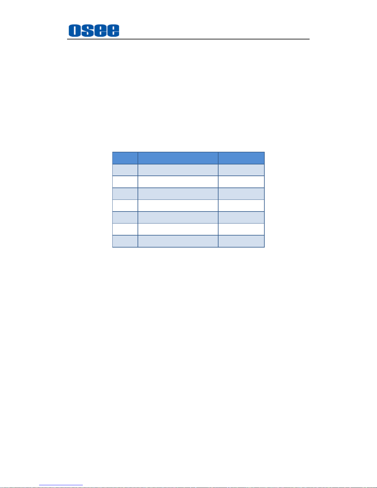
When unpacking the components of PRM1014 monitor, please verify that none
of the components listed in Table 3.1 are damaged or lack. If there is any
missing, contact your dealers or OSEE TECHNOLOGY CO., LTD. for it.
Table 3.1 Packing List
No. Item Quantity
1 Monitor 1
2 Power cord 1
3 Power adapter 1
4 Battery plate(optional) 1/2
5 User manual 1
6 warranty card 1
7 Certificate Card 1
Installation:
1.
Prepare for installation
Please follow the procedures below before installing PRM1014 monitor:
Check the equipment for any invisible damage that may have occurred
during transit.
Confirm all the items listed on the packing list have been received.
Remove all the packing material including electrostatic-resistant
packing.
Retain these packing for future use.
2.
Install PRM1014 in your desired location of an equipment rack.
Adequate ventilation is required when installed to prevent possible
damage to the PRM1014internal components.
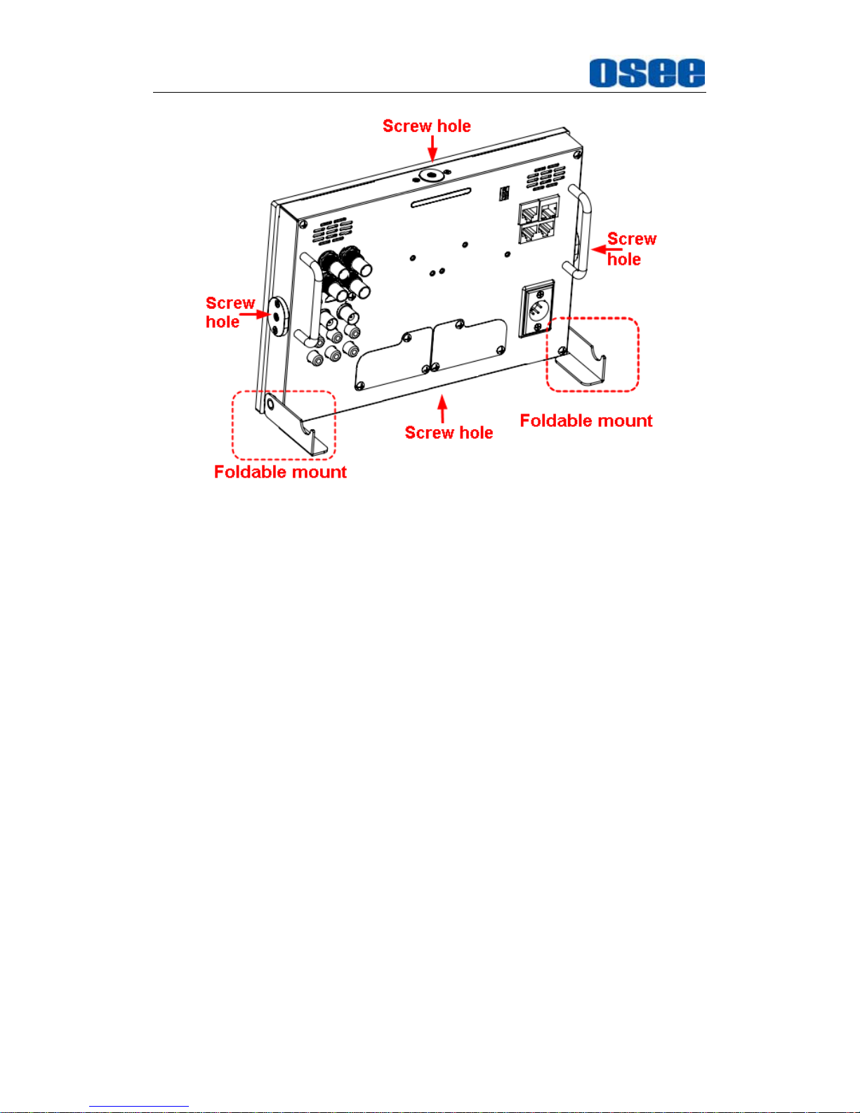
There are screw holes at the center position of each surrounding sides,
which are labeled an arrow in the following figure, and there are foldable
mounts for support the monitor.
Page 14
Network Control
8
3.
Connect required cables for signal input and output. For BNC
connections use 75Ω rated connectors.
4.
Connect power source using the included power cord.
5.
Connect the power cord to the rear panel.
6.
Fasten the power protect accessory.
7.
As a final step, turn on each screen of the PRM1014 by pressing the
corresponding power switch located on the front panel.
Page 15

PRM1014 Features
9
Chapter 4 PRM1014 Features
This chapter describes the features of PRM1014 monitor. The features of
PRM1014 monitor are as shown in Figure 4-1 after installed and powered on:
Figure 4-1 Features of PRM1014 Monitor
1. Tally light: this LED light is at the top center of the front panel, and you
can judge the monitor status by the color of Tally light. This tri-color
(red/green/amber) light is controlled through a RJ45 connector on the
rear panel.
2.
Status Information: it is displayed in the top left corner of the screen,
and includes the input channel and signal format. You can define it in
DISPLAY menu.
3.
Waveform and Vector: this is effective only for SDI signal. The
waveform and vector of the input signal are configurable in the MAIN
Menu.
4.
Area Marker: it is used to mark different area of the image. You can set
whether to display it or not and their displaying mode in MARKER menu.
5.
Safe Marker: it is used to mark different area of the image. You can set
whether to display it or not and their displaying mode in MARKER menu
Page 16
PRM1014 Features
10
6.
Center Marker: it is displayed in the center of the screen, and marks the
center of the image. You can set whether to display it or not in MARKER
menu.
7.
Audio Meter: it is displayed for audio monitoring. You can set its groups,
direction, position and mode in AUDIO menu.
8.
Timecode: it is displayed at the bottom of the image, the format is
HH:MM:SS:FF, if there is no timecode available, the monitor will display
--:--:--:--.
9.
IMD:
the IMD text displays at the bottom of the screen, the length can’t
exceed 16 characters, and you can choose letter, number or other
character for it.
10.
MUTE
The icon for MUTE is . When it is mute, this icon displays at the
bottom right position of the screen. You can set this function in function
key.
11.
Headphone Interface: The Ω icon as shown in Screen No.1 is the
headphone interface, it supports 3.5mm stereo, and the two screen
share one headphone interface.
The
Status Information
usually displays as the following situations:
"UNKNOW” appears if an unsupported signal is input.
“NO SIGNAL” appears if no signal is input.
The signal is normal, for example: 1080i59.94, NTSC, 1280X1024,
etc.
The
Status Information
for the main picture displays at the top left corner
of the screen, and the
Status Information
for the slave picture displays at
the top right corner of the screen.
The AFD information displays at the top center of the screen.
Page 17
PRM1014 Features
11
4.1 Front Panel Features
It will introduce the arrangement and the operations of the buttons in front of
the panel in the following.
4.1.1 Arrangement of Front Panel
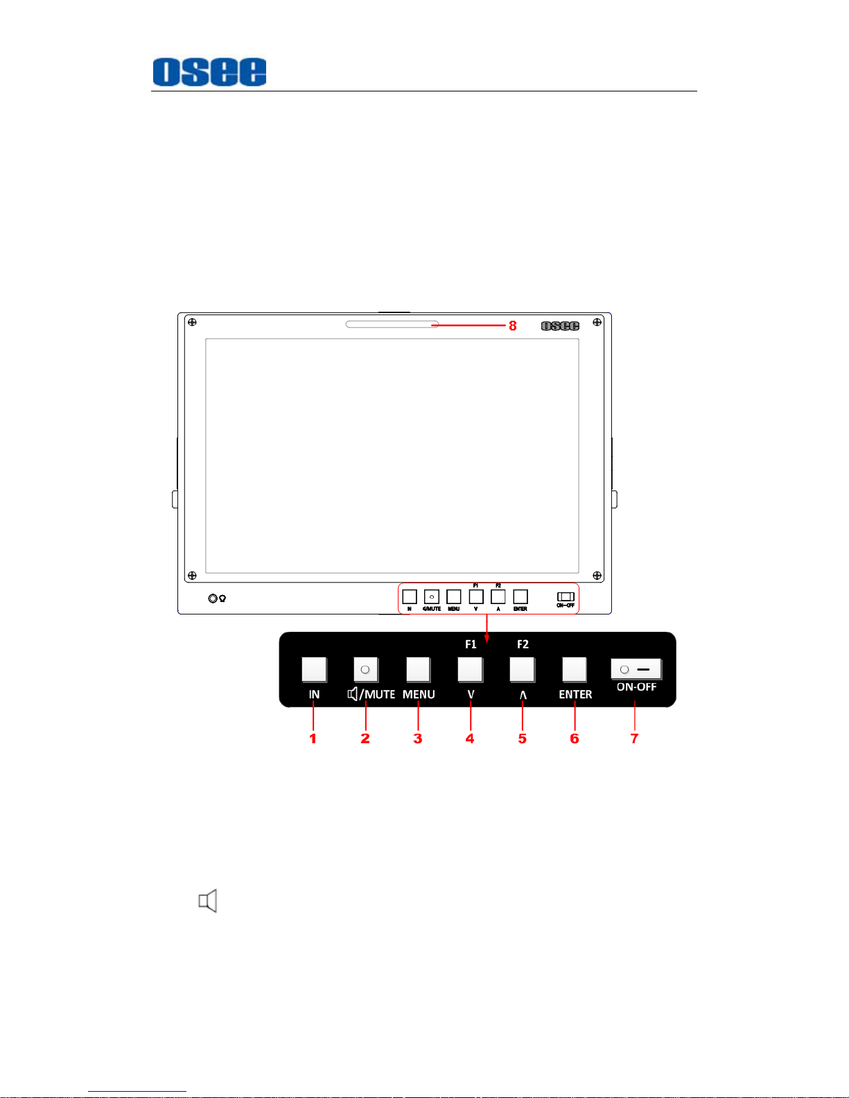
There are a series of buttons at the bottom of the screen.
Figure 4.1-1 the Buttons in Front Panel
As shown in Figure 4.1-1, the buttons labeled in numbers are described as
follows:
1. IN
2. /MUTE
3. MENU
4. F1/∨
Page 18

PRM1014 Features
12
5.
F2/∧
6. ENTER
7.
Power
8.
Tally Light(Front)
Only the
/MUTE
button has a light indicator.
4.1.2 Operation of Front Panel
The functionality and usage of the buttons at the front panel are as
follows:
1. IN
Select the input signal. Press this button to display the source menu at the
right top corner of the screen, as shown in Figure 4.1-2. Use it to select an
input signal source, press it again to toggle among these input signal
items.
Figure 4.1-2 Source Menu
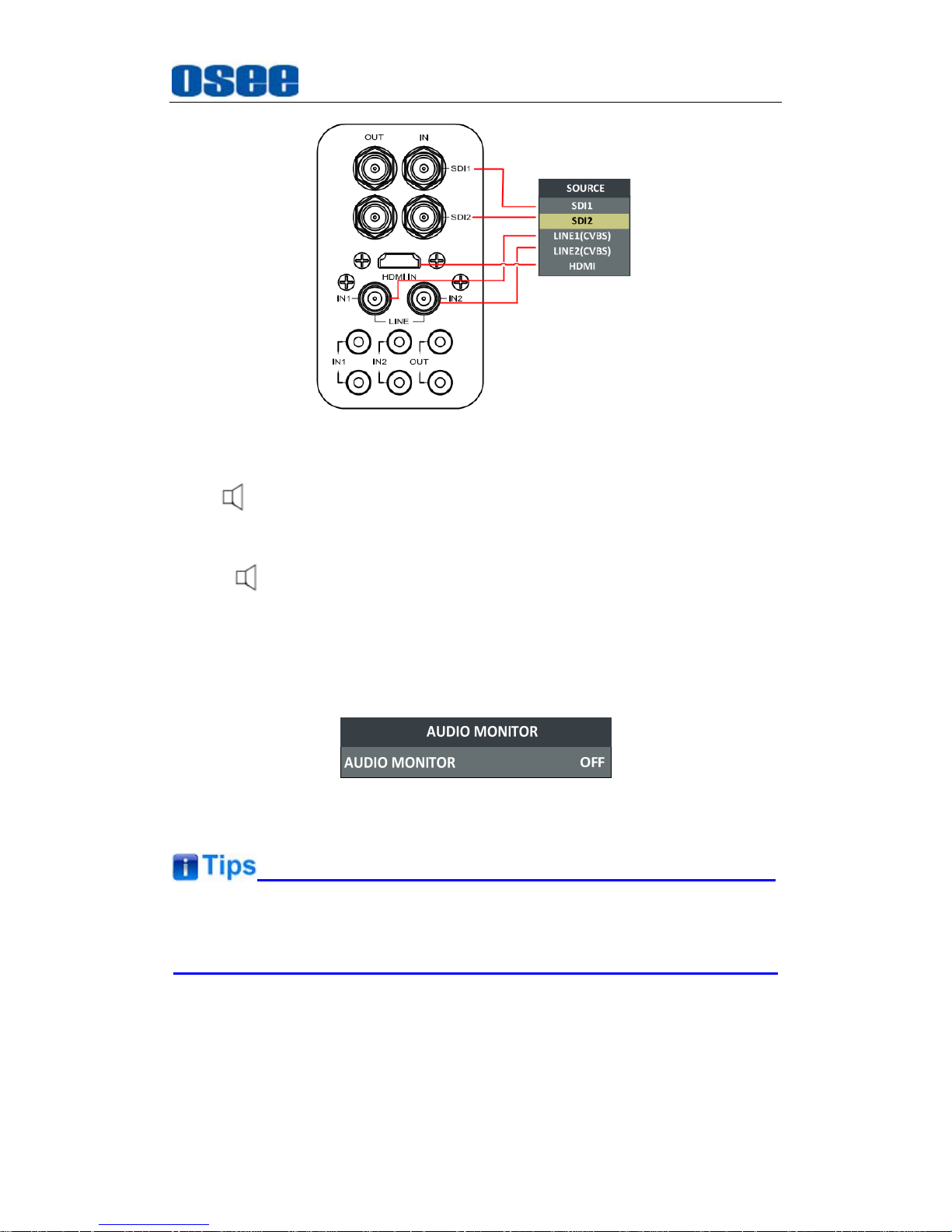
The one-to-one correspondence between the signals in the source menu
list and the interfaces in the back panel are shown in Figure 4.1-3:
Page 19
PRM1014 Features
13
Figure 4.1-3 Correspondence between Source Menu and Interface
2. /MUTE
This button can achieve the following two functions:
: Audio monitor button. Toggle this button to enable or disable the
audio monitor, and the light in the button will indicate the status of
audio monitoring. When the light is on, the audio is monitoring, and
when the light is off, it is mute. The volume is adjusted in adjust menu.
MUTE
: Audio mute button. Toggle this button to enable or disable the
audio monitor.
Figure 4.1-4 Audio Monitor Menu
After you have loaded the Audio Monitor Menu, it will be closed
automatically if you do nothing operation with it in 10s.
3. MENU
It is used to activate the Main menu. Press this button to do some
operations with the Main menu, it includes the following operations:
Display the Main menu
Page 20
PRM1014 Features
14
Back to the higher level menu
Quit the Main menu
Refer to “5.2 Menu Settings” for detail about the main menu operations.
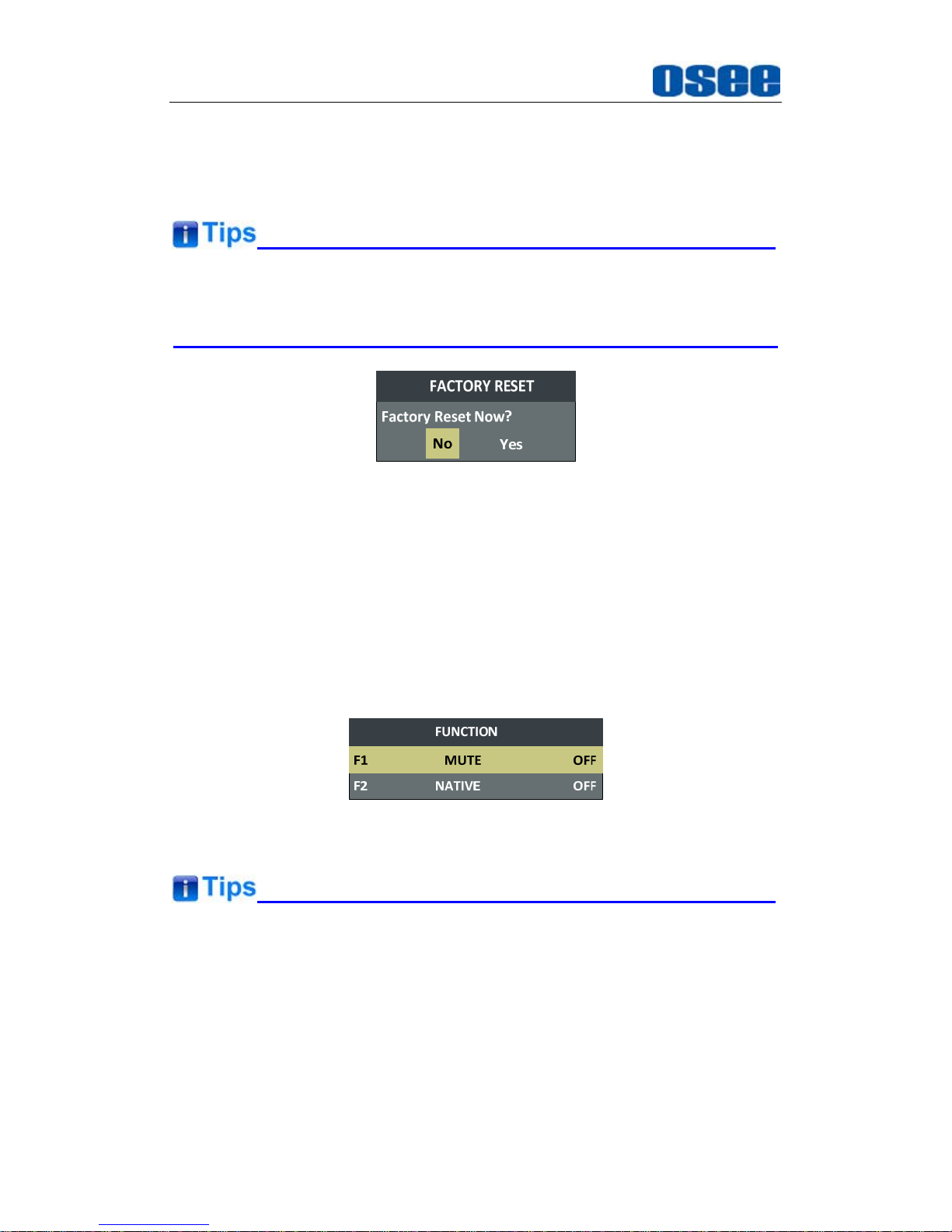
Press and hold the
MUTE+ENTER
button for 3s can reset the menu
settings to factory originals, as shown in Figure 4.1-5.
Figure 4.1-5 Reset Menu List
4. F1/∨
This button can achieve the following two functions:
F1:
F1 function button. Press F1 to display the function menu list in the
center of the screen, as shown in Figure 4.1-6. Toggle F1 button to
change the value related to this function.
∨: it is
Down
button when working with
MENU
. Toggle this button to
select the next item or decrease the number.
Figure 4.1-6 Function Menu List
After you have loaded the function menu list, it will be closed automatically
if you do nothing operation with it in 10s.
If the value related to the function button can’t be modified, the value shows
in blue.
Use
FUNCTION KEY
menu to assign F1 and F2. You can assign F1/F2 the
function from among: SCAN, NATIVE, ASPECT, BLUE ONLY, MONO,
Page 21

PRM1014 Features
15
MARKER, H/V DELAY, AUDIO METER, FAST MODE, TC, IMD, MUTE,
PBP, CC, FREEZE, WIN SELECT, FOCUS ASSIST, LUMA ZOOM CHECK,
UNDEF. Refer to "5.1.9 FUNCTION KEY Menu" for the details.
5. F2/∧
This button can achieve the following two functions:
F2:
F2 function button. Press F2 to display the function menu list in the
center of the screen, toggle F2 button to change the value related to
this function.
∧: it is Up button when working with
MENU
. Toggle this button to
select the next item or increase the number.
Figure 4.1-7 Function Menu List
6. ENTER
This button can achieve the following two situations:
Work with the Main MENU
: when working with the Main menu,
ENTER button achieve the following functions:
Enter into the next level menu: press
ENTER
button, you will enter
into the menu item as this relationship: the Main menu list
sub-menu list sub-menu value list, the current editable object is
in yellow control icon;
Confirm the value selection: press
ENTER
button to confirm the
value selection.
Adjust Menu:
when not displaying the Main menu, press
ENTER
button to display the adjust menu list, as shown in Figure 4.1-8, toggle
among these menu items: VOLUME, BRIGHTNESS, CONTRAST,
CHROMA.
Figure 4.1-8 Adjust Menu List
After displaying the Adjust menu, press
∧
(Up)
or
∨
(Down)
button to
adjust the menu value, and then press
ENTER
button to confirm the value
Page 22
PRM1014 Features
16
selection.
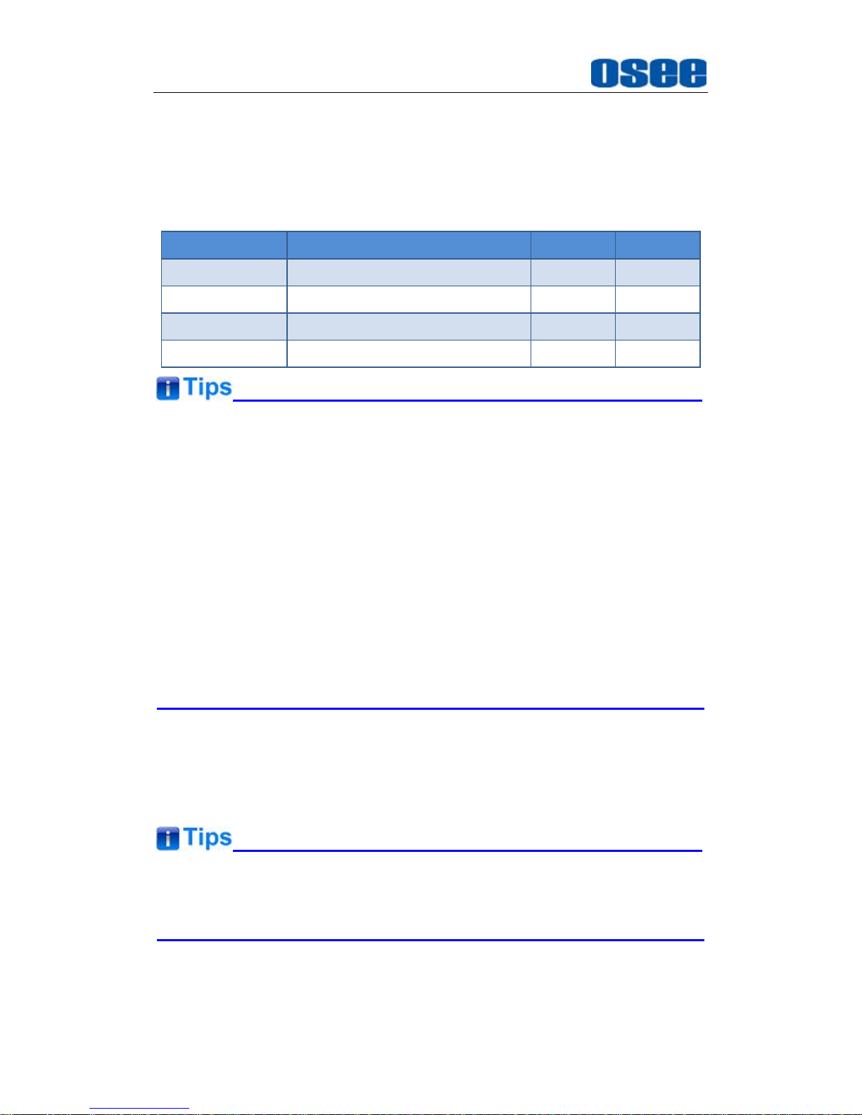
The relationship of the menu items and their range is shown in Table
4.1-1:
Table 4.1-1 The Description of Adjust Menu Items
Adjust Menu Description Range Default
VOLUME Adjust the volume 0~31dB 16
BRIGHTNESS Adjust the image brightness 0~100 50
CONTRAST Adjust the image contrast 0~100 50
CHROMA Adjust the image monochroma 0~100 50
Set these parameter value in the following position: BRIGHTNESS,
CONTRAST, CHROMA.
In Adjust Menu List on screen when pressing Enter key.
In Adjust menu of network control page.
After you have loaded the adjust menu list, it will be closed automatically if
you do nothing operation with it in 10s.
The main menu, the adjust menu, the function menu and the input signal
selection list of a screen may not be shown all simultaneously.
7. Power
Used to power on or standby, and the light in the button will indicate the
status of the power. If the light is green, the monitor is powered on, if the
light is flashing, the monitor is standby.
When the device is standby, cut off the power and restart the device, the
status of the device will be normal but not standby.
Page 23
PRM1014 Features
17
4.2 Rear Panel Features
It will introduce the arrangement and the operations of the interfaces in rear of
the panel in the following.
4.2.1 Arrangement of Rear Panel
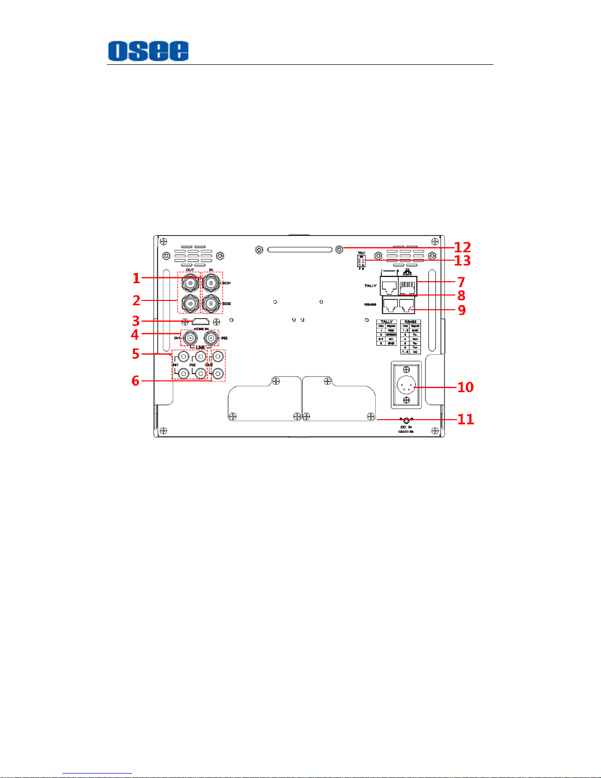
As shown in Figure 4.2-1, there are various input and output interfaces at
the rear panel of PRM1014 monitor.
Figure 4.2-1 The Rear Panel of PRM1014 Monitor
The interfaces numbered from 1 to 8 in red dotted rectangle are described
as follows:
1. Video Input
2. Video Output
3. HDMI Input
4. Video Input
5. Audio Output
6. Audio Input
7. Ethernet
8. Tally Input
9. RS485 In/Out
10. Power Input
Page 24

PRM1014 Features
18
11.
Battery Plate
12.
Tally Light(Back)
13. Tally Switch
4.2.2 Operations of Rear Panel
The details of these interfaces at the rear panel are described as follows:
1. Video Input Interface (BNC)
It provides two SDI input interfaces, one is labeled as SDI1 IN, and the
other is SDI2 IN, 800mVp-p +/-10%.
2. Video Output Interface (BNC)
It provides two SDI output interfaces. One is labeled as SDI1 OUT, the
other is SDI2 OUT, 800mVp-p +/-10%, active loop.
3. HDMI
It provides one HDMI input interface, HDMI Type-A connector with a
fastener.
4. Video Input Interface (BNC)
It provides two SDI input interfaces. One is labeled as LINE IN1, and the
other is LINE IN2, 1Vp-p +/-3dB, sync negative.
5. Audio Output interface
It provides two audio output interfaces, 5dBu, impedance≤500Ω, RCA
connector.
6. Audio Input interface
It provides four audio input interfaces, 5dBu, impedance≥47K, RCA
connector.
7.
Ethernet (RJ-45)
It provides one 10/100M Ethernet connector. It is used to connect with a
computer to modify the network settings.
8.
Tally(DB9)
It controls the LED tally light.
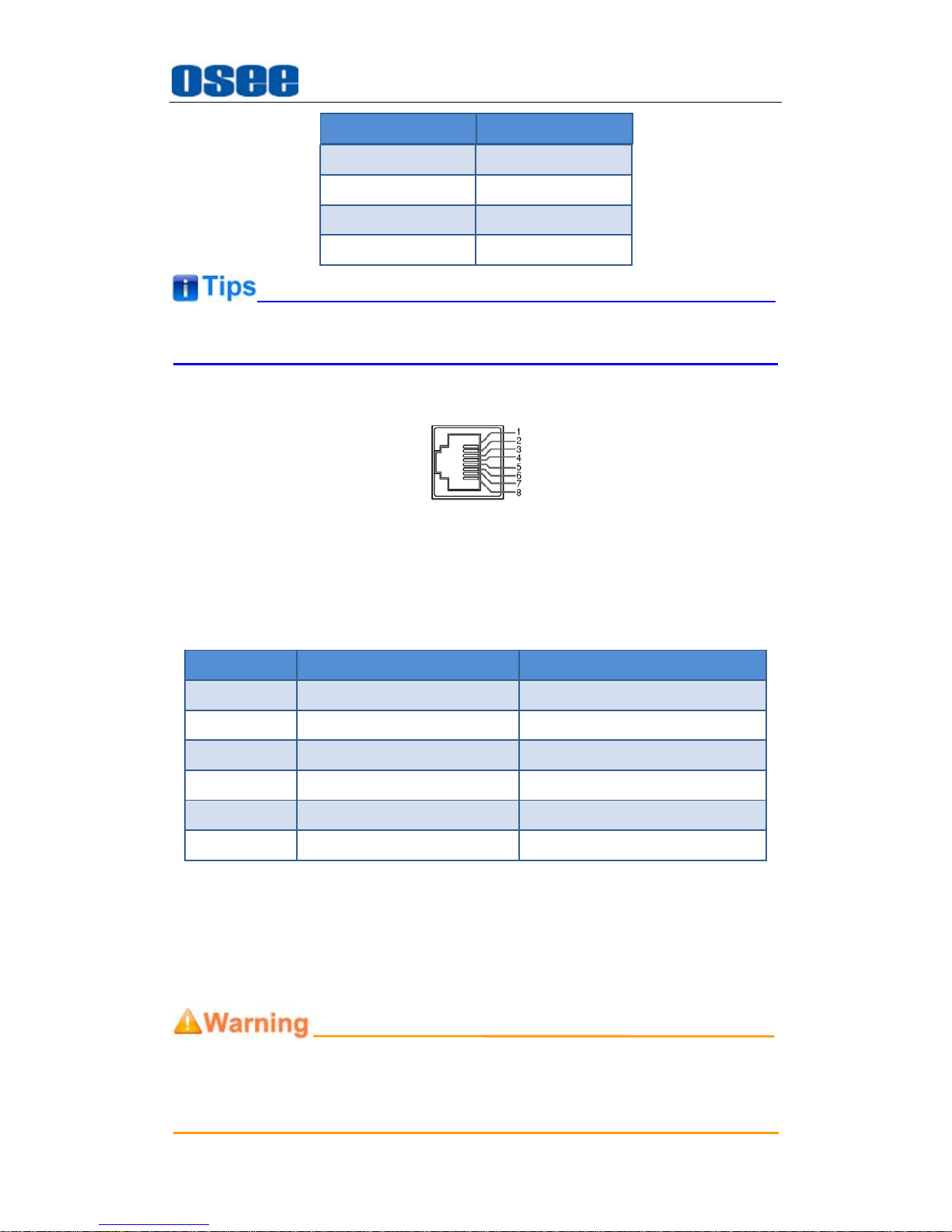
The relationship of the pins of Tally interface and its channel value is
shown in Table 4.2-1.
Table 4.2-1 The Relationship of Tally Input Pins and Channel Values
Page 25
PRM1014 Features
19
Pin 1 RED
Pin 2 GREEN
Pin 3~7 NC
Pin 8 GND
Tally light is in working status when grounding.
9.
IN/ OUT RS485 Interface (RJ-45)
Support for dynamic UMD and updating the new firmware.
The Comparison of Pins and Input/output connectors for RS485 is
shown as in Table 4.2-2:
Table 4.2-2 The Comparison of Pins and Input/output connectors for
RS485
PIN No. RS485 IN Terminal Signal RS485 OUT Terminal Signal
1,2 GND GND
3 Tx- Tx-
4 Rx+ Rx+
5 Rx- Rx-
6 Tx+ Tx+
7,8 NC NC
10.
Power Input
It provides a 4-pins cannon power input interface, the specification is
5A12VDC. The corresponding indicator is at the front panel. If the light
is green, the monitor is powered on, if the light is flashing, the monitor is
standby, and if the light is off, the monitor is powered off.
Only use the adapter and the power cord specified by the manufacture for
your safety
!
Pin No. Channel Value
Page 26
PRM1014 Features
20
11.
Battery Plate
It provides battery plate as optional accessory for PRM1014, thus, you
can use external batteries as the power supply for PRM1014, and you can
select two types according to the amount of the battery plates: one battery
plate or two battery plates. Refer to “Chapter 7 Specifications” for the
details about the optional accessories.
12. Tally Light(Back)
There is a back tally light at the top of the rear panel, and controlled by
combination relationship of Tally input and tally switch.
13. Tally Switch
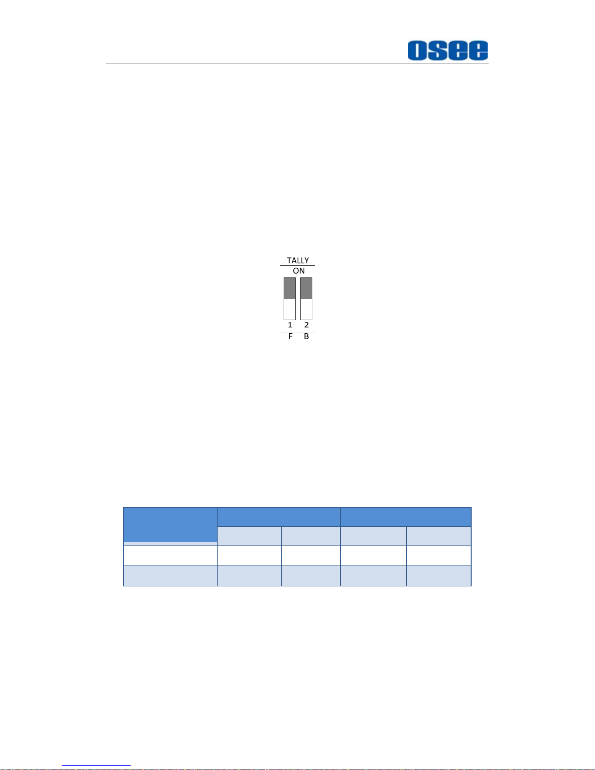
There is a group of tally dip switch, as shown in Figure 4.2-2:
Figure 4.2-2 Tally Switch of PRM1014 Monitor
The dip is white, and it is on the ON character side that the corresponding
tally light will be lit up.
The front Tally light is controlled by No.1 Dip labeled with a letter F for
short, and the back Tally light is controlled by No.2 Dip labeled with a letter
B. When you dial the two dips to different position, the corresponding tally
light will be in different status, the relationship is shown in Table 4.2-3:
Table 4.2-3 The Relationship of Tally Light and Tally Switch
Tally Switch
Screen 1 Screen 2
ON OFF ON OFF
Tally Light-Front
Light ON Light OFF
Light OFF Light OFF
Tally Light-Back
Light OFF Light OFF
Light ON Light OFF
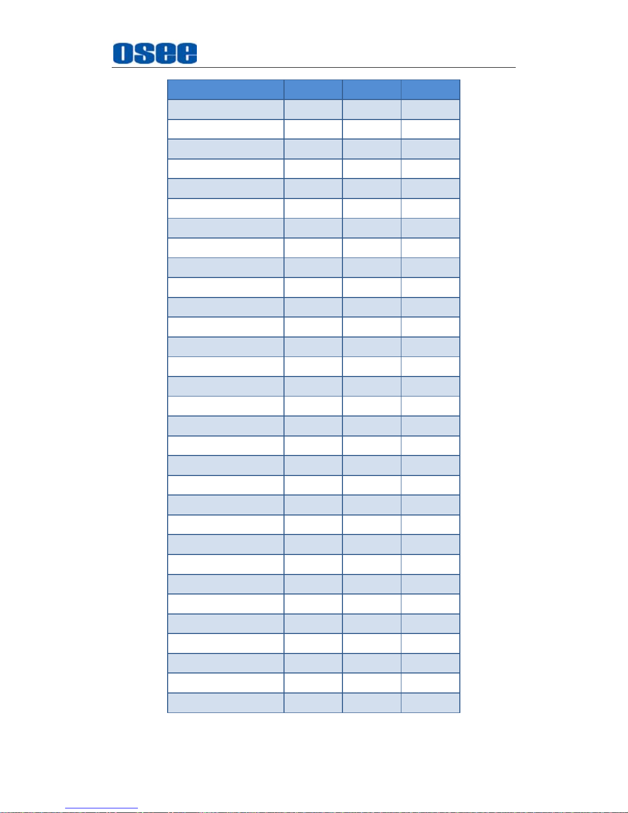
4.3 Supported Signal Format
The supported signal format for this device is as shown in Table 4.3-1:
Table 4.3-1 Supported Signal Format
Page 27
PRM1014 Features
21
SDI VIDEO HDMI
PAL
NTSC
480I60/59.94
576I50
480P60/59.94
576P50
720P24/23.97
720P25
720P30/29.97
720P50
720P60/59.94
1080SF24/23.97
1035I60/59.94
1080I50
1080I60/59.94
1080P24/23.97
1080P25
1080P30/29.97
1080P50
1080P60/59.94
VGA(640X480)
SVGA(800X600)
XGA(1024X768)
SXGA(1280X1024)
WXGA(1360X768)
WXGA+(1440X900)
WXGA+(1400X1050)
UXGA(1600X1200)
UXGA+(1680X1050)
WUXGA(1920X1080)
WUXGA(1920X1200)
Page 28

22
Page 29
Functionality of the Main Menu
23
Chapter 5 Functionality of the Main Menu
This chapter describes the structure and functionality of the main menu, and
introduces how to modify and customize the menu settings.
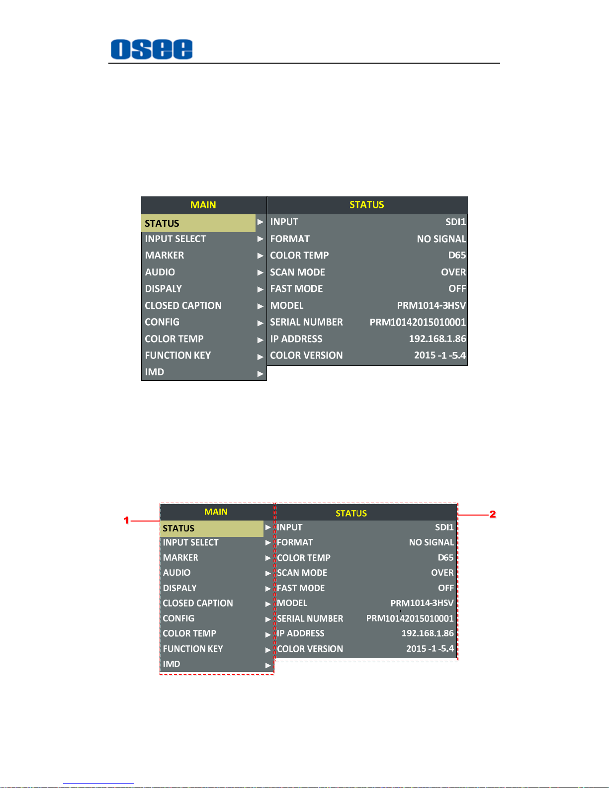
The main menu includes the following menu items, as shown in Figure5-1.
Figure 5-1 Main Menu
5.1 Main Menu
Press the MENU button at the bottom of the front panel, the main menu is
displayed at the top left corner of the screen, as shown in Figure 5.1-1:
Figure 5.1-1 the Structure of the Main Menu
Page 30
Functionality of the Main Menu
24
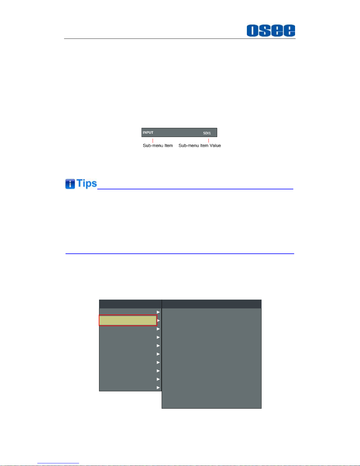
The menu interface is divided into three parts:
1. Main Menu List: it contains the several sub-menu items. The title of this
list is MAIN. Press Up(∧) or Down(∨) to access the corresponding
menu item.
2. Sub-menu value list: as shown in Figure 5.1-2, it lists the control icon,
sub-menu item and the value of the item. After pressing Menu button,
press Up(∧), Down(∨) button and Enter button to modify the value of
the sub-menu. Refer to “5.2 Menu Settings” for details.
Figure 5.1-2 the Sub-menu Value List
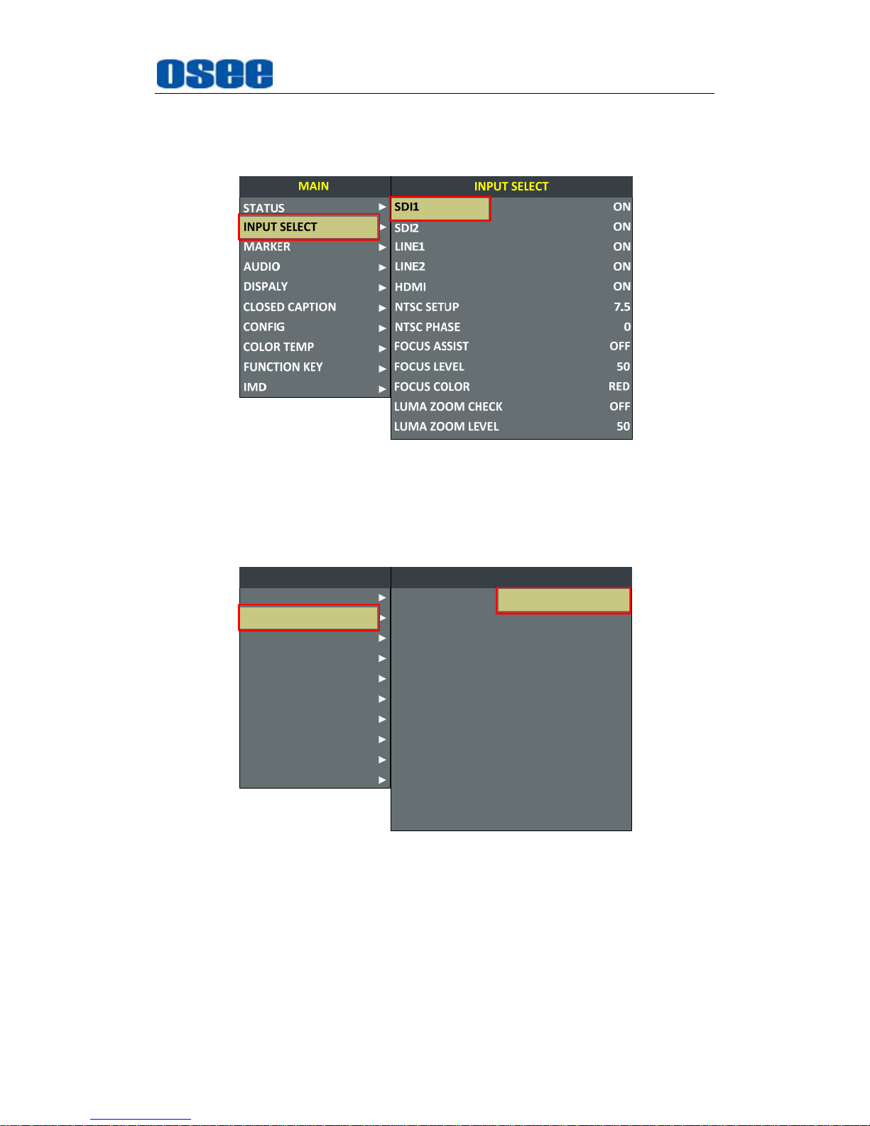
The sub-menu item is selected when the control icon which is in yellow
highlight is at the back of the item name.
The sub-menu item value is editable when the control icon which is in
yellow highlight is at the back of the item value.
The control icon of the main menu has the following status when in different
positions, as shown in the red rectangle of the following figures:
when in the main menu, it shows that this menu item is selected, as
shown in Figure 5.1-3:
CLOSED CAPTION
MARKER
AUDIO
DISPALY
CONFIG
COLOR TEMP
FUNCTION KEY
IMD
MAIN
STATUS
INPUT SELECT
NTSC SETUP
SDI1
SDI2
LINE1
LINE2
HDMI
NTSC PHASE
INPUT SELECT
7.5
ON
ON
ON
ON
ON
0
LUMA ZOOM CHECK
FOCUS ASSIST
FOCUS LEVEL
FOCUS COLOR
LUMA ZOOM LEVEL
OFF
OFF
50
RED
50
Figure 5.1-3 A Main Menu Item Is Selected
Page 31
Functionality of the Main Menu
25
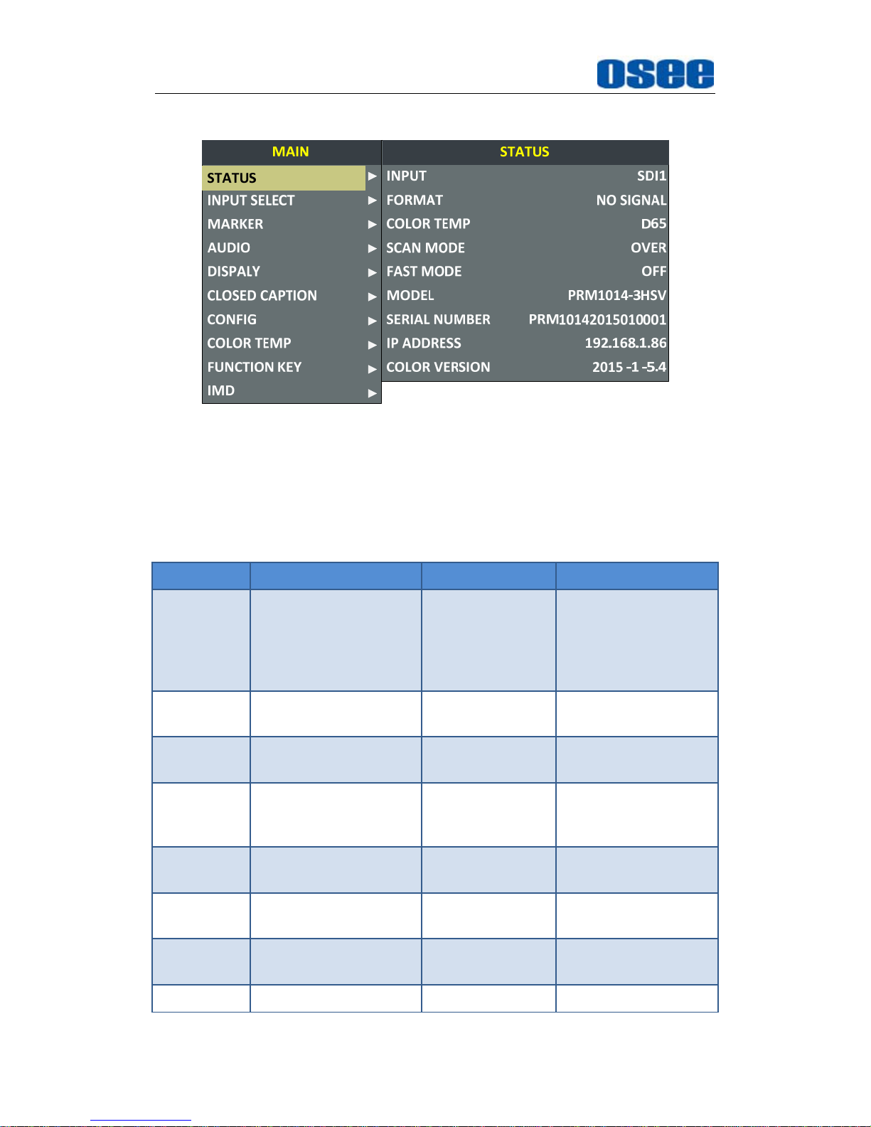
when in the sub-menu item, it shows that this sub-menu item is
selected, and the control icon is displayed as a yellow rectangle in front
of it, as shown in Figure 5.1-4:
Figure 5.1-4 A Sub-menu Item Is Selected
when in the sub-menu item value, it shows that this sub-menu item
value is selected, and the value is displayed in yellow, as shown in
Figure 5.1-5:
CLOSED CAPTION
MARKER
AUDIO
DISPALY
CONFIG
COLOR TEMP
FUNCTION KEY
IMD
MAIN
STATUS
INPUT SELECT
NTSC SETUP
SDI1
SDI2
LINE1
LINE2
HDMI
NTSC PHASE
INPUT SELECT
7.5
ON
ON
ON
ON
ON
0
LUMA ZOOM CHECK
FOCUS ASSIST
FOCUS LEVEL
FOCUS COLOR
LUMA ZOOM LEVEL
OFF
OFF
50
RED
50
Figure 5.1-5 A Sub-menu Item Value Is Selected
The following will introduce the contents and functionality of these sub-menu
items in sorts.
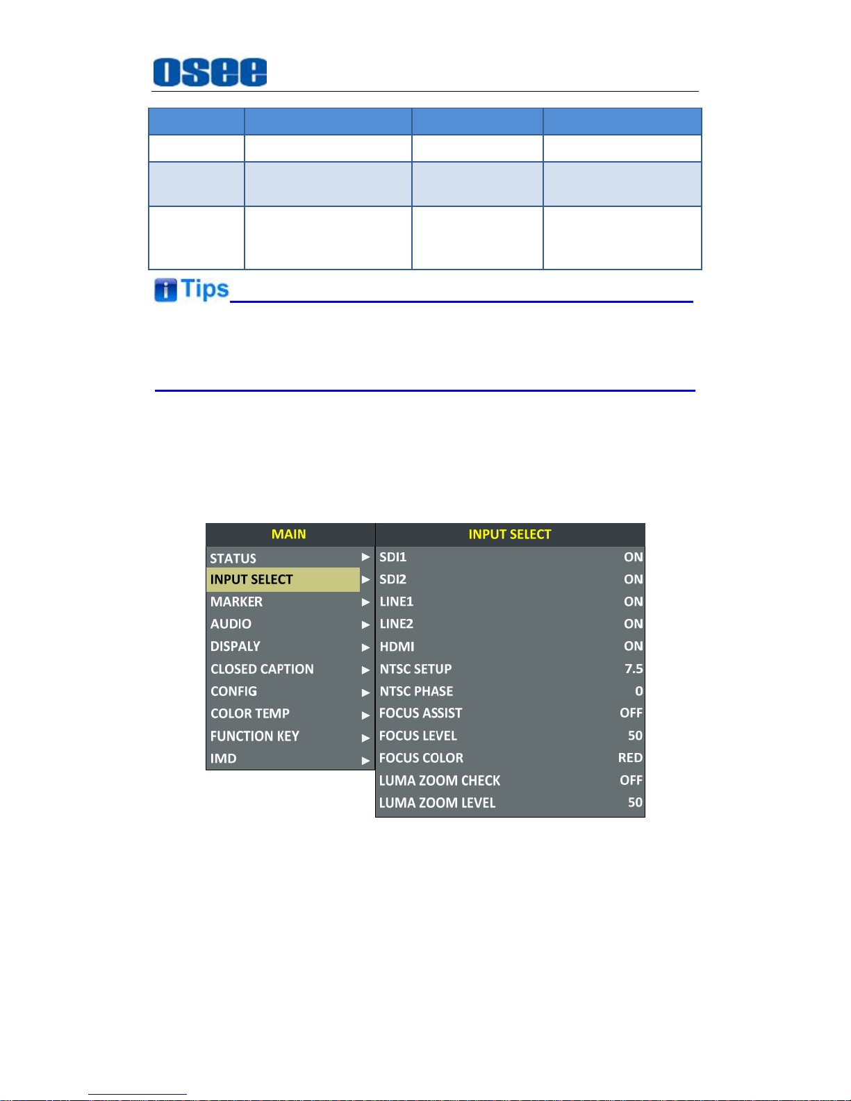
5.1.1 STATUS Menu
The STATUS menu items are used to describe the current status
Page 32
Functionality of the Main Menu
26
information of the monitor, the menu items are as shown in Figure 5.1-6:
Figure 5.1-6 STATUS Menu
The relationship of Items, Default Value, Domain Range and Description
of the sub-item is shown in Table 5.1-1:
Table 5.1-1 The Description of STATUS Menu Items
Items Default Value Domain Range Description
INPUT SDI1
SDI1
SDI2
LINE1(CVBS)
LINE2(CVBS)
HDMI
Show the Input
format
FORMAT NO SGINAL --
Show the format of
the input signal
COLOR
TEMP
D65 --
Show the color
temperature.
SCAN
MODE
NORMAL
NORMAL
OVER
UNDER
Show the scan mode.
FAST
MODE
OFF OFF/ON Show the fast mode.
SD ASPECT 16:9 16:9/4:3
Show the screen
Aspect Ratio.
MODEL PRM1014-3HSV --
Show the production
model.
SERIAL PRM10142015010001 -- Show the serial
Page 33
Functionality of the Main Menu
27
Items Default Value Domain Range Description
NUMBER number.
IP
ADDRESS
192.168.1.86 -- Show the IP address.
COLOR
VERSION
2015-1-5.4 --
Show the color
version according to
its adjusted date.
The sub-menu values in
STATUS
menu can’t be modified, they are
displayed the actual status of the monitor.
5.1.2 INPUT SELECT Menu
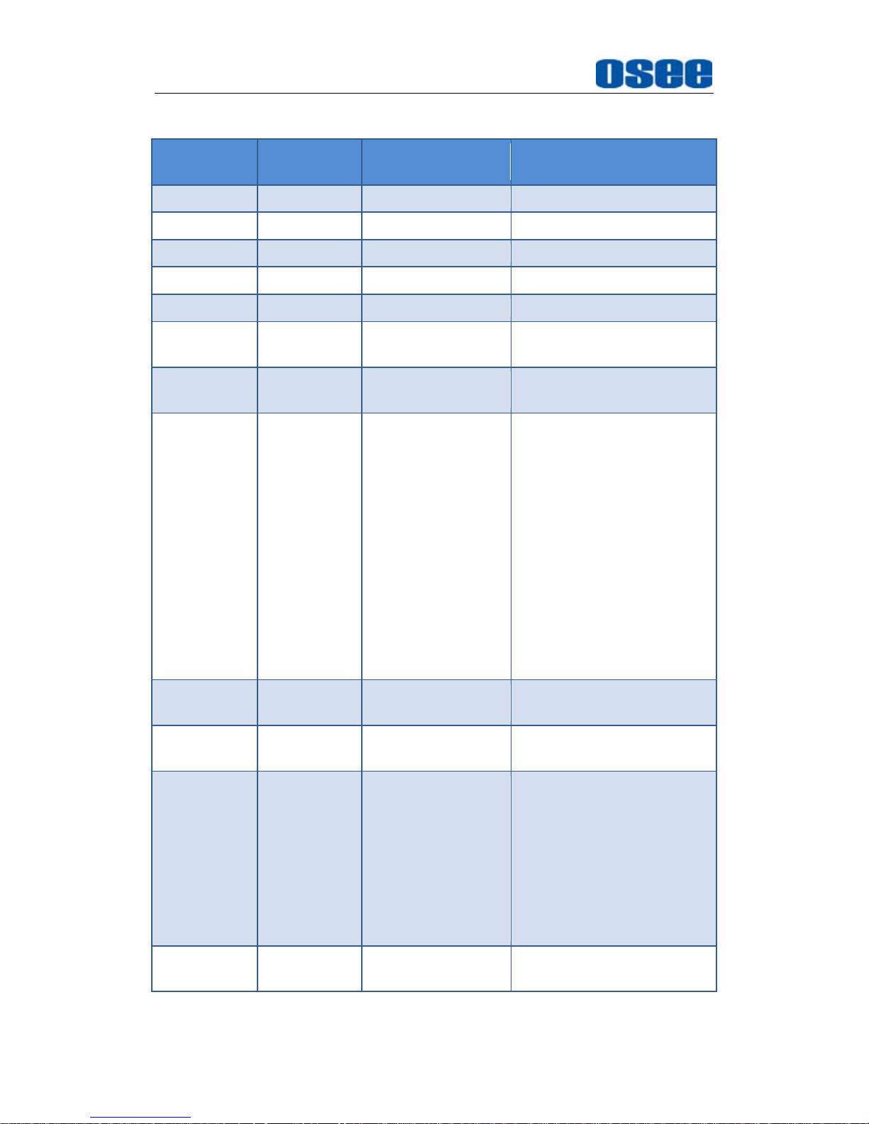
The INPUT SELECT menu items are used to set the source of the input
signals, the menu items are as shown in Figure 5.1-7:
Figure 5.1-7 INPUT SELECT Menu
The relationship of Items, Default Value, Domain Range and Description of the
sub-item is shown in Table 5.1-2:
Page 34
Functionality of the Main Menu
28
Table 5.1-2 The Description of INPUT SELECT Menu Items
Items
Default
Value
Domain Range Description
SDI1 ON ON/OFF Enable/Disable SDI1 input
SDI2 ON ON/OFF Enable/Disable SDI2 input
LINE1 ON ON/OFF Enable/Disable LINE1 input
LINE2 ON ON/OFF Enable/Disable LINE2 input
HDMI ON ON/OFF Enable/Disable HDMI input
NTSC
SETUP
7.5 0/7.5 Select the NTSC mode
NTSC
PHASE
0 -50~50 Set the NTSC phase
FOCUS
ASSIST
OFF
OFF
STANDARD:
An image with
sharpened
edges is
displayed.
COLOR:
Displays the
intensified
areas of images
with color
selected in
FOCUS
COLOR.
Enable/Disable the focus
assist function, and set the
focus assist mode.
FOCUS
LEVEL
50 0~100
Set the level of edge
sharpening.
FOCUS
COLOR
RED RED/GREEN/BLUE
Set the color for the
sharpened edge.
LUMA ZOOM
CHECK
OFF ON/OFF
Enable/Disable the luma
zoom check function that
will compare the signal
luminance with the LUMA
ZOOM LEVEL, and fill the
relevant image area whose
luminance is higher than
the LUMA ZOOM LEVEL
with a zebra pattern.
LUMA ZOOM
LEVEL
50 0~100
Set the level of detecting
luminance.
1. FOCUS ASSIST
Page 35
Functionality of the Main Menu
29
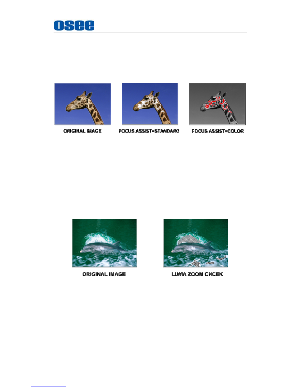
The FOCUS ASSIST function is used to display images on the screen with
sharpened edges to help camera focus operation. The sharpened edges
are the compared area whose luminance is beyond the reference level,
and the edges are displayed in the pointed color.
For example, set the
FOCUS COLOR
as RED, and set the
FOCUS
LEVEL
as 80, the compared results are as shown Figure 5.1-8:
Figure 5.1-8 Illustration for FOCUS ASSIST Function
2. LUMA ZOOM CHECK
The LUMA ZOOM CHECK function is used to display images on the
screen with a zebra pattern to adjust the camera exposure parameter. It
will compare the signal luminance with the
LUMA ZOOM LEVEL
, and fill
the relevant image area whose luminance is higher than the
LUMA ZOOM
LEVEL
with a zebra pattern.
For example, set the
LUMA ZOOM LEVEL
as 80, the compared results
are as shown in Figure 5.1-9, the special area is filled with a zebra pattern.
Figure 5.1-9 Illustration for LUMA ZOOM CHECK Function
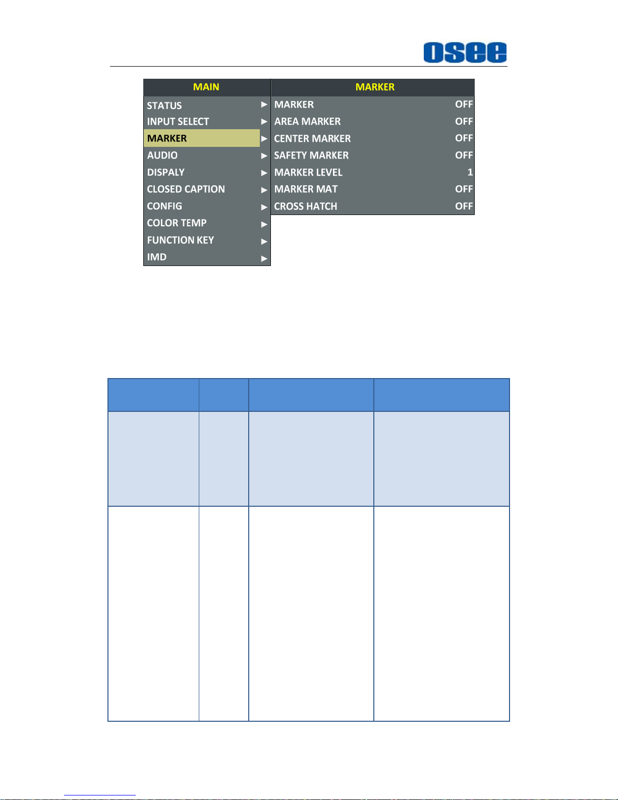
5.1.3 MARKER Menu
The MARKER menu items are used to adjust the marker parameters, the
menu items are as shown in Figure 5.1-10:
Page 36
Functionality of the Main Menu
30
Figure 5.1-10 MARKER Menu
The relationship of Items, Default Value, Domain Range and Description
of the sub-item is shown in Table 5.1-3:
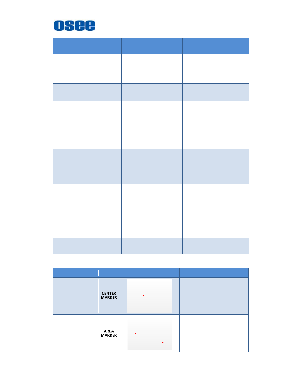
Table 5.1-3 The Description of MARKER Menu Items
Items
Default
Value
Domain Range Description
MARKER OFF OFF/ON
Set whether to show all of
the markers.
It is the main switch for
area marker, center
marker and safety
marker.
AREA MARKER OFF
when the display
aspect is 16:9, images
show with the following
scale:
OFF: close area
marker
4:3
15:9
14:9
13:9
1.85:1
2.35:1
when the display
aspect is 4:3, images
show with the following
Select the area marker
aspect ratio according to
the display aspect ratio.
Page 37
Functionality of the Main Menu
31
Items
Default
Value
Domain Range Description
scale:
OFF: close area
marker
16:9
CENTER
MARKER
OFF OFF/ON
Set whether to show the
center marker
SAFETY
MARKER
OFF
OFF
80%
85%
88%
90%
93%
95%
Set the safety area size
according to the aspect
ratio and scan mode.
MARKER
LEVEL
1
1: 50%
2: 75%
3: 100%
Set the luminance of
marker line, including
safety marker, center
marker, area marker and
cross hatch.
MARKER MAT OFF
OFF: Normal
background, use
line for area marker
edge only
HALF: 50%
Background
brightness
BLACK: all black
Set the transparency of
area marker mat.
CROSS HATCH OFF OFF/ON
Set whether to show the
cross hatch.
Markers
Marker Illustration Description
CENTER
MARKER
This marker enables
easier checking the center
portion’s focus.
AREA MARKER
This marker displays two
lines to identify an area
with a specified ratio.
Page 38
Functionality of the Main Menu
32
Marker Illustration Description
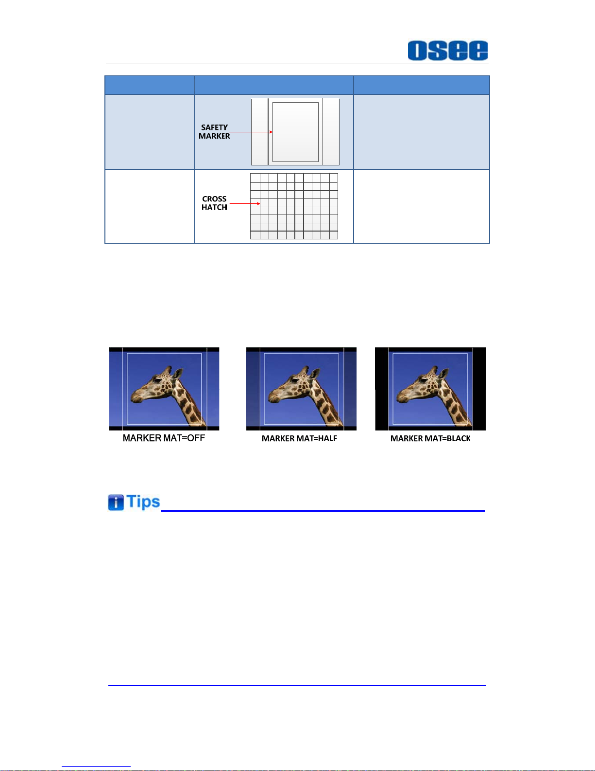
SAFETY
MARKER
This marker displays a
rectangle to identify the
safety area with a
specified percentage.
CROSS HATCH
This marker displays
multiple vertical and
horizontal lines to help
when users check the
composition of a picture.
MARKER MAT
The marker mat marks the outside area of the marker display with the
appointed transparency.
For example, set ASPECT as 16:9, AREA MARKER as 4:3, and SAFETY
AREA as 95%, then, the comparison of the three MARKER MATs are as
shown in Figure 5.1-11:
Figure 5.1-11 MARKER MAT
All markers will be hidden in the following modes though the corresponding
marker is enabled (the value is not OFF): NATIVE, H/V DELAY, PBP.
The AREA MARKER, CENTER MARKER and SAFETY MARKER feature
are available only when the MARKER item is set to ON.
The safety marker area will change with the area marker.
The cross hatch lines will display only in the single image or in PIP mode
when
CROSS HATCH
is ON.
Page 39
Functionality of the Main Menu
33
5.1.4 AUDIO Menu
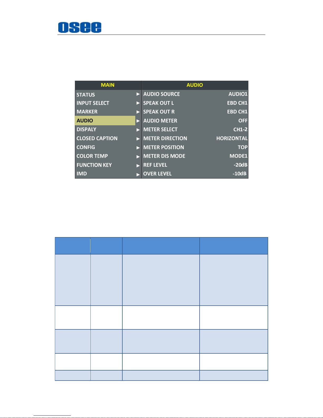
The AUDIO menu items are used to adjust the audio parameters, the
menu items are as shown in Figure 5.1-12:
Figure 5.1-12 AUDIO Menu
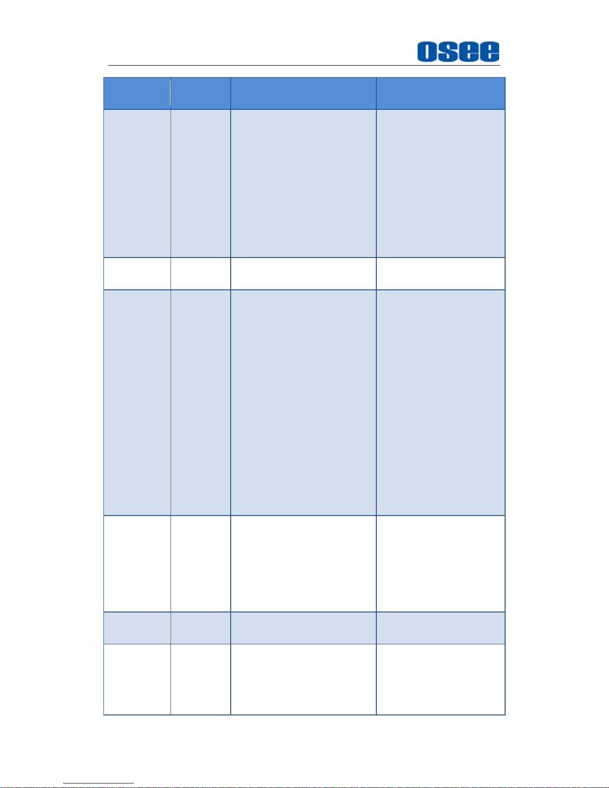
The relationship of Items, Default Value, Domain Range and Description
of the sub-item is shown in Table 5.1-4:
Table 5.1-4 The Description of AUDIO Menu Items
Items
Default
Value
Domain Range Description
AUDIO
SOURCE
EDB
EDB: embedded signal
AUDIO1: external
signal1
AUDIO2: external
signal2
UNDEF: no signal
Select the audio source.
When there is no sync in
and the input signal is
not HDMI/SDI1/SDI2,
you can select only
UNDEF, AUDIO1 or
AUDIO2.
SPEAK
OUT L
EBD CH1
When the audio source is
EBD, the range of this item
is EDB CH1~ EDB CH16.
Left speaker, select a
channel according to the
type of audio source.
SPEAK
OUT R
EDB CH2
When the audio source is
EBD, the range of this item
is EDB CH1~ EDB CH16.
Right speaker, select a
channel according to the
type of audio source.
AUDIO
METER
OFF OFF/ON
Set whether to display
the audio meter.
METER CH1-2
CH1-2
Select a meter display
Page 40
Functionality of the Main Menu
34
Items
Default
Value
Domain Range Description
SELECT
G1
G2
G3
G4
G1+G2
G1+G3
G1+G4
G2+G3
G2+G4
G3+G4
G1-G4
mode. Each G* contains
four channels, and each
CH* means a channel
with number.
METER
DIRECTION
VERTICAL
VERTICAL/HORIZONTAL
Select the displayed
direction of audio meter.
METER
POSITION
BOT
LEFT/
BOTTOM
When the value of METER
DIRECTION is VERTICAL,
you can choose the
followings for Meter
Position:
BOT LEFT: bottom left
BOT RIGHT: bottom
right
TOP RIGHT: top right
TOP LEFT: top left
When the value of METER
DIRECTION is
HORIZONTAL, you can
choose the followings for
Meter Position:
BOTTOM
TOP
Select the displayed
position of audio meter.
METER DIS
MODE
MODE1
MODE1: simple audio
meter
MODE2: audio meter
with channel number
MODE3: audio meter
with channel number
and dB value
Select the displayed
mode for audio meter.
REF LEVEL -20dB -20dB/-18dB
Select the reference
level
OVER
LEVEL
-10dB
-10dB
-8dB
-6dB
-4dB
-2dB
Select the overload level
Page 41
Functionality of the Main Menu
35
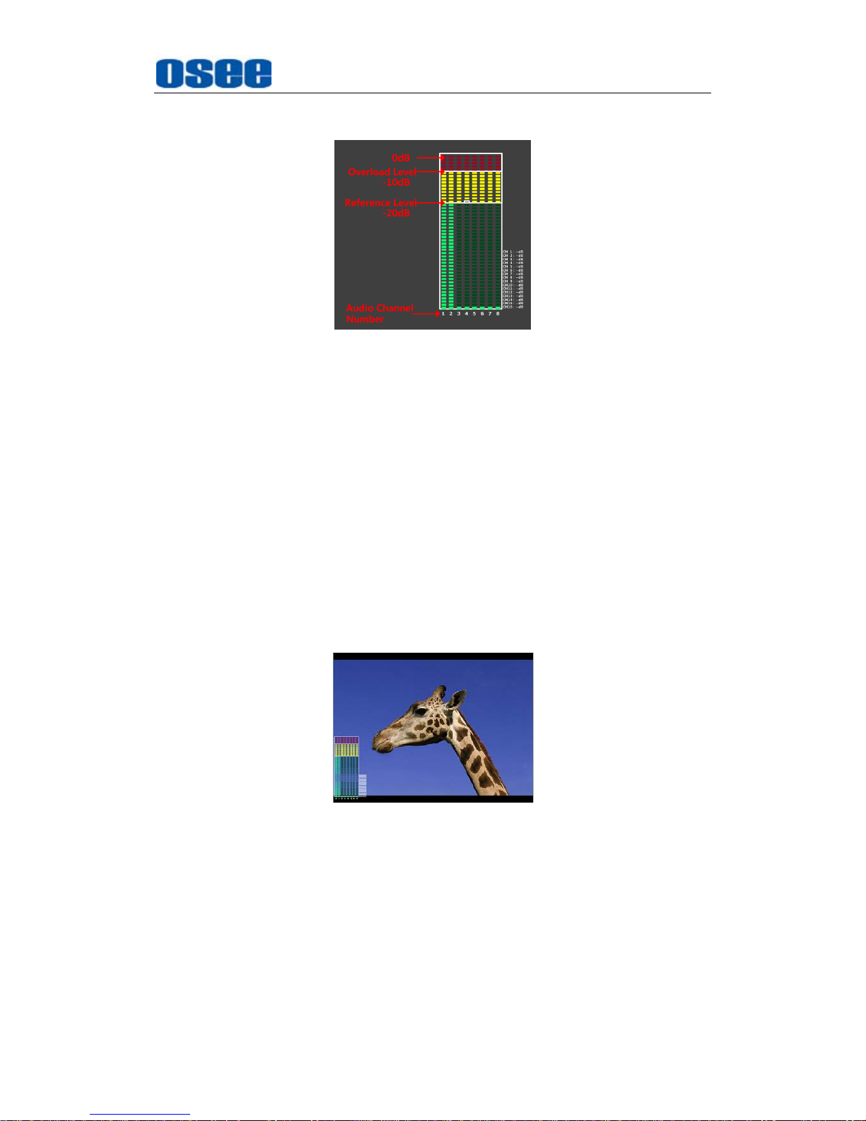
The appearance of Meter is as shown in Figure 5.1-13:
Figure 5.1-13 Audio Meter
METER SELECT
and
METER DIS MODE
control the operational
characteristics of Audio Metering, the former controls the amount of
channels displayed in a meter.
As shown in Figure 5.1-14, the meter displays at the left of the screen
vertically, the METER SELECT is G1+G2, and the METER DIS MODE
is MODE3, you can see the meter displays audio channel numbers and
audio values beside the meter. There is a white rectangle frame with two
white level lines in the meter, the upper is the over level line, and the
lower is the reference level line. If the audio value is higher than the
reference level, the audio bar over the reference level line will display
yellow, and if the audio value is higher than the over level, the audio bar
over the over level line will display red.
Figure 5.1-14 The Position of the Audio Meter On Screen
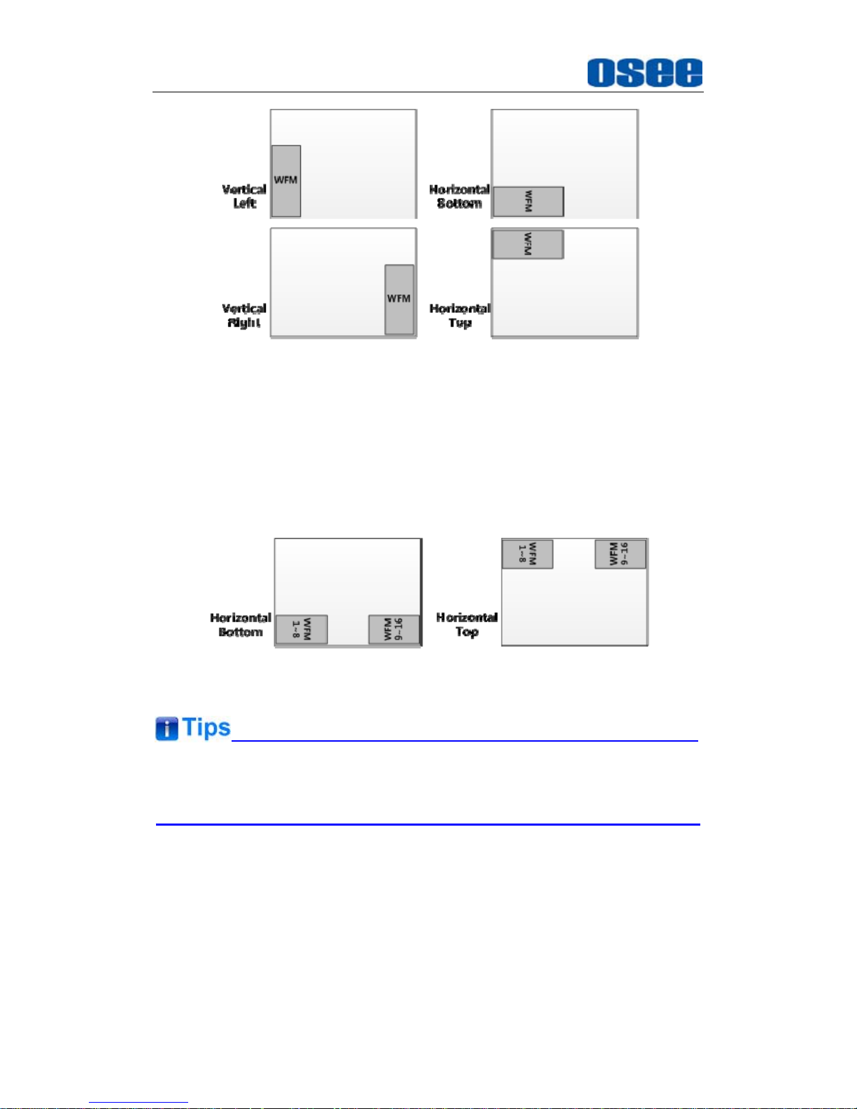
The position of Meter is controlled by
METER DIRECTION
and
METER POSITION
, the position of the meter on the screen is as
follows: BOT LEFT VERTICAL, BOT RIGHT VERTICAL, TOP LEFT
VERTICAL, TOP RIGHT VERTICAL, BOTTOM HORIZONTAL and
TOP HORIZONTAL. For example, the illustrations of some of the
positions are as shown in Figure 5.1-15:
Page 42
Functionality of the Main Menu
36
Figure 5.1-15 the Positions of Meter
Particularly, if the
METER SELECT
is
G1-4
, there will be 16 channels
displayed in audio meter, and if the
METER DIRECTION
is
Horizontal
,
the audio meter will display two meters separately on both sides of the
screen. One displays 8 channels(1~8) on the bottom or top left of the
screen, and the other displays 8 channels(9~10) on the bottom or top
right of the screen, the bottom or top is decided by
METER POSITION
,
as shown in Figure 5.1-16:
Figure 5.1-16 the Positions of the 16-channels Meter
The prerequisite for the available settings of the display mode and the
position of audio meter is that the
AUDIO METER
is ON.
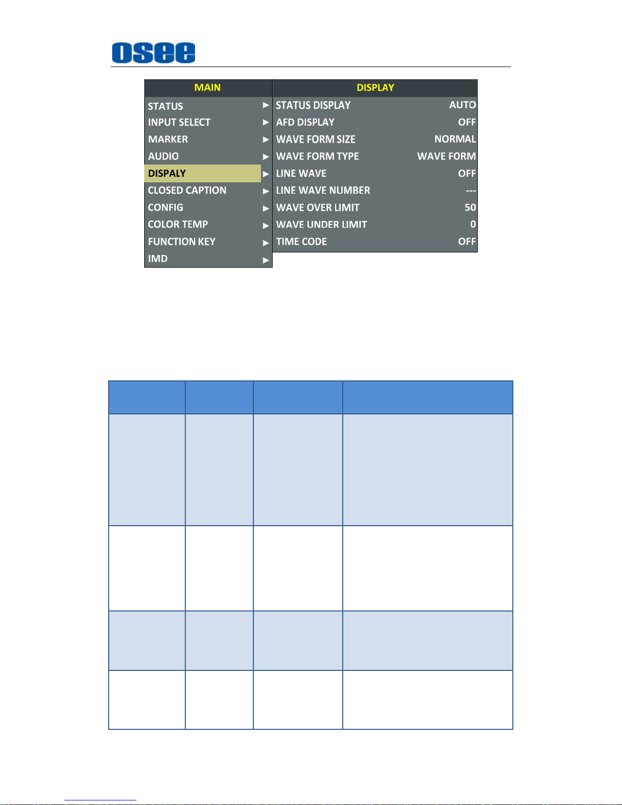
5.1.5 DISPLAY Menu
The DISPLAY menu items are used to adjust the parameters displayed on
the screen, the menu items are as shown in Figure 5.1-17:
Page 43
Functionality of the Main Menu
37
Figure 5.1-17 DISPLAY SETUP Menu
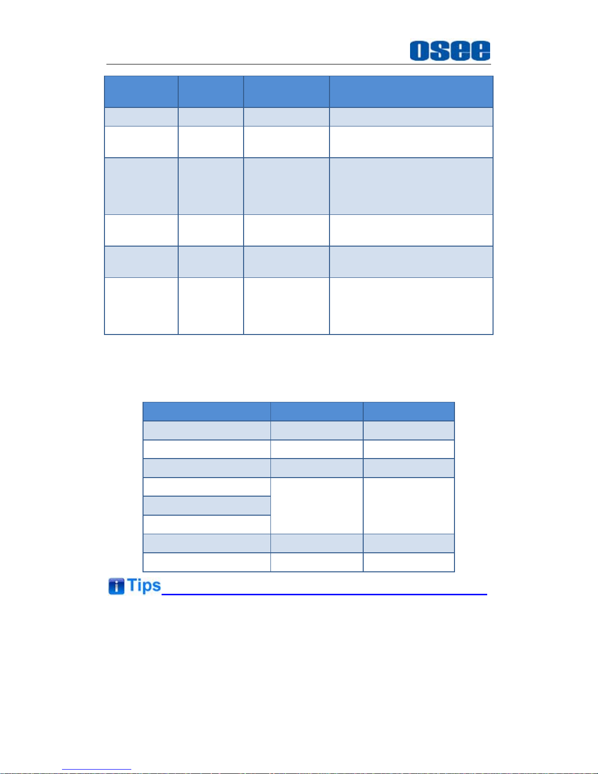
The relationship of Items, Default Value, Domain Range and Description
of the sub-item is shown in Table 5.1-5:
Table 5.1-5 The Description of DISPLAY SETUP Menu Items
Items
Default
Value
Domain Range Description
STATUS
DISPLAY
AUTO OFF/ON/AUTO
Set whether to display STD
information.
If the signal input is not equal to
"No signal" and this item is auto,
the status information will show
15 seconds when the status
changed, and then closed
automatically.
AFD
DISPLAY
OFF OFF/ON
Set whether to display AFD
information.
ON is an effective value to
AFD
DISPLAY
item only if the value
of
STATUS DISPLAY
is AUTO
or ON.
WFM FORM
SIZE
NORMAL
NORMAL:
Normal size
FULL: Full
screen
Set the display size of WFM/VT.
WFM FORM
TYPE
NORMAL
VECT100
VECT75
WAVE
FORM
Switch the display mode among
vector100, vector75 and wave
form.
Page 44
Functionality of the Main Menu
38
Items
Default
Value
Domain Range Description
LINE WAVE OFF OFF/ON Set whether to show line wave.
LINE WAVE
NUMBER
260
A
s shown in
Table 5.1-6.
Set the position of WFM.
WFM POS BOT RIGHT
BOT RIGHT
BOT LEFT
TOP LEFT
BOT RIGHT
Select the displayed position for
WFM.
WFM
OVERLIMIT
50 50~100 Set the over limit of WFM
WFM
UNDERLIMIT
0 0~50 Set the under limit of WFM
TIME CODE OFF
OFF
D-VITC
LTC
VITC
Set whether to display TC, and
select a mode for TC display.
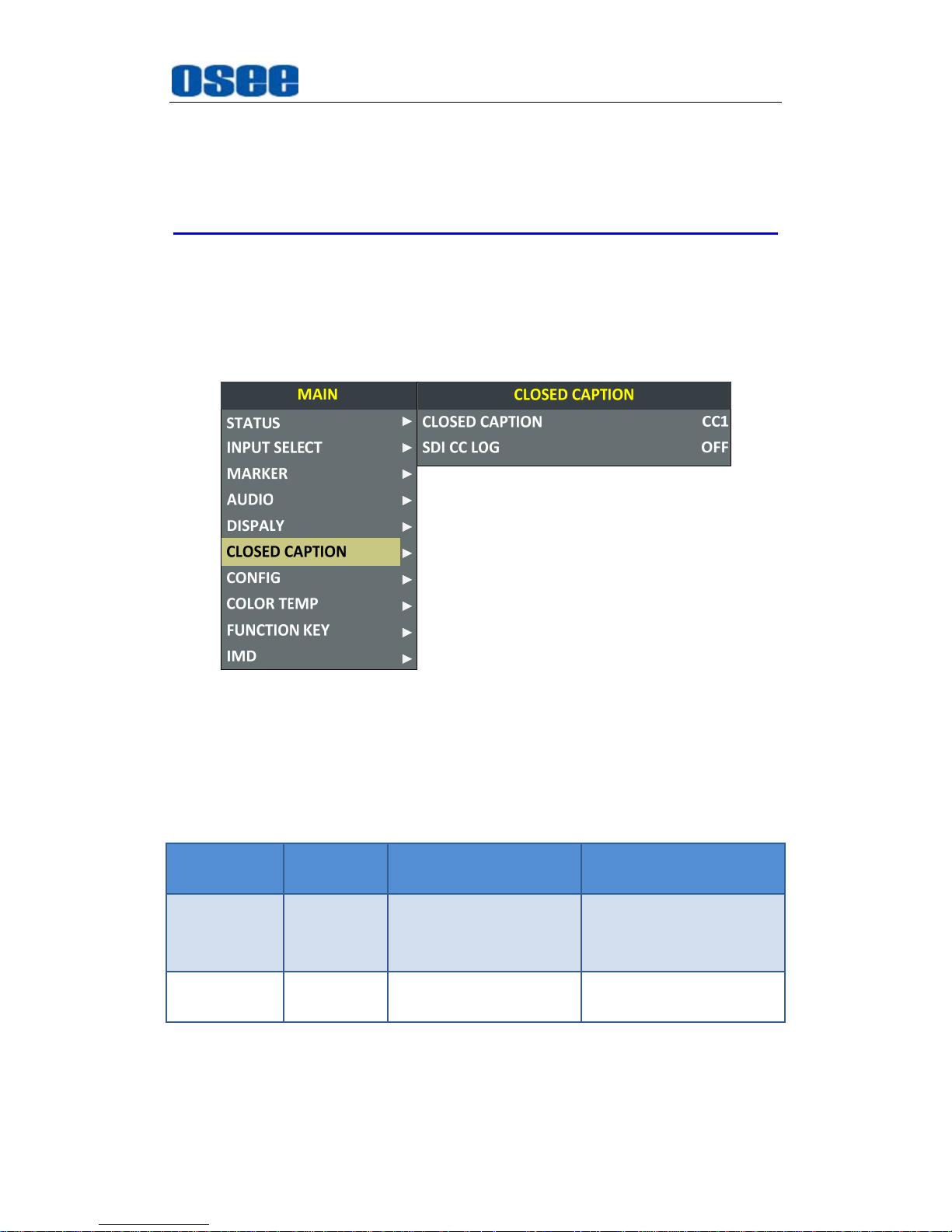
Thereinto, the value of LINE WFM is different according to the type of
input signal, as shown in Table 5.1-6.
Table 5.1-6 The Description for LINE WFM Item
Input Signal Default Domain Range
576i50 310 23~623
480i60 261 22~524
720p 386 26~745
1080i50
560 21~1123
1080i60/59.94
1080sf23/23.97
1035i60 557 41~1120
1080p 561 42~1121
The wave form could only be displayed in PIP mode or in PBP mode, You
can call out the wave form and configure its display mode through
DISPLAYWAVE FORM TYPE
, and configure its display position through
DISPLAY
WFM FORM SIZE
. The switch of PIP and PBP mode is
controlled by
CONFIG
SUB IN TYPE
command, refer to “5.1.7
Page 45
Functionality of the Main Menu
39
CONFIG Menu” for the details on PIP and PBP mode.
Please refer to the international standard SMPTE2016-1-2007 for the
details about AFD display.
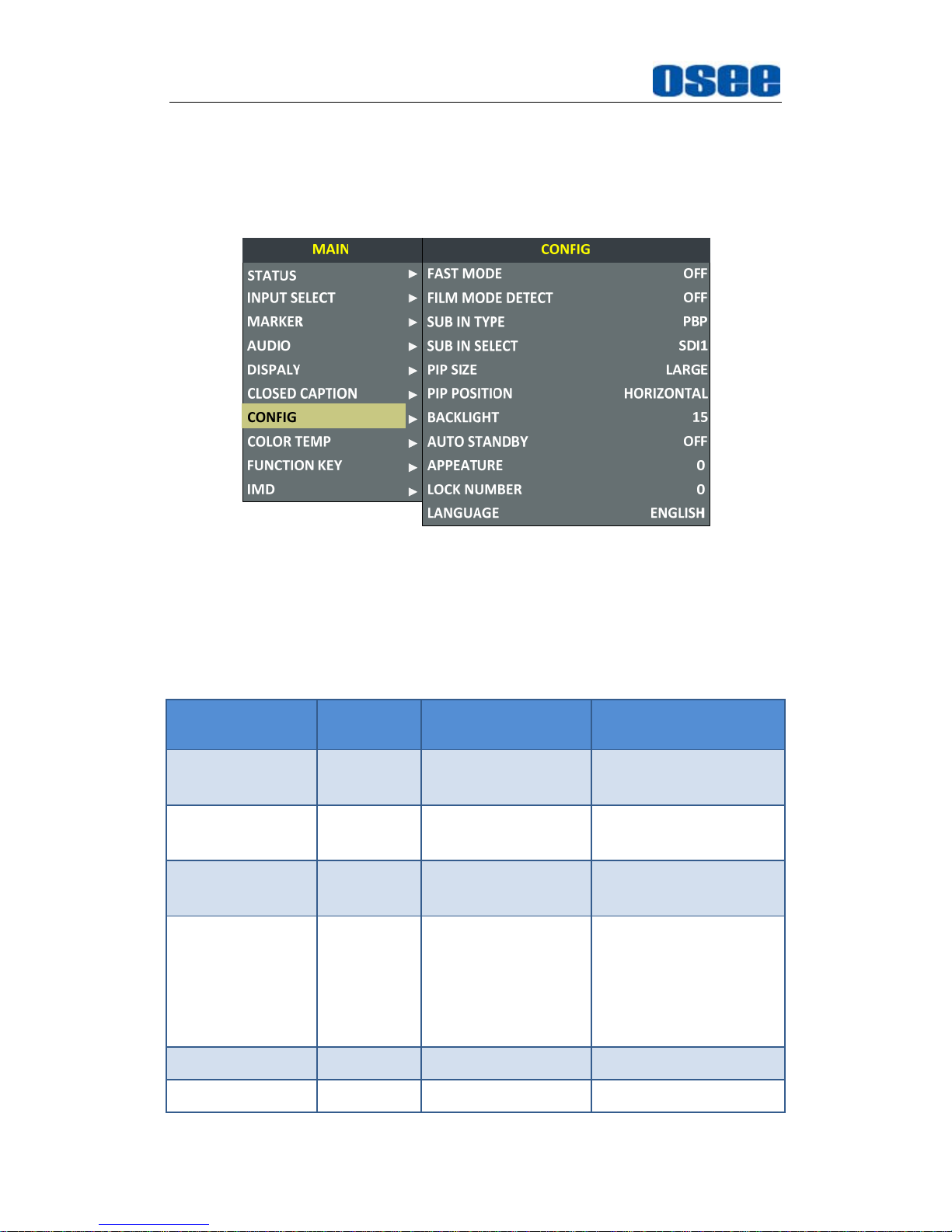
5.1.6 CLOSED CAPTION Menu
The CLOSED CAPTION menu items are used to adjust the parameters
displayed on the screen, the menu items are as shown in Figure 5.1-18:
Figure 5.1-18 CLOSED CAPTION Menu
The relationship of Items, Default Value, Domain Range and Description
of the sub-item is shown in Table 5.1-7:
Table 5.1-7 The Description of CLOSED CAPTION Menu Items
Items
Default
Value
Domain Range Description
CLOSE
CAPTION
OFF
CC1/CC2/CC3/CC4/
TEXT1/TEXT2/TEXT3/
TEXT4/OFF
Set whether to display
caption information, and
select its display mode.
SDI CC LOG OFF OFF/ON
Set whether to display
CC information.
Page 46
Functionality of the Main Menu
40
5.1.7 CONFIG Menu
The CONFIG menu items are used to adjust the parameters defined by
customers, the menu items are as shown in Figure 5.1-19:
Figure 5.1-19 CONFIG Menu
The relationship of Items, Default Value, Domain Range and Description
of the sub-item is shown in Table 5.1-8:
Table 5.1-8 The Description of CONFIG Menu Items
Items
Default
Value
Domain Range Description
FAST MODE OFF OFF/ON
Set whether in fast
mode.
FILM MODE
DETECT
OFF OFF/ON
Set whether to detect
film mode.
SUB IN TYPE PBP PBP/PIP/OFF
Set the arrangement
mode of screen picture
SUB IN SELECT SDI1
SDI1
SDI2
LINE1(CVBS)
LINE2(CVBS)
HDMI
WAVE FORM
Set the source of slave
picture, refer to Table
5.1-9 for the details.
PIP SIZE LARGE SMALL/LARGE Set the size of PIP
PIP POSITION BOT LEFT
BOT LEFT:
Set the position of PIP
Page 47
Functionality of the Main Menu
41
Items
Default
Value
Domain Range Description
bottom left
BOT RIGHT:
bottom right
TOP RIGHT
TOP LEFT
BACK LIGHT 15 0~30 Adjust the back light
AUTO STANDBY OFF OFF/ON
Set whether open the
standby mode.
APPERTURE 0 0~24
Set the picture
sharpness
LOCK NUMBER XXXXXXXX -- Set the lock number
LANGUAGE ENGLISH ENGLISH/CHINESE
Select a language
mode
1. Display Multiple Images
This monitor allows simultaneous display of two input signals on the
monitor’s screen. It will introduce the display mode, settings and signal
source selection for the multiple images on screen as follows.
(1) Display Mode
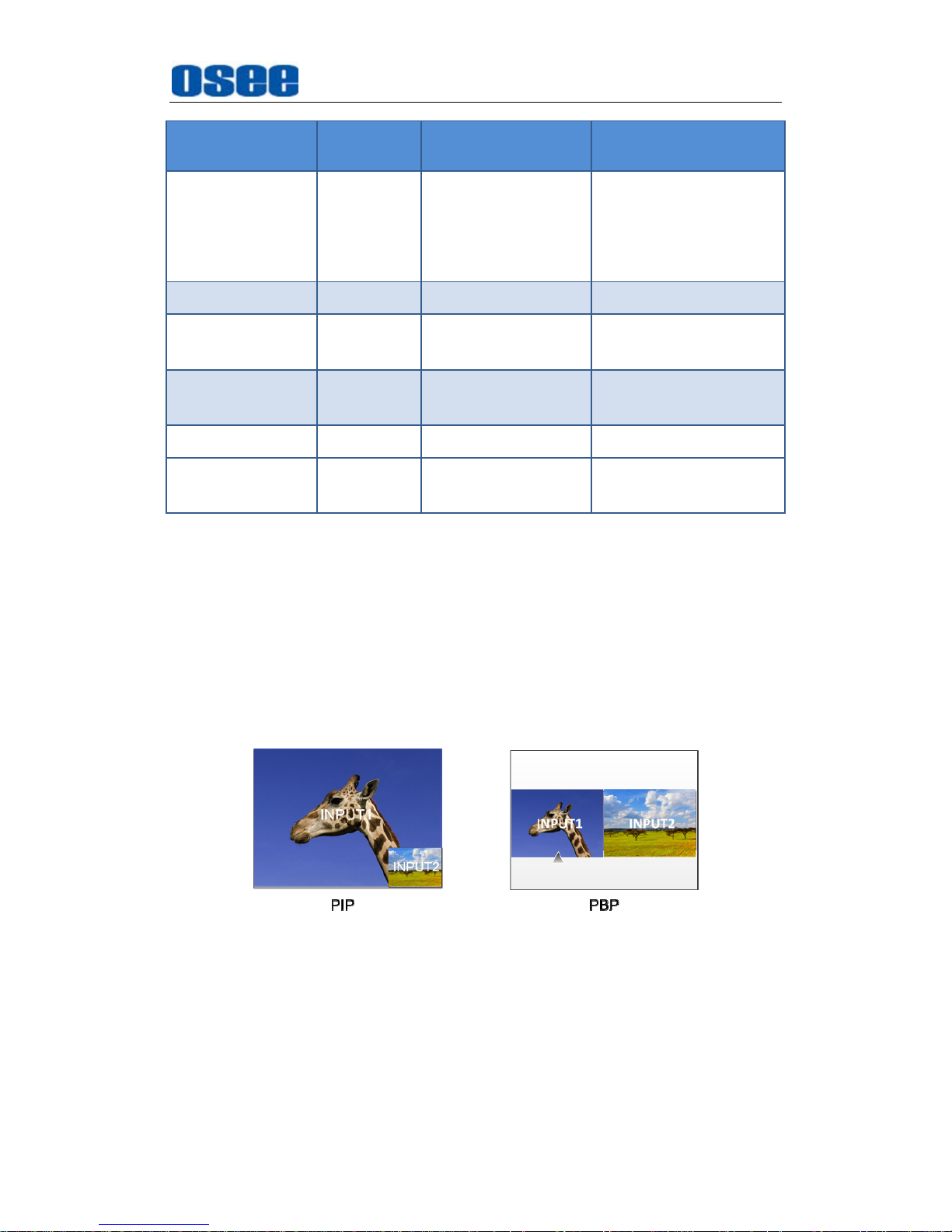
This device provides four modes for picture & picture display: PIP, PBP,
and the relevant relationship of the two pictures are as shown in Figure
5.1-20:
Figure 5.1-20 Multiple Inputs
PIP
(Picture in Picture)
The two pictures generated by two input signals separately are
displayed one in another. One is displayed on full screen, called as the
main picture, and the other is displayed in an inset window, called as the
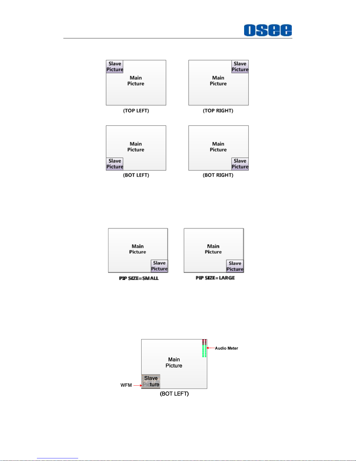
slave picture. In PIP mode, the relevant position relationship of the main
Page 48
Functionality of the Main Menu
42
picture and the slave picture is as shown in Figure 5.1-21:
Figure 5.1-21 The Position Relationship in PIP Mode
And you can adjust the display size by the PIP SIZE item, and there are
two kinds of outlines for the slave picture, as shown in Figure 5.1-22:
Figure 5.1-22 The Size for the Slave Picture
In PIP mode, if you set SUB IN SELECT to be WAVE FORM, it displays
the WFM in the position of the slave picture, and the content of the slave
picture is the WFM, as shown in Figure 5.1-23:
Figure 5.1-23 The Illustrate for WFM Display
Page 49
Functionality of the Main Menu
43
PBP
(Picture by Picture)
The two pictures generated by two input signals separately are
displayed side by side, and this function helps with white balance
adjustment, and determining shooting angles between two cameras etc.
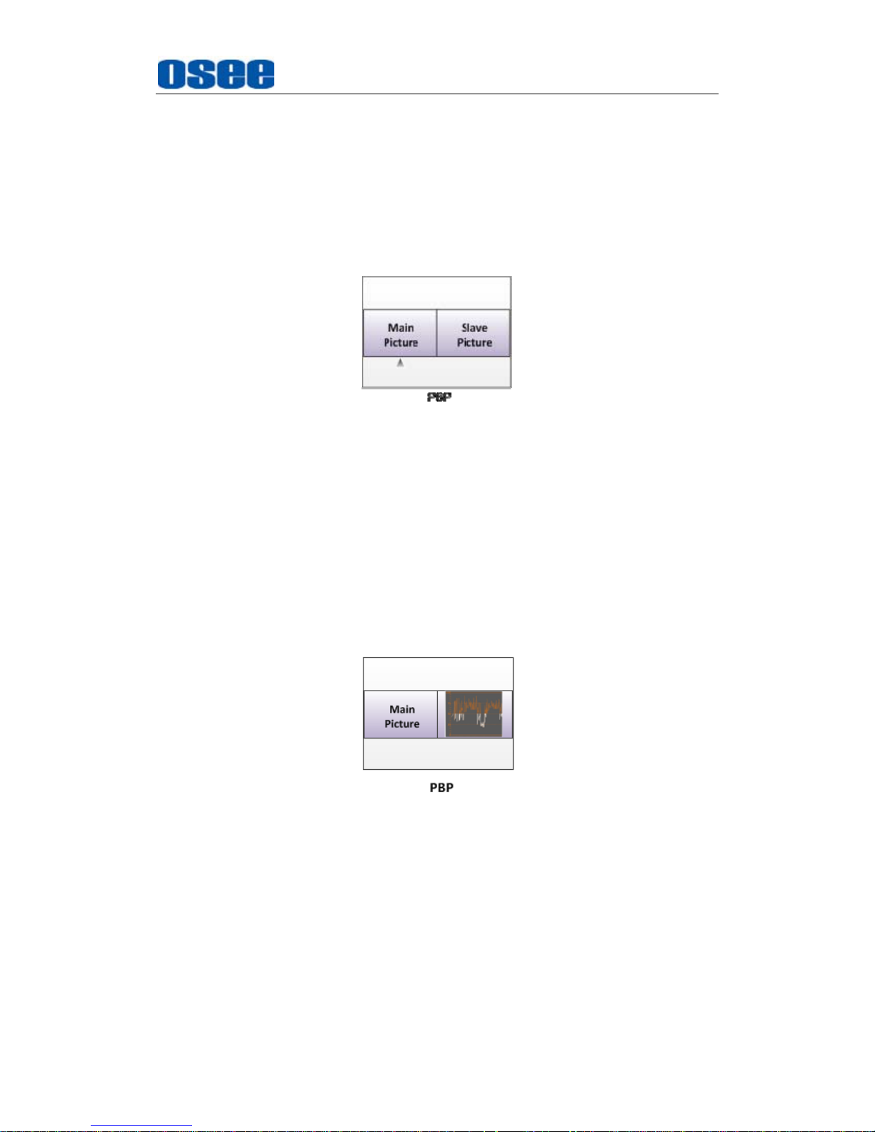
In PBP mode, the size of the main picture is as large as the slave
picture’s, and the position relationship of the main picture and the slave
picture is as shown Figure 5.1-24:
Figure 5.1-24 PBP Mode
In PBP mode, it displays the WFM or Audio Meter only for the signal of
the current picture. The current picture is labeled by a triangle, as
shown in Figure 5.1-24, at the bottom center of the picture. You can
select the current picture by the WIN SELECT command assigned to a
function key.
In PBP mode, if you set SUB IN SELECT to be WAVE FORM, it
displays the WFM in the position of the slave picture which is displayed
paralleled as the slave picture, as shown in Figure 5.1-25:
Figure 5.1-25 The Slave Picture Is Displayed as WFM
(2) Set Display Mode
The selection for picture & picture display mode contains the following
items: OFF, PBP, PIP, you can switch the selection as instructed below:
Method 1: By menu item.
Select the menu item Config SUB IN TYPE, use ENTER, UP or
DOWN key to select a display mode.
Page 50
Functionality of the Main Menu
44
Method 2: By function key.
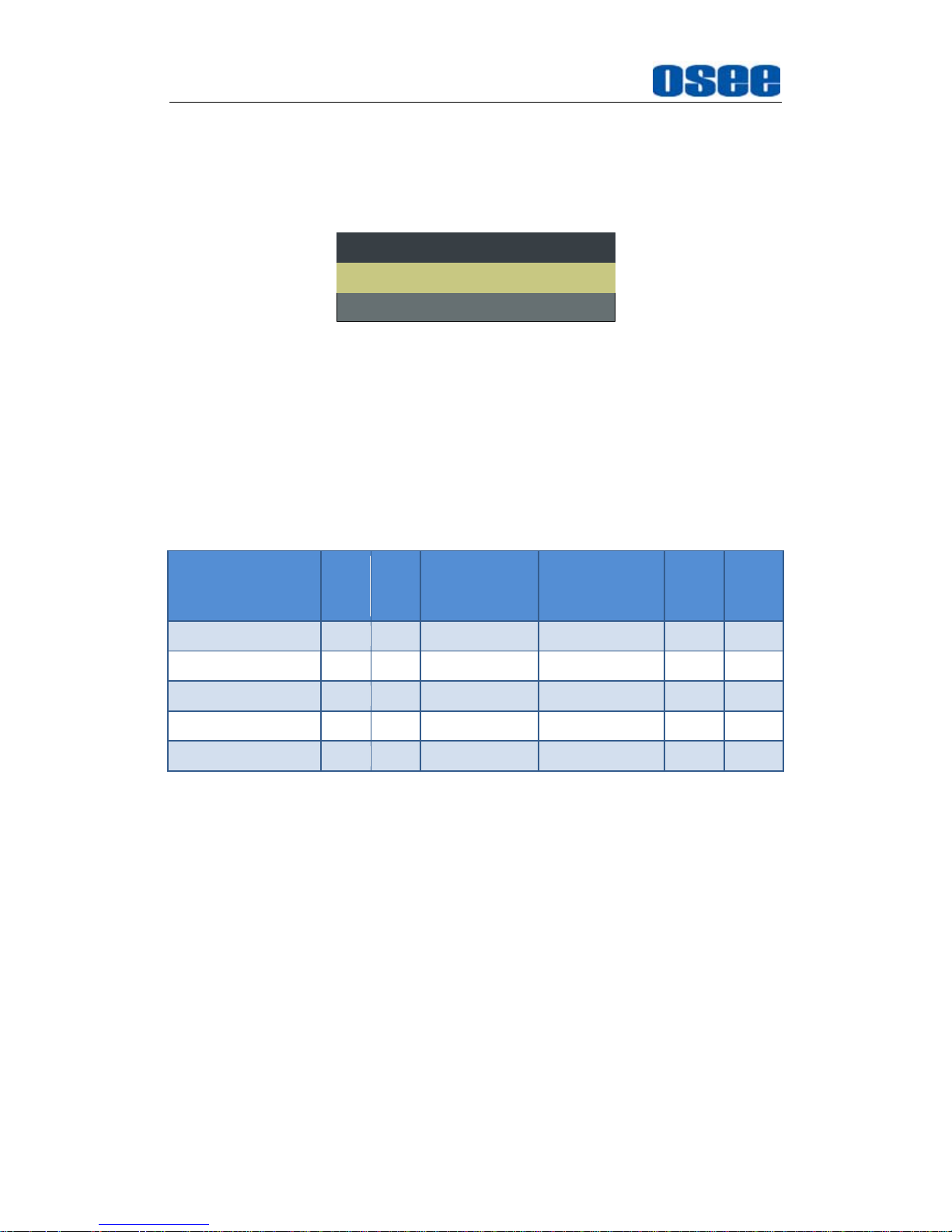
Set PBP function to a function key (F1~F5). Select the menu item
FUNCTION KEY F1 for example, and assign its sub-item value as
PBP, as shown in Figure 5.1-26:
F1 PBPPBP
F2 MAINWIN SELECT
FUNCTION
Figure 5.1-26 Set the Function Key as PBP
(3) Scope for the signal source of the slave picture
The selection scope of the signal source for the slave picture will be
changing with the main picture's source, as shown in Table 5.1-9:
Table 5.1-9 The Relationship of the Signal Source for Slave Picture and
Main Picture
Signal Source for Main
Picture
\ Signal Source for
Slave Picture
SDI1 SDI2 LINE1(CVBS) LINE2(CVBS) HDMI WFM
SDI1
SDI2
LINE1(CVBS)
LINE2(CVBS)
HDMI
Position for signal source
: The input signal information of the main
picture displays at the top left corner of the screen, and the one of the
slave picture displays at the top right corner of the screen.
Settings for signal source
: Press
INPUT
button to set the signal
source for the main picture, and select
CONFIGSUB IN TYPE
menu
item to set the signal source for the slave picture.
2. Auto Standby
The Auto Standby function is used to set the status of the monitor when
the Power button is turned on or off.
ON: AUTO STANDBY
is set to ON to enable the auto standby mode.
Thus, the auto standby will be activated when detecting no signal input
or signal disappeared, and there will be a prompt during the process,
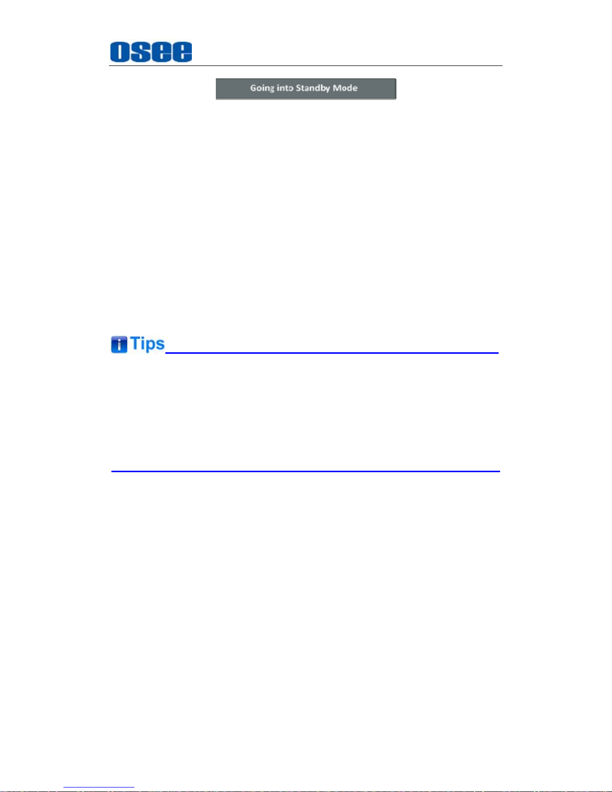
as shown in Figure 5.1-27:
Page 51
Functionality of the Main Menu
45
Figure 5.1-27 Entering the Auto Standby Mode
When detecting no signal input or signal disappeared, the power
indicator will be lit in flash green for 10 seconds, and showing the
standby prompt, after that, the monitor screen will be turned off, and it
will be in auto standby mode, the POWER indicator is lit in green. Then,
if the signal input is correct, the monitor screen will be lit up
automatically.
OFF: AUTO STANDBY
is set to
OFF
to disable the auto standby
mode.
Press POWER button when the monitor is in operation mode, it will
power off the monitor, otherwise, press POWER button when the
monitor is off, thus it will power on the monitor, and the POWER
indicator is lit in green.
The length of LOCK NUMBER is up to 8 characters, you can use the
combination of these characters: number (0 to 9) and letter (A to Z). Press
ENTER
to edit the LOCK NUMBER, than use UP or
DOWN
to select
characters, than press
ENTER
to go to next character, press
MENU
to exit
editor.
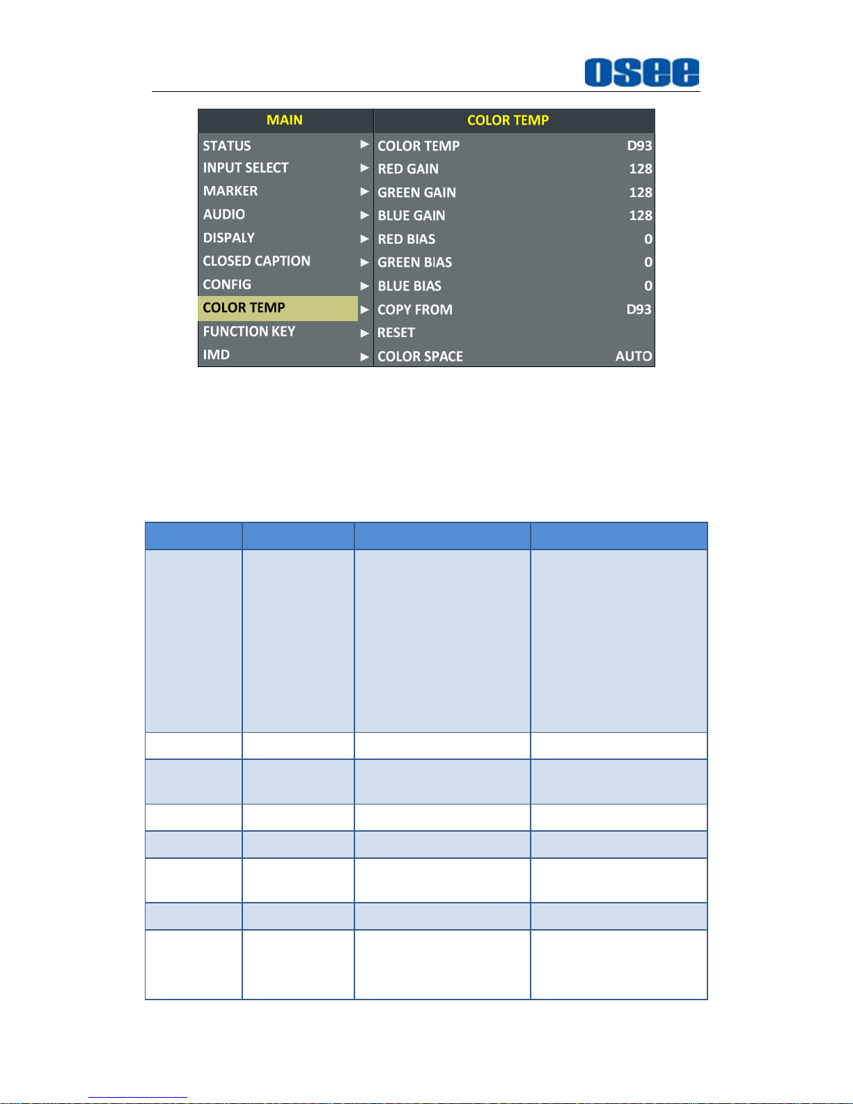
5.1.8 COLOR TEMP Menu
The COLOR TEMP menu items are used to adjust the color temperature
parameters and the color balance, the menu items are as shown in Figure
5.1-28:
Page 52
Functionality of the Main Menu
46
Figure 5.1-28 COLOR TEMP Menu
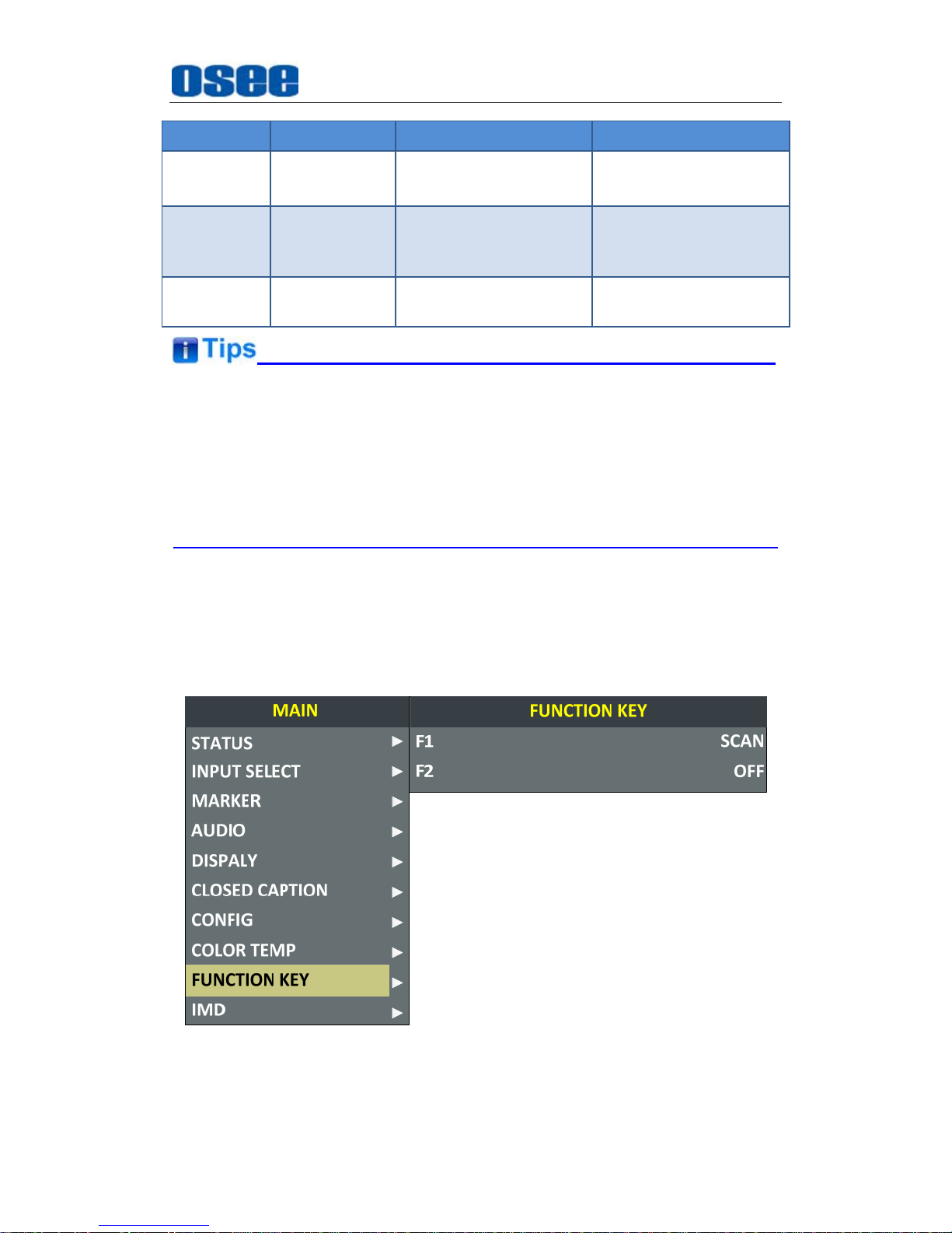
The relationship of Items, Default Value, Domain Range and Description
of the sub-item is shown in Table 5.1-10:
Table 5.1-10 The Description of COLOR TEMP Menu Items
Items Default Value Domain Range Description
COLOR
TEMP
D65
USER1:
Customized by user
USER2:
Customized by user
D32:3200K
D50:5000K
D56:5600K
D65:6500K
D93:9300K
Set color temperature
RED GAIN 128 0~256 Adjust the Red Gain
GREEN
GAIN
128 0~256 Adjust the Green Gain
BLUE GAIN 128 0~256 Adjust the Blue Gain
RED BIAS 0 -127~127 Adjust the Red Offset
GREEN
BIAS
0 -127~127 Adjust the Green Offset
BLUE BIAS 0 -127~127 Adjust the Blue Offset
COPY
FROM
D65
D32:3200K
D50:5000K
D56:5600K
Copy this parameter
value to USER
Page 53
Functionality of the Main Menu
47
Items Default Value Domain Range Description
D65:6500K
D93:9300K
RESET -- --
Reset the Gain and
Offset values to the
product originals
COLOR
SPACE
EBU
OFF/EBU/SMPTE-C/
ITU-709/AUTO
Select the color matrix
The items about RED/GREEN/BLUE GAIN and BIAS are available only in
USER1 and USER2 mode. If the COLOR TEMP is set to
USER1
or
USER2
with customized settings, you can select the menu item
COLOR TEMP
RESET
command to restore product originals for Gains and Offsets, and
press
ENTER
button to confirm the reset operation.
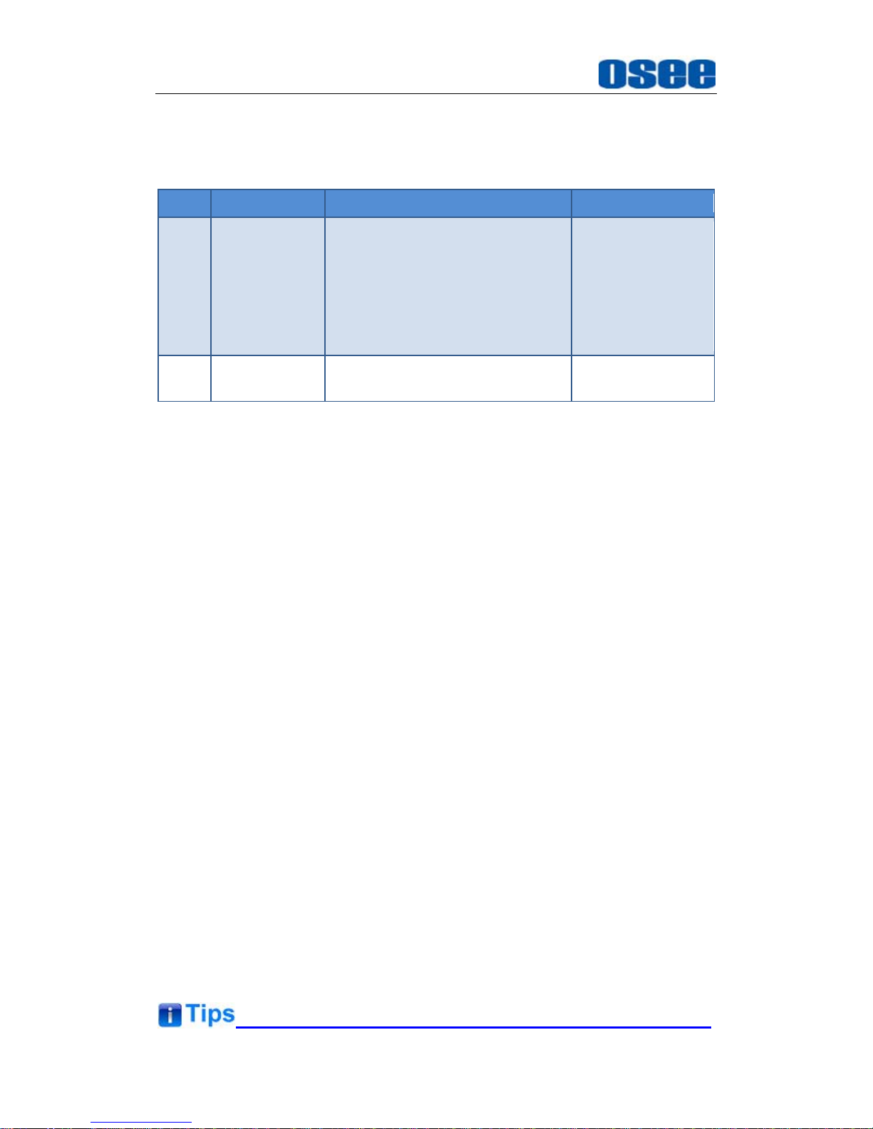
5.1.9 FUNCTION KEY Menu
The FUNCTION KEY menu items are used to define parameters to F1
and F2, the menu items are as shown in Figure 5.1-29:
Figure 5.1-29 FUNCTION KEY Menu
The relationship of Items, Default Value, Domain Range and Description
Page 54
Functionality of the Main Menu
48
of the sub-item is shown in Table 5.1-11:
Table 5.1-11 The Description of FUNCTION KEY Menu Items
Items Default Value Domain Range Description
F1 SCAN
SCAN, NATIVE, ASPECT, BLUE
ONLY, MONO, MARKER, H/V
DELAY, AUDIO METER, FAST
MODE, TC, IMD, MUTE, PBP,
CC, FREEZE, WIN SELECT,
FOCUS ASSIST, LUMA ZOOM
CHECK, UNDEF
Set a function to
F1 button
F2 SCAN the same as F1
Set a function to
F2 button
1. SCAN
This product supports the following scan modes:
NORMAL OVER UNDER
Set the function button as [SCAN], press the button continuously to
activate various scan modes.
OVER: Zooms in/out of the image to 96% of its original size
without changing the aspect ratio.
NORMAL: Zooms in/out of the image without changing the aspect
ratio.
UNDER: Zooms in/out of the image without changing the aspect
ratio. Also, displays the data at the top of the horizontal blanking
block.
2. ASPECT: Set the aspect ratio of the screen as 4:3 or 16:9.
3. FREEZE
Active this function to freeze the current frame displayed, press the
function button again to release the freeze and continue to display.
4. BLUE ONLY
It is to activate BLUE ONLY mode that will remove red and green from the
input signal and display the screen only under a blue signal.
5. MONO
It is to activate MONO mode that will display the screen in monochrome
presentation, inactivate this mode to display the screen in color mode.
Page 55
Functionality of the Main Menu
49
Press F1, F2 button to activate the assigned function and adjust the
parameter value.
The
SCAN
mode or the ASPECT mode is not selectable when Native mode
is set to ON.
Particularly, when the
PBP
function is assigned to a function key, press this
function key to select the display mode for picture & picture display.
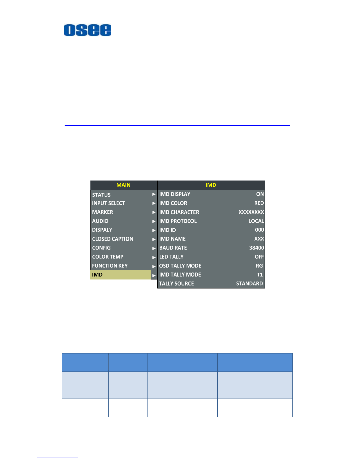
5.1.10 IMD Menu
The IMD menu items are used to adjust the parameters defined for IMD
display, the menu items are as shown in Figure 5.1-30:
Figure 5.1-30 IMD Menu
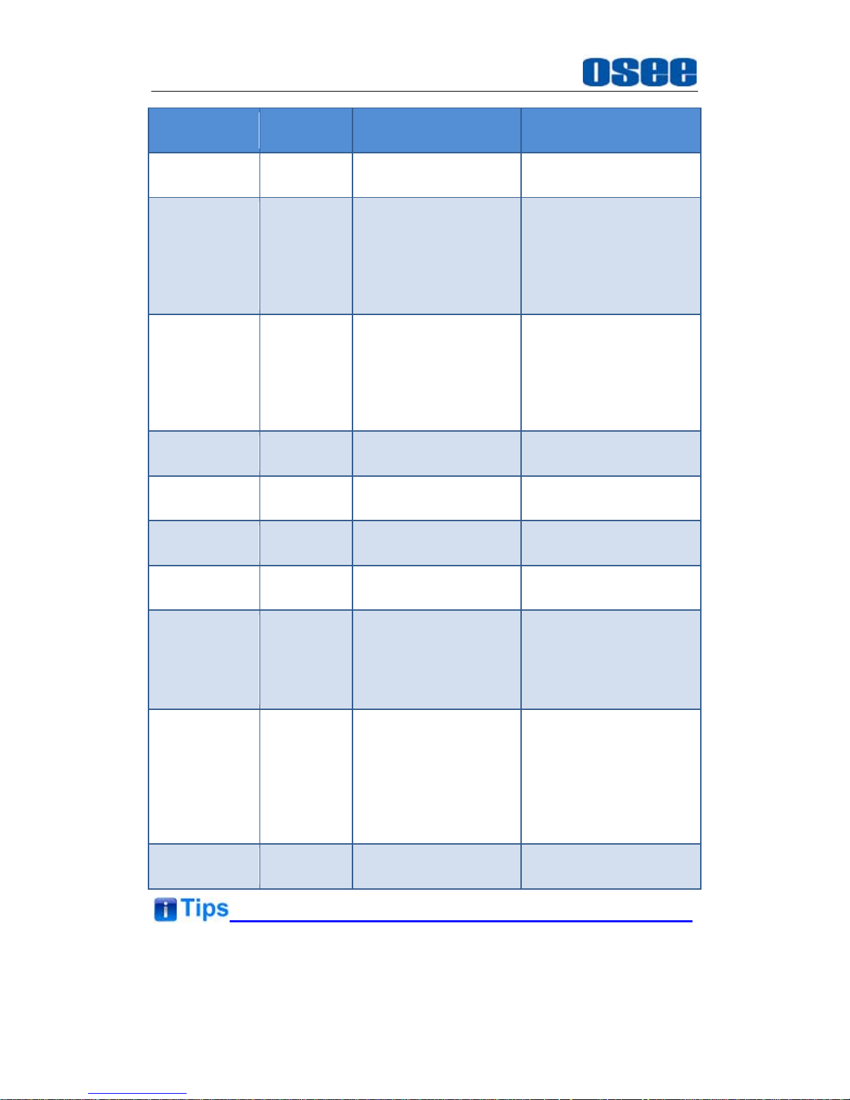
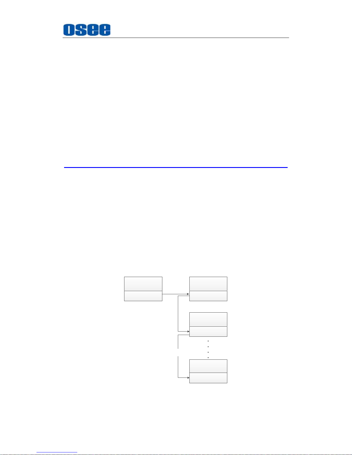
The relationship of Items, Default Value, Domain Range and Description
of the sub-item is shown in Table 5.1-12:
Table 5.1-12 The Description of IMD Menu Items
Items
Default
Value
Domain Range Description
IMD DISPLAY ON OFF/ON
Set whether to display
IMD CHARACTER on
screen.
IMD COLOR RED
RED
GREEN
Set the color for IMD
CHARACTER.
Page 56
Functionality of the Main Menu
50
Items
Default
Value
Domain Range Description
YELLOW
WHITE
IMD
CHARACTER
XXXXXXXX --
Set the IMD string
displayed on the screen.
A
fter entering this item,
press Up or Down to
choose your character
for this IMD string.
IMD
PROTOCAL
LOCAL
LOCAL
TSL3.1
TSL4.0
TSL5.0
IMAGE VIDEO
NETWORK
Select an IMD protocol
IMD ID 000 0~255
Set the ID number for
IMD
IMD NAME XXXXXXXX
Set an IMD name for
each screen.
BAUD RATE 38400
2400/4800/9600/19200
/38400/57600/115200
Select a baud rate for
communication.
LED TALLY ON OFF/ON
Set whether to switch on
tally light.
OSD TALLY
MODE
RG
RG: Red/Green
GR: Green only
RGY:
Red/Green/Yellow
OFF: No tally light
Select the OSD Tally
mode. Only the TALLY
SOURCE is
STANDARD, the setting
is available.
IMD TALLY
MODE
T1
T1/T2/T1T2/T2T1/T1-/
T2-/T1T2-/T2T1-
Select the IMD Tally
mode. Use this setting
when using the Image
Video tally control, this
item will determine the
IMD state as the
selected value.
TALLY
SOURCE
STANDARD
STANDARD/IMAGE
IDEO/TSL
Select the source for
OSD Tally source
The length of IMD NAME and IMD CHARACTER is up to 16 characters.
The character range is from 0x00 to 0x7F of ASCII. Press
ENTER
to edit
Page 57
Functionality of the Main Menu
51
the IMD characters, than use
∧
(Up)
and
∨
(Down)
to select characters,
than press
ENTER
to go to next character, press
MENU
to exit editor.
When the IMD PROTOCAL is set to be
Local
, the IMD CHARACTER can
only be modified through the control buttons(
∧
(Up)
and
∨
(Down)
), and
the IMD CHARACTER could be composed of up to 16 characters. When
the IMD PROTOCAL is set to be NETWORK, the IMD CHARACTER
should be modified through the IMD page in the network control page, and
the IMD CHARACTER could be composed of up to 16 characters or up to
12 Chinese characters. For other values of IMD PROTOCAL, the IMD
CHARACTER abides by the corresponding protocol.
The PRM1014 monitor could receive the Tally control signal from a TSL server,
and display the Tally information on PRM1014 through the LED tally and OSD
tally. We support the TSI3000 and TSL TallyMan Controller as the TSL server,
and it will be introduce how to connect with them, and how to set the IMD
parameters for various IMD protocol.
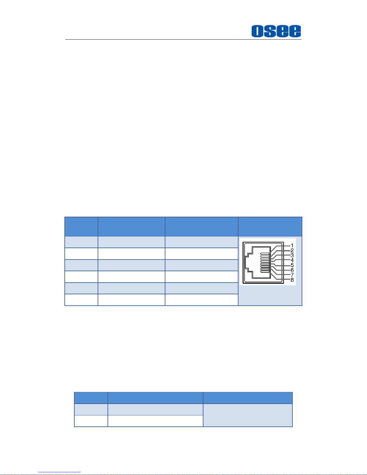
5.1.10.1 Device Connection
Follow the instructions below to connect monitor with TSL server.
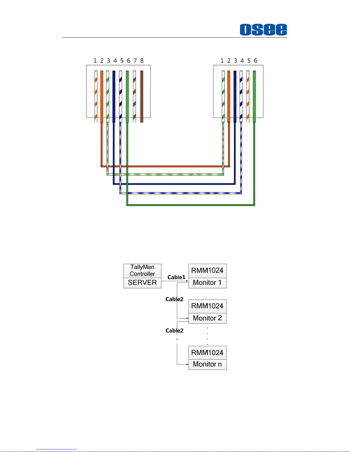
1. TSI-3000--RMM1024
Connect the TSI-3000 with RMM1024, as shown in
Figure 5.1-31
:
RMM1024
Monitor 1
RMM1024
Monitor 2
TSI-3000
SERVER
Cable1
Cable2
\\
RMM1024
Monitor n
Cable2
Figure 5.1-31 TSL Server and Display Monitor
Page 58
Functionality of the Main Menu
52
We recommend the following two methods according to the different interface
of TSI-3000 which is selected to connect with RMM1024.
METHOD1
Use the COM7~COM12 interface of TSI-3000 to connect
with RMM1024
Cable1
Use Cable1 to connect one of the COM7~COM12 interface at the rear
panel of TSI-3000 with the RS485 Interface of RMM1024, the functionality
of the interfaces are as shown in the following table.
RS485(RMM1024): RJ45
Use the RS485 interface to connect with TSI-3000, the RS485 uses the
RJ45 connector, and the function of RS485 interface of RMM1024 is
defined as in Table 5.1-13:
Table 5.1-13 The Pins Input/output connectors for RS485 of RMM1024
PIN No.
RS485 IN Terminal
Signal
RS485 OUT Terminal
Signal
Illustration
1,2 GND GND
3 Tx- Tx-
4 Rx+ Rx+
5 Rx- Rx-
6 Tx+ Tx+
7,8 NC NC
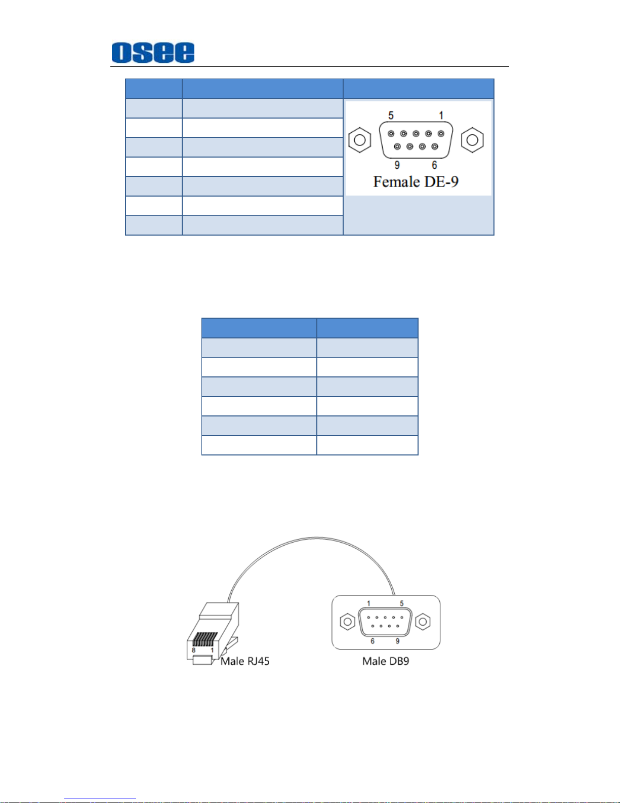
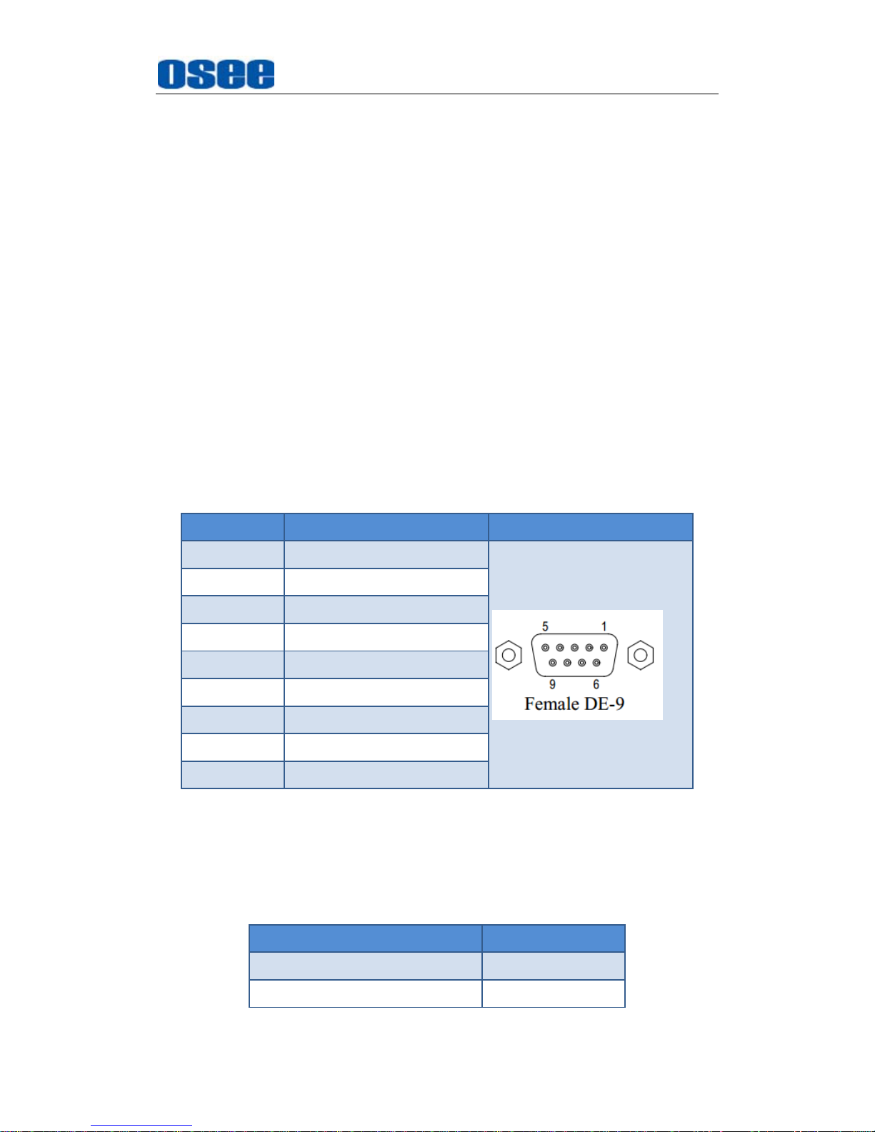
COM(TSI-3000): DB9
Use one of the COM7~COM12 interface at the rear panel of TSI-3000
to connect with RMM1024 monitor, the COM7~COM12 has the female
DB9 connector, and the function of COM7~COM12 interface of
TSI-3000 is defined as in Table 5.1-14:
Table 5.1-14 The Pins of COM* in TSI-3000
PIN No. DB9 Illustration
1 GND
2 Rx-(data from external device)
Page 59
Functionality of the Main Menu
53
PIN No. DB9 Illustration
3 Tx+(data to external device)
4 GND(Tx Data Common)
5 NC
6 GND(Rx Data Common)
7 Rx+(data from external device)
8 Tx-(data to external device)
9 GND
The connection should obey the rules below to set up the communication
between one of
COM7~COM12
and RS485, as shown in
Table 5.1-15
:
Table 5.1-15 Connection Between COM7~COM12 of TSI-3000 and RS485
of RMM1024
DB9(COM7~COM12) RJ45(RS485)
2 3
3 4
4 2
6 1
7 6
8 5
Cable1
The connectors at the two ends of CABLE1 should be one male RJ45
connector and one Male DB9 connector, as shown in Figure 5.1-32:
Figure 5.1-32 Cable1
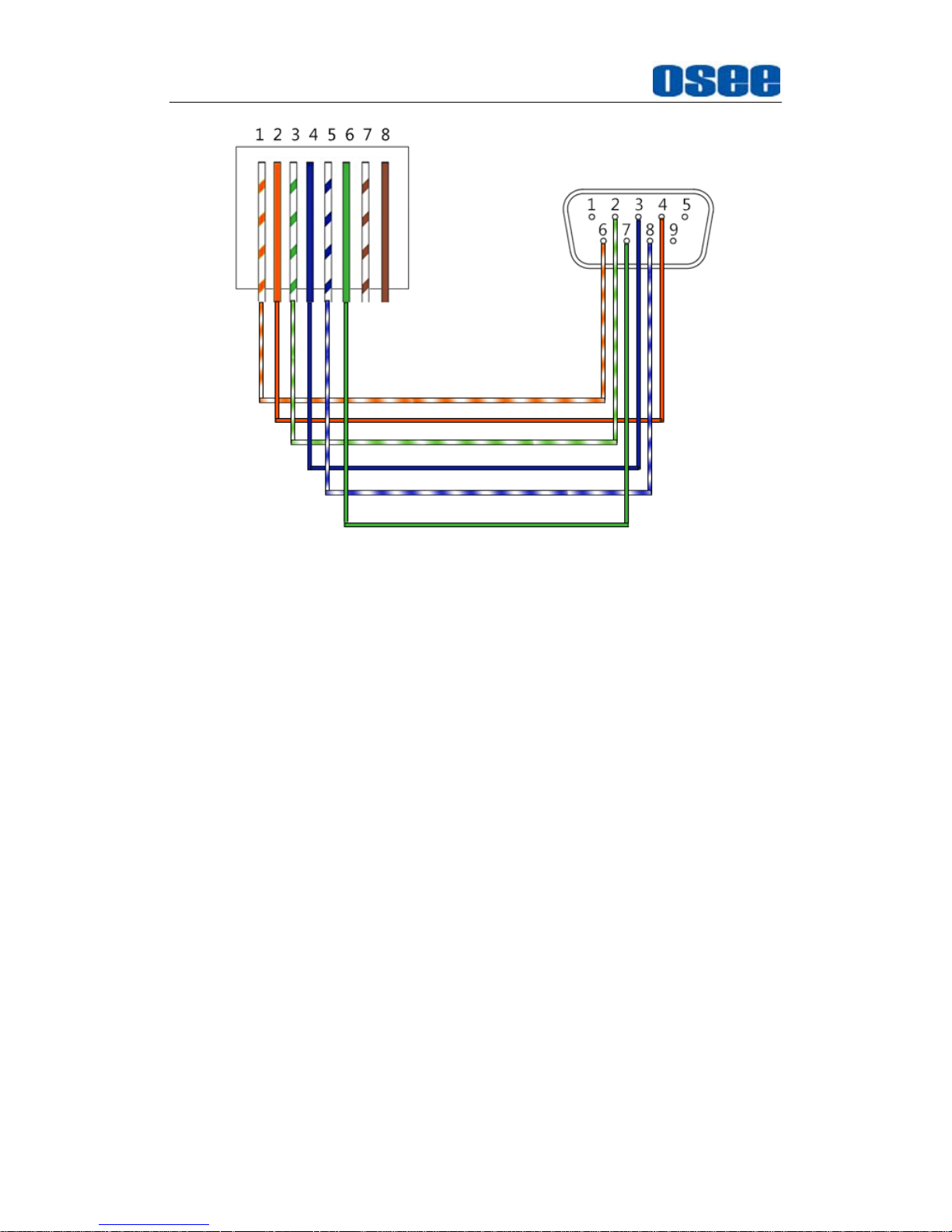
The pin sequence should be defined as in Figure 5.1-33:
Page 60
Functionality of the Main Menu
54
Figure 5.1-33 Pin Sequence of Cable1
METHOD2
Use the COM3~COM6 interface of TSI-3000 to connect with
RMM1024
Cable1
Use Cable1 to connect one of the COM3~COM6 interface at the rear
panel of TSI-3000 with the RS485 Interface of RMM1024, the functionality
of the interfaces are as shown in the following table.
RS485(RMM1024): RJ45
Use the RS485 interface to connect with TSI-3000, the RS485 uses the
RJ45 connector, and the function of RS485 interface of RMM1024 is
defined as in Table 5.1-13, please refer to the above Table 5.1-13 for
the details, no repeat here.
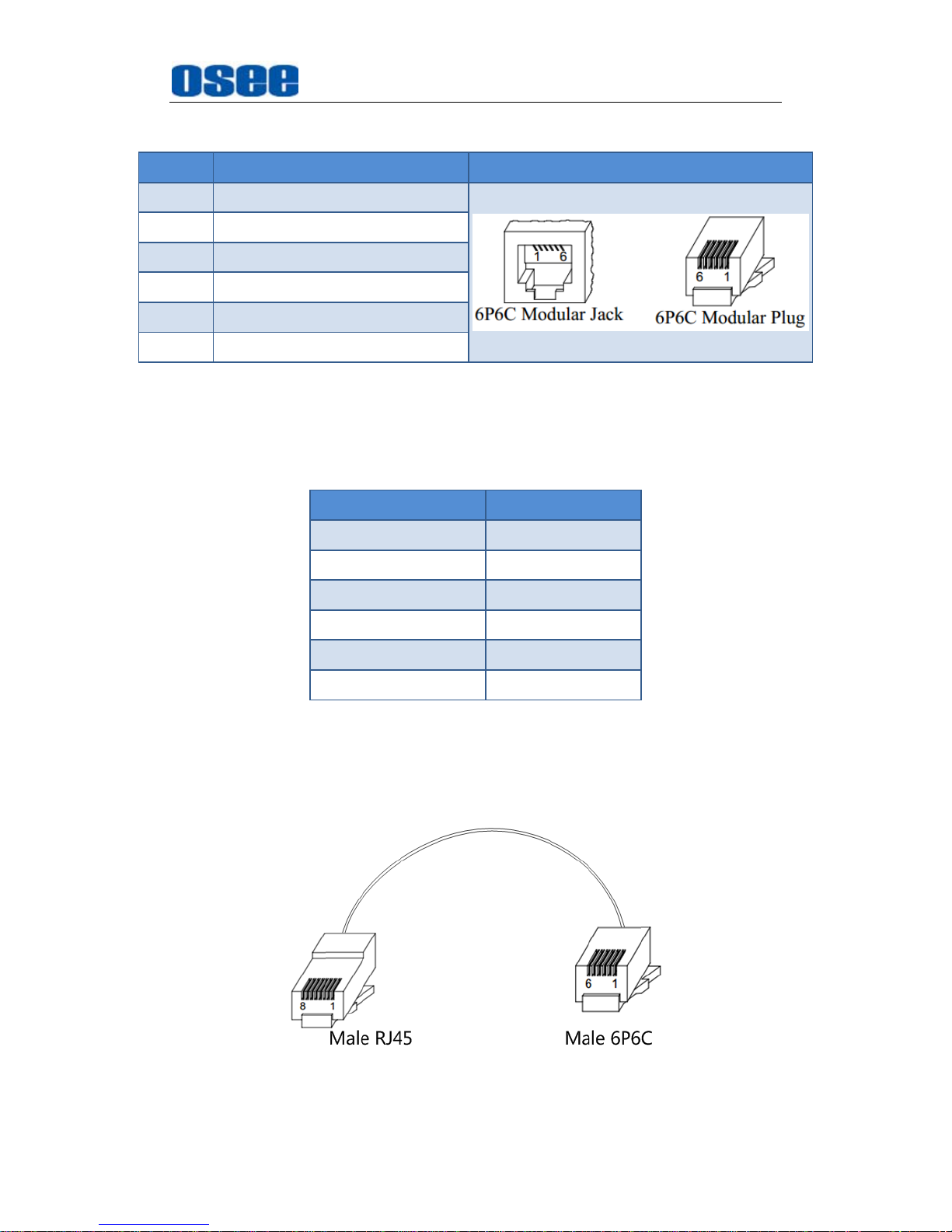
COM(TSI-3000): 6P6C
Use one of the COM3~COM6 interface at the rear panel of TSI-3000 to
connect with RMM1024 monitor, the COM3~COM6 has the 6P6C
connector, and the function of COM3~COM6 interface of TSI-3000 is
defined as in Table 5.1-16:
Page 61
Functionality of the Main Menu
55
Table 5.1-16 The Pins of COM* in TSI-3000
PIN No. 6P6C Illustration
1 Rx-(data from external device)
2 GND(Data Common)
3 Tx+(data to external device)
4 Tx-(data to external device)
5 Not connected
6 Rx+(data from external device)
The connection should obey the rules below to set up the communication
between one of
COM3~COM6
and RS485, as shown in
Table 5.1-17
:
Table 5.1-17 Connection Between COM3~COM6 of TSI-3000 and RS485
of RMM1024
6P6C(COM3~COM6) RJ45(RS485)
1 3
3 4
2 2
5 (Not connected) 1(Not connected)
6 6
4 5
Cable1
The connectors at the two ends of CABLE1 should be one male RJ45
connector and one Male 6P6C connector, as shown in Figure 5.1-34:
Figure 5.1-34 Cable1
Page 62
Functionality of the Main Menu
56
The pin sequence should be defined as in Figure 5.1-35:
Figure 5.1-35 Pin Sequence of Cable1
2. TallyMan--RMM1024
Connect the TallyMan Controller TM1/TM2/TM2 PLUS with RMM1024, as
shown in
Figure 5.1-36
:
Figure 5.1-36 TSL Server and Display Monitor
Cable1
Page 63
Functionality of the Main Menu
57
Use Cable1 to connect one of the CONTROL1/CONTROL2(RS422)
interface at the rear panel of TallyMan Controller with the RS485 Interface
of RMM1024, the functionality of the interfaces are as shown in the
following table.
RS485(RMM1024): RJ45
The definition of RS485 interface of RMM1024 is as the same as in
TSI-3000-RMM1024 system, please refer to the above Table 5.1-13 for
the details, no repeat here.
RS422(TallyMan Controller): DB9
Use one of the CONTROL1/CONTROL2 interface at the rear panel of
TallyMan Controller to connect with RMM1024 monitor, the
CONTROL1/CONTROL2 is a RS422 interface using female DB9
connector, and the pins of DB9 is defined as in Table 5.1-18:
Table 5.1-18 The Pins of CONTROL1/CONTROL2 in TallyMan Controller
PIN No. DB9 Illustration
1 0v/Chassis
2 Tx-
3 Rx+
4 0v
5 -
6 0v
7 Tx+
8 Rx-
9 0v
The connection should obey the rules below to set up the communication
between one of
CONTROL1/CONTROL2
and RS485, as shown in
Table
5.1-19
:
Table 5.1-19 Connection Between CONTROL1/CONTROL2 of TallyMan
Controller and RS485 of RMM1024
DB9(CONTROL1/CONTROL2) RJ45(RS485)
2 5
3 6
Page 64
Functionality of the Main Menu
58
DB9(CONTROL1/CONTROL2) RJ45(RS485)
4 2
6 1
7 4
8 3
TSL TallyMan Controller TM1, TSL TallyMan Controller TM2, TSL TallyMan
Controller TM2 PLUS all comfort to the above definition about the
connection and the pins relationship. Refer to the user manuals of these
devices for details.
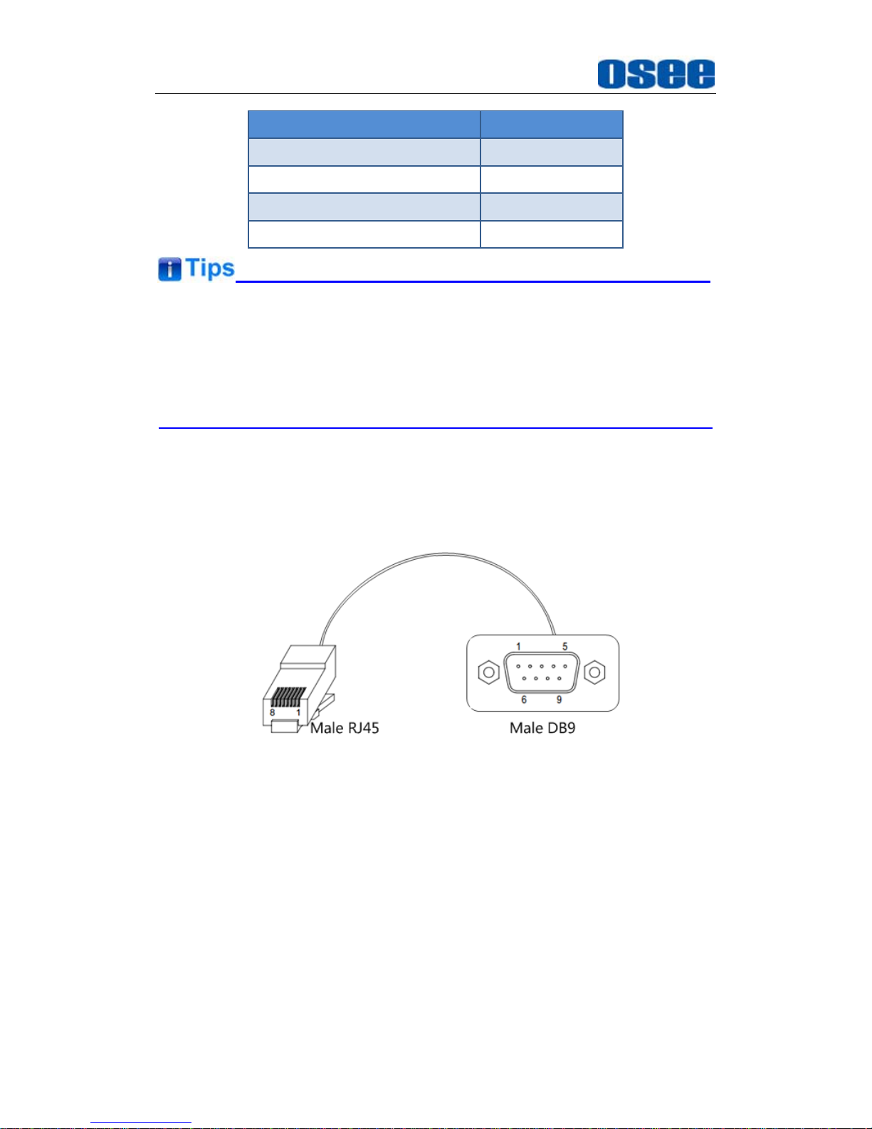
Cable1
The connectors at the two ends of CABLE1 should be one male RJ45
connector and one Male DB9 connector, as shown in Figure 5.1-37:
Figure 5.1-37 Cable1
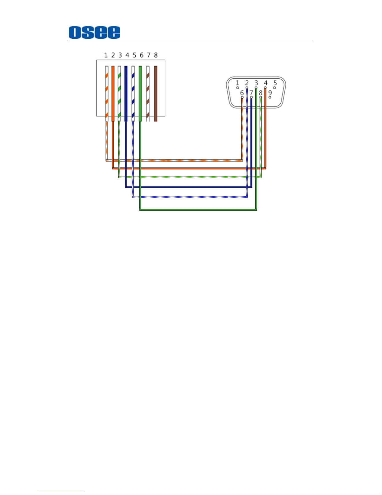
The pin sequence should be defined as in Figure 5.1-38:
Page 65
Functionality of the Main Menu
59
Figure 5.1-38 Pin Sequence of Cable1
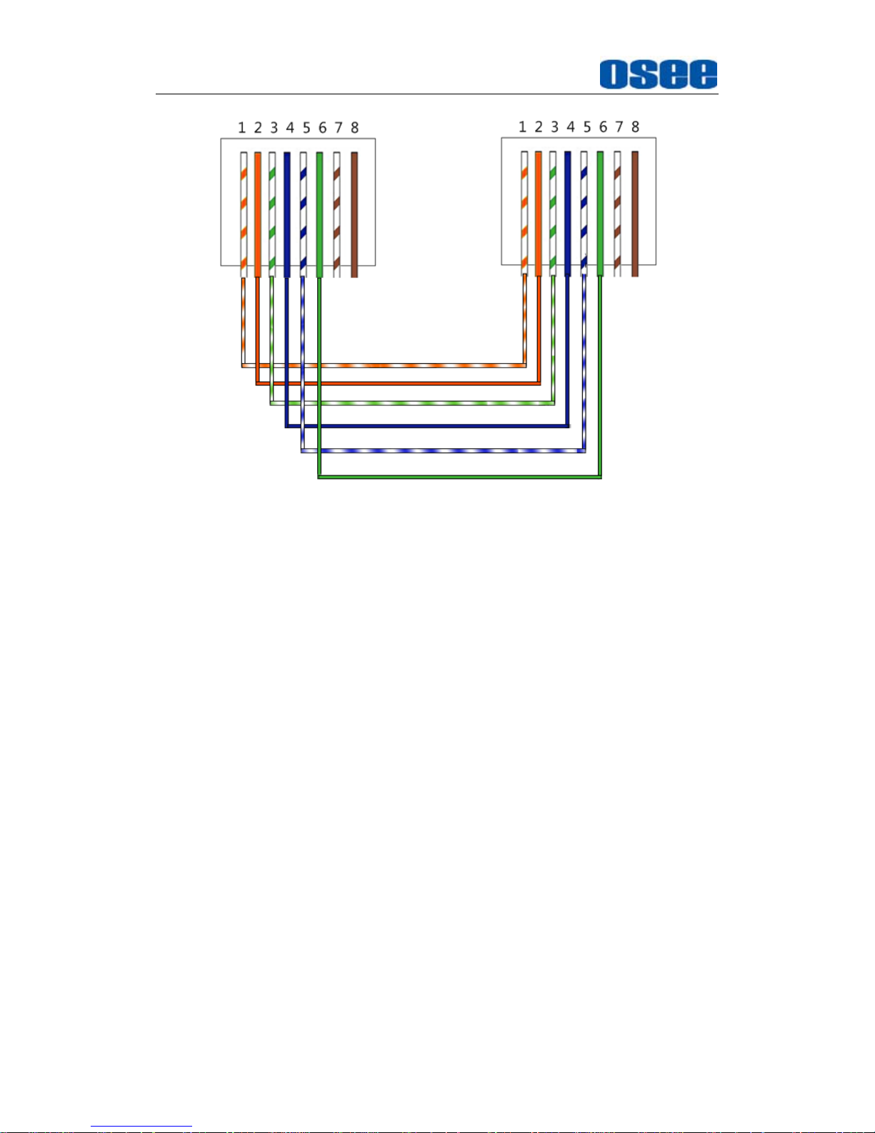
Cable2
Use
Cable2
to connect every two RMM1024 monitors through the RS485
Interface, the
Cable2
is a straight through line, and the connectors at the
two ends of
Cable2
should both be male RJ45. The pin sequence of
Cable2
should be defined as in
Figure 5.1-39
:
Page 66
Functionality of the Main Menu
60
Figure 5.1-39 Pin Sequence of Cable2
5.1.10.2 IMD Settings
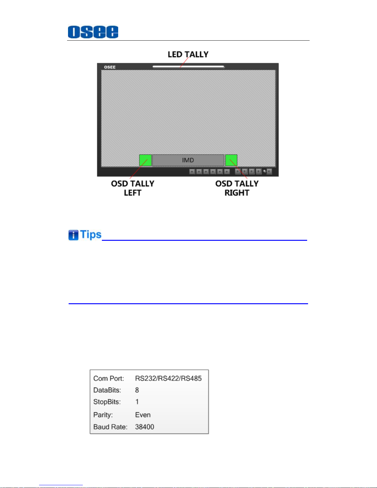
The position of Tally display on the PRM1014 monitor is as shown in
Figure 5.1-40
. The
LED Tally
indicator is displayed at the top center of
the monitor, and the two
OSD Tally
lights are displayed at the bottom of
the monitor screen, separately at the left and right side of the IMD
characters.
The tally lights will be in various color when selecting different values for
the
IMD Protocol
item. It will introduce one by one in the below.
Page 67
Functionality of the Main Menu
61
Figure 5.1-40 Tally Display
When receiving data of TSL3.1 or TSL4.0 protocol, we support the data
length to be 0~126 and 128~254. When the data is in 128~254, the result
will be equal to subtract 128 from the IMD ID, in addition, the data length is
0~255 when receiving data of MAGE VIDEO protocol.
1. TSL3.1
Set
IMDIMD Protocol
item to be TSL3.1, the monitor could receive the
tally control command from a TSL Tally controller or other control devices
conforming to TSL3.1 protocol.
Physical characteristic
Page 68
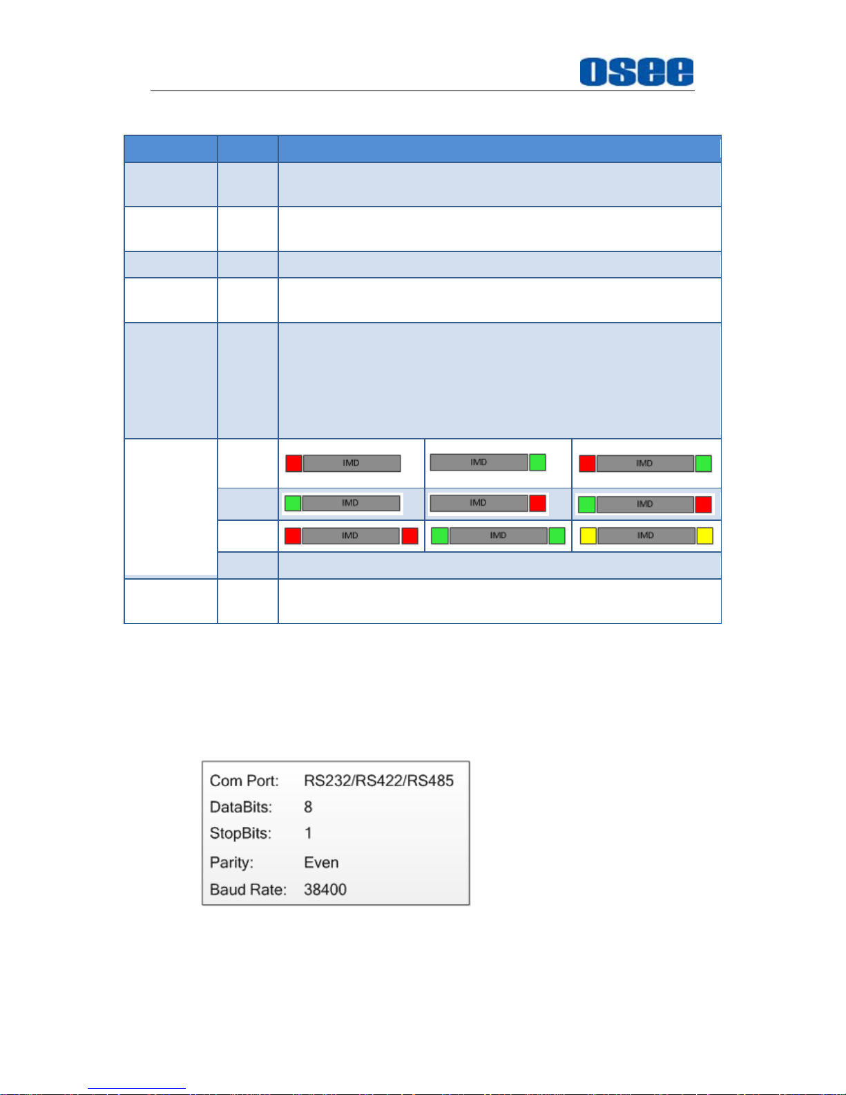
Functionality of the Main Menu
62
IMD Items
Items Value Description
IMD
DISPLAY
ON
IMD
PROTOCAL
TSL3.1
it could receive the data of TSL4.0 protocol
IMD ID 0
BAUD
RATE
38400
LED TALLY ON
It will display as the result of OR relationship of LEFT OSD Tally
and RIGHT OSD Tally. When only one of the two lights is lit, the
LED Tally will light in the same color as the lit OSD Tally’s,
otherwise, when the two lights of OSD Tally are lit, the LED
Tally will light in yellow. (This rule is not fit for LED Tally when
the OSD TALLY MODE item is set to be GR.)
OSD TALLY
MODE
RG
GR
RGY
OFF Close the OSD TALLY
TALLY
SOURCE
TSL
2. TSL4.0
Set
IMDIMD Protocol
item to be TSL4.0, the monitor could receive the
tally control command from a TSL Tally controller or other control devices
conforming to TSL4.0 protocol.
Physical characteristic
IMD Items
Page 69
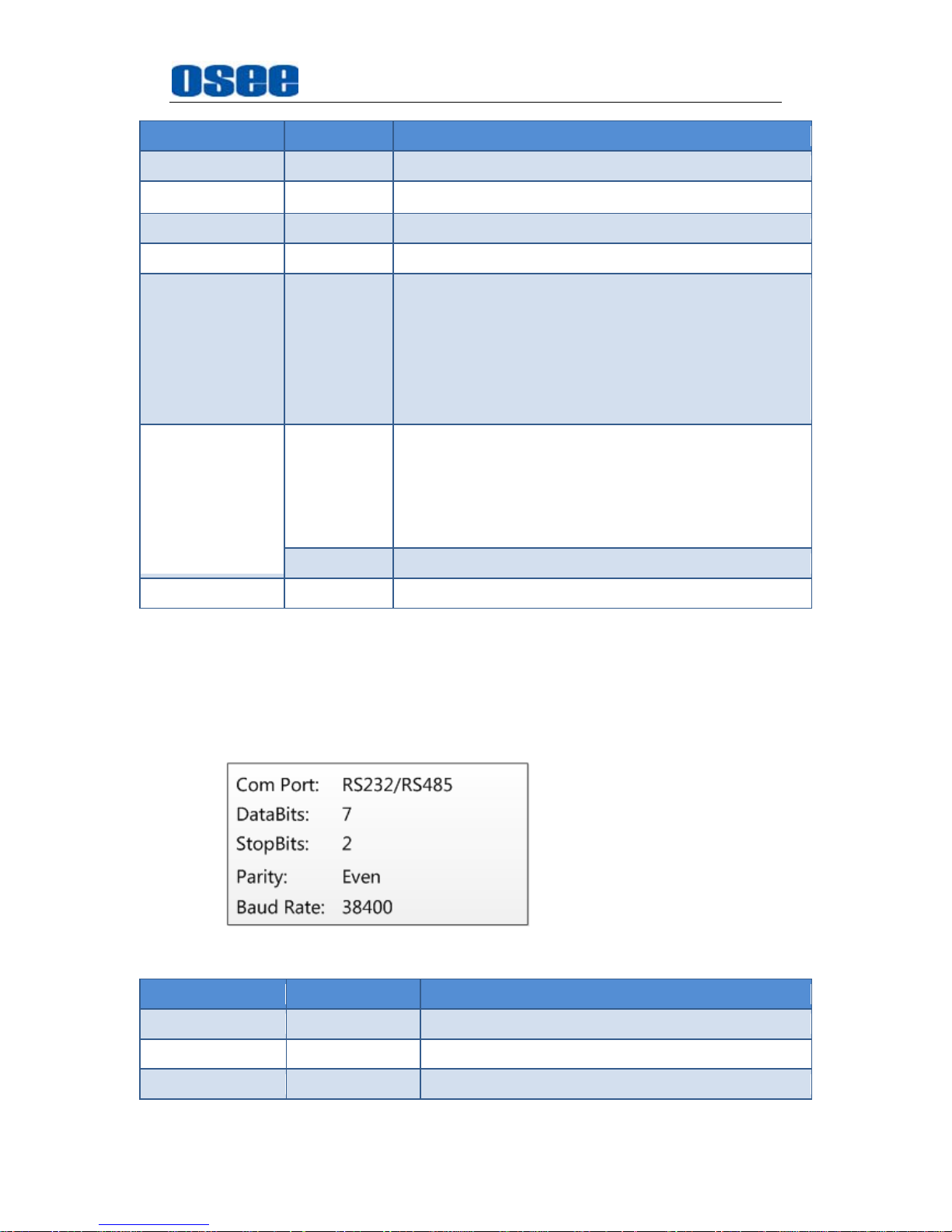
Functionality of the Main Menu
63
Items Value Description
IMD DISPLAY ON
IMD PROTOCAL TSL4.0
IMD ID 0
BAUD RATE 38400
LED TALLY ON
It will display as the result of OR relationship of LEFT
OSD Tally and RIGHT OSD Tally. When only one of
the two lights is lit, the LED Tally will light in the same
color as the lit OSD Tally’s, otherwise, when the two
lights of OSD Tally are lit, the LED Tally will light in
yellow. (This rule is not fit for LED Tally when the
OSD TALLY MODE item is set to be GR.)
OSD TALLY
MODE
RG/GR/RGY
Select anyone of these three items to open the OSD
TALLY, the color and the status of the LEFT OSD
TALLY and RIGHT OSD TALLY will comfort to the
receiving instructions of the corresponding TSL
protocol.
OFF Close the OSD TALLY
TALLY SOURCE TSL
3. Image Video
Set
IMDIMD Protocol
item to be IMAGE VIDEO, the monitor could
receive the tally control command from an IMAGE VIDEO controller or
other control devices conforming to IMAGE VIDEO protocol.
Physical characteristic
IMD Items
Items Value Description
IMD DISPLAY ON
IMD PROTOCAL IMAGE VIDEO
IMD ID 0
Page 70
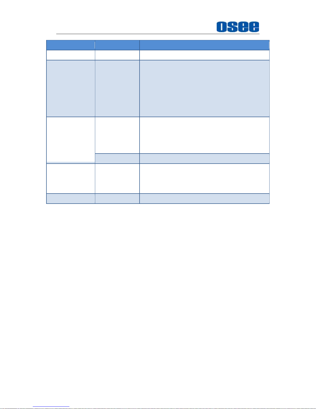
Functionality of the Main Menu
64
Items Value Description
BAUD RATE 38400
LED TALLY ON
It will display as the result of OR relationship of
LEFT OSD Tally and RIGHT OSD Tally. When
only one of the two lights is lit, the LED Tally will
light in the same color as the lit OSD Tally’s,
otherwise, when the two lights of OSD Tally are
lit, the LED Tally will light in yellow. (This rule is
not fit for LED Tally when the OSD TALLY MODE
item is set to be GR.)
OSD TALLY
MODE
RG/GR/RGY
Select anyone of these three items to open the
OSD TALLY, the color and the status of the LEFT
OSD TALLY and RIGHT OSD TALLY will comfort
to the receiving instructions of the IMAGE VIDEO
protocol.
OFF Close the OSD TALLY
IMD TALLY
MODE
T1
T1/T2/T1T2/T2T1/T1-/T2-/T1T2-/T2T1-(Comfort
to the receiving instructions of the IMAGE VIDEO
protocol, refer to IMAGE VIDEO protocol for
details)
TALLY SOURCE IMAGE VIDEO
The monitor supports the following command set in IMAGE VIDEO 1510
protocol: D(d), S(s), C(c), J(j), O(o), U(u), Z(z). And the following
command set are not supported currently: F(f), T(t), A(a), 1Y(y), I(i), 1L(l),
V(v), Q(q), N(n),X(x).
We has only one IMD information on the screen, so in S(s) command, the
line number for the UMD text can just be 1, for example, the command
should be:
%0D%1Sone line%z.
4. TSL5.0
Set
IMDIMD Protocol
item to be TSL5.0, the monitor could receive the
tally control command from network devices conforming to UDP protocol.
Physical characteristic
Use RJ45 interface in UDP protocol, the maximum length of data package
is 2048 Bytes, and the port number is 5000.
5.2 Menu Settings
When checking or modifying the value of the menu item, cooperating with the
following buttons: MENU, ∧(Up), ∨(Down), ENTER.
1. Operations to the Main menu
Page 71
Functionality of the Main Menu
65
Display the Main Menu
Press MENU button to enter into the main menu, it displays at the top
left corner of the screen.
Switch menu items
After displaying the main menu, press ∧(Up) or ∨(Down) button to
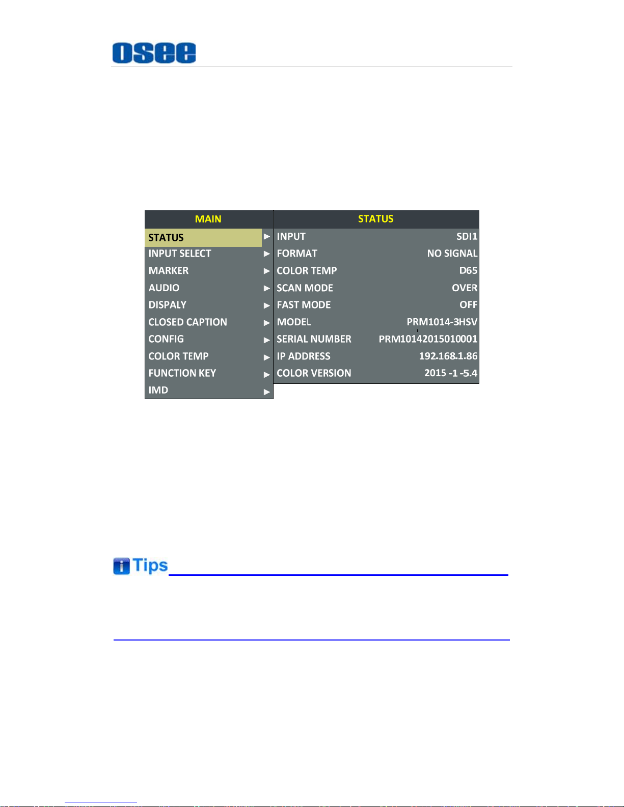
choose a menu item, the menu item selected is in yellow. For example,
you have selected Status menu, as shown in Figure 5.2-1.
Figure 5.2-1 Selecting STATUS Menu
Back to the Main menu
After entering to a sub-menu item or a sub-menu item value, press
MENU button to back to the upper level menu area.
Close the Main menu
Press MENU button to close the Main menu when the control icon is in
the Main menu item.
After you have loaded the Main menu, it will be closed automatically if you
do nothing operation with it in 60s.
2. Operations to sub-menu item
Display the sub-menu item
After display the Main menu, press ∧(Up) or ∨ (Down) button to
select a menu item, and the right part displays its sub-menu items
Page 72
Functionality of the Main Menu
66
according to the current selected menu item.
Switch sub-menu items
After displaying the sub-menu items list, press ENTER button to enter
into the sub-menu items list, press ∧(Up) or ∨ (Down) button to
choose a sub-menu item, a yellow rectangle is in front of the selected
sub-menu item.
Back to menu item
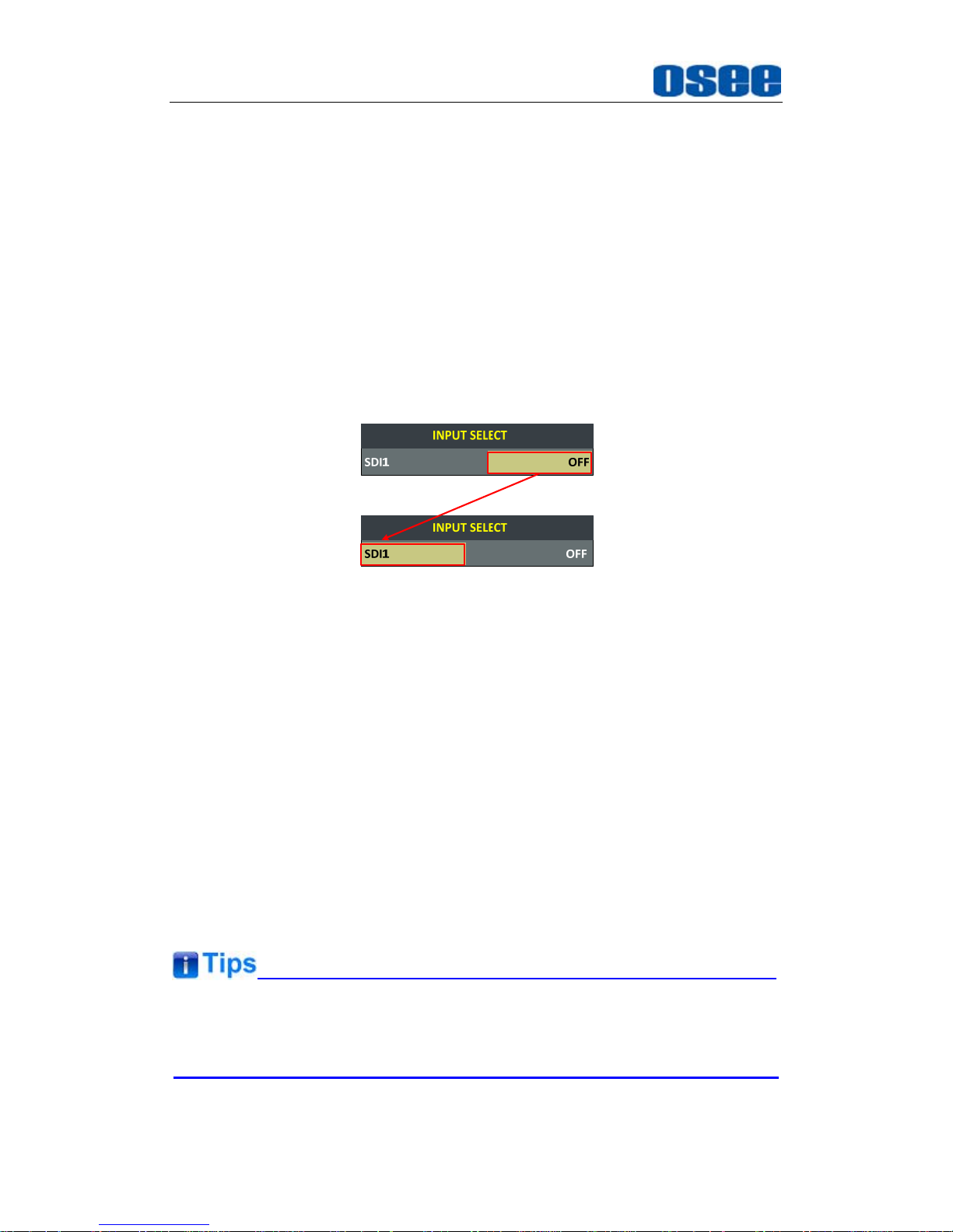
After entering to the sub-menu item value, press MENU button to back
to menu items, or after setting the sub-menu item value and press Enter
button to firm the modification, the control icon is back to the
corresponding sub-menu item, as shown in Figure 5.2-2:
Figure 5.2-2 The Control Icon Moves from the Sub-menu Item Value to
the Corresponding Sub-menu Item
3. Operations to sub-menu item value
Switch sub-menu item value
When the control icon is in sub-menu item value, press ∧(Up) or ∨
(Down) button to switch among its value list.
Confirm the modification to sub-menu item value
Press ENTER button to confirm the selection of a value, and the control
icon is back to the corresponding sub-menu item.
Abandon the modification to sub-menu item value
Press MENU button to give up the modification to sub-menu item value,
and the control icon is back to the corresponding sub-menu item.
The value in white color is modifiable, and the value in blue color is
unmodifiable.
4. Selecting the Menu Language
Page 73
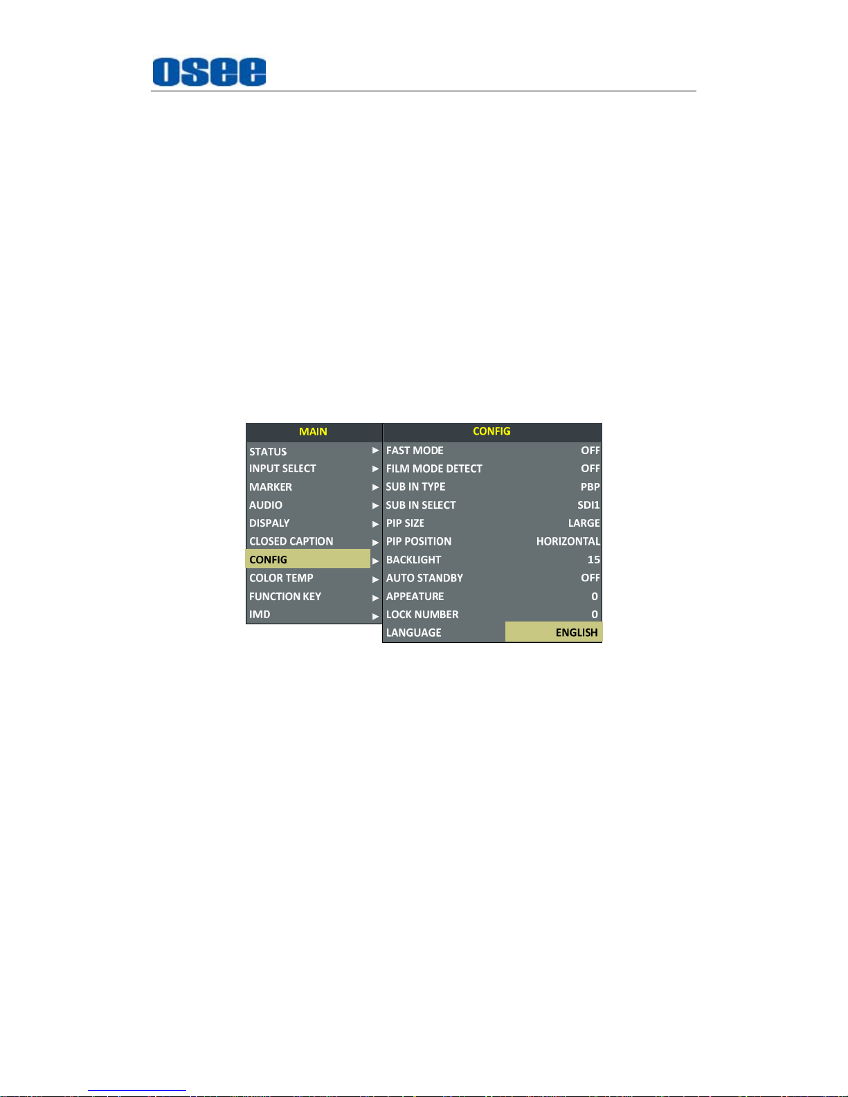
Functionality of the Main Menu
67
You can select one of languages (English or Chinese) for displaying the
menu. The default language for the menu is ENGLISH. The following
will teach you how to switch to Chinese.
Operation:
Step 1 Select CONFIG menu
Press MENU button to display the OSD menu, click ∨(down) button to
select CONFIG menu.
Step 2 Select the value of the Language item
Press ENTER button to get into the CONFIG menu items, and click ∨
(down) button to select the sub-item LANGUAGE, then, click ENTER
button to get into the sub-value list, as shown in Figure 5.2-3, the
current control icon is in ENGLISH.
Figure 5.2-3 Select the Value of Language
Step 3 Confirm the modification of the value of sub-item
Click ∨(down) button to select the sub-item LANGUAGE to Chinese,
as shown in Figure 5.2-4, press ENTER button to confirm the
modification.
Page 74
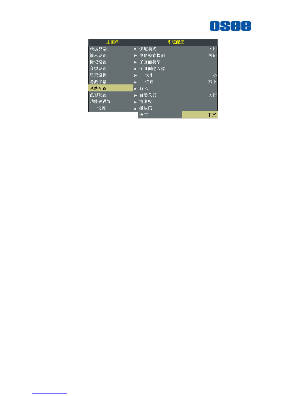
Functionality of the Main Menu
68
PIP
PIP
PBP
SDI1
15
0
0
IMD
Figure 5.2-4 Switching the Value of LANGUAGE
Step 4 Exit the main menu
Click MENU button to exit the main menu.
Page 75
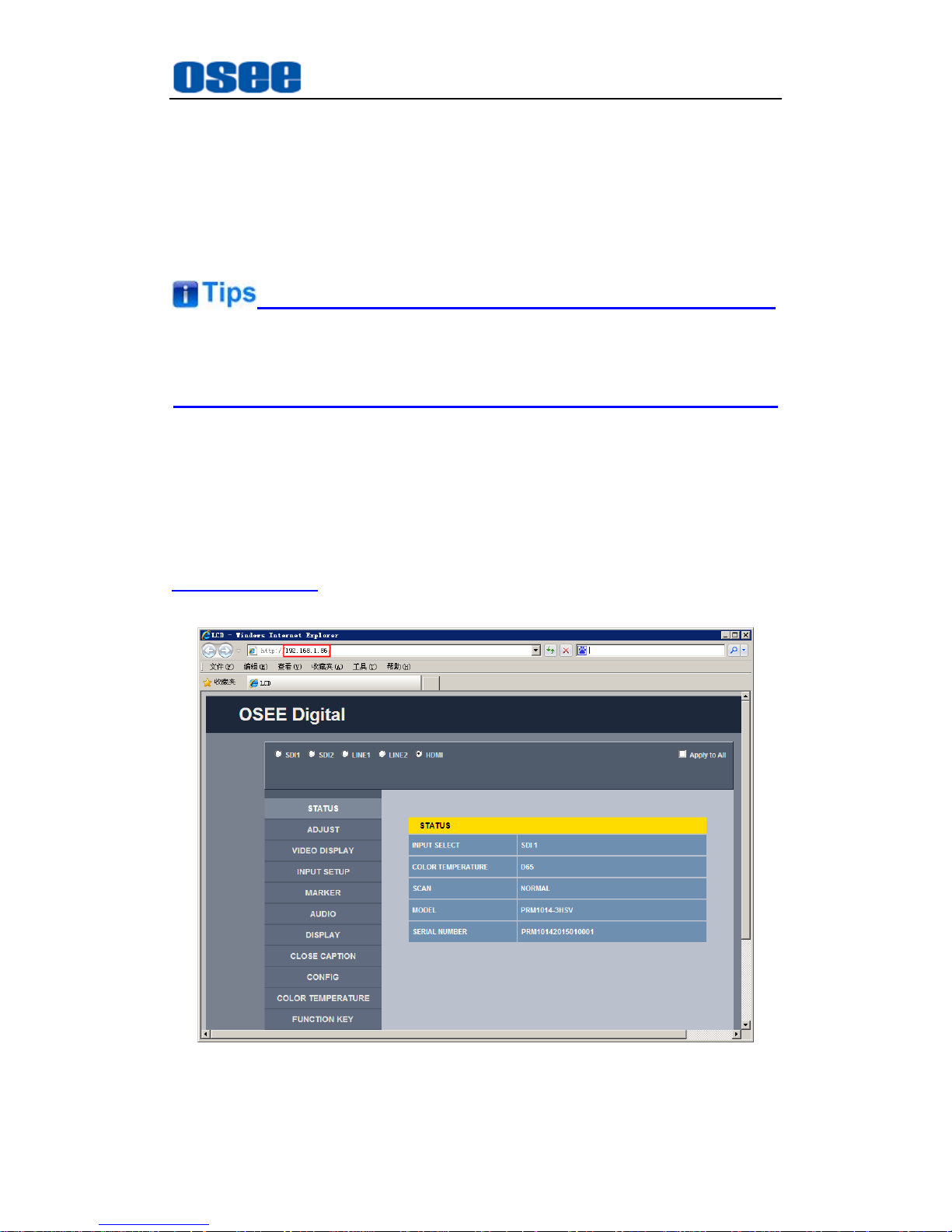
Network Control
69
Chapter 6 Network Control
PRM1014 supports network interface. Connect a computer with PRM1014
through this interface to achieve the network control to PRM1014.
The network address of the computer which is connected with PRM1014
and the network address of PRM1014 must be in the same segment.
This chapter will introduce how to set and check the parameters of PRM1014
in Internet Explorer.
6.1 Access the settings
Use Internet Explorer to enter into a web control page. For example, input
http://192.168.1.86 in address bar, it will display the then, press Enter key, the
management interface of PRM1014 is shown as in Figure 6.1-1:
Figure 6.1-1 Network Control Page
Page 76
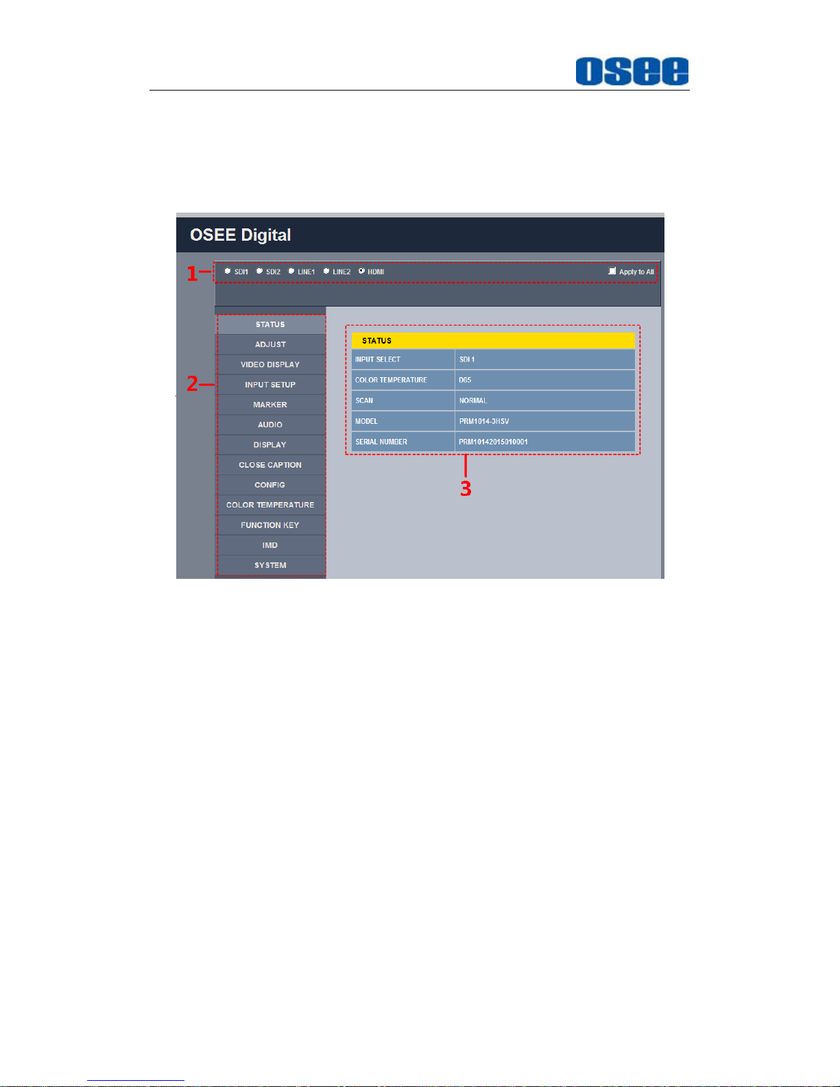
Network Control
70
6.2 Menu Control
Open the management interface as shown in Figure 6.2-1, the menu items
listed in the left part are almost as the same as the main menu items.
Figure 6.2-1 Management Interface
As shown in Figure 6.2-1, the management interface is divided into the
following parts:
1. Input Source Selection Button
It is used to selecting an input source as the input signal, such as: SDI1,
SDI2, LINE1, LINE2, HDMI. The selecting box of "Apply to All" at the
right side is used to synchronize the settings of a signal source to
another signal source.
2. Navigation menu list
It shows the navigation menus: STATUS, ADJUST, VIDEO DISPLA Y ,
INPUT SETUP, MARKER, AUDIO, DISPLAY, CLOSE CAPTION,
USER CONFIG, COLOR TEMPERATURE, FUNCTION KEY, IMD and
SYSTEM. Click the navigation menu, it will show the corresponding
settings on the right side. The menu items in main menu on screen
display are mostly as the same as the menu items listed in navigation
menus except SYSTEM.
Page 77
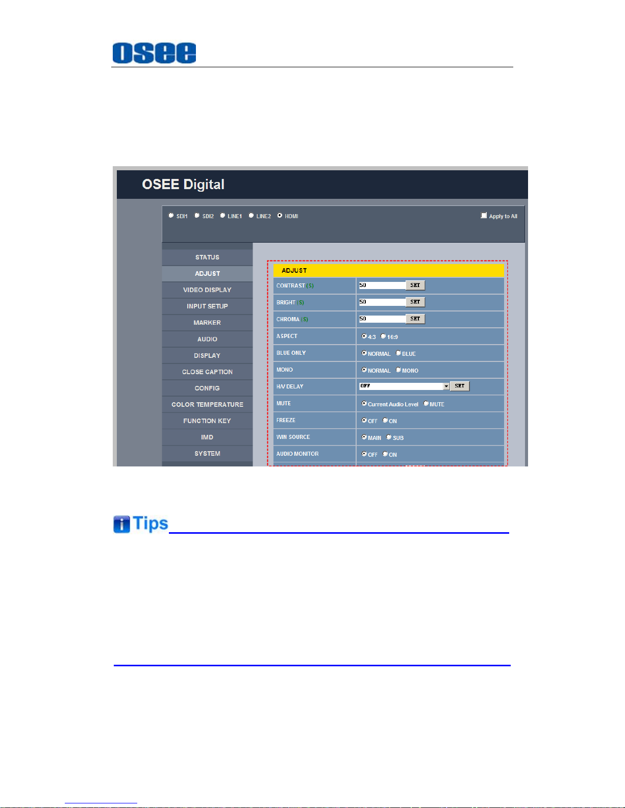
Network Control
71
3.
Parameter list
It shows the parameter names, values and operation buttons of the
selected navigation menu, as shown in the red rectangle in Figure 6.2-2.
The title in the yellow rectangle of the parameter list and the parameter
list will change with the navigation menu when switched.
Figure 6.2-2 Parameter List
There may be a “(S)” icon followed by some parameter name in the
parameter list, it is mean that this parameter is only a local parameter for
the current selected monitor, otherwise, the parameter is global and the
modification is valid for both screens.
The SET button is used to confirm the modification of the parameter value.
Page 78
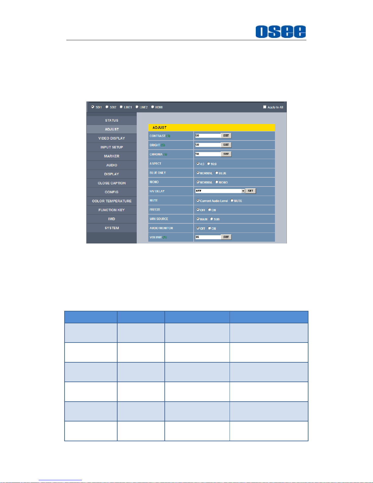
Network Control
72
6.2.1 ADJUST Menu
It will introduce ADJUST menu.
Click
ADJUST
button at the left navigation menu list, it will display the
adjust parameters, as shown in Figure 6.2-3:
Figure 6.2-3 ADJUST Menu
The relationship of Items, Default Value, Domain Range and Description
of the sub-item is shown in Table 6.2-1:
Table 6.2-1 The Description of ADJUST Menu Items
Items Default Value Domain Range Description
CONTRAST 50 0~100
A
djust the picture
contrast
BRIGHTNESS 50 0~100
A
djust the picture
brightness
CHROMA 50 0~100
A
djust the picture
monochroma
ASPECT 16:9 4:3/16:9
Set the aspect ratio of
the picture
BLUE ONLY NORMAL NORMAL/BLUE
Enable/disable Blue
Only mode
MONO NORMAL NORMAL/MONO
Enable/disable
Monochrome mode,
Page 79
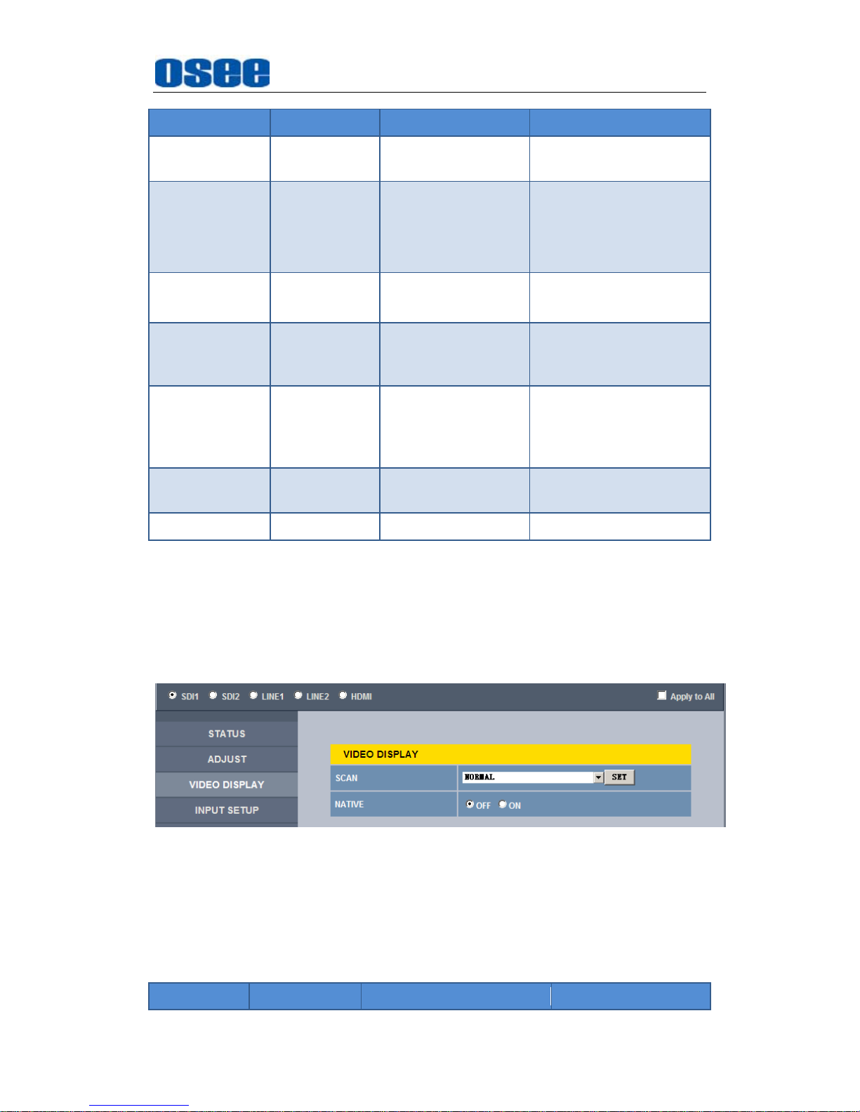
Network Control
73
Items Default Value Domain Range Description
normal mode is actually
the color mode
H/V DELAY OFF
OFF
H DELAY
V DELAY
H/V DELAY
Display synchronizing
signals in horizontal or
vertical mode
MUTE
Current Audio
Level
Current Audio Level
MUTE
Enable/disable the audio
monitor
FREEZE OFF OFF/ON
Enable/disable the
current picture to be
stopped or played.
WIN SOURCE MAIN MAIN/SUB
Set the picture
displaying mode in full
mode or in sub-picture
mode
AUDIO
MONITOR
OFF OFF/ON
Set whether in audio
monitoring.
VOLUME 16 0~31 Adjust the volume
6.2.2 VIDEO DISPLAY Menu
It will introduce VIDEO DISPLAY menu.
Click
VIDEO DISPLAY
button at the left navigation menu list, it will display
the video display parameters, as shown in Figure 6.2-4:
Figure 6.2-4 VIDEO DISPLAY Menu
The relationship of Items, Default Value, Domain Range and Description
of the sub-item is shown in Table 6.2-2:
Table 6.2-2 The Description of VIDEO DISPLAY Menu Items
Items Default Value Domain Range Description
Page 80
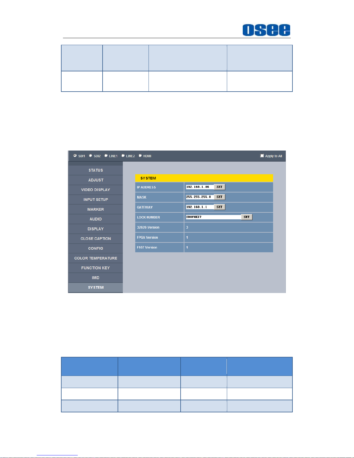
Network Control
74
SCAN NORMAL
NORMAL
OVERSCAN
UNDERSCAN
Set the scan mode
NATIVE OFF OFF/ON
Whether to display
the picture dot by dot
6.2.3 SYSTEM Menu
It will introduce SYSTEM menu.
Click
SYSTEM
button at the left navigation menu list, it will display the
system parameters, as shown in Figure 6.2-5:
Figure 6.2-5 System Menu
The relationship of Items, Default Value, Domain Range and Description
of the sub-item is shown in Table 6.2-3:
Table 6.2-3 The Description of System Menu Items
Items Default Value
Domain
Range
Description
IP 192.168.1.86 -
IP address
MASK 255.255.255.0 -
Subnet mask
Gateway 192.168.1.1 -
Gateway address
Page 81
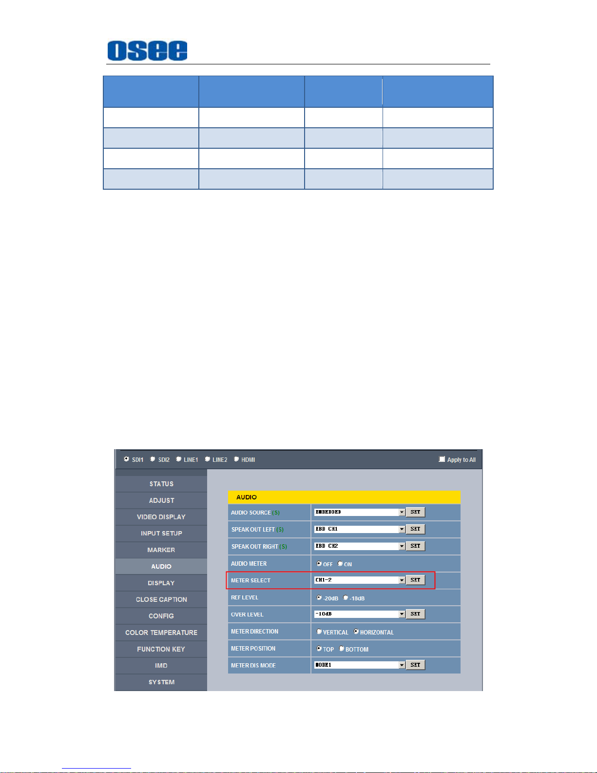
Network Control
75
Items Default Value
Domain
Range
Description
LOCK NUMBER 0001 -
Serial Number
32626 Version
3 -
Product information
FPGA Version
1 -
Product information
F107 Version
1 -
Product information
6.2.4 Other Menus
For the menu items in management interface are almost as the same as
the menu items in the Main menu on screen, there will be no further
description about their meanings and value range in this chapter, refer to
“Chapter 5 Functionality of the Main Menu” for the details about
STATUS
,
VIDEO CONFIG, AUDIO CONFIG, MARKER, DISPLAY, USER CONFIG
,
and
COLOR TEMPERATURE
.
6.3 Parameter Settings
It will introduce how to modify parameter values in management interface in
the followings.
For example: modify Meter Select in AUDIO menu. Click AUDIO button to
display its parameter list, as shown in Figure 6.3-1, the corresponding screen
main menu is shown as in Figure 6.3-2:
Page 82
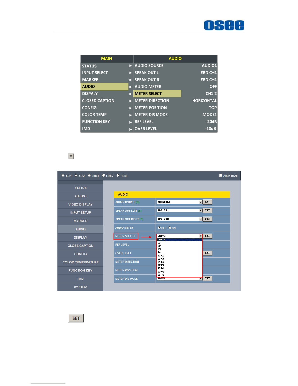
Network Control
76
Figure 6.3-1 Parameter List for AUDIO
Figure 6.3-2 Screen Main Menu for AUDIO
Click button to display the drop-down value list for the parameter, as shown
in Figure 6.3-3, for example, modify “CH1-2” to “G1”.
Figure 6.3-3 Display the Drop Down Value List of Meter Select(S)
Click button to confirm the selection and the page is refreshed. You
can check the modification on the screen menu, the results are the same as
shown in Figure 6.3-4 and Figure 6.3-5:
Page 83
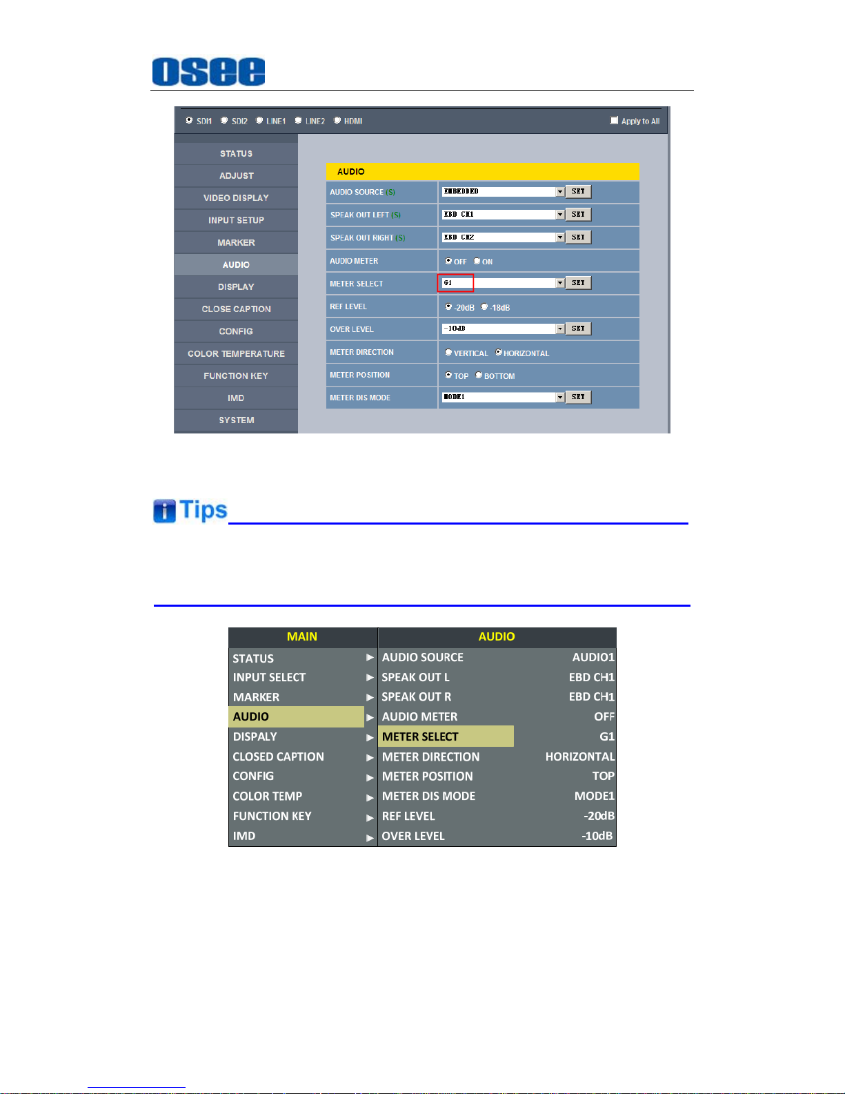
Network Control
77
Figure 6.3-4 Modify the Value of a Parameter
The volume can be checked and modified in adjust menu on screen
adjustment, or in
Volume
item of
ADJUST
menu in management interface.
Figure 6.3-5 The Value is Modified Simultaneously on Screen Menu
Likewise, if you modify the value of a parameter on screen menu first, you may
check the same changing result in management interface through network
connection.
Page 84

78
Page 85
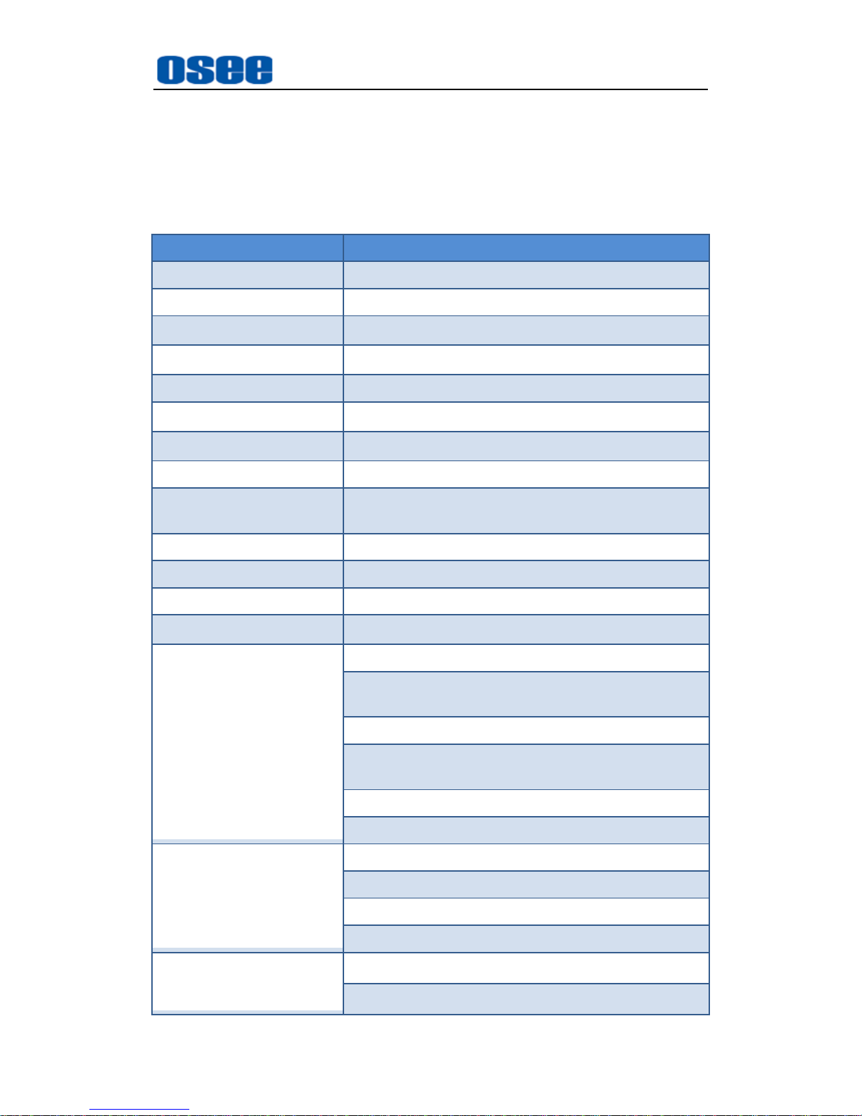
Specifications
79
Chapter 7 Specifications
1.
Product detailed information
Specification Values
Number of Screens 1
Aspect Ratio 16:10
Display Area(mm)
216.81(H)×135.50(V)
Viewing Angle
178°(H)x178°(V)
Color Depth 16.7M colors (RGB 8-bits)
Resolution
1920(H)×1200(V)
Dot Pitch(mm)
0.113(H)×0.113(V)
Contrast 800:1
Brightness(cd/㎡)
400 typ. (5 points average)
340 min. (5 points average)
Response Time (ms Typ.) <25
Backlight WhiteLED
Backlight Life(Hrs) 20000
Work Temperature
0°C~35°C
Signal Formats
SD: 480ip59.94, 576i50
HD: SMPTE-274M: 1080i 50/59.94,1080p/PsF
23.98/24/25
HD: SMPTE-296M: 720p 50/59.94
3G: SMPTE-425 level A(mapping 1): 1080p
50/59.94
HDMI 1.3a
Compliant to EIA/CEA-861-D
Input
3G/HD/SD-SDI Input(75Ohm BNCx2)
Analog Composite (75Ohm BNCx2)
HDMI Input(HDMI Type A)
Analog stereo input(RCAx4)
Output
3G/HD/SD-SDI Input(BNCx2)
Analog stereo output (RCAx2)
Page 86
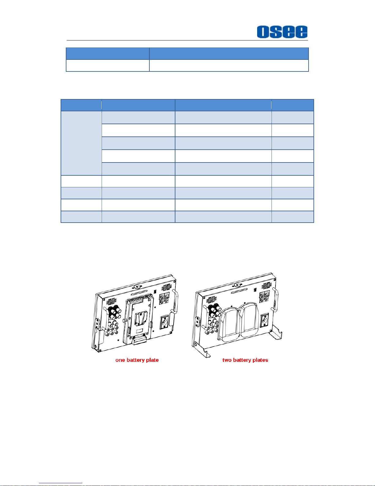
Specifications
80
Specification Values
Stereo HEADPHONE (3.5mm stereo Jack)
2. Optional Accessories
You can select the following accessories for PRM1014 optionally:
Type Model Description Amount/per
Battery
Plate
PRM1014-A-BM-V
V-mount battery plate
1
PRM1014-A-BM-AB
AB-mount battery plate
1
PRM1014-BP-970
SONY F-970 battery plate
1/2
PRM1014-BP-D54S
Panasonic D54S Battery Plate
1/2
PRM1014-BP-E6
Canon LP-E6 Battery Plate
1/2
Hanger PRM-HS Hot shoe mount 1
Hanger PRM-MH Magic arm 1
Monitor bag PRM-PP Monitor bag 1
Sun shade PRM-SHD Sun shade 1
If you want to use a battery as your backup power supply, you can choose
the battery plate listed in the optional accessories table above, and you
can select two types of battery plate according to your needs: one battery
plate or two battery plates, as shown in the following figure:
3. Dimensions
The description of the product dimensions of PRM1014 is shown as in the
following figures:
Page 87
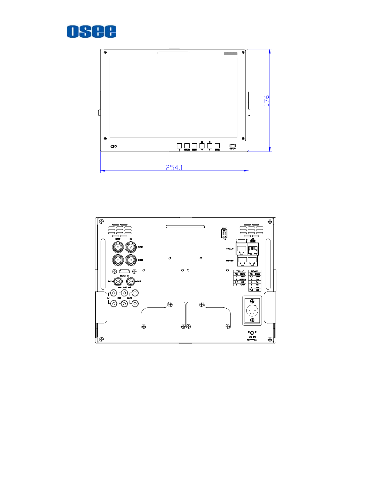
Specifications
81
Figure 7-1 Front Panel(Unit: mm)
Figure 7-2 Rear Panel(Unit: mm)
Page 88
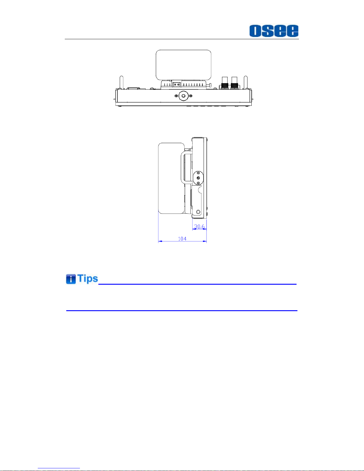
Specifications
82
Figure 7-3 Top View(Unit: mm)
Figure 7-4 Side View(Unit: mm)
Specifications are subject to change without notice.
------------------No Text Below------------------
Page 89

FOR MORE INFORMATION PLEASE VISIT: http://www.osee-dig.com/
OSEE TECHNOLOGY CO., LTD.
No.22 Building, No.68 zone, Beiqing Road, Haidian District, Beijing, China
Tel: (+86) 010-62434168, Fax: (+86) 010-62434169
E-mail: [email protected]
 Loading...