

Page 1

MVM-170 MVM-200 Series
Quad Split LCD Monitor
User Manual
Page 2

Page 3

Product Information
Model:
MVM-170 MVM-200 Series Quad Split LCD Monitor
Version:
V010100
Release Date:
September 27th, 2016
Company
OSEE TECHNOLOGY CO., LTD.
Contact Information
Address:
No.22 Building, No.68 zone, Beiqing Road, Haidian District,
Beijing, China
Post Code:
100094
Tel:
(+86) 010-62434168
Fax:
(+86) 010-62434169
Web:
http://www.osee-dig.com/
E-mail:
Page 4
About this manual
Important
The following symbols are used in this manual:
The further information or know-how for described subjects above which
helps user to understand them better.
The safety matters or operations that user must pay attention to when
using this product.
Contents
The user manual applies to the following device types:
MVM-170-3HSV
MVM-170-HSV
MVM-170-SV
MVM-200-3HSV
MVM-200-HSV
MVM-200-SV
The above listed devices have most similarities on appearance and
characteristics. The images of MVM-200-3HSV are adopted in the following
descriptions.
Any of the different specifications between the device types are elaborated.
Before reading the manual, please confirm the device type.
Page 5

I
Contents
Contents .......................................................................................................... I
Chapter 1 Overview ....................................................................................... 1
Chapter 2 Safety ............................................................................................. 3
Chapter 3 Unpack and Installati on ............................................................... 7
Chapter 4 MVM-200 Features ...................................................................... 13
4.1
Front Panel Features ........................................................................ 16
4.1.1 Arrangement of Front Panel ........................................................... 16
4.1.2 Operation of Front Panel ................................................................ 17
4.1.3 Display Mode .................................................................................. 20
4.2
Rear Panel Features .......................................................................... 23
4.2.1 Arrangement of Rear Panel ............................................................ 23
4.2.2 Operations of Rear Panel ............................................................... 24
4.3
Supported Signal Format ................................................................. 26
Chapter 5 Functionality of the Main Menu ................................................. 29
5.1
Main Menu ......................................................................................... 30
5.1.1 STATUS Menu ............................................................................... 31
5.1.2 COLOR TEMP Menu ...................................................................... 32
5.1.3 MARKER Menu .............................................................................. 33
5.1.4 ALARM CONFIG Menu .................................................................. 36
5.1.5 AUDIO CONFIG Menu ................................................................... 37
5.1.6 USER CONFIG Menu ..................................................................... 39
5.1.7 OSD CONFIG Menu ....................................................................... 42
5.2
Menu Settings .................................................................................... 46
Chapter 6 Specifications ............................................................................. 49
Page 6

Page 7
Overview
1
Chapter 1 Overview
The MVM-170/MVM-200 series Quad Split LCD Monitor are high-performance
professional LCD monitor featuring quad split display. It supports high quality
quad split displays and is designed to tailor the extensive needs for
programming, concentrated on download and upload, broadcast master
control, studio, centralized monitoring and so on.
The MVM-170/MVM-200 series Quad Split LCD Monitor supports the
advanced 10- bit digital processing technology and also supports 3D comb
filter and de-interlace, accurate scaling engine, GAMMA and color temperature
adjustment function, in order to achieve the best possible image display. Each
display screen of the monitor is an independent professional monitor. So it can
achieve the various professional parameters and can be adjusted
independently, including GAMMA, color temperature, brightness, and so on.
The MVM-170/MVM-200 series Quad Split LCD Monitor supports 4ch
3G/HD/SD-SDI/CVBS signal and 1-way HDMI / DIV-D signal input. It can
simultaneously display four signal inputs, with three typical display modes
(including one full screen display, one - big with three - small screen display
and four uniform size screen display). Each display screen can achieve
professional monitor display functions, including embedded audio solution,
audio monitoring, audio meter display, TC code display, IMD, various Markers
and so on.
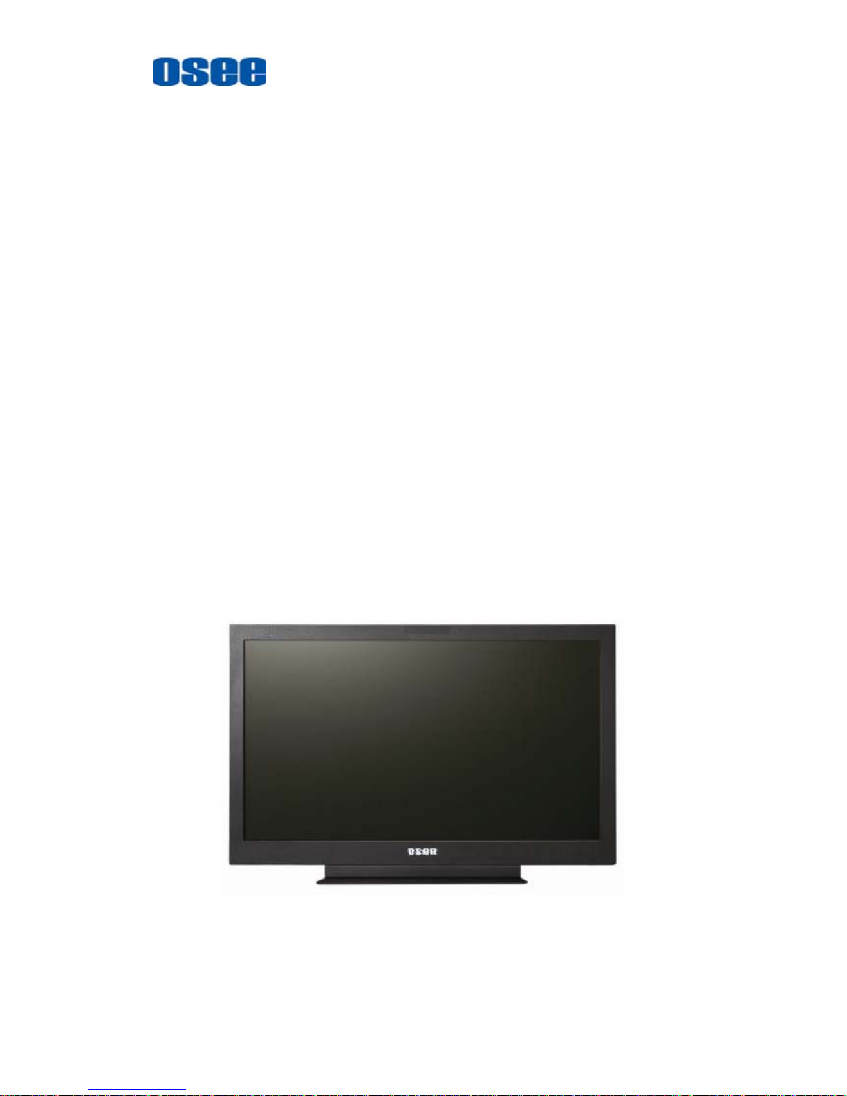
Figure 1 A Diagram of MVM-200 Monitor
Features
Page 8

Overview
2
178-degree viewing angle
Multi-format analog and digital audio signals
Support select 4 from 5 input signals to display
Support a single screen display as a professional monitor
Support the independent adjustment of the parameters for single
screen
With all the important functions of multi-view processor
Support high-quality waveform, vector monitoring
Support HDMI output or HD-SD display, can achieve the cascade and
copy output of devices
Functionality
Supports MARKER, Time Code, MET display
Supports presetting the color temperature using customized values
Page 9

Safety
3
Chapter 2 Safety
FCC Caution:
Any Changes or modifications not expressly approved by the party responsible
for compliance could void the user's authority to operate the equipment.
This device complies with part 15 of the FCC Rules.
Operation is subject to the following two conditions: (1) This device may not
cause harmful interference, and (2) this device must accept any interference
received, including interference that may cause undesired operation.
Note: This equipment has been tested and found to comply with the limits for a
Class B digital device, pursuant to part 15 of the FCC Rules. These limits are
designed to provide reasonable protection against harmful interference in a
residential installation. This equipment generates uses and can radiate radio
frequency energy and, if not installed and used in accordance with the
instructions, may cause harmful interference to radio communications.
However, there is no guarantee that interference will not occur in a particular
installation. If this equipment does cause harmful interference to radio or
television reception, which can be determined by turning the equipment off and
on, the user is encouraged to try to correct the interference by one or more of
the following measures:
Reorient or relocate the receiving antenna.
Increase the separation between the equipment and receiver.
Connect the equipment into an outlet on a circuit different from that to which
the receiver is connected.
Consult the dealer or an experienced radio/TV technician for help.
Page 10
Safety
4
Warnings:
Read, keep and follow all of these instructions for your safety. Heed all
warnings.
Device
Install in accordance with the manufacturer's instructions.
Do not beat with a hard object or scratch the LCD display.
Do not make the freeze picture displaying on the screen time too long,
otherwise, it will leave the afterimage on the screen.
If the brightness is adjusted to the minimum, then it might be hard to
see the display screen.
Refer all servicing to qualified service personnel. Servicing will be
required under all of the following conditions:
The unit has been exposed to rain or moisture.
Liquid had been spilled or objects have fallen onto the unit.
The unit has been damaged in any way, such as when the
power-supply cord or plug is damaged.
The unit does not operate normally.
Clean only with dry cloth.
Specifications are subject to change without notice.
Position
Do not block any ventilation openings.
Do not use this unit near water.
Do not expose the unit to rain or moisture.
Do not use this unit near any heat sources such as radiators, heat
registers, stoves, or other apparatus (including amplifiers) that product
Page 11
Safety
5
heat.
Do not place objects filled with liquids, such as vases, cups, etc. on or
over the device.
A nameplate indicating operating voltage, etc., is located on the rear
panel.
The socket-outlet shall be installed near the equipment and shall be
easily accessible.
Power Supply Cord
Do not defeat the safety purpose of the polarized or grounding-type
plug.
Do not damage the power cord, place the heavy objects on the power
cord, stretch the power cord, or bend the power cord.
Protect the power cord from being walked on or pinched, particularly at
plugs, convenience receptacles, and the point where they exit from the
unit.
If the power cord is damaged, turn off the power immediately. It is
dangerous to use the unit with a damaged power cord. It may cause
fire or electric shock.
Unplug this unit during lighting storms or when unused for long periods
of time.
Disconnect the power cord from the AC outlet by grasping the plug, not
by pulling the cord.
Should any solid object or liquid fall into the cabinet, unplug the unit
and have it checked by qualified personnel before operating it any
further.
Page 12

6
Page 13

Unpack and Installation
7
Chapter 3 Unpack and Installation
Unpack:
When unpacking the components of MVM-200 monitor, please verify that none
of the components listed in Table 3.1 are damaged or lack. If there is any
missing, contact your distributors or OSEE for it.
Table 3-1 Packing List
NO. Detail list Quantity
1 Monitor 1
2 Optional Accessory
Monitor Stand 1
Rackmount Bracket 1
Wallmount Bracket 1
Extra control buttons bar 1
3 Accessory
Warranty card 1
Certificate card 1
User manual 1
4 The electric accessory
19V adapter 1
Power cord 1
Installation:
1.
Prepare for installation
Please follow the procedures below before installing MVM-200:
Check the equipment for any invisible damage that may have occurred
during transit.
Confirm all the items listed on the packing list have been received.
Remove all the packing material including electrostatic-resistant
packing.
Retain these packing materials for future use.
2.
Mount a MVM-200 in your desired location of a standard rack.
Adequate ventilation is required when installed to prevent possible
damage to the MVM-200.
3.
Connect required cables for signal input and output. For BNC
connections use 75Ω rated connectors.
Page 14
Unpack and Installation
8
4.
Connect DC18~20V power source using the included power cord.
5. Connect the power cord to the power interface.
6. Fasten the power protect accessory.
7. As a final step, turn on the device by pressing the corresponding
power switch located on the front panel.
The pedestal and the monitor are packaged separately.
Connect a standard signal line to the corresponding input port. All BNC
connector impedance must be 75Ω.
Please use the power cord supplied to avoid unnecessary trouble, and
make sure be well grounded.
The factory default value for IP address is 192.168.1.86.
Installation Methods:
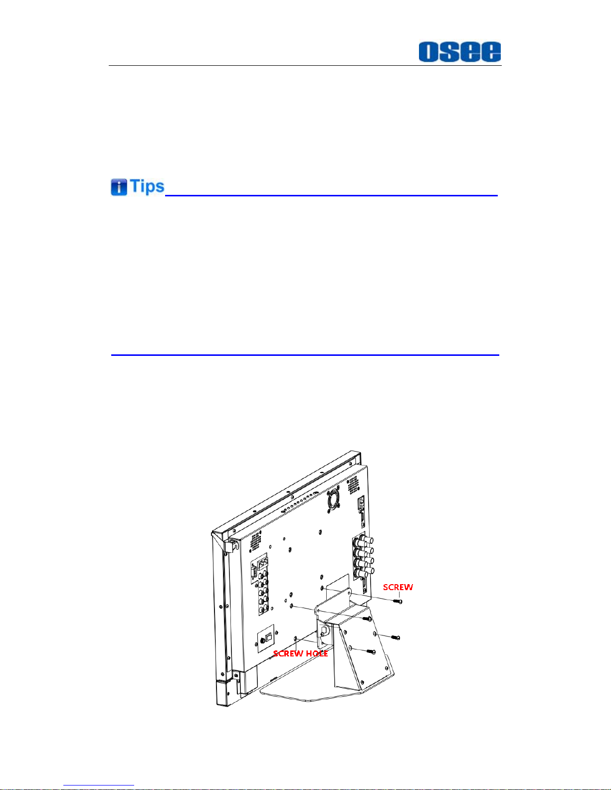
The MVM-200 monitor could be mounted to a monitor stand or mounted to a
cabinet or onto a wall. The MVM-170 monitor could be mounted to a monitor
stand or mounted to a cabinet.
Monitor Stand Installation
Page 15
Unpack and Installation
9
Figure 3-1 Monitor Stand Installation
Cabinet Installation
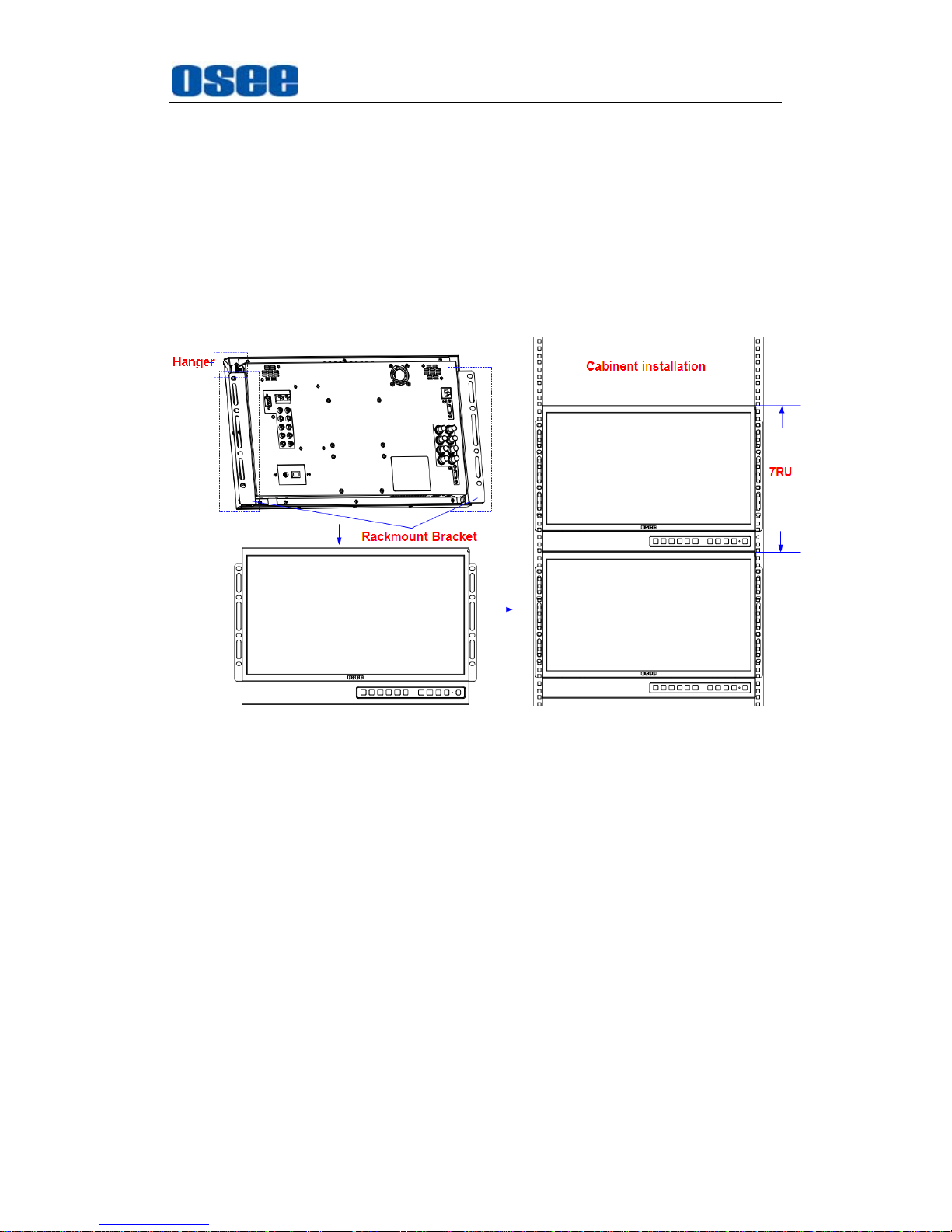
The MVM-200 series monitors support cabinet installation. Firstly,
mount the rackmount brackets to the rear panel of the monitor, fasten
them, then mount the monitor onto the cabinet steadily and firmly.
Buckle the monitor with the hanger at the right top of the monitor on the
rear panel to lock the monitor in case of unexpected rollover.
Figure 3-2 Rackmount Installation
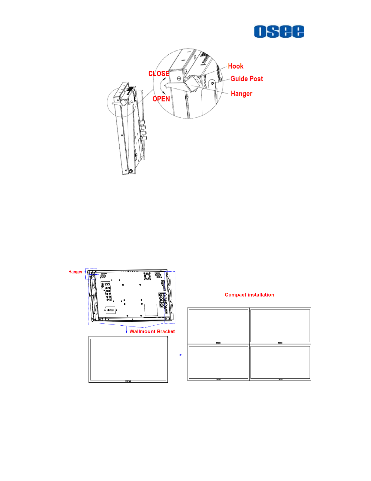
Hanger usage
Rotate the hanger to hook with the locating guide post to lock the
monitor, in case of unexpected rollover.
Page 16
Unpack and Installation
10
Figure 3-3 Hanger Usage
Videowall Installation
The MVM-200 series monitors support compact installation for videowall.
Firstly, mount the wallmount brackets to the rear panel of the monitor,
fasten them, then, mount the monitor onto the videowall frame steadily
and firmly. Buckle the monitor with the hanger at the right top of the
monitor on the rear panel to lock the monitor in case of unexpected
rollover.
Figure 3-4 Wallmount Installation
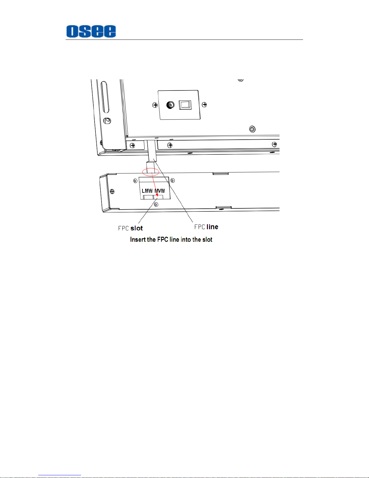
Installation for the extra control buttons bar:
You can use the control buttons on the top of the monitor, or you can
amount an extra control buttons bar at the bottom of the monitor. The
Page 17
Unpack and Installation
11
installation steps of the extra control buttons bar are as follows:
Step 1
: first, insert the FPC line of the monitor to the corresponding slot of
the extra control buttons bar, as shown in the following illustration:
Figure 3-5 FPC Connection
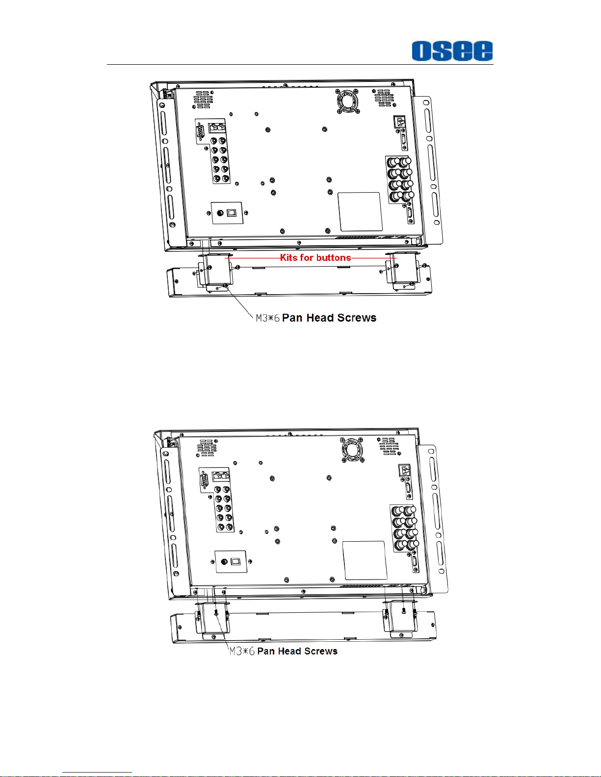
Step 2
: second, mount the extra control buttons bar with the kits at both
sides, fasten them firmly, as shown in the following illustration:
Page 18
Unpack and Installation
12
Figure 3-6 Mount the Kit of the Extra Control Buttons Bar
Step 3
: at last, connect the extra control buttons bar to the monitor with
the pan head screws, fasten them firmly, as shown in the following
illustration:
Figure 3-7 Mount the Extra Control Buttons Bar
Page 19
MVM Monitor Features
13
Chapter 4 MVM Monitor Features
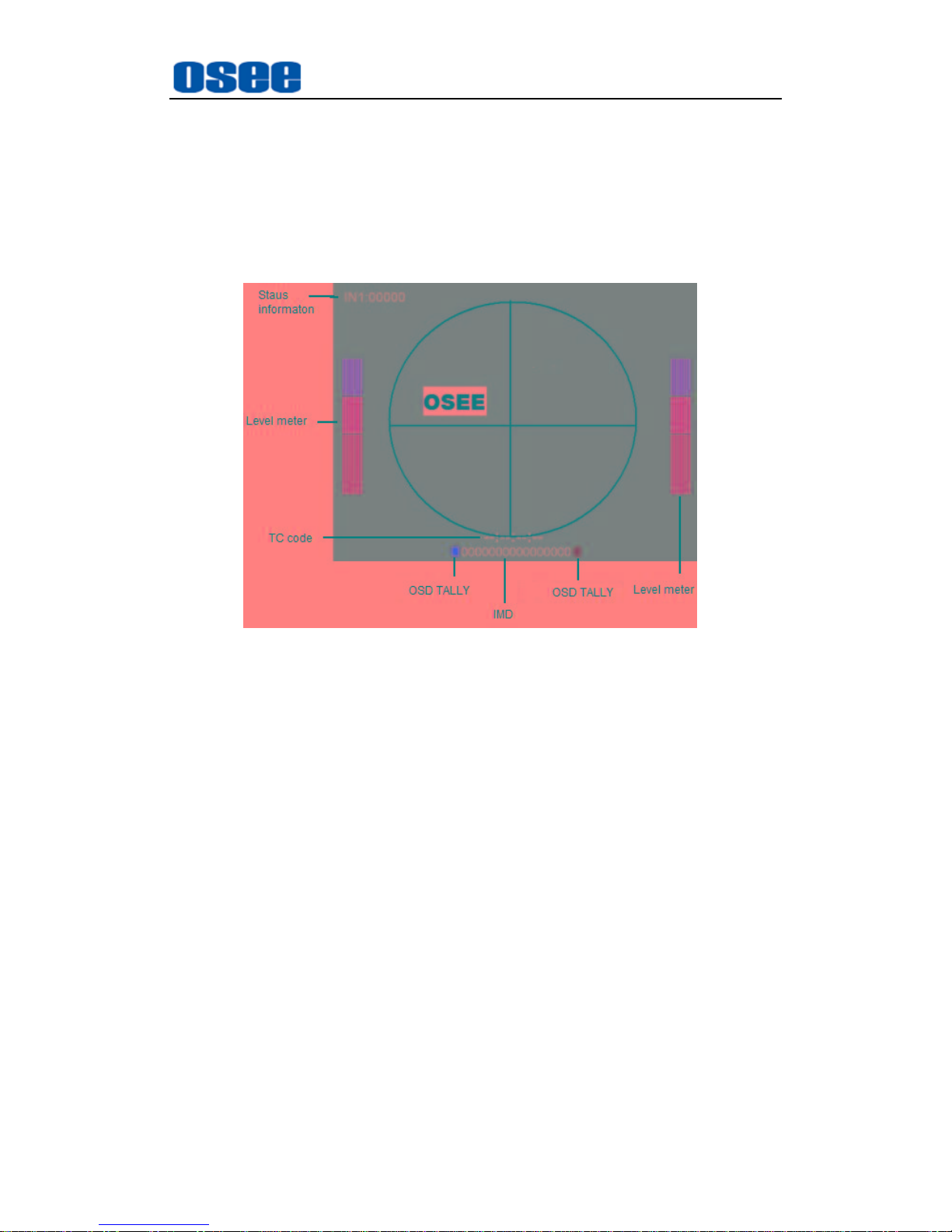
This chapter describes the features of MVM-200 monitor. The features of
MVM-200 monitor are as shown in Figure 4-1 after installed and powered on:
Figure 4-1 Features of MVM-200 Monitor
1. Status Information
It is displayed in the top left corner of each display window on the
screen, and includes the input channel and signal format.
2. Audio Meter
It is displayed for audio monitoring. You can set its parameters in
AUDIO CONFIG menu. It could be semi-transparent displayed which
will reduce the impact for the image.
3. Waveform and Vector
This is effective only for SDI signal. The waveform and vector of the
input signal are configurable in the OSD CONFIG Menu.
4. Area Marker/Safe Marker/Center Marker
It is used to mark different area or position of the image, and there are
various marker, including Area Marker, Safe Marker, Center Marker.
You can set whether to display it or not and their displaying mode in
MARKER menu.
Page 20
MVM Monitor Features
14
5.
Timecode
It is displayed at the bottom of the image, the format is HH:MM:SS:FF,
if there is no timecode available, the monitor will display --:--:--:--. You
can set its parameters in OSD CONFIG menu.
6. OSD TALLY
It is displayed OSD TALLY rectangle at the both sides of IMD bar, in
the bottom of each display window, and the color could be changed
according to the designated color (red, green, yellow, white). You can
set its parameters in OSD CONFIG menu.
7. IMD
The IMD text displays at the bottom of the screen, the length can’t
exceed 16 characters, and you can choose letter, number or other
character for it. You can set its parameters in OSD CONFIG menu.
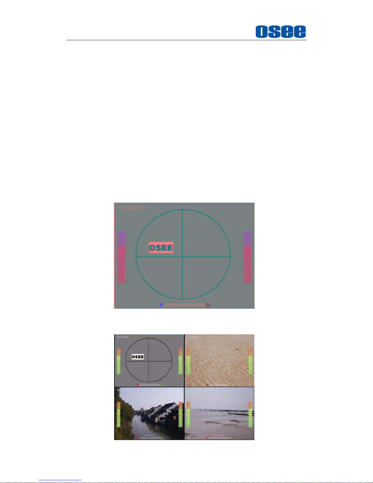
There are several display modes for MVM-200 display: Single-screen,
Four equal screens, and One-big and with Three-small Screen.
Figure 4-2 Single-screen, full 16-channel audio meter
Page 21
MVM Monitor Features
15
Figure 4-3 Four-screen, full 16-channel audio meter
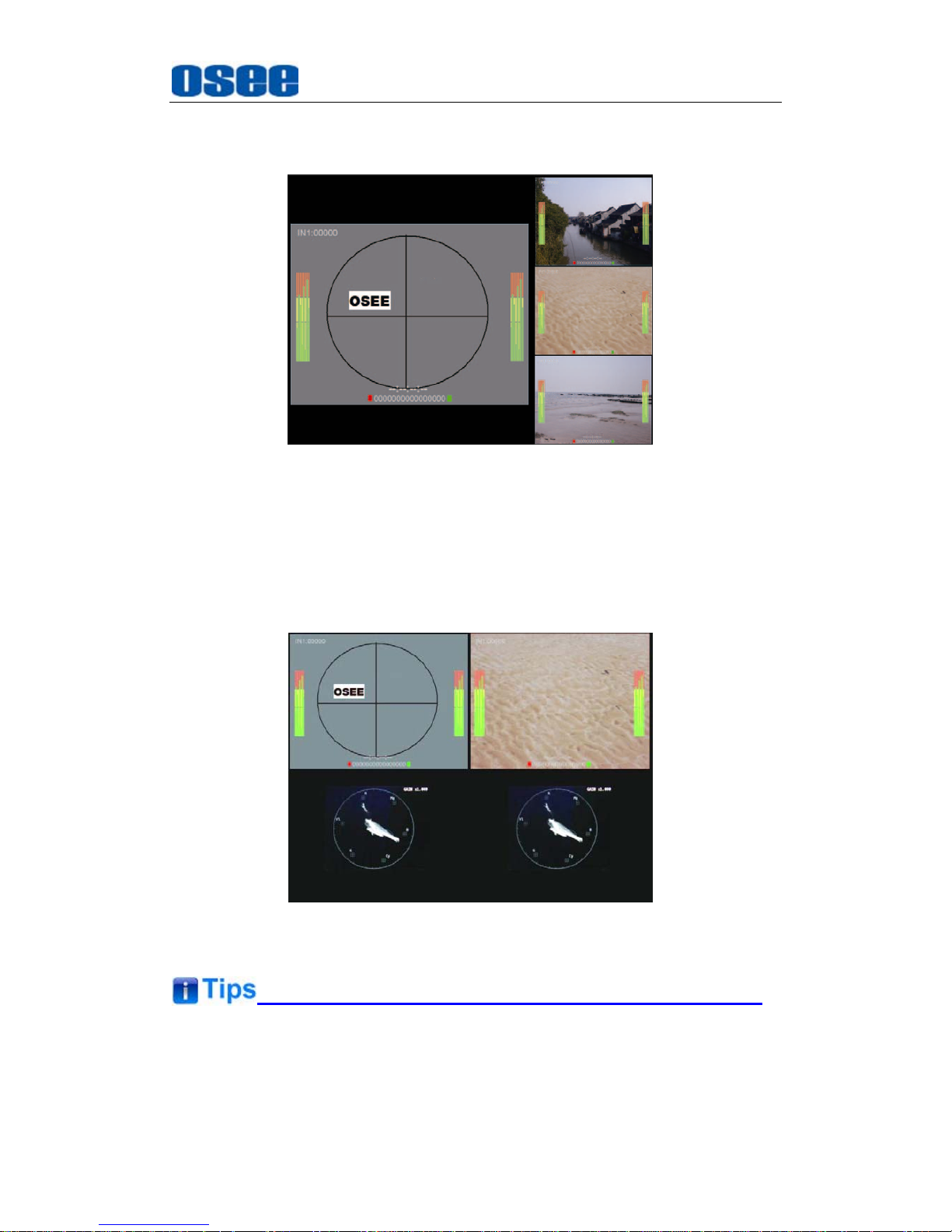
Figure 4-4 One-big and With Three-small Screen, Full 16-channel
Audio Meter
Waveform and vector display: It displays only for CH1 and CH3 in the screen.
Each channel is corresponding to a display window. You can see the
Waveform and vector of CH1 is displayed in No.2 Window, and the Waveform
and vector of CH3 is displayed in No.4 Window.
Figure 4-5 Waveform and Vector Display
The
Status Information
displays at the top left corner of the each window,
it usually displays as the following situations:
Page 22
MVM Monitor Features
16
"UNKNOW” appears if an unsupported signal is input.
“NO SIGNAL” appears if no signal is input.
The signal is normal, for example: 1080i59.94, NTSC, 1280X1024,
etc.
4.1 Front Panel Features
It will introduce the arrangement and the operations of the buttons in front of
the panel in the following.
4.1.1 Arrangement of Front Panel
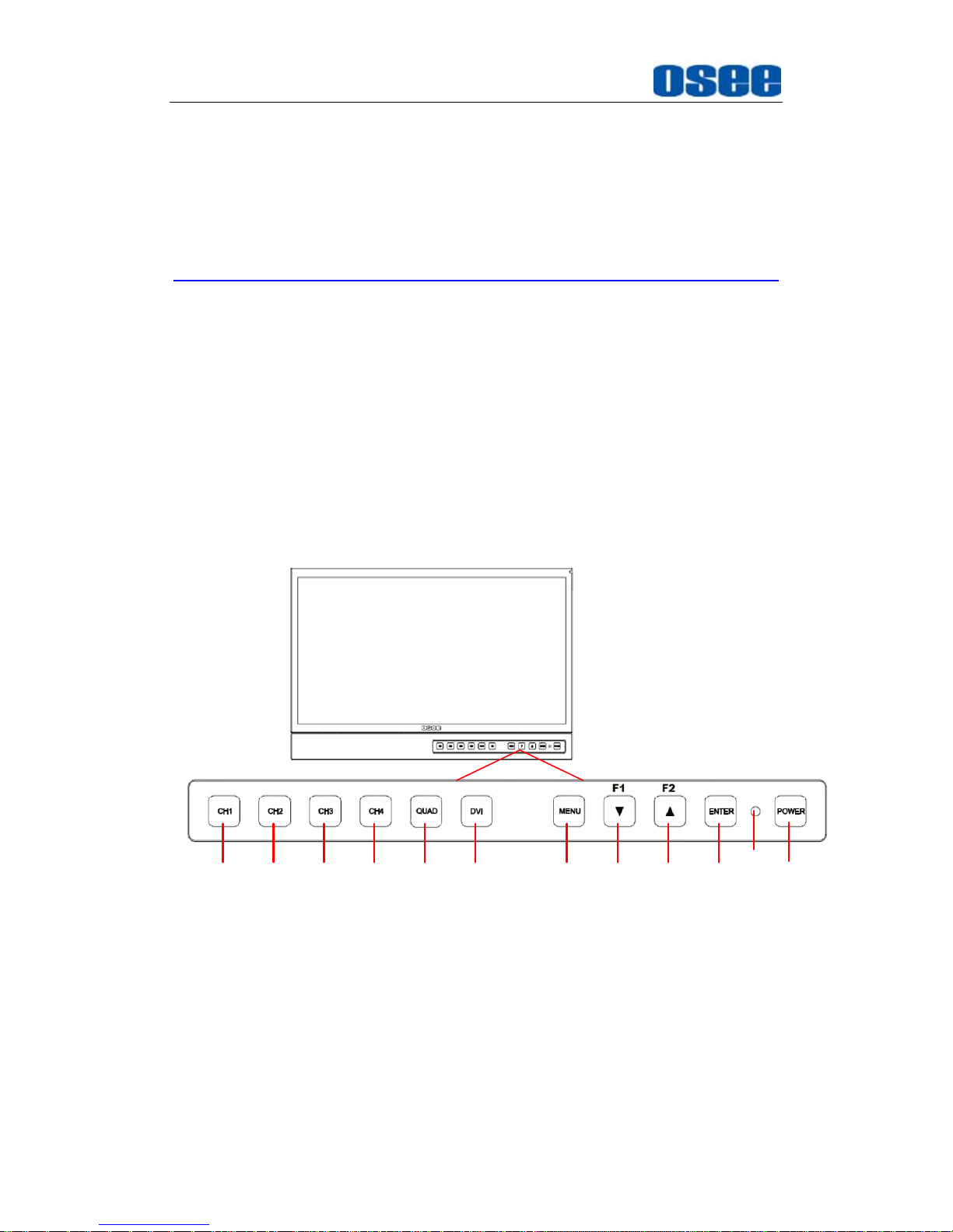
There are a series of buttons at the bottom of the screen, and these
buttons are used to control the screen menu items.
123456 78910 11
12
Figure 4.1-1 the Buttons in Front Panel
As shown in Figure 4.1-1, these buttons are as follows:
1. CH1
2. CH2
3. CH3
4. CH4
Page 23
MVM Monitor Features
17
5.
QUAD
6. DVI
7. MENU
8. F1/DOWN
9. F2/UP
10. ENTER
11. POWER
12. POWER indicator
The functionality of the control buttons on the top of the monitor is as the
same as the extra control buttons.
4.1.2 Operation of Front Panel
The functionality and usage of the buttons are as follows:
1. CH1
It is used to switch to the full screen of CH1, or select the signal from IN1
input interface.
Operation
Full screen of CH1: Press this button to switch from quad split
screen display to
CH1
full screen display.
Select CH1: when in quad split screen display mode, press
MENU
button to display the main menu in the center of the screen, then
press
CH1
button to switch to the
IN1
signal, and it will show the
CH1 information in the menu list. The current selected window will
be highlighted at the outline of the display window.
2. CH2
It is used to switch to the full screen of CH2, or select the signal from IN2
input interface. The operation is as the same as CH1's.
3. CH3
It is used to switch to the full screen of CH3, or select the signal from IN3
input interface. The operation is as the same as CH1's.
4. CH4
Page 24
MVM Monitor Features
18
It is used to switch to the full screen of CH4, or select the signal from IN4
input interface. The operation is as the same as CH1's.
5. QUAD
This button is used to switch to display quad split windows, including four
uniform size screens display, one big with three small screens display.
Refer to “4.1.3 Display Mode” for details.
6. DVI
This button is used to switch the signal source for CH1 between HDMI
and IN1.
7. MENU
It is used to activate the Main menu. Press this button to do some
operations with the Main menu, it includes the following operations:
Display the Main menu
Back to the higher level menu
Quit the Main menu
Refer to “5.2 Menu Settings” for detail about the main menu operations.
After you have loaded the function menu list, it will be closed automatically
if you do nothing operation with it in 5s.
If the value related to the function button can’t be modified, the value
shows in highlight yellow.
8. F1/DOWN
This button is used to be a function button or an adjustable button. The
function can be set via the USER CONFIG menu.
Function button:
Press F1 to display the function menu list at the left
bottom corner of the screen. Toggle F1 button to change the value
related to this function
Adjustable button
: It is
DOWN(▼)
button when working with
MENU
.
Toggle this button to select the next item or decrease the number.
Use
FUNCTION KEY
menu to assign F1, F2. You can assign the function
from among: H/V DELAY, ASPECT, SCAN, MONO, BLUE ONLY, NATIVE,
Page 25
MVM Monitor Features
19
WAVEFORM, AUD METER, MARKER, NONE. Refer to "5.1.6 USER
CONFIG Menu" for the details.
9. F2/UP
This button is used to be a function button or an adjustable button. The
function can be set via the USER CONFIG menu.
Function button:
Press F2 to display the function menu list at the left
bottom corner of the screen. Toggle F2 button to change the value
related to this function
Adjustable button
: It is
UP(▲)
button when working with
MENU
.
Toggle this button to select the next item or decrease the number.
10. ENTER
This button can achieve the following two situations:
Work with the Main MENU
: when working with the Main menu,
ENTER button achieve the following functions:
Enter into the next level menu: press
ENTER
button, you will enter
into the menu item as this relationship: the Main menu list
sub-menu list sub-menu value list, the current editable object is
in yellow control icon;
Confirm the value selection: press
ENTER
button to confirm the
value selection.
Adjust Menu:
when not displaying the Main menu, press
ENTER
button to display the adjust menu list, as shown in Figure 4.1-2,
toggle among these menu items: VOLUME, BRIGHTNESS,
CONTRAST, CHROMA.
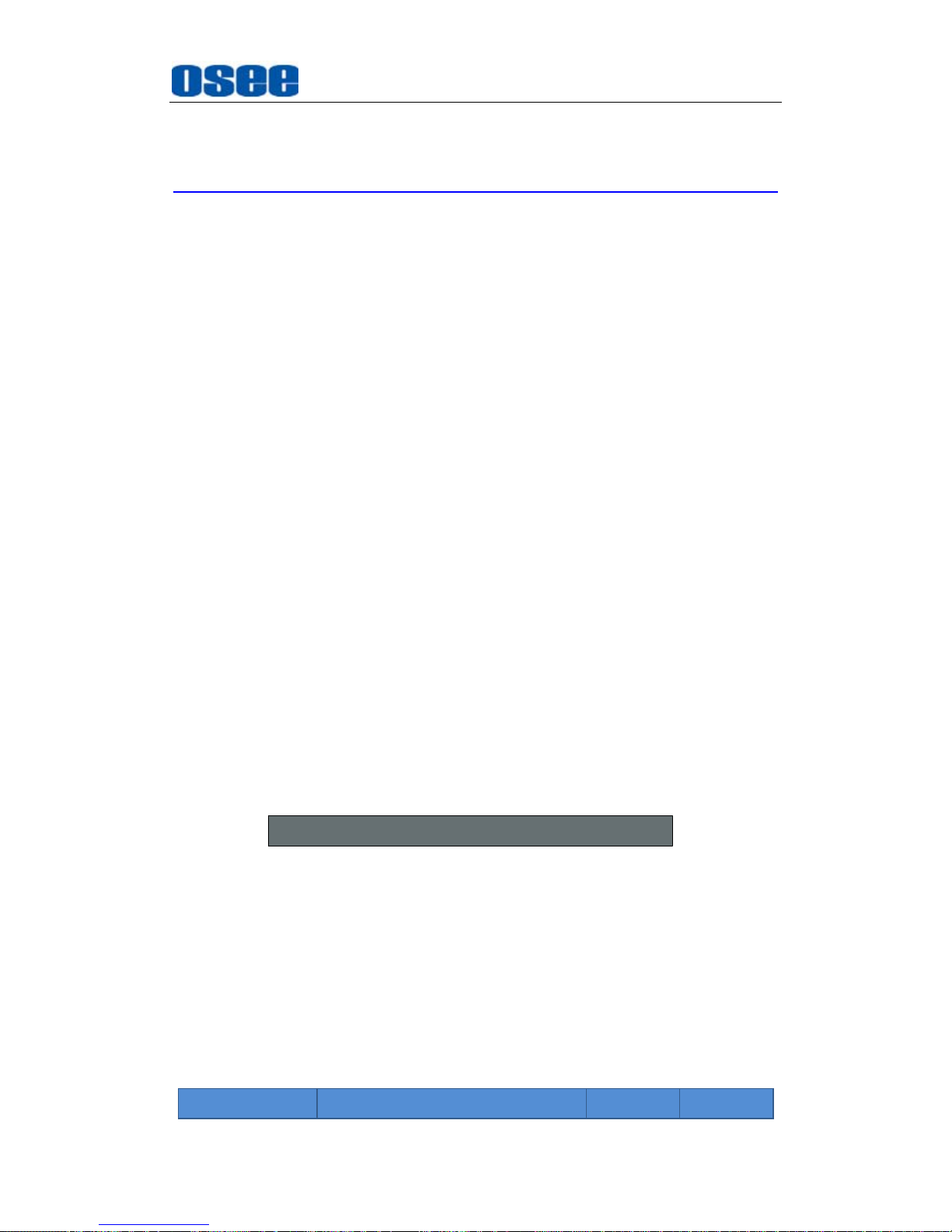
BRIGHTNESS 50
Figure 4.1-2 Adjust Menu List
After displaying the Adjust menu, press UP or
DOWN
button to adjust
the menu value, and then press
ENTER
button to confirm the value
selection.
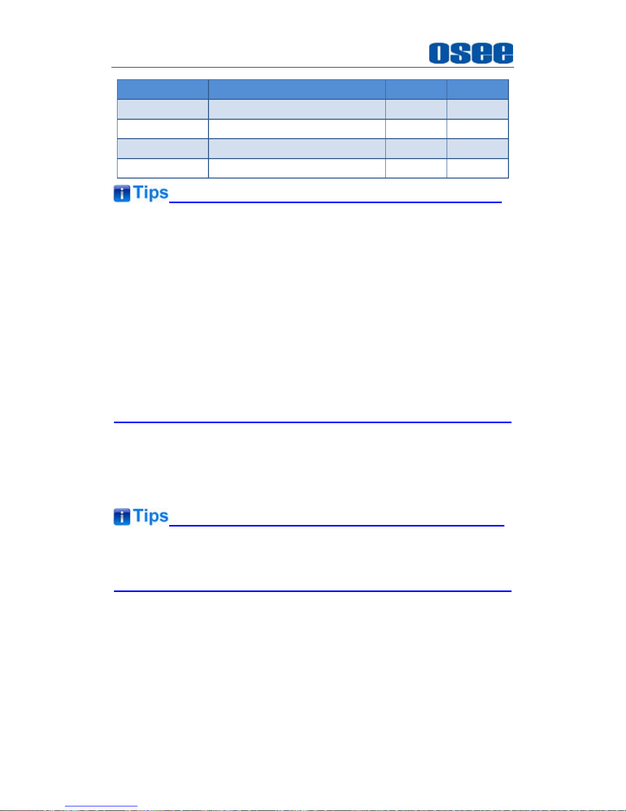
The relationship of the menu items and their range is shown in Table
4.1-1:
Table 4.1-1 The Description of Adjust Menu Items
Adjust Menu Description Range Default
Page 26
MVM Monitor Features
20
Adjust Menu Description Range Default
VOLUME Adjust the volume 0~30dB 15
BRIGHTNESS Adjust the image brightness 0~100 50
CONTRAST Adjust the image contrast 0~100 50
CHROMA Adjust the image monochroma 0~100 50
Set these parameter values in the following position: BRIGHTNESS,
CONTRAST, CHROMA.
In Adjust Menu List on screen when pressing Enter key.
In Adjust menu of network control page.
After you have loaded the adjust menu list, it will be closed automatically if
you do nothing operation with it in 5s.
The main menu, the adjust menu, the function menu and the input signal
selection list of a screen may not be shown all simultaneously.
11. Power
Used to power on or standby, and the light in the button will indicate the
status of the power. If the light is green, the monitor is powered on, if the
light is flashing, the monitor is standby.
When the device is standby, cut off the power and restart the device, the
status of the device will be normal but not standby.
4.1.3 Display Mode
This device provides several display modes: Single screen, QUAD split
screen.
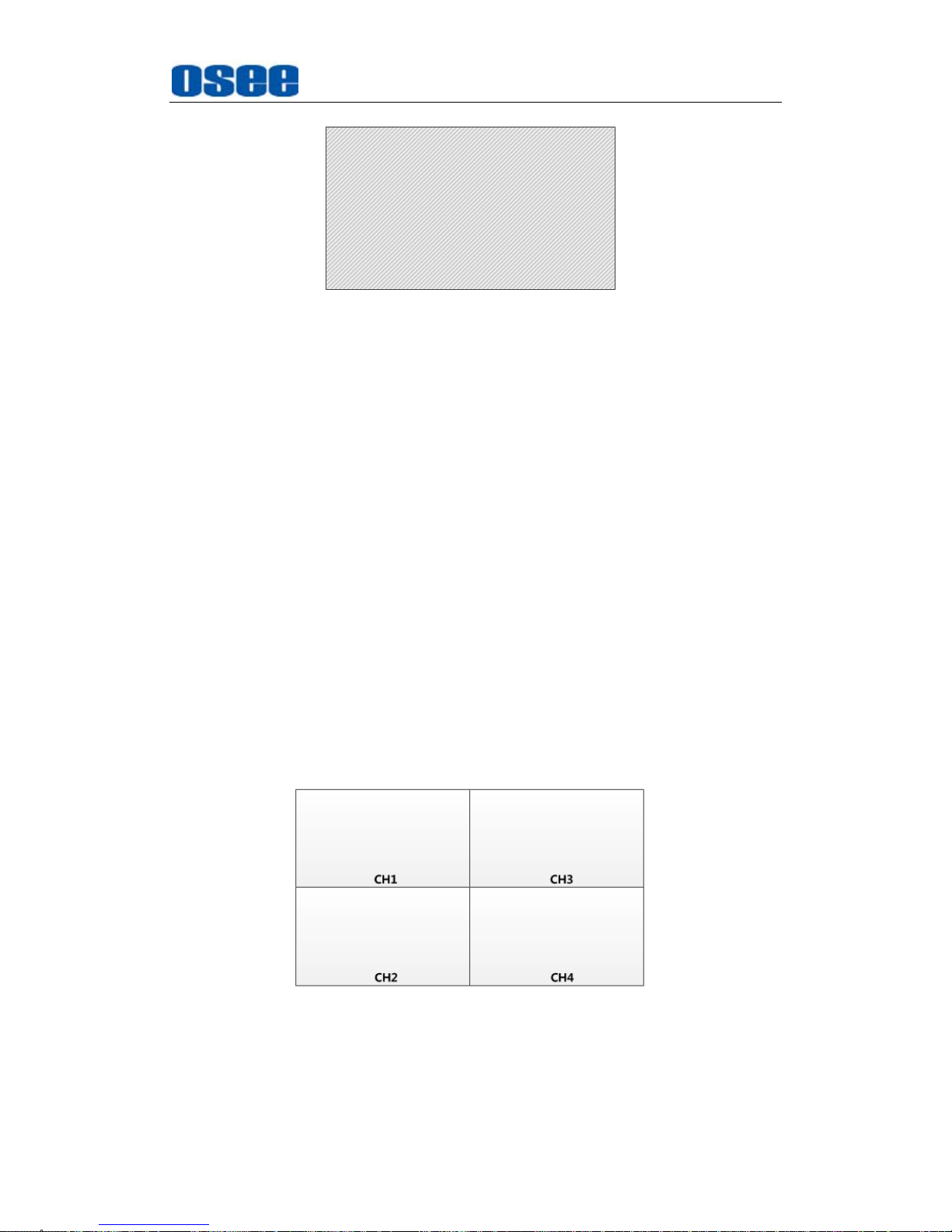
1. SINGLE: full screen display mode
There is only one picture for one signal source on the whole screen in
SINGLE mode, as shown in Figure 4.1-3:
Page 27
MVM Monitor Features
21
SINGLEMODE
CH1
Figure 4.1-3 SINGLE Mode
Switch to SINGLE MODE: Press
CH1, CH2, CH3 or CH4
to display
the corresponding input signal on the full screen.
Signal Source Selection: Press
CH2, CH3, CH4
button, it will display
the corresponding signal source to
IN2, IN3, IN4
. If press
CH1
button,
it will display to signal source
IN1
by default, then, press
DVI
button
to switch between
IN1
and
HDMI
(coming from HDMI IN interface).
That is, the HDMI input could only be displayed in CH1 or CH1’s full
screen.
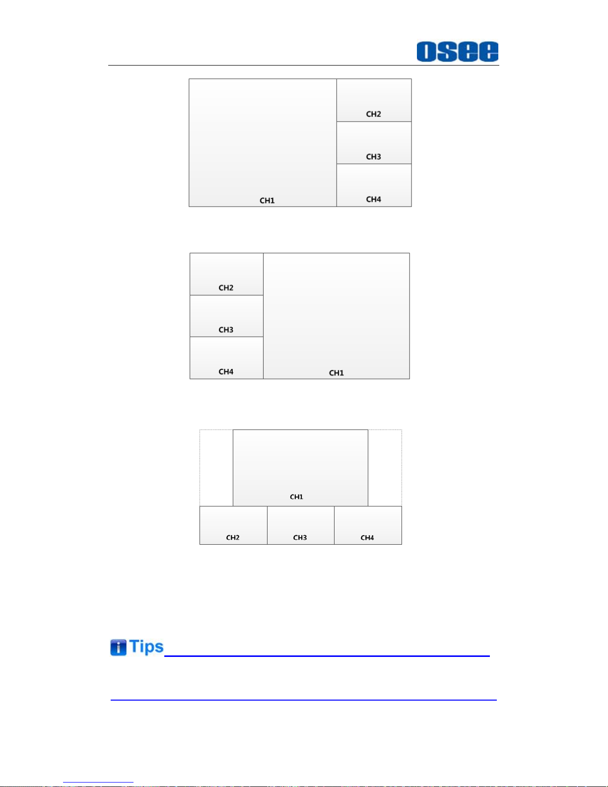
2. QUAD: QUAD split display mode
The whole screen is divided into four windows in QUAD mode, there are
two kinds of layouts: four uniform size screens(LAYOUT1) and one big
with three small screens. The latter including one big left with three right
small(LAYOUT2), one big right with three left small(LAYOUT3), one big
top with three bottom small(LAYOUT4).
Press
QUAD
button to switch among these four modes cyclically in
sequence, and you can see a prompt at the left corner of the screen to
show the layout character.
Figure 4.1-4 LAYOUT1-Four Uniform Size Screens
One big with three small screens display: one big left with three right
small, one big right with three left small, one big top with three bottom
small, as shown in Figure 4.1-5, Figure 4.1-6, Figure 4.1-7:
Page 28
MVM Monitor Features
22
Figure 4.1-5 LAYOUT2-One Big Left with Three Right Small
Figure 4.1-6 LAYOUT3-One Big Right with Three Left Small
Figure 4.1-7 LAYOUT4-One Big Top with Three Bottom Small
The relationship between the display window and signal source channel is
one to one correspondence, and the position of each split window in the
above display modes is settled.
The signal source of CH1 can only be IN1 or HDMI.
Page 29
MVM Monitor Features
23
4.2 Rear Panel Features
It will introduce the arrangement and the operations of the interfaces in rear
of the panel in the following.
4.2.1 Arrangement of Rear Panel
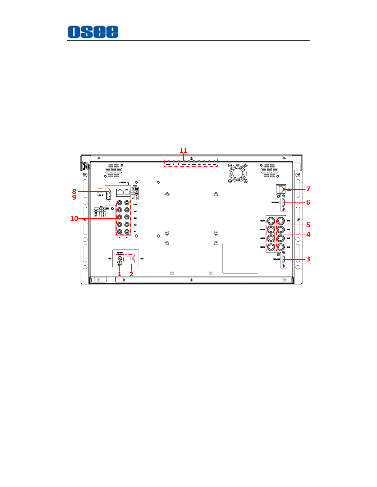
Take MVM-200 for example, as shown in Figure 4.2-1, there are various
input and output interfaces at the rear panel of MVM-200 monitor.
Figure 4.2-1 The Rear Panel of MVM-200 Monitor
The interfaces numbered from 1 to 8 in red dotted rectangle are
described as follows:
1. Power Input
2. Power Switch
3. HDMI Input Interface
4. Video Input Interface: IN1, IN2, IN3, IN4
5. Video Output Interface: OUT1, OUT2, OUT3, OUT4
6. HDMI Output Interface
7. Ethernet
8. GPI
Page 30
MVM Monitor Features
24
9.
RS485
10. Audio Input/Output Interface
11. Top Control Buttons
4.2.2 Operations of Rear Panel
The details of these interfaces at the rear panel are described as follows:
1. Power Input
It provides one power input interface, the specification is DC18~20V. If
the power indicator is in green, the monitor is powered on, and if the
power indicator is off, the monitor is powered off.
Only use the power cord specified by the manufacture for your safety!
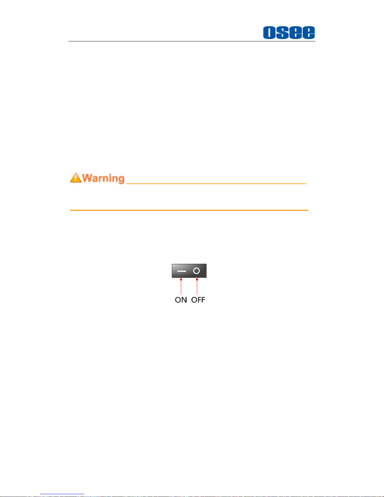
2. Power Switch
It provides one power switch to switch on or switch off. As shown in
Figure 4.2-2, push the button to the direction “-” to switch on the power,
or push the button to the direction “” to switch off the power.
Figure 4.2-2 Power Switch
3. HDMI Input Interface
It provides one HDMI input interface, HDMI Type-A connector with a
fastener.
4. Video Input Interface (BNC)
It provides four video input interfaces, labeled as IN1, IN2, IN3, IN4.
These inputs are adaptable for CVBS, SD/HD/3G-SDI(with embedded
audio). The IN1 is multiplexed with HDMI input for CH1.
5. Video Output Interface (BNC)
It provides four video output interfaces, labeled as OUT1, OUT2,
OUT3, OUT4. Loop out, corresponding with IN1, IN2, IN3, IN4.
Page 31
MVM Monitor Features
25
6.
HDMI Output Interface
It provides one HDMI output interface, HDMI Type-A connector with a
fastener. It outputs the content of the current display on screen, that is,
the screen could be a single image, or a group of four images.
7. Ethernet (RJ-45)
It provides one 10/100M Ethernet connector. It is used to connect with
a computer to modify the network settings.
8. GPI(DB9)
It is used to control Tally light.
The relationship of the pins of GPI interface and its channel value is
shown in Table 4.2-1.
Table 4.2-1 The Relationship of GPI Pins and Channel Values
Tally Light Color RED GREEN GND
IN1 Pin 1 Pin 6
Pin 5
IN2 Pin 2 Pin 7
IN3 Pin 3 Pin 8
IN 4 Pin 4 Pin 9
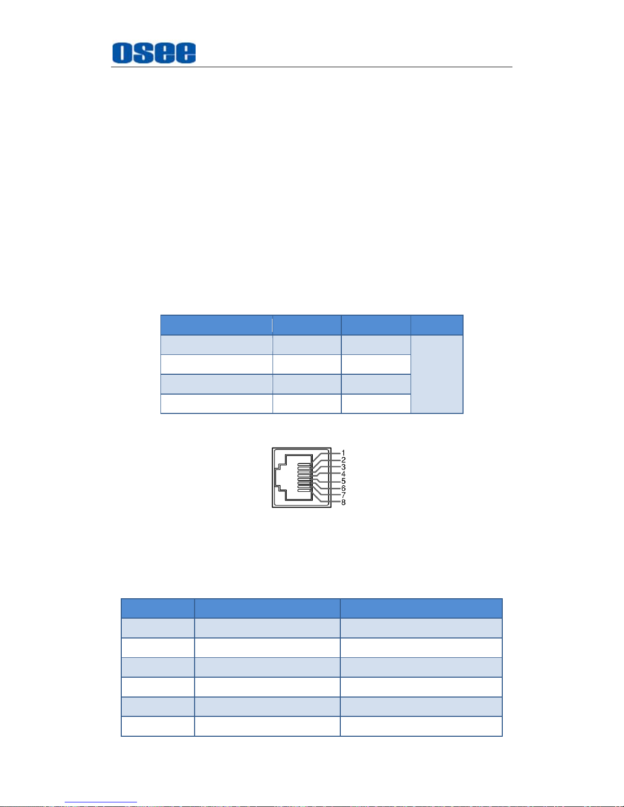
9. IN/ OUT RS485 Interface (RJ-45)
Support for dynamic IMD and updating the new firmware.
The Comparison of Pins and Input/output connectors for RS485 is
shown as in Table 4.2-2:
Table 4.2-2 Input/output connectors for RS485
PIN No. RS485 IN Terminal Signal RS485 OUT Terminal Signal
1,2 GND GND
3 Tx- Tx-
4 Rx+ Rx+
5 Rx- Rx-
6 Tx+ Tx+
7,8 NC NC
Page 32
MVM Monitor Features
26
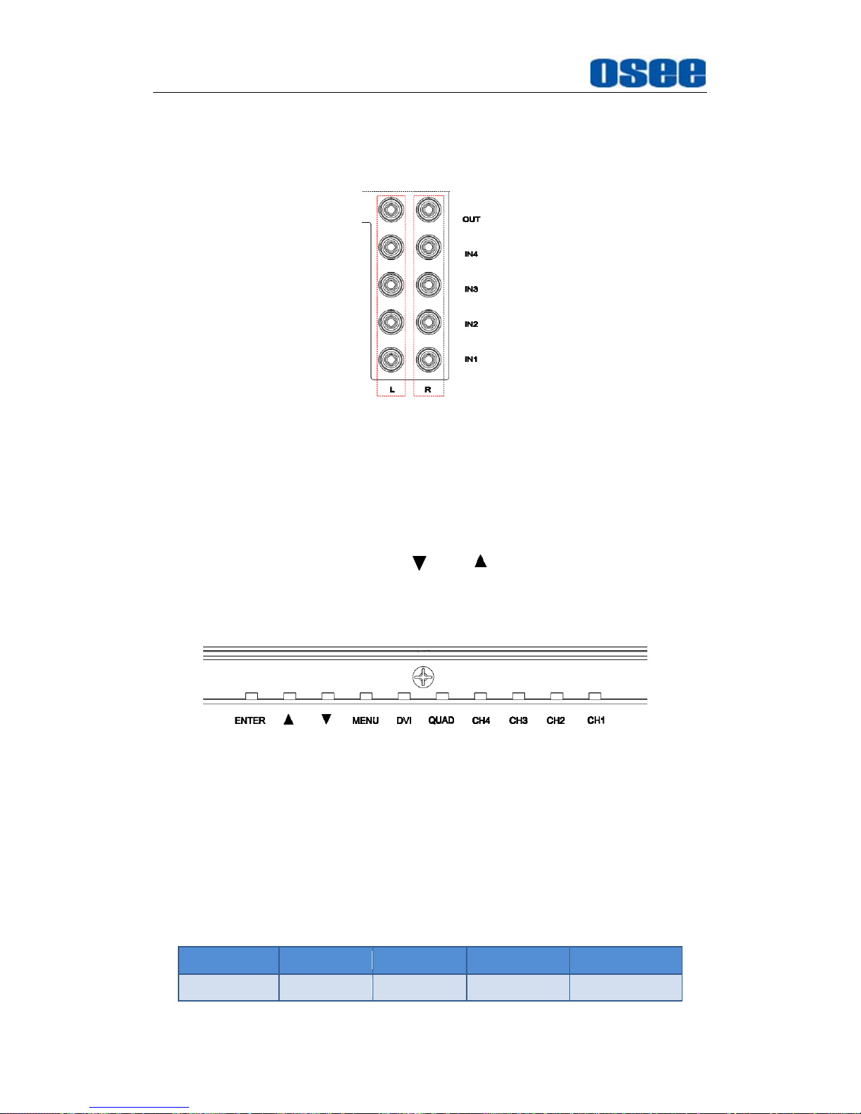
10.
Audio Input/Output interface
It provides four pairs of audio input interfaces, and one pair of audio
output interfaces, RCA connector.
Figure 4.2-3 Audio Input/Output interface
11. Top Control Buttons
It provides a bar of control buttons at the top of the monitor, the
sequence of these buttons from right to left are CH1, CH2, CH3, CH4,
QUAD, DVI, MENU, DOWN( ), UP( ), ENTER, facing at the rear
panel of the monitor. The functionality of these buttons is the same as
the extra control buttons, no more description here.
Figure 4.2-4 Top Control Buttons
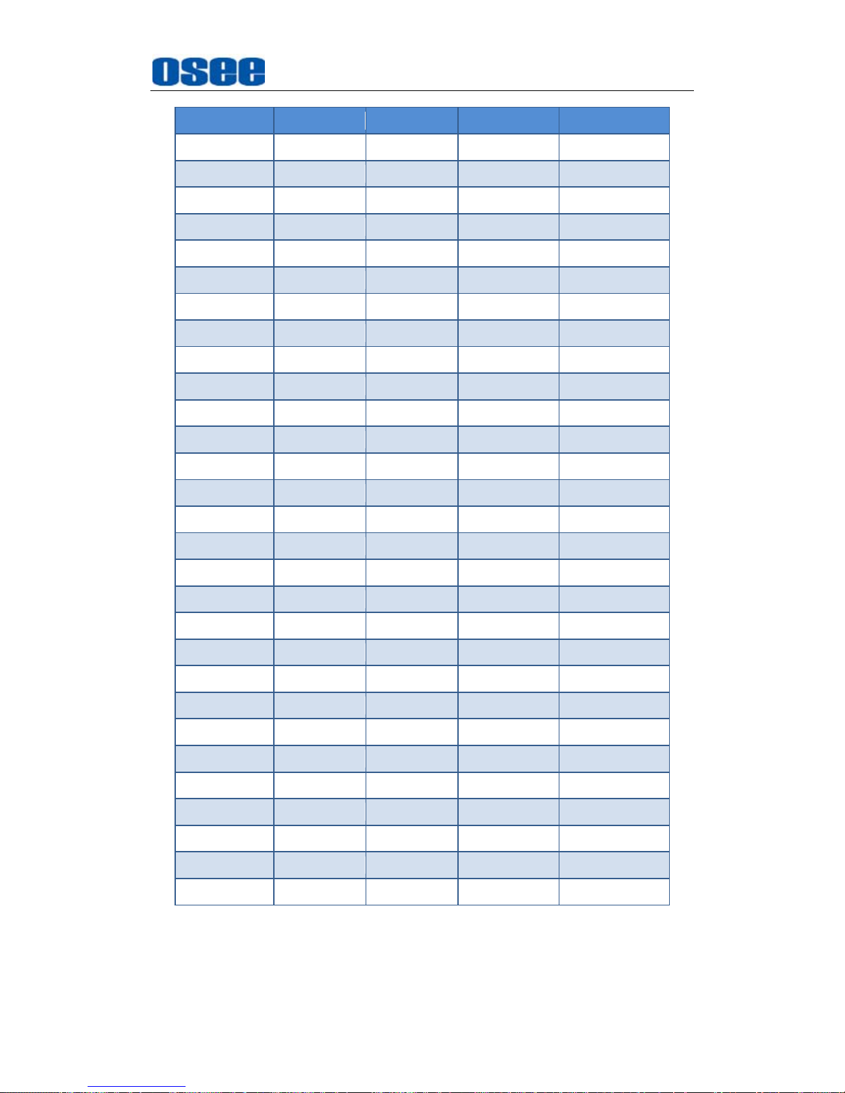
4.3 Supported Signal Format
The supported signal format for this device is as shown in Table 4.3-1:
Table 4.3-1 Supported Signal Format
SDI Video HDMI DVI
NTSC YES
Page 33
MVM Monitor Features
27
SDI Video HDMI DVI
PAL YES
SECAM YES
NTCS-4.43 YES
PAL-M YES
480I60 YES YES
576I50 YES YES
480P60 YES
576P50 YES
720P24 YES
720P25 YES
720P30 YES
720P50 YES YES
720P60 YES YES
1035I60 YES YES
1080I60 YES YES
1080I50 YES YES
1080P24 YES YES
1080P25 YES YES
1080P30 YES YES
1080P50 YES YES
1080P60 YES YES
1080SF24 YES
VGA YES
SVGA YES
XGA YES
SXGA YES
UXGA YES
WVGA YES
WXGA YES
Page 34

28
Page 35
Functionality of the Main Menu
29
Chapter 5 Functionality of the Main Menu
This chapter describes the structure and functionality of the main menu, and
introduces how to modify and customize the menu settings.
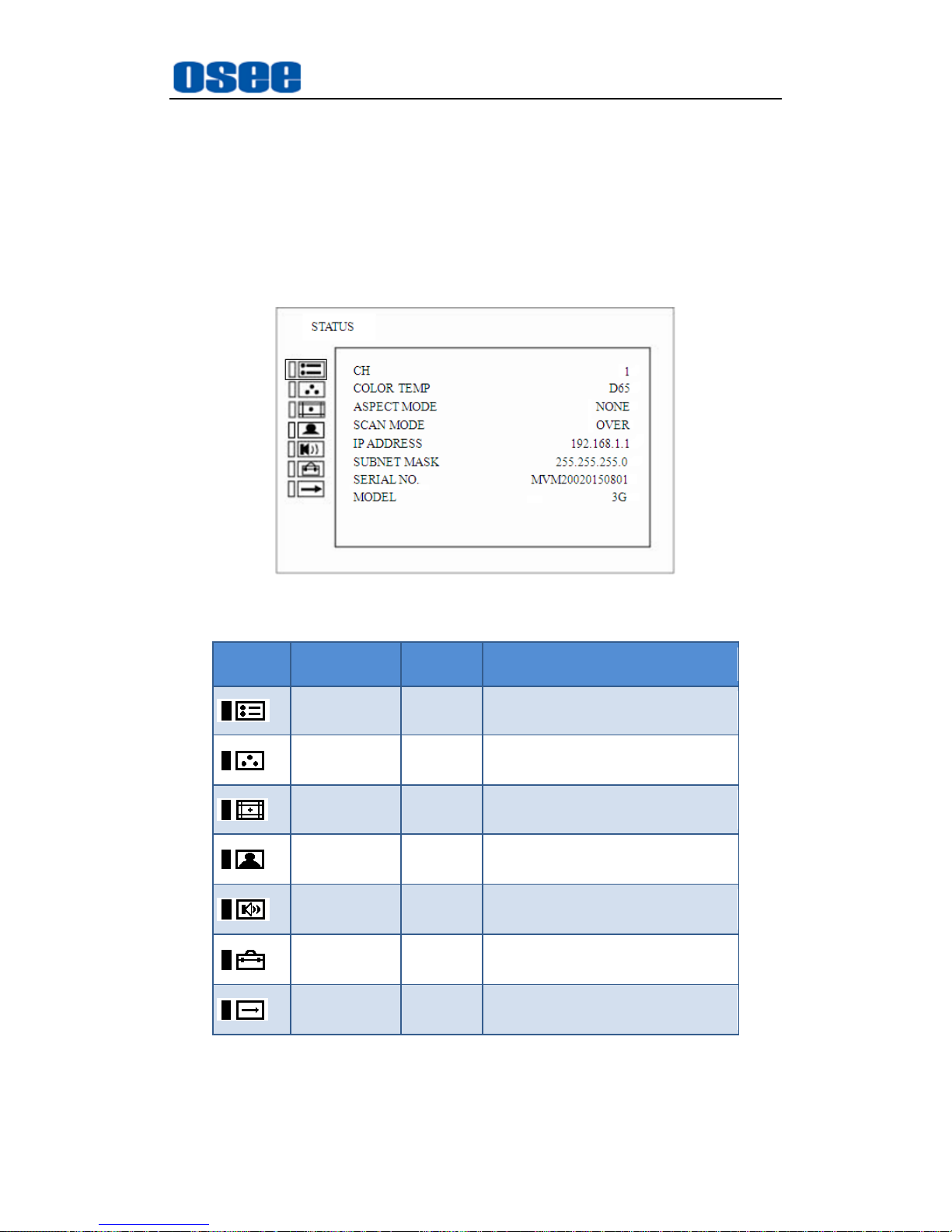
The main menu includes the following menu items, as shown in Figure5-1.
Figure 5-1 Main Menu
Icon Menu Item Pages Description
STATUS 1 Status information
COLOR
TEMP
1 Color temperature information
MARKER 1 Marker information
ALRAM
CONFIG
1 Alarm information
AUDIO
CONFIG
1 Audio information
USER
CONFIG
1 User config information
OSD
CONFIG
2 OSD information
Page 36
Functionality of the Main Menu
30
5.1 Main Menu
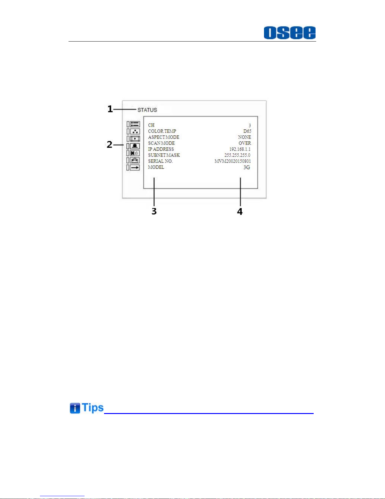
Press the MENU button, the main menu is displayed at the center of the
screen, as shown in Figure 5.1-1:
Figure 5.1-1 the Structure of the Main Menu
The menu interface is divided into three parts:
1. Menu Name
It displays the menu name of the current selected menu in menu list.
2. Main Menu List
It contains the menu list. Press UP or DOWN button to select the
corresponding menu item.
3. Sub-menu list
It lists the sub-menus, press MENU, UP, DOWN, Enter button to select
the sub-menu item.
4. Sub-menu value list
It lists the sub-menus value of the current select sub-menu, press UP,
DOWN and Enter button to modify the value of the sub-menu. Refer to
“5.2 Menu Settings” for details.
There is a yellow control icon when you select the menu or its value.
The sub-menu item is selected when the control icon which is in yellow
Page 37
Functionality of the Main Menu
31
highlight is at the back of the item name.
The sub-menu item value is editable when the control icon which is in
yellow highlight is at the back of the item value.
The following will introduce the contents and functionality of these sub-menu
items in sorts.
5.1.1 STATUS Menu
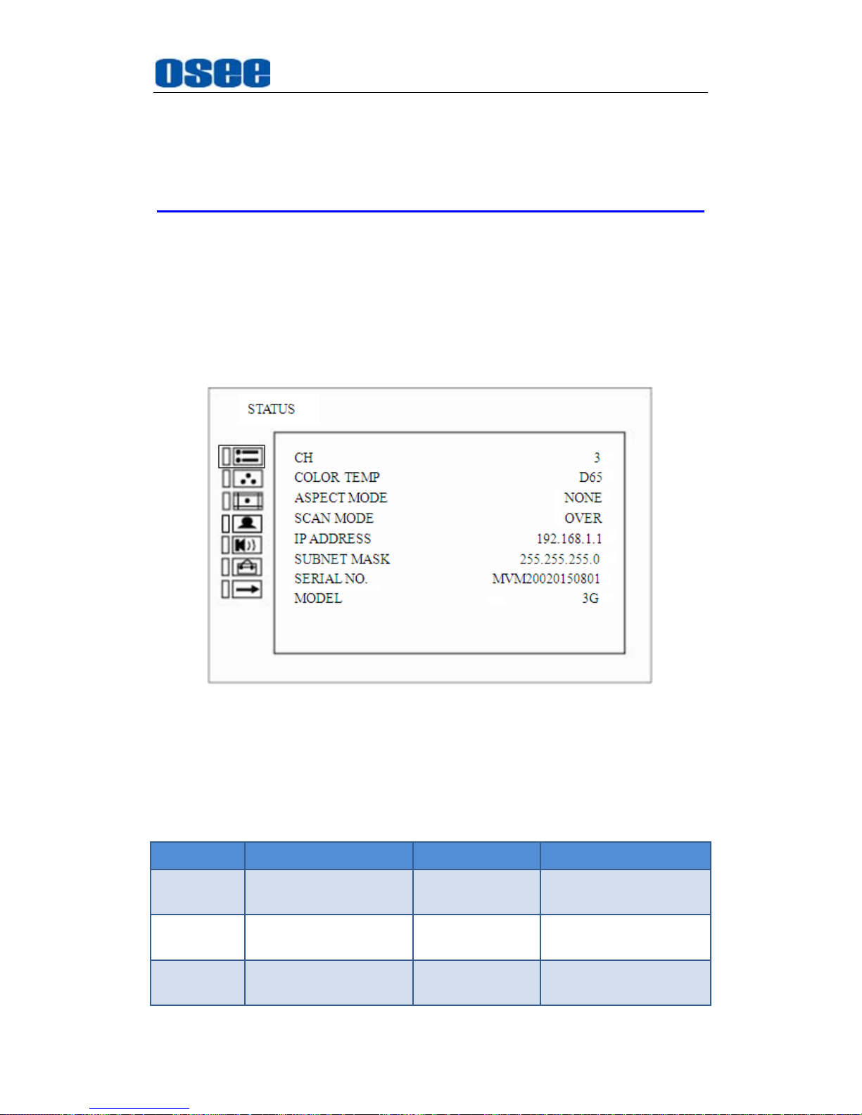
The STATUS menu items are used to describe the current status
information of the monitor, the menu items are as shown in Figure 5.1-2:
Figure 5.1-2 STATUS Menu
The relationship of Items, Default Value, Domain Range and Description
of the sub-item is shown in Table 5.1-1:
Table 5.1-1 The Description of STATUS Menu Items
Items Default Value Domain Range Description
CH 3
--
Show the Input
channel number.
COLOR
TEMP
D65 --
Show the color
temperature.
ASPECT
MODE
16:9 --
Show the screen
Aspect Ratio.
Page 38
Functionality of the Main Menu
32
Items Default Value Domain Range Description
SCAN
MODE
NORMAL
--
Show the scan mode.
IP
ADDRESS
192.168.1.86
--
Show the IP address.
SUBNET
MASK
255.255.255.0 --
Show the subnet
mask.
SERIAL
NUMBER
MVM2002015010801 --
Show the serial
number.
MODEL 3G --
Show the production
model.
The sub-menu values in
STATUS
menu can’t be modified, they are
displayed the actual status of the monitor.
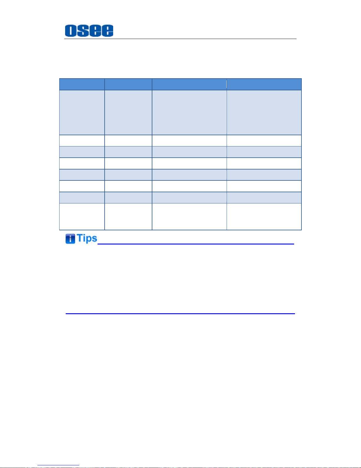
5.1.2 COLOR TEMP Menu
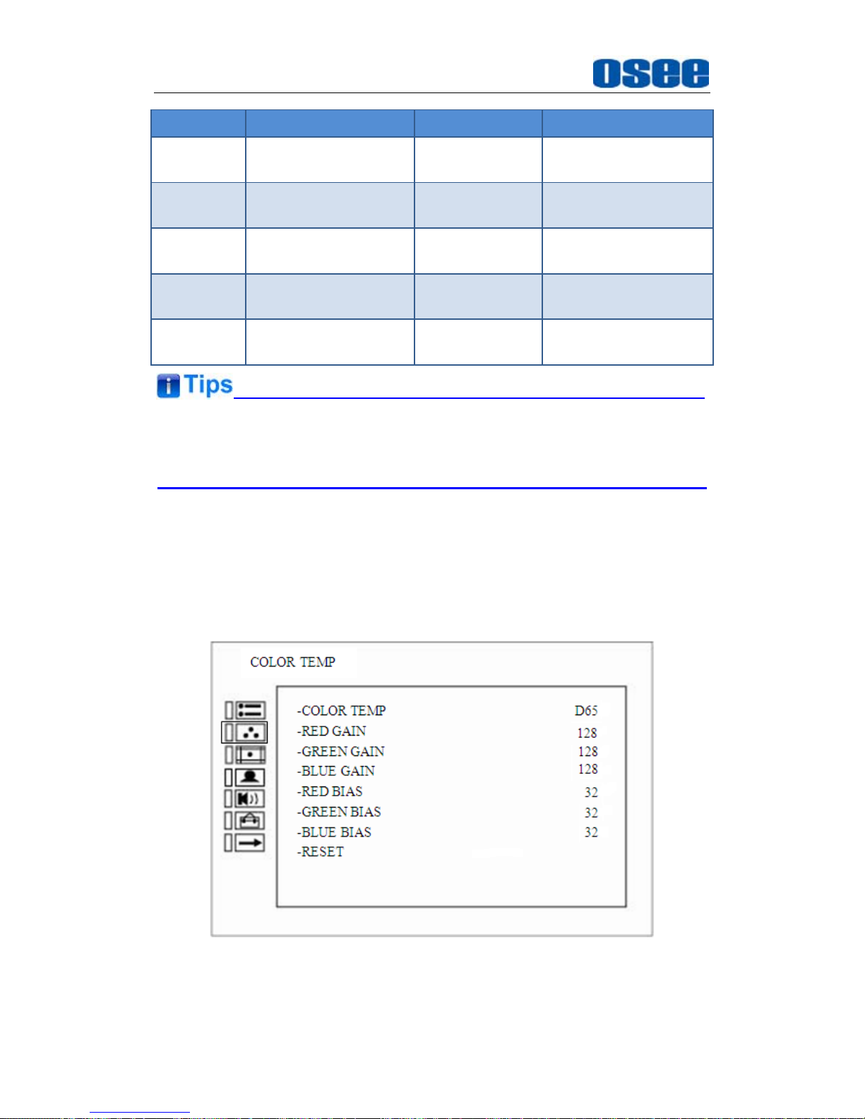
The COLOR TEMP menu items are used to adjust the color temperature
parameters and the color balance, the menu items are as shown in Figure
5.1-3:
Figure 5.1-3 COLOR TEMP Menu
The relationship of Items, Default Value, Domain Range and Description
Page 39
Functionality of the Main Menu
33
of the sub-item is shown in Table 5.1-2:
Table 5.1-2 The Description of COLOR TEMP Menu Items
Items Default Value Domain Range Description
COLOR
TEMP
D65
USER: Customized
by user
D56:5600K
D65:6500K
D93:9300K
Set color temperature
RED GAIN 128 0~256 Adjust the Red Gain
GREEN GAIN 128 0~256 Adjust the Green Gain
BLUE GAIN 128 0~256 Adjust the Blue Gain
RED BIAS 32 0~64 Adjust the Red Offset
GREEN BIAS 32 0~64 Adjust the Green Offset
BLUE BIAS 32 0~64 Adjust the Blue Offset
RESET -- --
Reset the Gain and
Offset values to the
product originals
The items about RED/GREEN/BLUE GAIN and BIAS are available only in
USER mode. If the COLOR TEMP is set to
USER
with customized settings,
you can select the menu item
COLOR TEMP RESET
command to
restore product originals for Gains and Offsets, and press
ENTER
button to
confirm the reset operation.
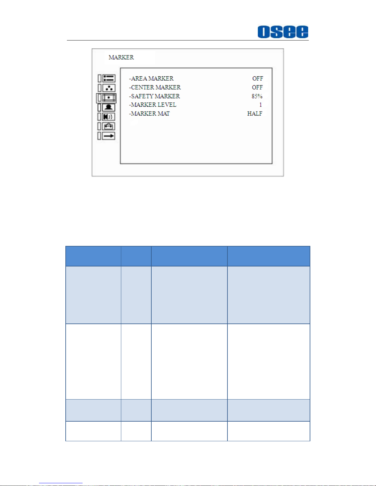
5.1.3 MARKER Menu
The MARKER menu items are used to adjust the marker parameters, the
menu items are as shown in Figure 5.1-4:
Page 40
Functionality of the Main Menu
34
Figure 5.1-4 MARKER Menu
The relationship of Items, Default Value, Domain Range and Description
of the sub-item is shown in Table 5.1-3:
Table 5.1-3 The Description of MARKER Menu Items
Items
Default
Value
Domain Range Description
MARKER OFF OFF/ON
Set whether to show all of
the markers.
It is the main switch for
area marker, center
marker and safety
marker.
AREA MARKER OFF
OFF: close area
marker
4:3
16:9
15:9
14:9
13:9
1.85:1
2.35:1
Select the area marker
aspect ratio according to
the display aspect ratio.
CENTER
MARKER
OFF OFF/ON
Set whether to show the
center marker
SAFETY
MARKER
OFF
OFF
80%
Set the safety area size
according to the aspect
Page 41
Functionality of the Main Menu
35
Items
Default
Value
Domain Range Description
85%
88%
90%
93%
95%
ratio and scan mode.
MARKER
LEVEL
1
1: 50%
2: 75%
3: 100%
Set the luminance of
marker line, including
safety marker, center
marker, area marker and
cross hatch.
MARKER MAT OFF
OFF: Normal
background, use
line for area marker
edge only
HALF: 50%
Background
brightness
BLACK: all black
Set the transparency of
area marker mat.
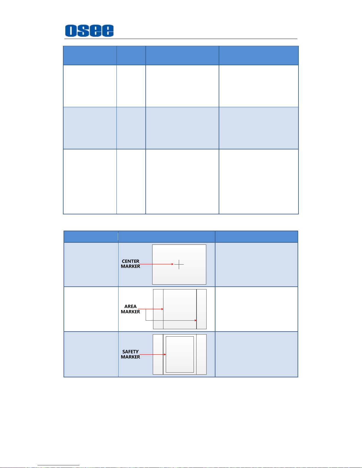
Markers
Marker Illustration Description
CENTER
MARKER
This marker enables
easier checking the center
portion’s focus.
AREA MARKER
This marker displays two
lines to identify an area
with a specified ratio.
SAFETY
MARKER
This marker displays a
rectangle to identify the
safety area with a
specified percentage.
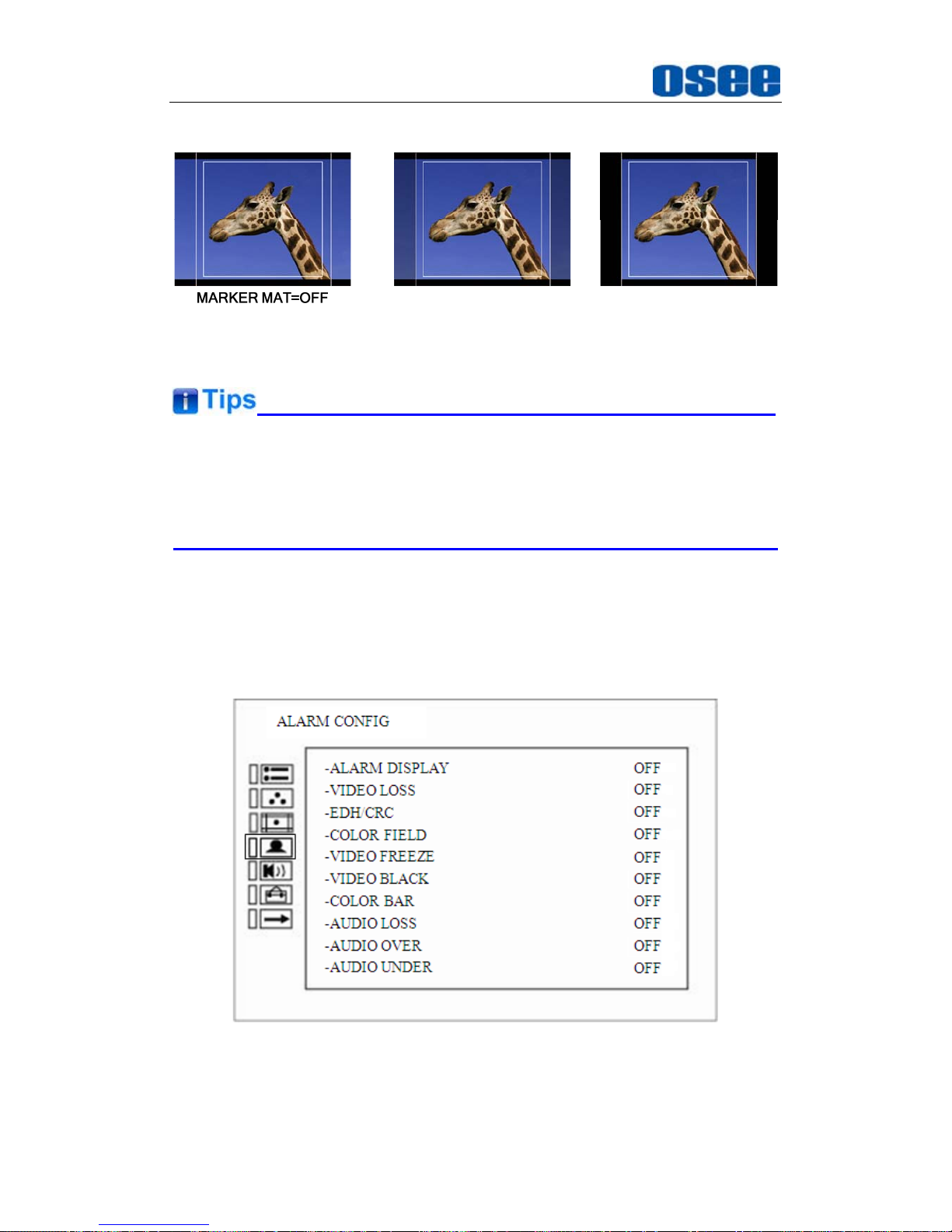
MARKER MAT
The marker mat marks the outside area of the marker display with the
appointed transparency.
For example, set ASPECT as 16:9, AREA MARKER as 4:3, and SAFETY
AREA as 95%, then, the comparison of the three MARKER MATs are as
Page 42
Functionality of the Main Menu
36
shown in Figure 5.1-5:
MARKER MAT=HALF MARKER MAT=BLACK
Figure 5.1-5 MARKER MAT
All markers will be hidden in the following modes though the corresponding
marker is enabled (the value is not OFF): NATIVE.
The safety marker area will change with the area marker.
5.1.4 ALARM CONFIG Menu
The Alarm Config Menu items are used to adjust the parameters displayed
on the screen, the menu items are as shown in Figure 5.1-6:
Figure 5.1-6 Alarm Config Menu
The relationship of Items, Default Value, Domain Range and Description
Page 43
Functionality of the Main Menu
37
of the sub-item is shown in Table 5.1-4:
Table 5.1-4 The Description of Alarm Config Menu Items
Items
Default
Value
Domain Range Description
ALARM
DISPLAY
OFF
<OFF>/<ON> Enable/disable alarm display.
VIDEO LOSS OFF
<OFF>/<ON>
Enable/disable video loss alarm.
EDH/CRC OFF
<OFF>/<ON> Enable/disable EDH/CRC alarm.
COLOR FIELD OFF
<OFF>/<ON>
Enable/disable color field alarm.
VIDEO FREEZE OFF <OFF>/<ON>
Enable/disable video freeze alarm.
VIDEO BLACK OFF
<OFF>/<ON> Enable/disable video black alarm.
COLOR BAR OFF <OFF>/<ON>
Enable/disable color bar alarm.
AUDIO LOSS OFF
<OFF>/<ON> Enable/disable audio loss alarm.
AUDIO OVER OFF <OFF>/<ON>
Enable/disable audio over alarm.
AUDIO UNDER OFF
<OFF>/<ON> Enable/disable audio under alarm.
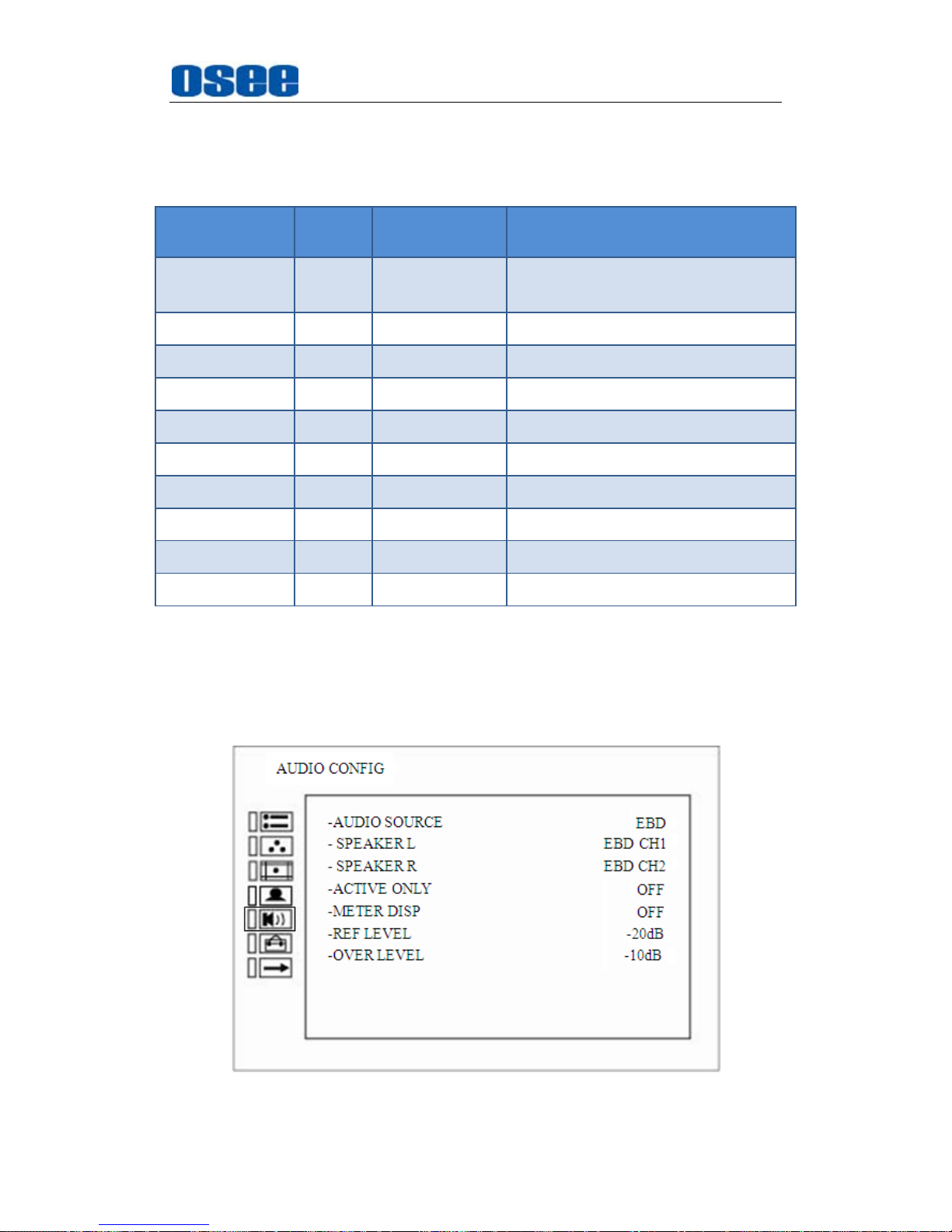
5.1.5 AUDIO CONFIG Menu
The AUDIO CONFIG menu items are used to adjust the audio parameters,
the menu items are as shown in Figure 5.1-7:
Figure 5.1-7 AUDIO CONFIG Menu
Page 44
Functionality of the Main Menu
38
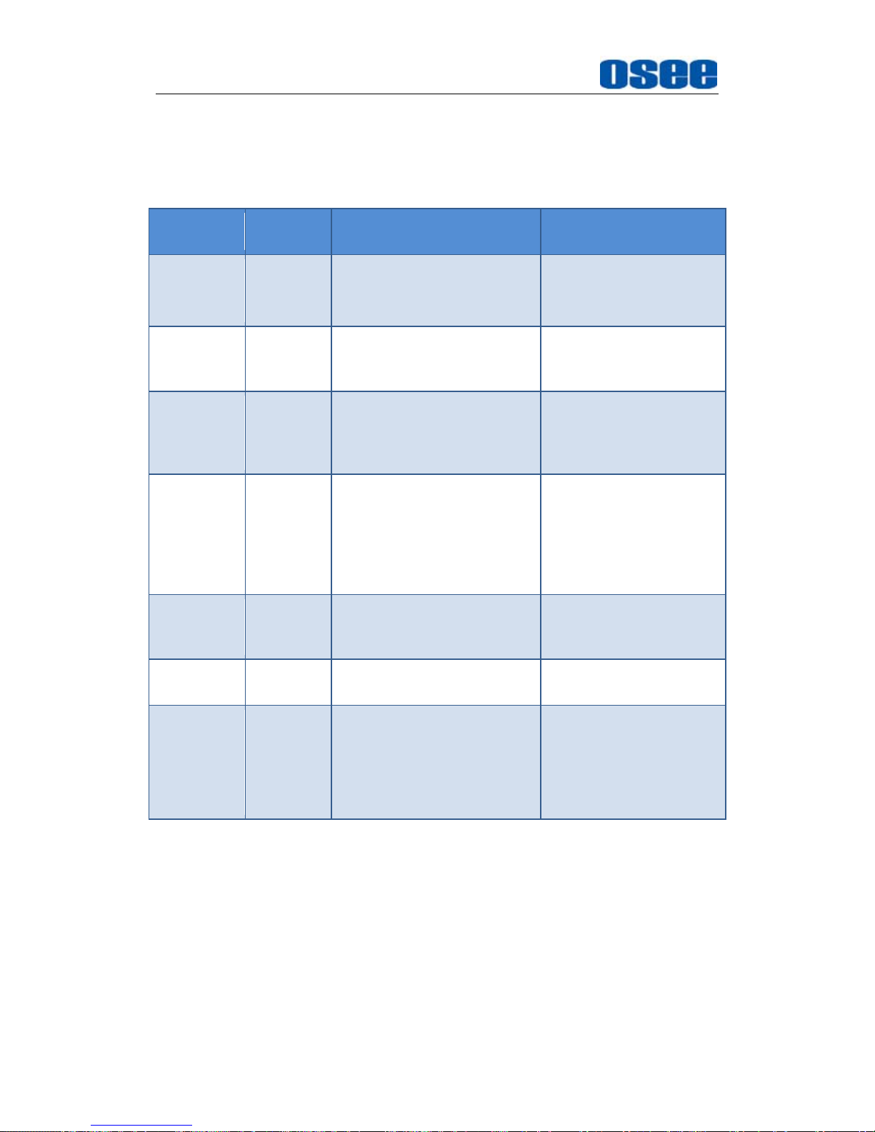
The relationship of Items, Default Value, Domain Range and Description
of the sub-item is shown in Table 5.1-5:
Table 5.1-5 The Description of AUDIO Menu Items
Items
Default
Value
Domain Range Description
AUDIO
SRC
OFF
EBD: embedded signal
EXT: external signal
OFF: no signal
Select external audio
source.
SPEAKER
L
EBD CH1
When the audio source is
EBD, the range of this item
is EBD CH1~ EBD CH16.
Select the embedded
audio channel to the left
speaker and line out.
SPEAKER
R
EBD CH2
When the audio source is
EBD, the range of this item
is EBD CH1~ EBD CH16.
Select the embedded
audio channel to the
right speaker and line
out.
METER DIS OFF
OFF/2CH/4CH/6CH/8CH/
10CH/12CH/14CH/16CH
Set whether to show
audio meter, and select
a meter display mode.
each CH* means the
amount of the channels
to be displayed.
ACTIVE
ONLY
OFF OFF/ON
Display the active
embedded audio group
only
REF LEVEL -20dB -20dB/-18dB
Select the reference
level
OVER
LEVEL
-10dB
-10dB
-8dB
-6dB
-4dB
-2dB
Select the overload level
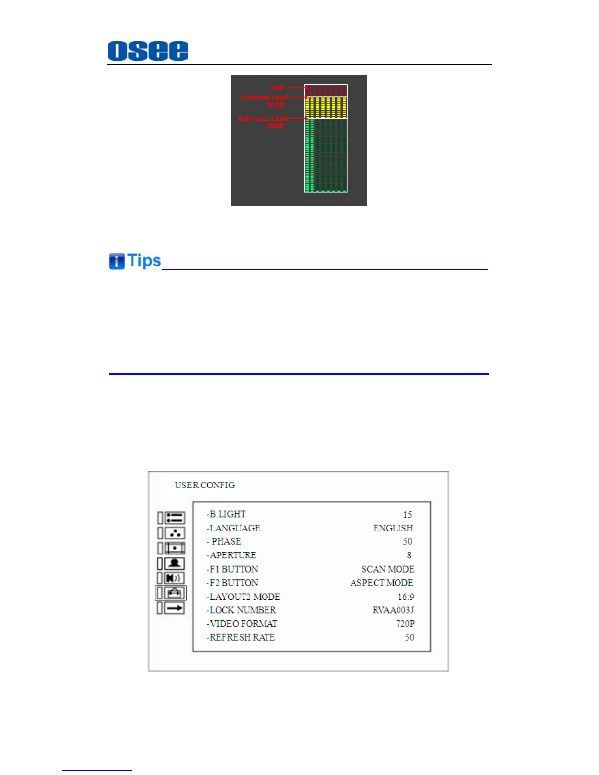
The appearance of Meter is as shown in Figure 5.1-8:
Page 45
Functionality of the Main Menu
39
Figure 5.1-8 Audio Meter
The prerequisite for the available settings of the display mode and the
position of audio meter is that the
METER DIS
is not OFF.
The SDI embedded audio outputs are selected by these items, the HDMI
outputs and analog audio outputs are fixed.
5.1.6 USER CONFIG Menu
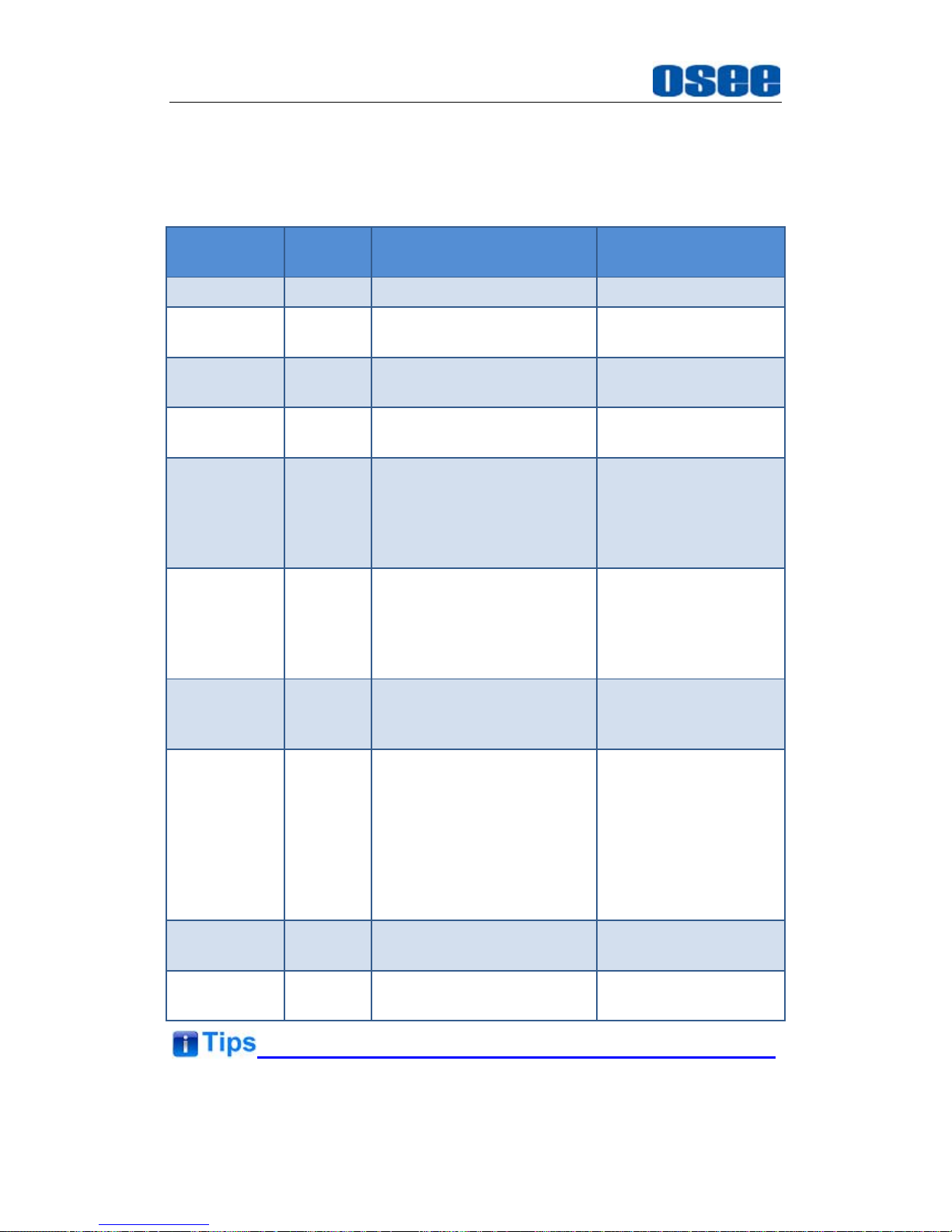
The USER CONFIG menu items are used to adjust the parameters
defined by customers, the menu items are as shown in Figure 5.1-9:
Figure 5.1-9 USER CONFIG Menu
Page 46
Functionality of the Main Menu
40
The relationship of Items, Default Value, Domain Range and Description
of the sub-item is shown in Table 5.1-6:
Table 5.1-6 The Description of USER CONFIG Menu Items
Items
Default
Value
Domain Range Description
BACK LIGHT 15 0~30 Adjust the back light
LANGUAGE ENGLISH ENGLISH/CHINESE
Select a language
mode
PHASE
(NTSC only)
50 0~100 Set the phase
APPERTURE 8 0~100
Set the picture
sharpness
F1 BUTTON MARKER
H/V DELAY, ASPECT,
SCAN, MONO, BLUE
ONLY, NATIVE,
WAVEFORM, AUD
METER, MARKER, NONE
Set a function to F1
button
F2 BUTTON SCAN
MARKER, AUD METER,
WAVEFORM, H/V DELAY,
NATIVE , BLUE ONLY,
MONO, ASPECT, SCAN,
NONE
Set a function to F2
button
LAYOUT2
MODE
16:9 16:9/4:3
Set the aspect ratio for
LAYOUT2(one big left
with three right small)
LOCK
NUMBER
-- --
Function lock code
input, 8 characters.
Each character can
input number or letter.
Note: Be careful to
adjust this option to
avoid unnecessary
mistakes.
VIDEO
FORMAT
720P 720P/1080I/1080P
Set the video output
format.
REFRESH
RATE
50 50/60
Set the video refresh
rate.
The length of LOCK NUMBER is up to 8 characters, you can use the
Page 47
Functionality of the Main Menu
41
combination of these characters: number (0 to 9) and letter (A to Z). Press
ENTER
to edit the LOCK NUMBER, than use UP or
DOWN
to select
characters, than press
ENTER
to go to next character, press
MENU
to exit
editor.
1. SCAN
This product supports the following scan modes:
NORMAL OVER UNDER
Set the function button as [SCAN], press the button continuously to
activate various scan modes.
OVER: Zooms in/out of the image to 96% of its original size
without changing the aspect ratio.
NORMAL: Zooms in/out of the image without changing the aspect
ratio.
UNDER: Zooms in/out of the image without changing the aspect
ratio. Also, displays the data at the top of the horizontal blanking
block.
2. ASPECT
Set the aspect ratio of the screen.
3. BLUE ONLY
It is to activate BLUE ONLY mode that will remove red and green from the
input signal and display the screen only under a blue signal.
4. MONO
It is to activate MONO mode that will display the screen in monochrome
presentation, inactivate this mode to display the screen in color mode.
Press F1/F2 button to activate the assigned function and adjust the
parameter value.
The
SCAN
mode or the ASPECT mode is not selectable when Native mode
is set to ON.
Page 48
Functionality of the Main Menu
42
5.1.7 OSD CONFIG Menu
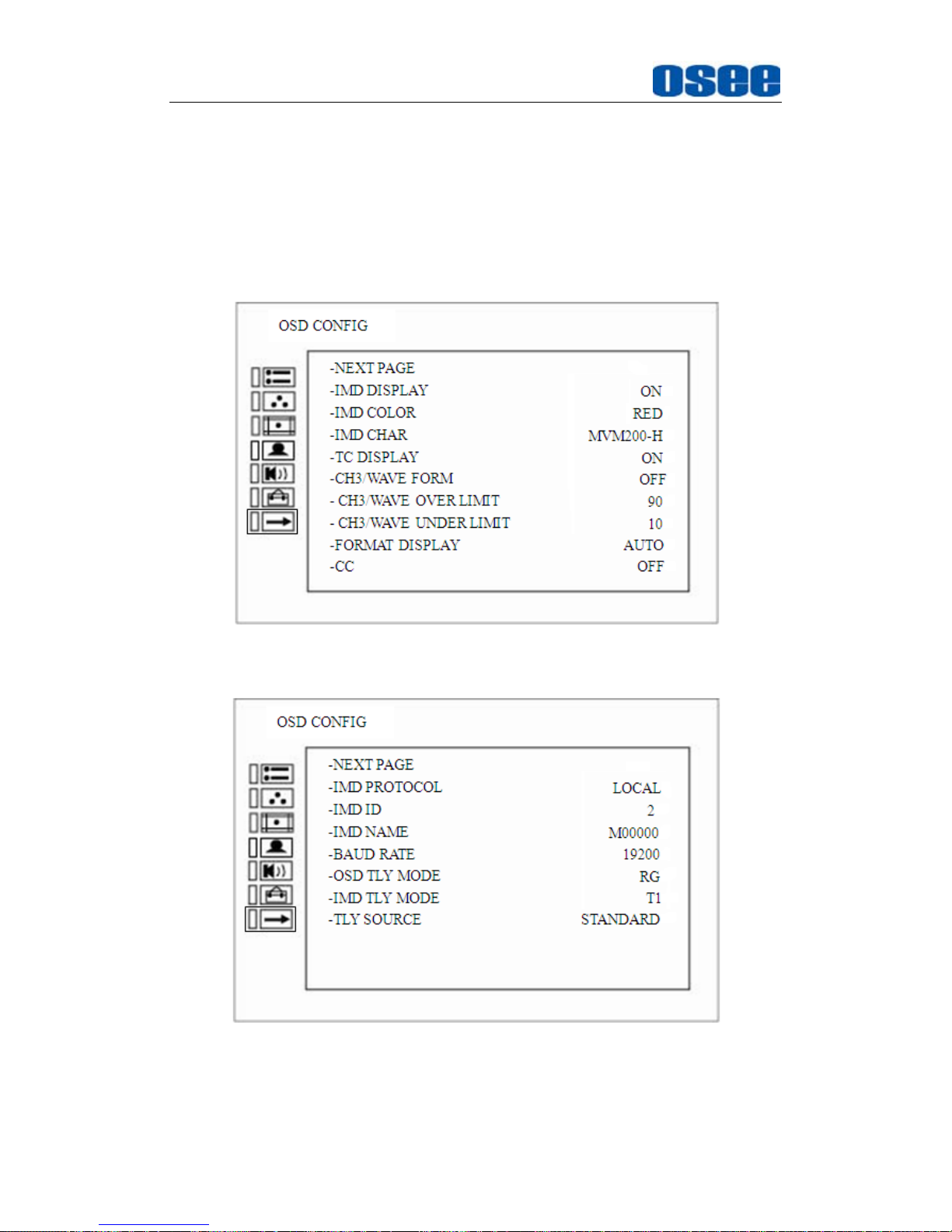
The OSD CONFIG menu items are used to adjust the parameters defined
for IMD display and other OSD parameters, there are two pages of
parameters for this menu, select
NEXT PAGE
item at the first line of the
parameter list and press
Enter
button to turn page, the menu items are as
shown in Figure 5.1-10 and Figure 5.1-11:
Figure 5.1-10 OSD Menu-Page1
Figure 5.1-11 OSD Menu-Page2
The relationship of Items, Default Value, Domain Range and Description
Page 49
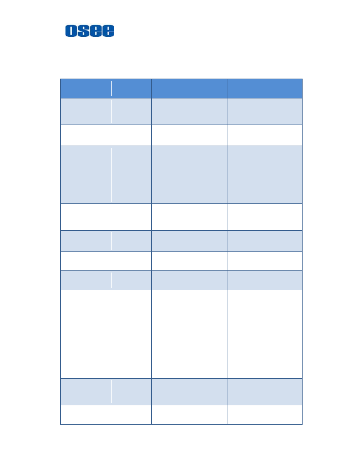
Functionality of the Main Menu
43
of the sub-item is shown in Table 5.1-7:
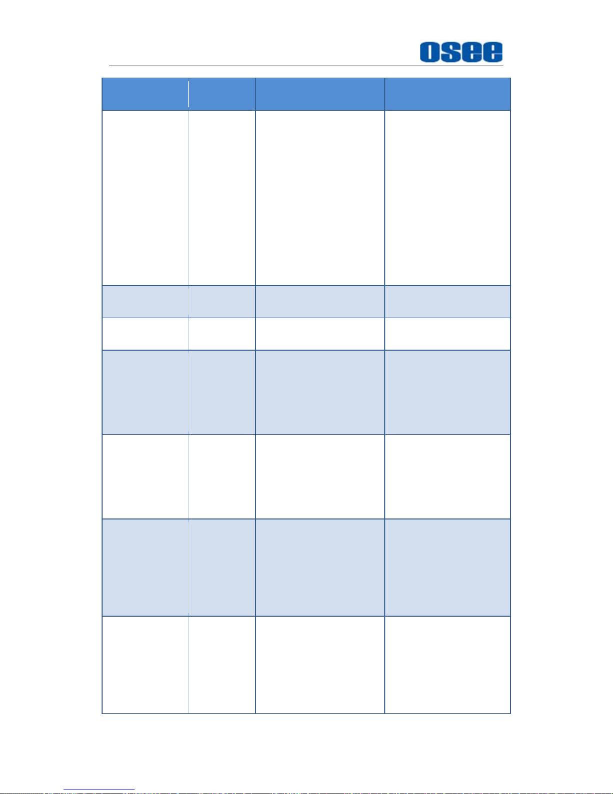
Table 5.1-7 The Description of IMD Menu Items
Items
Default
Value
Domain Range Description
IMD DISPLAY ON OFF/ON
Set whether to display
IMD CHARACTER on
screen.
IMD COLOR RED
RED/GREEN/YELLOW/
WHITE
Set the color for IMD
CHARACTER.
IMD CHAR XXXXXXXX --
Set the IMD string
displayed on the
screen. After entering
this item, press Up or
Down to choose your
character for this IMD
string.
TC DISPLAY OFF
OFF/LTC/VITC
Set whether to display
TC, and select a mode
for TC display.
CH*WAVE
FORM
OFF
OFF/VECT100/VECT75/
WAVE FORM
Set the display mode of
wave form.
CH*WAVE
OVER LEVEL
100
0~100
Select the overload
level for WAVE FORM.
CH*WAVE
UNDER LEVEL
0 0~100
Select the under level
for WAVE FORM.
FORMAT
DISPLAY
AUTO
OFF: the display is
hidden
AUTO: the input
source and format
are displayed for
about 10 seconds
when the input of the
signal changes
ON: the input source
and format are
always displayed
Set whether to display
status information.
If the signal input is not
equal to "No signal" and
this item is auto, the
status information will
show 10 seconds when
the status changed, and
then closed
automatically.
CC ON OFF/ON
Set whether to display
caption
information.(Reserved)
IMD
PROTOCAL
LOCAL
LOCAL: Use IMD
setting to control.
Select an IMD protocol
Page 50
Functionality of the Main Menu
44
Items
Default
Value
Domain Range Description
TSL3.1: Use the
TSLV3.1 protocol
setting to control.
TSL4.0: Use the
TSLV4.0 protocol
setting to control.
IMAGE VIDEO: Use
the Image video
protocol setting to
control.
UDP: Use the UDP
protocol setting to
control.
IMD ID 0 0~255
Set the ID number for
each monitor
IMD NAME XXXXXXXX
Set an IMD name for
each screen.
BAUD RATE 38400 9600/19200/38400
Select a baud rate for
communication. TSL
V3.1 and TSL V4.0 is
38400, Image video is
one of the
9600/19200/38400.
OSD TLY
MODE
RG
RG: Red/Green
GR: Green only
RGY:
Red/Green/Yellow
OFF: No tally light
Select the OSD Tally
mode. Only the TALLY
SOURCE is
STANDARD or
STANDARD + IV422,
the setting is available.
IMD TLY MODE T1
T1/T2/T1T2/T2T1/T1-/
T2-/T1T2-/T2T1-
Select the IMD Tally
mode.
Use this setting when
using the Image Video
tally control, this setting
will determine the state
which is selected.
TLY SOURCE STANDARD
STANDARD: Use
the Standard setting
to control tally via
contact closure on
GPI tally.
IMAGE VIDEO 422:
Use the setting to
Select the source for
tally source
Page 51
Functionality of the Main Menu
45
Items
Default
Value
Domain Range Description
control tally state via
422 ports, GPI
toggle is no
available.
TSL: Use the TSL
422 setting to
control OSD and
LED tally via the TSL
serial protocol.
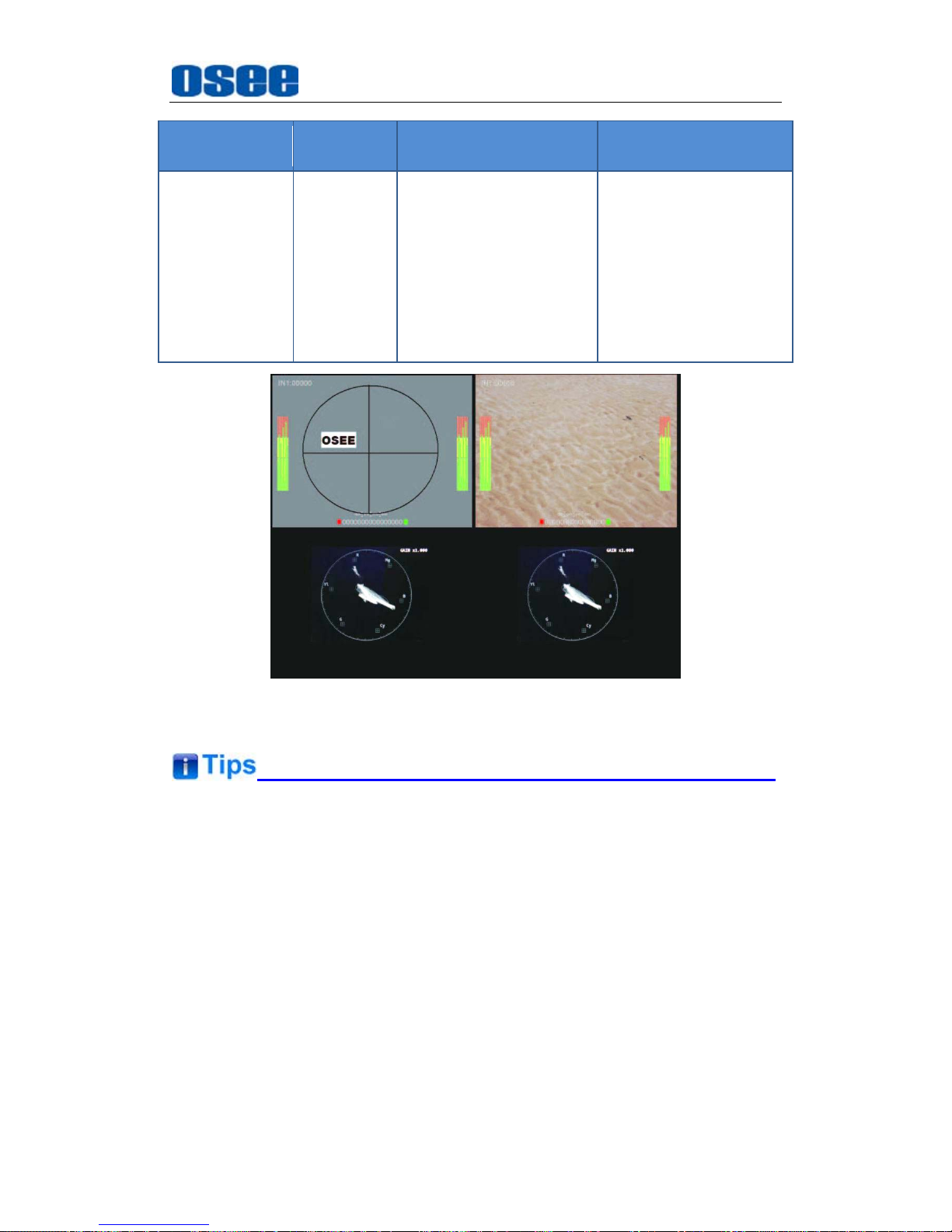
Figure 5.1-12 Wave Form
If IMD DISPLAY item is ON, the IMD CHARACTER in the black bar will
display on the bottom of the corresponding window.
Only CH1 and CH3 have wave form and vector functions, and the wave
form and vector parameters settings for CH1 is set in the menu list of CH2,
and the settings for CH2 is set in the menu list of CH4. When the
CH*WAVE FORM is not OFF, the wave form or vector of CH1 is displayed
in the display window of CH2, and the wave form or vector of CH3 is
displayed in the display window of CH4, for example, as shown in Figure
5.1-12.
The length of IMD NAME and IMD CHARACTER is up to 16 characters.
Page 52
Functionality of the Main Menu
46
The character range is from 0x00 to 0x7F of ASCII. Press
ENTER
to edit
the IMD characters, than use UP or
DOWN
to select characters, than press
ENTER
to go to next character, press
MENU
to exit editor.
5.2 Menu Settings
When checking or modifying the value of the menu item, cooperating with the
following buttons: MENU, UP, DOWN, ENTER.
1. Operations to the Main menu
Display the Main Menu
Press MENU button to enter into the main menu, it displays at the top
left corner of the screen.
Switch menu items
After displaying the main menu, press UP or DOWN button to choose a
menu item, the menu item selected is in yellow.
Back to the Main menu
After entering to a sub-menu item or a sub-menu item value, press
MENU button to back to the upper level menu area.
Close the Main menu
Press MENU button to close the Main menu when the control icon is in
the Main menu item.
After you have loaded the Main menu, it will be closed automatically if you
do nothing operation with it in 60s.
2. Operations to sub-menu item
Display the sub-menu item
After display the Main menu, press UP or DOWN button to select a
menu item, and the right part displays its sub-menu items according to
the current selected menu item.
Switch sub-menu items
After displaying the sub-menu items list, press ENTER button to enter
Page 53
Functionality of the Main Menu
47
into the sub-menu items list, press UP or DOWN button to choose a
sub-menu item, a yellow rectangle is in front of the selected sub-menu
item.
Back to menu item
After entering to the sub-menu item value, press MENU button to back
to menu items, or after setting the sub-menu item value and press Enter
button to firm the modification, the control icon is back to the
corresponding sub-menu item.
3. Operations to sub-menu item value
Switch sub-menu item value
When the control icon is in sub-menu item value, press UP or DOWN
button to switch among its value list.
Confirm the modification to sub-menu item value
Press ENTER button to confirm the selection of a value, and the control
icon is back to the corresponding sub-menu item.
Abandon the modification to sub-menu item value
Press MENU button to give up the modification to sub-menu item value,
and the control icon is back to the corresponding sub-menu item.
The value in white color is modifiable, and the value in blue color is
unmodifiable.
4. Selecting the Menu Language
You can select one of languages (English or Chinese) for displaying the
menu. The default language for the menu is Chinese. The following will
teach you how to switch to ENGLISH.
Operation:
Step 1 Select USER CONFIG menu
Press MENU button to display the OSD menu, click DOWN button to
select USER CONFIG menu.
Step 2 Select the value of the Language item
Press ENTER button to get into the USER CONFIG menu items, and
click DOWN button to select the sub-item LANGUAGE, then, click
ENTER button to get into the sub-value list, the current control icon is in
Page 54
Functionality of the Main Menu
48
Chinese.
Step 3 Confirm the modification of the value of sub-item
Click DOWN button to select the sub-item LANGUAGE to English,
press ENTER button to confirm the modification.
Step 4 Exit the main menu
Click MENU button to exit the main menu.
5. Network Control
MVM-200 supports network interface. Connect a computer with
MVM-200 through this interface to achieve the network control to
MVM-200.
This chapter will introduce how to set and check the parameters of
MVM-200 in Internet Explorer.
Use Internet Explorer to enter into a web control page. For example,
input http://192.168.1.138 in address bar, it will display the then, press
Enter key, the management interface of MVM-200 is displayed. Set the
parameters in this web page.
The network address of the computer which is connected with MVM-200
and the network address of MVM-200 must be in the same segment.
Page 55
Specifications
49
Chapter 6 Specifications
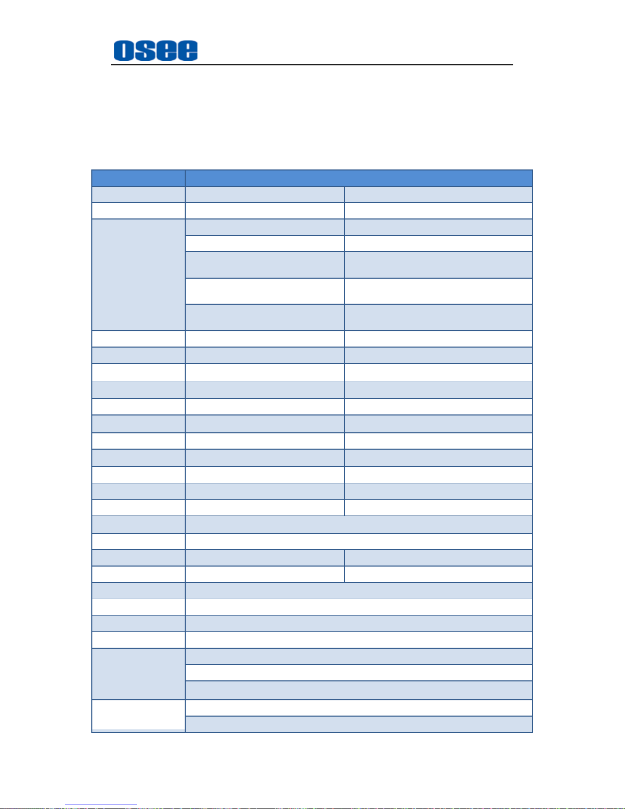
1. Product detailed information
Specification
V
alues
Model MVM-170 MVM-200
Dimension 17.3” 19.5”
Dimension(WxHxD)
--- 454.6x266.8x44.2mm(Without accessory)
--- 483.6x266.8x44.2mm(With rackmount bracket)
---
454.6x310.3x44.2mm(With extra control
buttons bar)
421.8x308.1x160mm (With monitor
stand)
454.6x318.2x160mm(With extra control buttons
bar and monitor stand)
421.8x264.3x45.5mm(Without monitor
stand)
454.6x266.8x44.2mm(Without optional
accessories or with only wallmount bracket)
Pixel Pitch (WxH) 0.1989×0.1989mm 0.2259×0.21874mm
Aspect Ratio 16:9 16:9
Display Area (WxH)
381.89ⅹ214.81mm 433.73ⅹ236.24mm
Viewing Angle (HxV)
178°x178° 178°x178°
Color Depth 262K colors 16.7M colors (6bit + A-FRC)
Resolution
1920×1080 1920×1080
Contrast (Typ.) 700:1 1000:1
Luminance (cd/㎡)
300 250
Response Time (ms) 14 14
Backlight RGB LED WHITE LED
Backlight Life(Hrs) 15000 30000
Work Temperature
0°C~50°C
Power Supply DC18~20V
Power Consumption Approx. 50W Approx. 51W
Weight --- >7kg
Video Input Interface BNC(X4, CVBS,3G/HD/SD-SDI adaptable), HDMI(X1 HDMI/DVI-D adaptable)
Video Output Interface BNC(X4, CVBS, 3G/HD/SD-SD Ioop-out), HDMI(X1, HDMI/DVI combined)
Audio Input Interface 4 pairs of Analog Stereo, RCA(X8), SDI embedded audio
Audio Output Interface 1 pair of Analog Stereo, RCA(X2)
Control Interface
GPI(DB9)X1
RS485(cascade RJ45) X2
Ethernet(10/100M adaptive RJ45) X1
Signal Formats
CVBS: PAL, NTSC
SD-SDI: 480i60, 576i50
Page 56
Specifications
50
Specification
V
alues
HD-SDI: 1080i50, 1080i 59.94, 1080i 60, 720p50, 720p 59.94, 720p 60, 1035i59.94, 1035i
60
3G-SDI: 1080p50, 1080p60
CVBS Input/Output
Signal Type NTSC, PAL
Signal Amplitude 1Vp-p+/-3dB
Impedance 75Ω
Return Loss >40 dB to 5 MHz
DC Offset 0V±0.05 V
Frequency Response ±0.2 dB to 5 MHz
Differential Gain <1%
Differential Phase <1.5°
3G-SDI /HD-SDI /SDI-SDI Input/Output
Signal Type SMPTE 424M, SMPTE 292M, SMPTE 259M, SMPTE 297M, SMPTE ST 2048-2
Connector BNC per IEC 169-8
Impedance 75Ω
Return Loss
>18 dB 5 to 270 MHz
>15 dB 270 MHz to 1.5 GHz
>10 dB up to 3 GHz
Maximum Signal Level 800 mV pk-pk 10%
Signal Amplitude 800 mV pk-pk 10%
DC Offset 0 V ±0.5 V
Overshoot <10%
Jitter <0.2 UI
Rise/Fall Time
<700 ps for SD
<270 ps for 1.5 Gb/s HD
<135 ps for 3 Gb/s HD
Extinction Ratio >8
Back Reflection <-14 dB
*The unit about the appearance attributes in above table is mm.
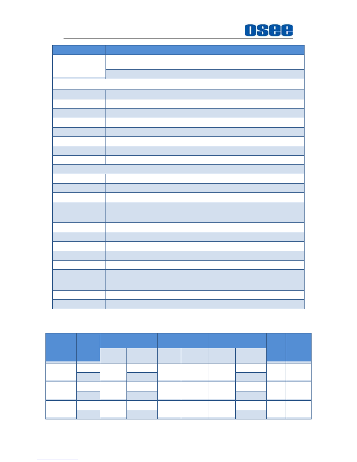
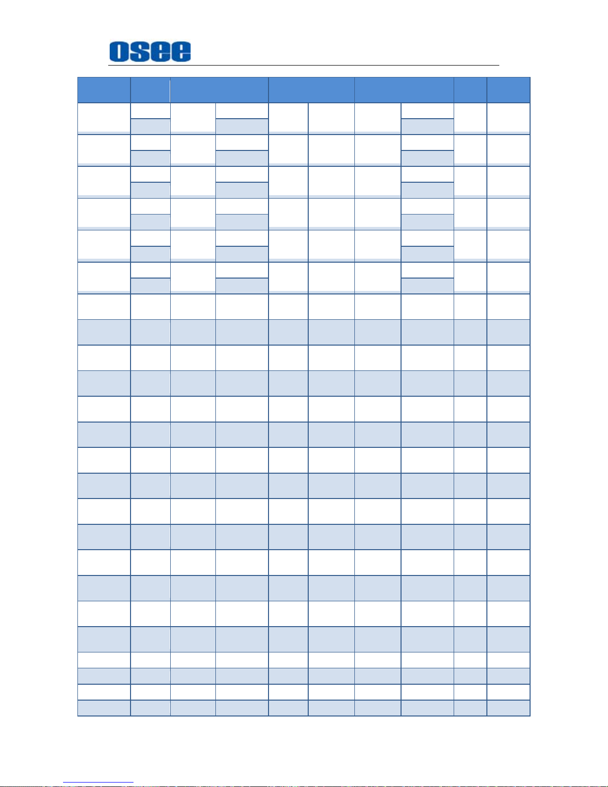
2. Input/Output Resolution, Frame Refresh Rate and Color Matrix
ASPECT
RATIO
OVERSCAN NATIVE
FULL
NORMAL
Frame
Rate
Color
Matrix
INPUT OUTPUT INPUT OUTPUT
INPUT
ALL
OUTPUT
NORMAL
NTSC
16:9
684X462
1920X1080
720X487 720X487 720X487
1920X1080
60 601
4:3 1440X1080 1440X1080
PAL
16:9
684X548
1920X1080
720X576 720X576 720X576
1920X1080
50 601
4:3 1440X1080 1440X1080
SECAM
16:9
684X548
1920X1080
720X576 720X576 720X576
1920X1080
50 601
4:3 1440X1080 1440X1080
Page 57
Specifications
51
ASPECT
RATIO
OVERSCAN NATIVE
FULL
NORMAL
Frame
Rate
Color
Matrix
NTCS-4.43
16:9
684X462
1920X1080
720X487 720X487 720X487
1920X1080
60 601
4:3 1440X1080 1440X1080
PAL-M
16:9
684X462
1920X1080
720X487 720X487 720X487
1920X1080
60 601
4:3 1440X1080 1440X1080
480I60
16:9
684X462
1920X1080
720X487 720X487 720X487
1920X1080
60 601/709
4:3 1440X1080 1440X1080
576I50
16:9
684X548
1920X1080
720X576 720X576 720X576
1920X1080
50 601
4:3 1440X1080 1440X1080
480P60
16:9
684X462
1920X1080
720X487 720X487 720X487
1920X1080
60 601/709
4:3 1440X1080 1440X1080
576P50
16:9
684X548
1920X1080
720X576 720X576 720X576
1920X1080
50 601
4:3 1440X1080 1440X1080
720P24 16:9 1216X684 1920X1080
1280x72
0
1280x720 1280x720 1920X1080 48 709
720P25 16:9 1216X684 1920X1080
1280x72
0
1280x720 1280x720 1920X1080 50 709
720P30 16:9 1216X684 1920X1080
1280x72
0
1280x720 1280x720 1920X1080 30 709
720P50 16:9 1216X684 1920X1080
1280x72
0
1280x720 1280x720 1920X1080 50 709
720P60 16:9 1216X684 1920X1080
1280x72
0
1280x720 1280x720 1920X1080 60 709
1035I60 16:9 1824X984 1920X1080
1920X10
35
1920X1035 1920X103
5
1920X1080 60 709
1080I60 16:9
1824X102
6
1920X1080
1920X10
80
1920X1080 1920X108
0
1920X1080 60 709
1080I50 16:9
1824X102
6
1920X1080
1920X10
80
1920X1080 1920X108
0
1920X1080 50 709
1080P24 16:9
1824X102
6
1920X1080
1920X10
80
1920X1080 1920X108
0
1920X1080 48 709
1080P25 16:9
1824X102
6
1920X1080
1920X10
80
1920X1080 1920X108
0
1920X1080 50 709
1080P30 16:9
1824X102
6
1920X1080
1920X10
80
1920X1080 1920X108
0
1920X1080 60 709
1080P50 16:9
1824X102
6
1920X1080
1920X10
80
1920X1080 1920X108
0
1920X1080 50 709
1080P60 16:9
1824X102
6
1920X1080
1920X10
80
1920X1080 1920X108
0
1920X1080 60 709
1080SF24 16:9
1824X102
6
1920X1080
1920X10
80
1920X1080 1920X108
0
1920X1080 48 709
VGA 640X480 1920X1080 60-75
SVGA 800X600 1920X1080 60-75
XGA 1024x768 1920X1080 60-75
SXGA 1280x102 1920X1080 60-75
Page 58
Specifications
52
ASPECT
RATIO
OVERSCAN NATIVE
FULL
NORMAL
Frame
Rate
Color
Matrix
4
UXGA
1600x120
0
1920X1080 60
WXGA 1360X768 1920X1080 60
WUXGA
1920x120
0
1920X1080 60
*Don’t display all OSD when SCAN is NATIVE.
*Don’t display MARKER when SCAN is NATIVE.
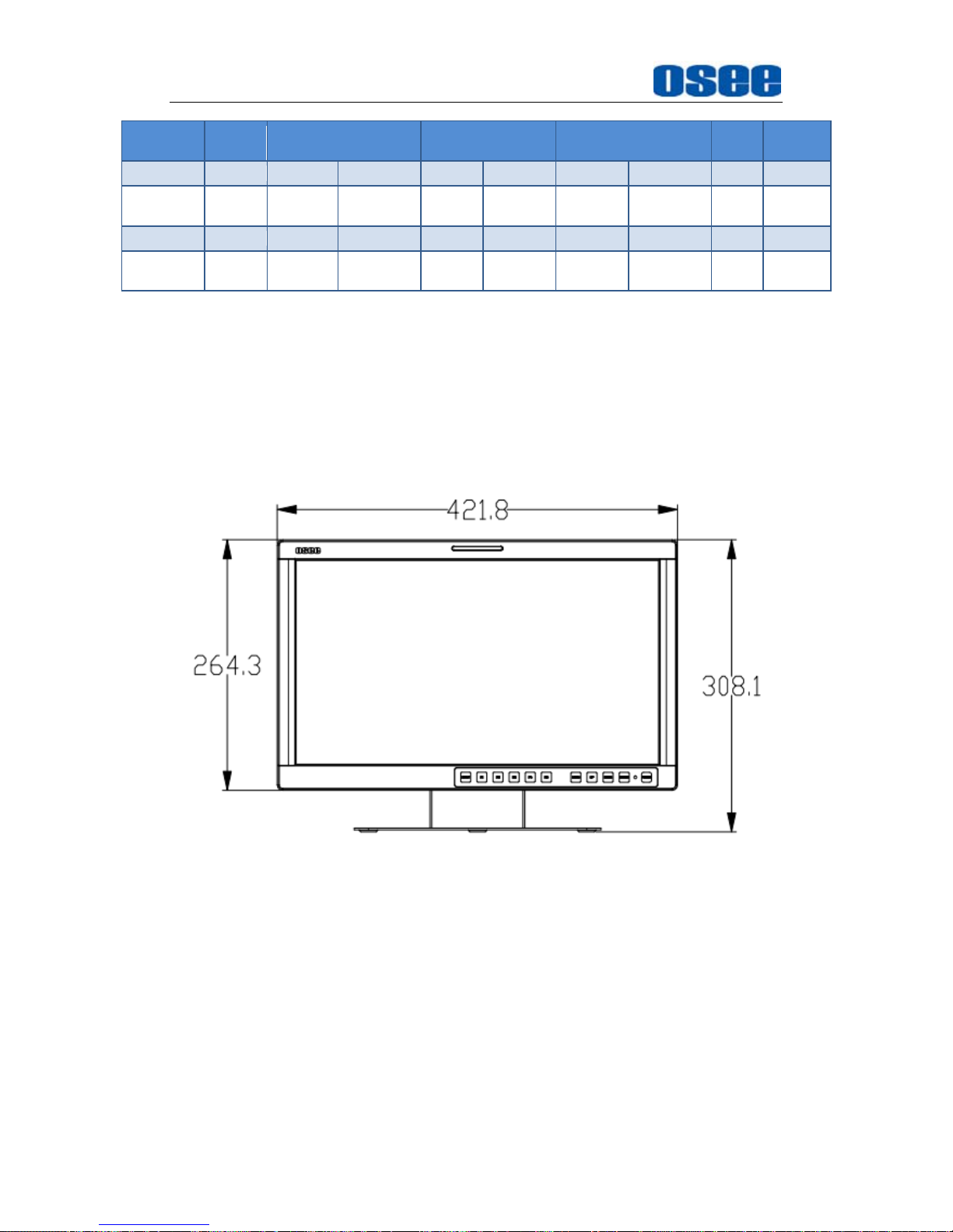
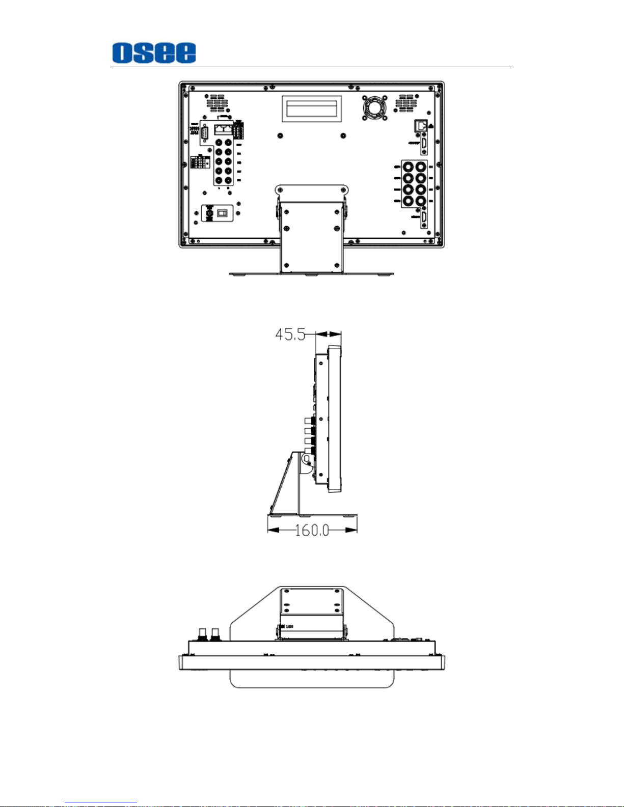
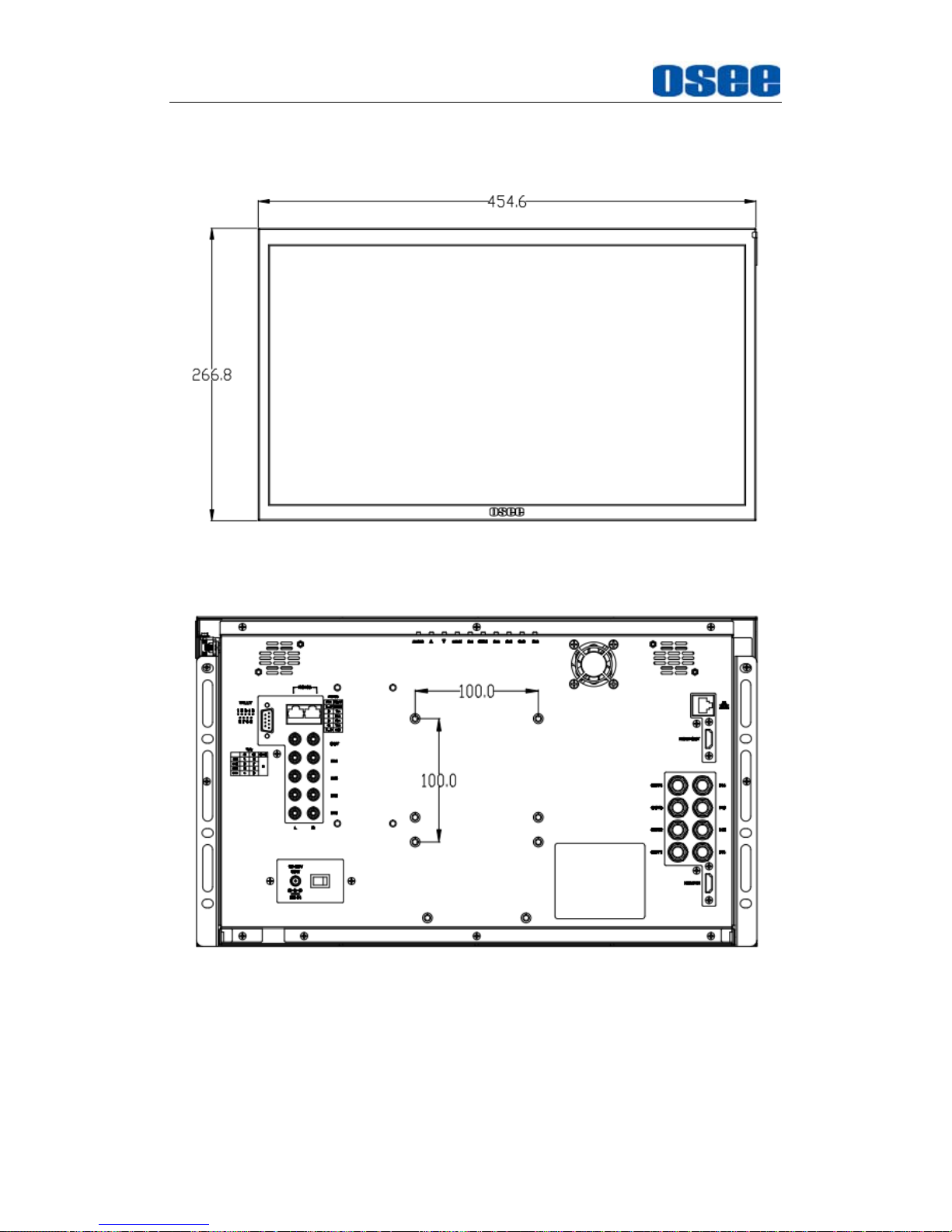
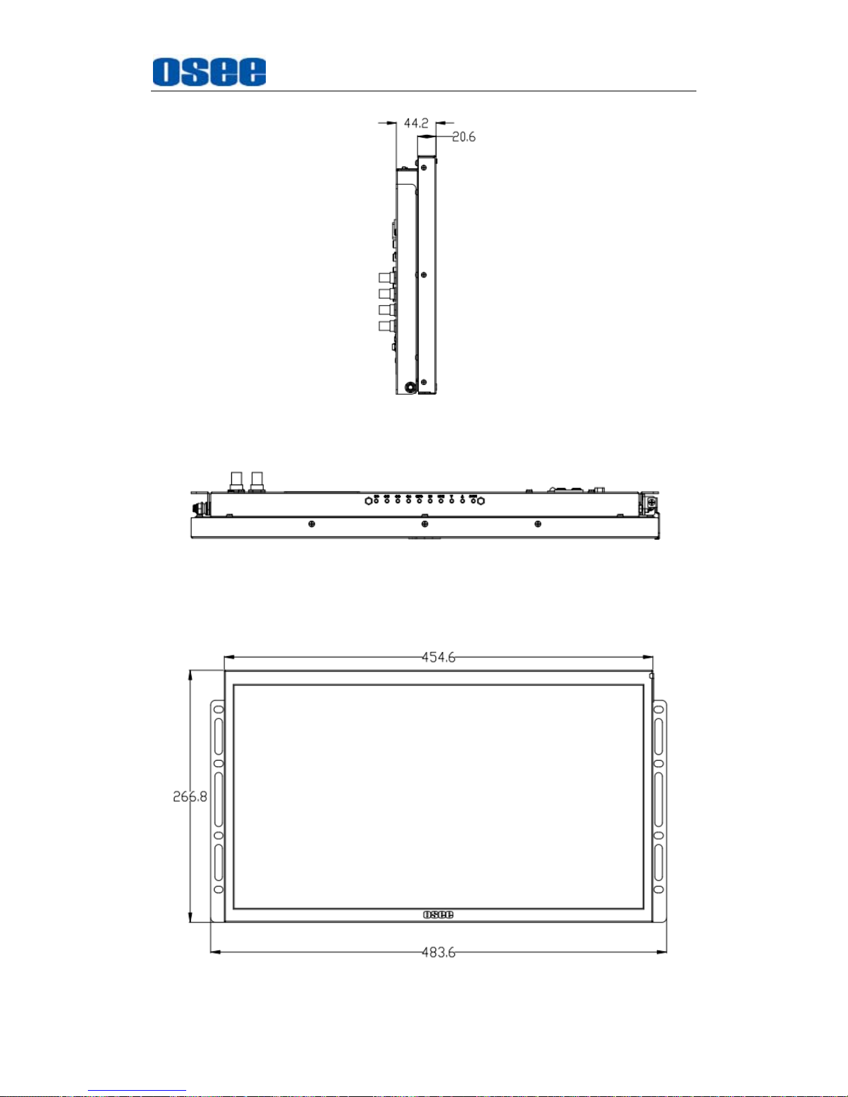
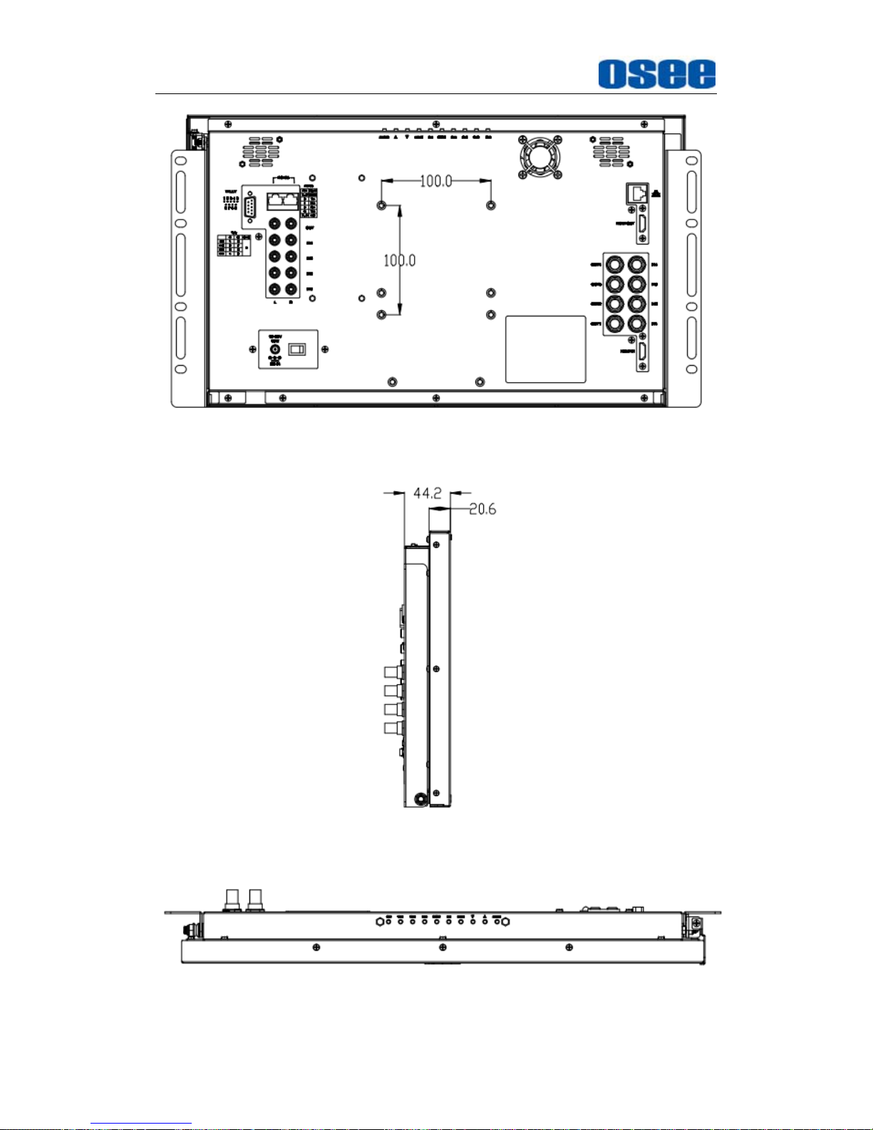
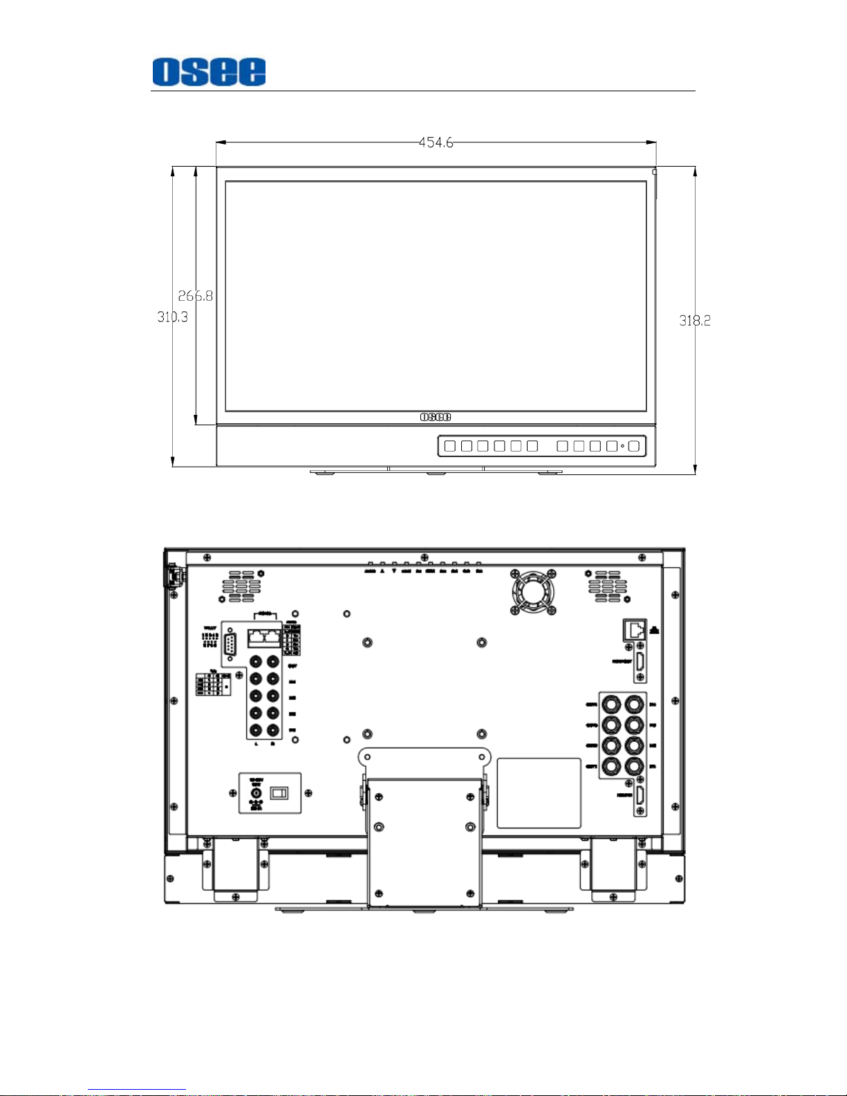
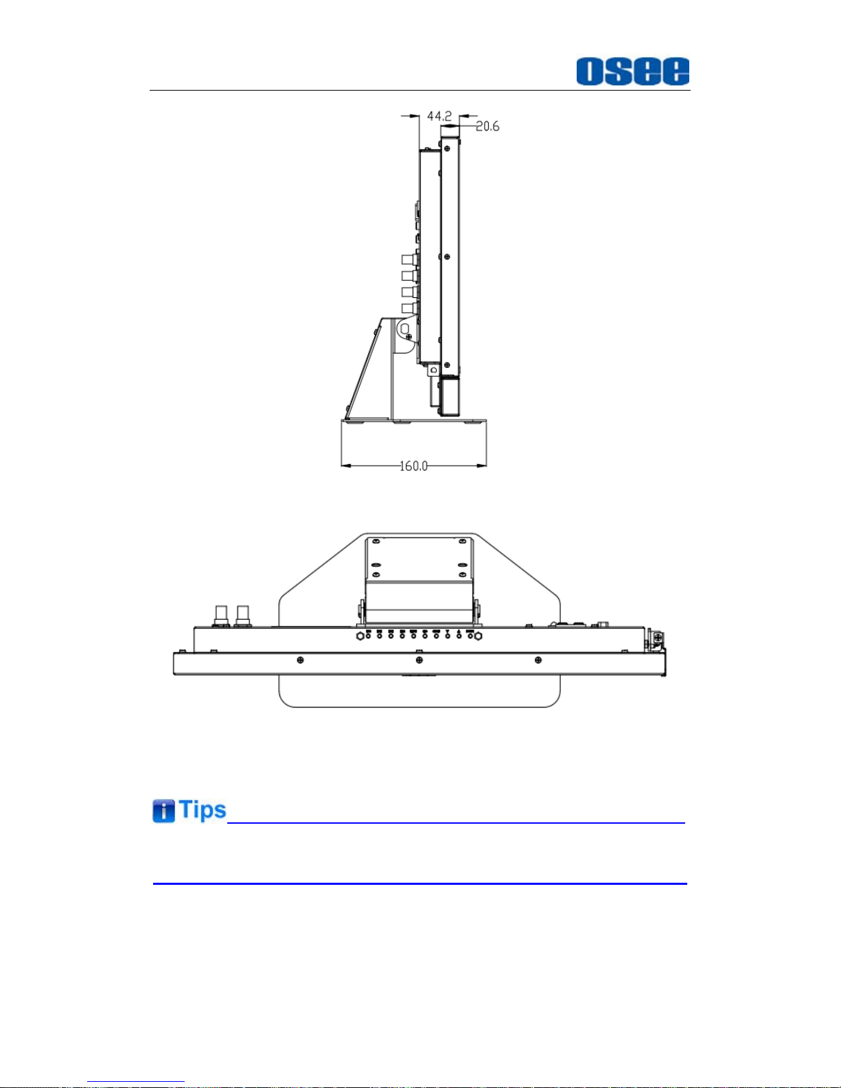
3. Dimensions
The description of the product dimensions is shown as in the following
figures(Unit: mm):
MVM-170
Figure 6-1 Front Panel(Unit: mm)
Page 59
Specifications
53
Figure 6-2 Rear Panel(Unit: mm)
Figure 6-3 Side View(Unit: mm)
Figure 6-4 Top View(Unit: mm)
Page 60
Specifications
54
MVM-200
Figure 6-5 Front Panel(Unit: mm)
Figure 6-6 Rear Panel(Unit: mm)
Page 61
Specifications
55
Figure 6-7 Side View(Unit: mm)
Figure 6-8 Top View(Unit: mm)
MVM200 –With rackmount brackets
Figure 6-9 Front Panel(Unit: mm)
Page 62
Specifications
56
Figure 6-10 Rear Panel(Unit: mm)
Figure 6-11 Side View(Unit: mm)
Figure 6-12 Top View(Unit: mm)
Page 63
Specifications
57
MVM-200 –With monitor stand and extra control buttons bar
Figure 6-13 Front Panel(Unit: mm)
Figure 6-14 Rear Panel(Unit: mm)
Page 64
Specifications
58
Figure 6-15 Side View(Unit: mm)
Figure 6-16 Top View(Unit: mm)
Specifications are subject to change without notice.
------------------No Text Below------------------
Page 65
FOR MORE INFORMATION PLEASE VISIT: http://www.osee-dig.com/
OSEE TECHNOLOGY CO., LTD.
No.22 Building, No.68 zone, Beiqing Road, Haidian District, Beijing, China
Tel: (+86) 010-62434168, Fax: (+86) 010-62434169
E-mail: [email protected]
 Loading...