

Page 1

LMW-171 SERIES LCD MONITOR
USER MANUAL
Page 2
PRODUCT INFORMATION
MODEL: LMW-171 SERIES LCD MONITOR
Version: V010200
Release Date: 2010-7-30
COMPANY NAME
Beijing Osee Digital Technology Ltd.
CONTACT INFORMATION
Address: Room 702, Tower D, Jinyujiahua Building, No.9, 3rd Shangdi Street, Haidian
District, Beijing, China
Post code: 100085
Tel: 8610-62968823
Fax: 8610-62977165
Http://www.osee-dig.com
E-mail:[email protected]
Page 3

About The USER MANUAL
The user manual applies to the following device types:
z LMW-171H
z LMW-171S
z LMW-171V
The images of LMW-171H are adopted in the following descriptions. Any of the different
specifications between the device types are elaborated. Before reading the manual, please
confirm the device type.
Page 4

Contents
Chapter 1 Product Overview..............................................................................................1
Chapter 2 Unpacking and Installation............................................................................... 1
Chapter 3 Dimensions.......................................................................................................... 2
Chapter 4 Operation............................................................................................................4
4.1 Status Display............................................................................................................................. 4
4.2 Input Signals................................................................................................................................5
4.3 Rear Panel Terminals.................................................................................................................6
4.4 Location and Function of Control Buttons And Knobs On Front Panel.............................10
4.5 Input Signals and Adjustable/setting Items............................................................................13
Chapter 5 Menu Operation Guide ................................................................................... 14
5.1 Selecting the Menu Language ..................................................................................................14
5.2 Using the Menu..........................................................................................................................15
Chapter 6 LMW-171 Series LCD Monitor Menu Structure......................................... 16
6.1 Main Menu.................................................................................................................................16
6.2 Adjusting and Changing the Settings......................................................................................16
Chapter 7 Technical Specifications...................................................................................29
7.1 Product Detailed Information:............................................................................................. ....29
7.2 Inputs .........................................................................................................................................29
7.3 Component Level Definition ....................................................................................................29
7.4 Standard Definition Video, Frame Refresh Rate and Color Matrix (1920×1200)...............30
Chapter 8 Supplied Accessories........................................................................................ 32
Page 5

LMW-171 SERIES LCD MONITOR User Manual
—1—
Chapter 1 Product Overview
The LM171 is a cost-effective 17 inch LCD monitor that can be used for post production rooms,
broadcasters and mobile units, monitoring multi-format high definition video and audio.
The LM171 is equipped with 1366×768 high resolution panel and capable of displaying 1080 format high
definition signal at native resolution. Advanced digital video processing technology such as precise 3D
de-interlace, scaling, Gamma and color correction is used to ensure high display quality.
The LM171H can accept Video, S-video, component, SDI and HDMI format SD/HD video signal as well as
VGA or DVI PC signal.
It has various On-Screen Display feature, can display 8 channels of audio meter, time code, UMD and tally
on the LCD panel. Other features like H/V delay, NATIVE, blue/mono display, area marker and safety
marker are standard for the monitor.
Features
1366×768 Native Resolution Panel
High Quality Color Reproduction
Various Area, Safety and Center Marker
H/V Delay, NATIVE, Blue/Mono Display
8 Channel Audio Meters, Time code,UMD, Tri-color Tally
Field upgradeable
Audio De-embedding for SDI Input
Build-in Speaker and Audio Line Output
Chapter 2 Unpacking and Installation
Unpack the LMW-171 Monitor and inspect for any apparent physical damage that may have occurred in
transit. Standard and optional accessories are covered in Chapter 8 of this manual.
We recommend you retain the shipping carton for future use.
1. When installing a mount option, please assure a soft and non-scratch surfaced is used to place the
monitor on.
2. Place the monitor on the soft surface screen face down for installation of table stand or mount.
3. The following are optional accesories, if necessary, please contact the manufacturer.
y Use the included 2 pieces of GB818 M5*5 screws to attach the Rackmount Ear option on both side
of the monitor.
y Use the included 4 pieces of GB819 M3*12 screws to attach the Battery mounter option on the rear
center.
y Use the included 2 pieces of GB818 M4*13 screws to attach the handle option at the top.
4. Place the LMW-171 in the required location for operation.
5. Connect the required signals. For BNC connections use 75Ω rated connectors.
6. Connect A.C. Mains power using the included EIC power cord. Please ensure an Earth ground
present to ensure proper operation of the unit.
7. As a final step turn on the mains power using the toggle switch located on the rear of the LMW-171
above the power connection.
Page 6
LMW-171 SERIES LCD MONITOR User Manual
—2—
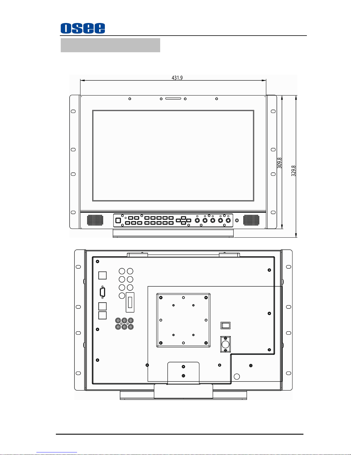
Chapter 3 Dimensions
Front View (Unit: mm)
Rear View (Unit: mm )
Page 7
LMW-171 SERIES LCD MONITOR User Manual
—3—
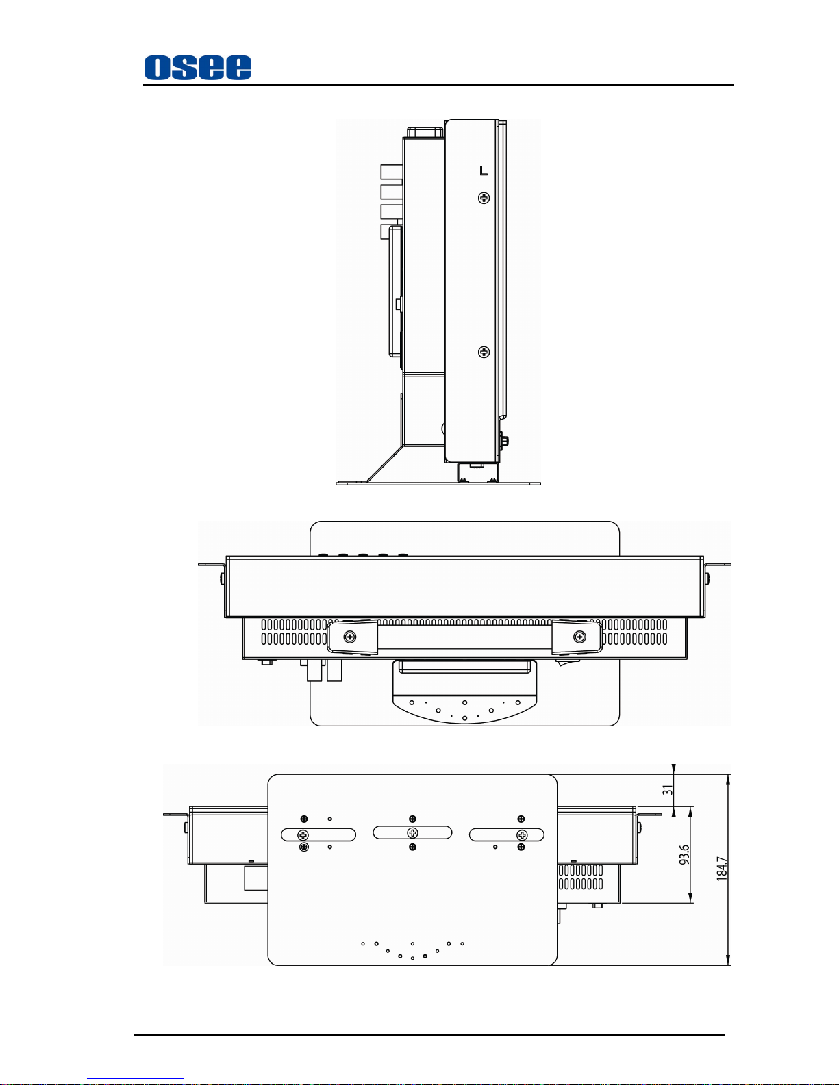
Side View (Unit: mm)
Top Side View (Unit: mm)
Bottom View
(Unit: mm)
Page 8
LMW-171 SERIES LCD MONITOR User Manual
—4—
Chapter 4 Operation
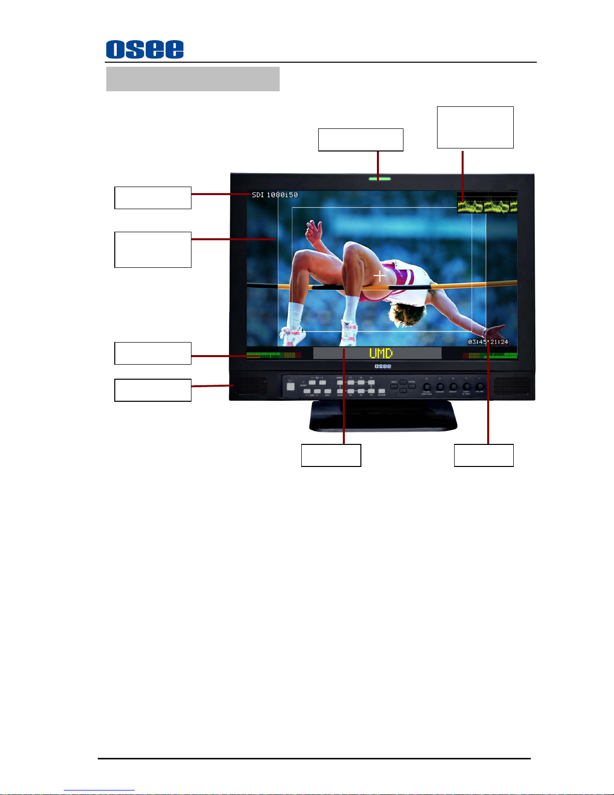
4.1 Status Display
) Tally Indicator:
It is used to check the status of the monitor by the color of the tally lamp.
(For more information, see the fourth page of “USER CONFIG” menu)
) Speakers
Output the audio which is selected by the input terminal select button.
) Wave form or vector graph
It is used to check the wave form or vector graph of the displaying signal picture.
Only used for SDI signal.
You can open and set the wave form or vector graph on the second page of “USER CONFIG” menu.
Signal format
Audio Meter
TALLY Indicator
Area & Safety
Marker
Speakers
Wave form or
vector graph
Time Code
UMD
Page 9
LMW-171 SERIES LCD MONITOR User Manual
—5—
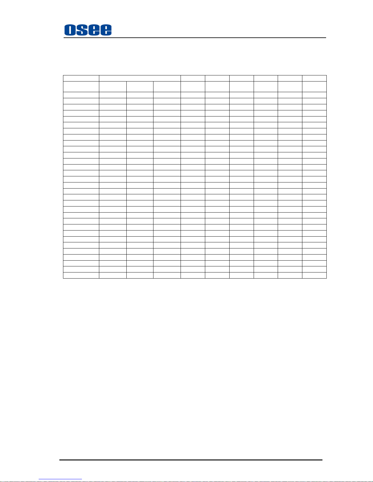
4.2 Input Signals
The following input signals are supported by the LMW-171 monitor:
Format SDI Video Y/C YPbPr HDMI DVI VGA
Device Type* LMW-171V LMW-171S LMW-171H
LMW-171 LMW-171 LMW-171 LMW-171 LMW-171 LMW-171
NTSC
/
/ /
YES YES
/
/ / /
PAL
/
/ /
YES YES
/
/ / /
SECAM
/
/ /
YES YES
/
/ / /
NTCS-4.43
/
/ /
YES YES
/
/ / /
PAL-M
/
/ /
YES YES
/
/ / /
480I60
/
YES YES
/
/
YES YES
/
/
576I50
/
YES YES
/
/
YES YES
/
/
480P60
/
/ / / /
YES YES
/
/
576P50
/
/ / / /
YES YES
/
/
720P24
/
/
YES
/
/ / / / /
720P25
/
/
YES
/
/ / / / /
720P30
/
/
YES
/
/ / / / /
720P50
/
/
YES
/
/
YES YES
/
/
720P60
/
/
YES
/
/
YES YES
/
/
1035I60
/
/
YES
/
/
YES YES
/
/
1080I60
/
/
YES
/
/
YES YES
/
/
1080I50
/
/
YES
/
/
YES YES
/
/
1080P24
/
/
YES
/
/
YES YES
/
/
1080P25
/
/
YES
/
/
YES YES
/
/
1080P30
/
/
YES
/
/
YES YES
/
/
1080P50
/
/ / / /
YES YES
/
/
1080P60
/
/ / / /
YES YES
/
/
1080SF24
/
/
YES
/
/
YES YES
/
/
VGA
/
/ / / / / /
YES YES
SVGA
/
/ / / / / /
YES YES
XGA
/
/ / / / / /
YES YES
SXGA
/
/ / / / / /
YES YES
UXGA
/
/ / / / / /
YES YES
WVGA
/
/ / / / / /
YES YES
WXGA
/
/ / / / / /
YES YES
WUXGA
/
/ / / / / /
YES YES
*: For ”Device Type”, LMW-171 includes LMW-171V, LMW-171S and LMW-171H.
“YES”: Adjustable/can be set; “\” : Not adjustable/cannot be set
Page 10
LMW-171 SERIES LCD MONITOR User Manual
—6—
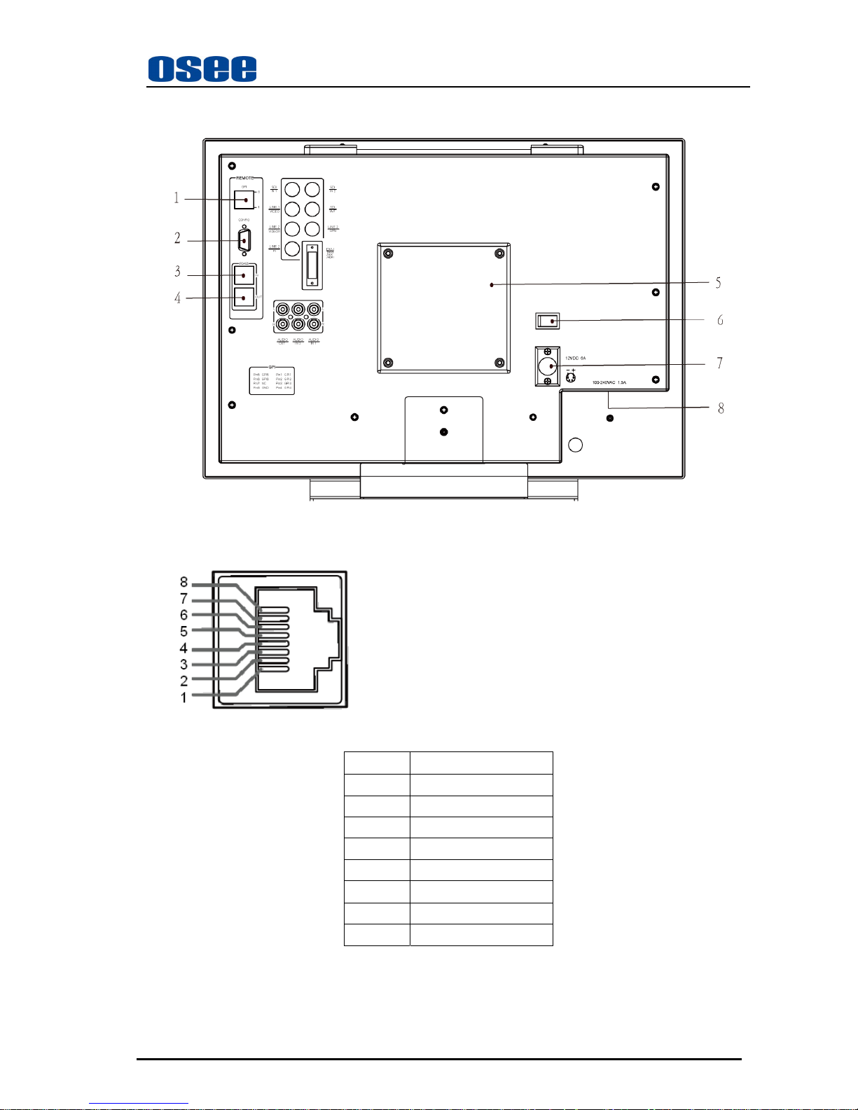
4.3 Rear Panel Terminals
A. Rear Panel
The specifications of terminals are as follows :
1 GPI :GPI Terminal
Female RJ-45 Receptacle
PIN Description
PIN 1 GPI1
PIN 2 GPI2
PIN 3 GPI3
PIN 4 GPI4
PIN 5 GPI5
PIN 6 GPI6
PIN 7 NC
PIN 8 GND
For the detailed information about GPI 1-GPI 6, see the fourth page of “USER CONFIG” menu.
2 CONFIG :Configuration Terminal
It is used to update the program only.
Page 11
LMW-171 SERIES LCD MONITOR User Manual
—7—
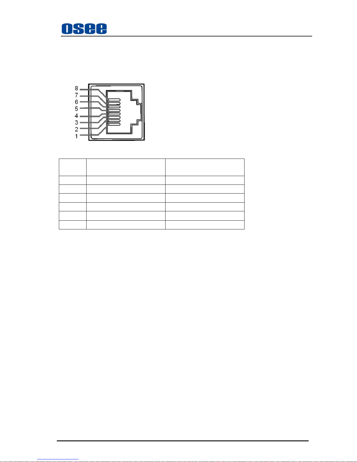
3 RS485 IN : RS485 IN Terminal ;
4 RS485 OUT : RS485 OUT Terminal ;
Female RJ-45 Receptacles
Pin No. RS485 IN Terminal Signal RS485 OUT Terminal Signal
1,2 GND GND
3 Tx- Tx4 Rx+ Rx+
5 Rx- Rx6 Tx+ Tx+
7,8 NC NC
5 Battery Mounter
Install the Battery Mounter and Battery here. The Battery Mounter and Battery are
optional
accesories, if necessary, please contact the manufacturer.
6
O/– (Power) Switch
The power is turned on or off.
The monitor is turned on by pressing side–.
7 Battery Input Connector
Connect the battery here.
Total Battery consumption: 12V DC, 6A.
8 Power Input Connector
T ot al pow er consumption: 100-240V AC, 1.5A.
Equipment power consumption: 60W.
A power source with the capacity of more than 80W is recommended.
Page 12
LMW-171 SERIES LCD MONITOR User Manual
—8—
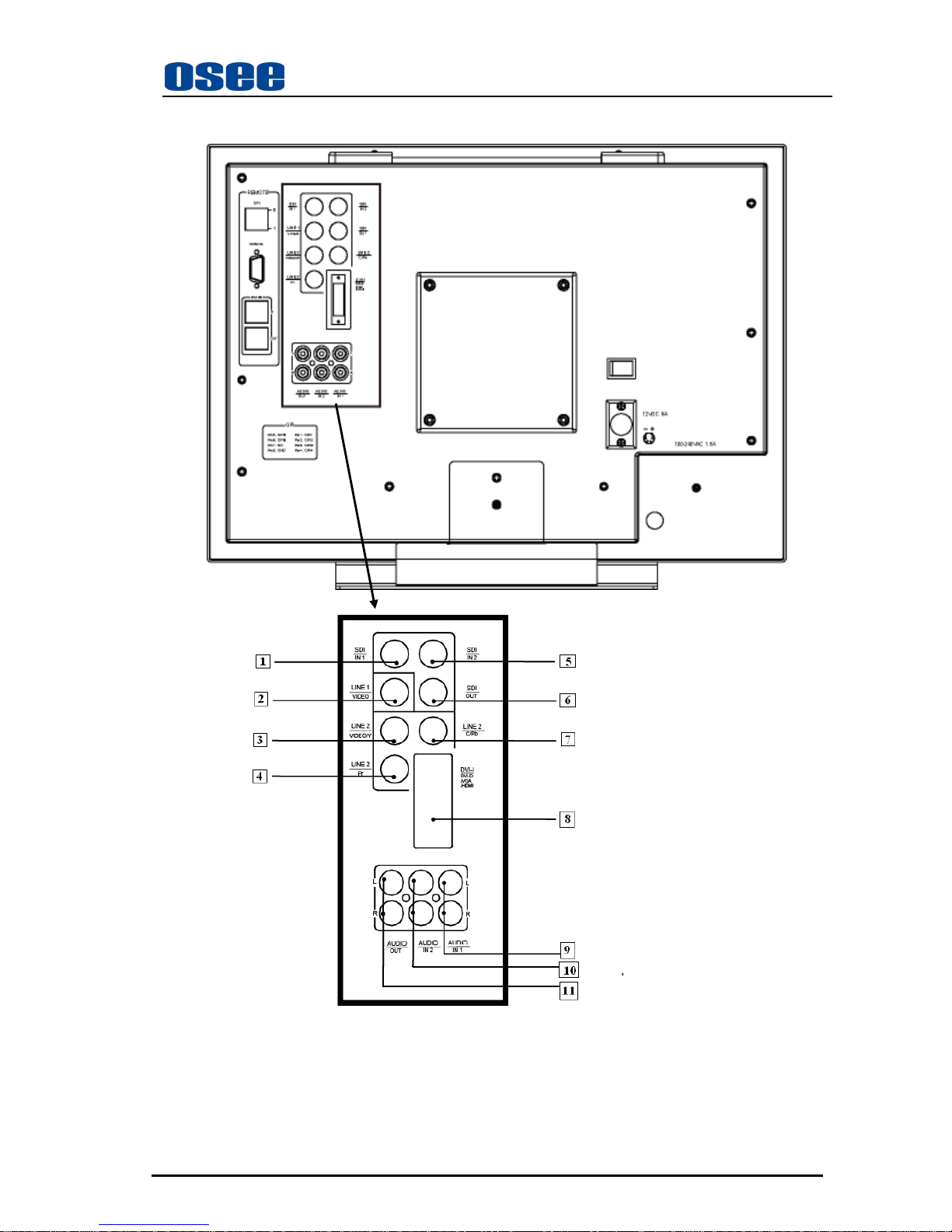
B. Audio and video connectors
Page 13
LMW-171 SERIES LCD MONITOR User Manual
—9—
The specifications of terminals are as follows :
SDI IN1 : SDI 1 Input Terminal
SD-SDI input signal which is in compliance with SMPTE259M and ITU-R BT656 standard.
SDI IN2 : SDI 2 Input Terminal
SD-SDI input signal which is in compliance with SMPTE259M and ITU-R BT656 standard.
SDI OUT : SDI Output Terminal
Output terminal for
selected SDI signal.
LINE1(VIDEO) : LINE 1 Input Terminal
Analog Composite Video Signal only.
LINE2 (VIDEO/Y): LINE 2 Input Terminal
Analog Composite Video input signal, or luminance (Y) signal of Y/C or YPbPr.
LINE2 (C/Pb): LINE 2 Input Terminal
Chroma (C) signal of Y/C or Pb(Blue) component of YPbPr .
LINE2 (Pr): LINE 2 Input Terminal
Pr (Red) component of YPbPr .
DVI-I(DVI-D/VGA/HDMI): DVI-I Input Terminal
DVI analog/digital. Requires adapter for VGA signals. Supports HDMI input signal.
AUDIO IN1: Analog Audio (IN1) T erminal
Input terminal for the analog audio signal.
L:left audio channel; R: right audio channel.
AUDIO IN2: Analog Audio (IN2) T erminal
Input terminal for the analog audio signal.
L:left audio channel; R: right audio channel.
AUDIO OUT: Analog Audio (OUT) T erminal
Outputs the audio signal which is selected by the input select button on the front panel.
L:left audio channel; R: right audio channel.
Page 14
LMW-171 SERIES LCD MONITOR User Manual
—10—
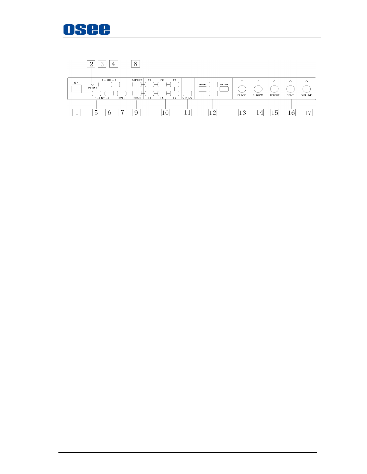
4.4 Location and Function of Control Buttons And Knobs On Front Panel
) (1)POWER : Power Standby / ON Switch
Press this switch to turn on the power of this unit or to set this unit in the standby mode(the
O/–
power switch on the rear panel is turned on).
Last settings recall with power.
Unlit: The monitor is completely off (mains switch is off).
Lights in Green: The monitor is on.
Lights in Red: The monitor is off (standby).
) (2)INHIBIT Indicator
Lights in orange when the key inhibit is set to ON.
(For more information, refer to the CONTROL menu of chapter 6).
) (3)SDI 1 Button/Lamp
Press the button to monitor the signal through the SDI1 terminal.
When the button is pressed, the SDI1 button lamp will light.
) (4)SDI 2 Button/Lamp
Press the button to monitor the signal through the SDI2 terminal.
When the button is pressed, the SDI2 button lamp will light.
) (5)LINE 1 Button/Lamp
Press the button to monitor the signal through the LINE 1 terminal.
When the button is pressed, the LINE 1 button lamp will light.
) (6)LINE 2 Button/Lamp
Press the button to monitor the input signal among VIDEO, Y/C, YPbPr. On the first page of
USER CONFIG menu, from “LINE 2 Input” item, you can set the input signal format which
should be monitored.
When the button is pressed, the LINE 2 button lamp will light.
) (7)DVI-I Button/Lamp
Press the button to monitor the input signal among VGA, DVI-D, and HDMI. On the first page
of USER CONFIG menu, from “DVI-I Input” item, you can set the input signal format which
should be monitored.
When the button is pressed, the DVI-I button lamp will light.
Page 15
LMW-171 SERIES LCD MONITOR User Manual
—11—
) (8)ASPECT Button/lamp
Press to set the aspect ratio of the picture, 4:3 or 16:9.
Scaled mode only effects for SD signal. For VGA, DVI and HD input signal, it is not valid and is
defaulted to 16:9 mode.
When the 4:3 mode is set, the button lamp lights and this status can be saved.
Note: For the available input signals of the ASPECT Button, see the description of “4.5 Input
Signals and Adjustable/setting Items” on this chapter.
) (9) SCAN Button/lamp
Press to change the scan size of the picture between normal (100% picture) and over (95%
picture). For VGA and DVI input signal, it is not valid and is defaulted to normal mode.
When the OVER mode is set, the button lamp lights and this status can be saved.
) (10)F1-F6 Button/lamp
F1-F6 can be used as quick-button.
You can turn the assigned function on or off.
When the button is pressed, the button lamp will light up. However, in some cases, the button
lamp will not light up.
When the assigned function is set to be “OFF” in the main menu and the corresponding
button is pressed, the button lamp will not light up.
In the quick-button function menu, when the character color is blue, the corresponding
button lamp will not light up.
You can assign each button function on the third page of USER CON FIG m enu.
9 When the current menu is not the main menu, press to call out the quick-button function
menu, the selected item displays in yellow. Execute the function which is selected in
USER CONFIG page 3 menu. If set operating, the button lamp will be lighted.
9 When the current menu is the main menu, press to execute the function which is selected
in USER CONFIG page 3 menu. If set operating, the button lamp will be lighted.
However, it can not call out the quick-button function menu.
The factory setting is as follows.
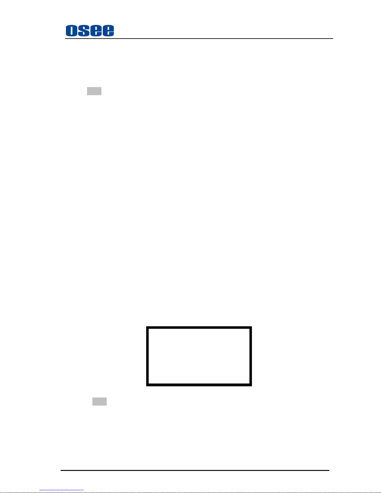
Tab. The Quick-button Function Menu
The quick-button function menu disappears automatically if it is not operated for 5 seconds.
Note:
For the quick-button function menu, the button function is valid if the character color is white.
The button function is not valid if the character color is blue.
) (11)STATUS: Status Indication Button
Press to display the status menu. When the main menu is on, this button is unavailable.
(For more information, see the STATUS menu of chapter 6).
F1 MARKER
F2 AUDIO METER
F3 H/V DALAY
F4 NATIVE
F5 AUTO ADJ
F6 BLUE ONLY
Page 16

LMW-171 SERIES LCD MONITOR User Manual
—12—
) (12)MENU, ENTER, UP, DOWN Button
Displays or sets the main menu.
Menu button:
Press to display the main menu, when the on-screen menu is not the main menu.
Press again to clear the main menu. (For more information, see the chapter 5)
Enter button:
Press to confirm a selected item on the menu, when the on-screen menu is the main menu .
(For more information, see the chapter 5)
When the on-screen menu is not the main menu and the button is pressed, the
quick-button function menu is displayed. Press again to clear the quick-button function
menu.
Or, if the current menu is quick-button function menu, press to clear it.
UP, DOWN Button:
Press to select the items and setting values. (For more information, see the chapter 5)
) (13) PHASE Knob
Displays and adjusts the picture hue value.
1. Press this knob to display the picture hue value.
2. Adjust the knob clockwise, the value increases. A dj ust t he kn ob co unter-clockwise, the value
decreases. The adjusted value will be saved.
3. When the current value of hue is not the default setting value (50), the indicator lamp above the
knob will light. Return the value to the default settings (50), the indicator goes out.
4. If the adjustment function is enabled and left unattended, the menu will automatically disappear
after 3 seconds.
5. Adjustment values range: 0-100.
Note: Only for the input signal (VIDEO:NTSC and Y/C:NTSC), the PHASE menu is available.
) ( 14) CHROMA Knob
Displays and adjusts the picture color saturation value:
1. Press this knob to open the picture color saturation menu.
2. Adjust the knob clockwise, the value increases. Adjust the knob count er-clockwise, the value
decreases. The adjusted value will be saved.
3. If left unattended, the menu automatically disappears after 3 seconds.
4. When the current value of saturation is not the default setting value (50), the indicator lamp
above the knob will light. Return the value to the default settings (50), the indicator goes out.
5. Adjustment values range: 0-100.
Note: When the input signals are VGA or DVI-D, this knob is not available.
) (15) BRIGHT Knob
Displays and adjusts the picture brightness value:
1. Press this knob to display the picture brightness menu.
2. Adjust the knob clockwise, the value increases. Adjust the knob co unter-clockwise, the value
decreases. The adjusted value will be saved.
3. If the adjustment function is enabled and left unattended, the menu automatically disappears after
3 seconds.
4. When the current value of saturation is not the default setting value (50), the indicator lamp
above the knob will light. Return the value to the default settings (50), the indicator goes out.
5. Adjustment values range: 0-100.
Page 17
LMW-171 SERIES LCD MONITOR User Manual
—13—
) ( 16) CONT Knob
Displays and adjusts the picture contrast value:
1. Press this knob to display the picture contrast value.
2. Adjust the knob clockwise, the value increases. Adjust the knob count er-clockwise, the value
decreases. The adjusted value will be saved.
3. If the adjustment function is enabled and left unattended, the menu automatically disappears after
3 seconds.
4. When the current value of saturation is not the default setting value (50), the indicator lamp
above the knob will light. Return the value to the default settings (50), the indicator goes out.
5. Adjustment values range: 0-100.
) ( 17) V olum e Knob
Displays and adjusts the speaker volume value; and enables/disables speaker mute function:
1. Press this knob to toggle mute on/off. If toggled to the mute function, the indicator lamp above
the knob will light. At the same time, the icon“MUTE”will display on the right bottom of the
screen. To cancel this function, press VOLUME knob again. At the same time, the indicator
lamp above the knob will go out and the icon“MUTE”will disappear.
2. Turning the knob will toggle to the speaker volume function and adjust the speaker volume value.
Adjust the knob clockwise, the value increases. Adjust the knob counter-clockw ise, the value
decreases. The adjusted value will be saved. If the adjustment function is enabled and left
unattended, the menu automatically disappears after 3 seconds.
3. Volume adjustment range is 0-30. ( 0: stand for close the audio but not mute mode)The default
value is 15.
Note: For VGA or DVI-D input signal, there is no audio.
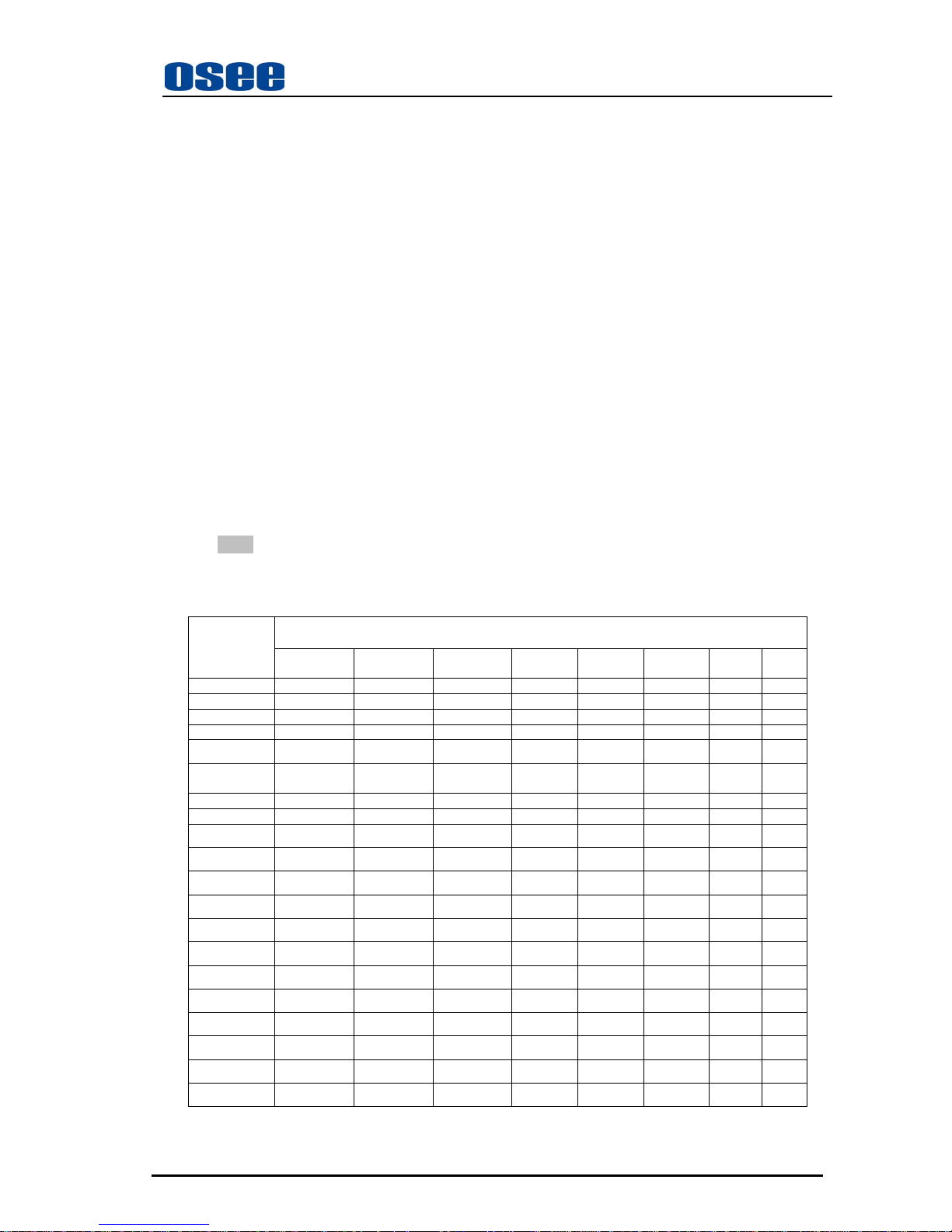
4.5 Input Signals and Adjustable/setting Items
Input signal
Item
Video ;
Y/C
YPbPr SD
YPbPr HD SDI SD SDI HD HDMI DVI VGA
Contrast YES YES YES YES YES YES YES YES
Bright YES YES YES YES YES YES YES YES
Chroma YES YES YES YES YES YES \ \
Phase NTCS \ \ \ \ \ \ \
NTSC Setup NTSC
\
\ \ \ \ \ \
Compo
Level
SMPTE 480I60 SMPTE SMPTE
SMPTE SMPTE \ \
Color Temp YES YES YES YES YES YES YES YES
SCAN YES YES YES YES YES YES FULL FULL
ASPECT YES YES \ YES \ SD/YES
\
\
MARKER YES YES YES YES YES YES
\
\
BLUE ONLY YES YES YES YES YES YES
\
\
MONO YES YES YES YES YES YES
\
\
H/V DELAY
\
\ \
YES YES
\
\ \
DOT PHASE
\
\ \ \ \ \ \
YES
H Position
\
\ \ \ \ \ \
YES
V Position
\
\ \ \ \ \ \
YES
Audio Ext Ext Ext Ext/Ebd Ext/Ebd Ext/Ebd
\
\
Time Code \ \ \ YES YES \
\
\
UMD YES YES YES YES YES YES
\
\
Audio Meter YES YES YES YES YES YES
\
\
“YES”: Adjustable/can be set; “\” : Not adjustable/cannot be set
Page 18
LMW-171 SERIES LCD MONITOR User Manual
—14—
Chapter 5 Menu Operation Guide
5.1 Selecting the Menu Language
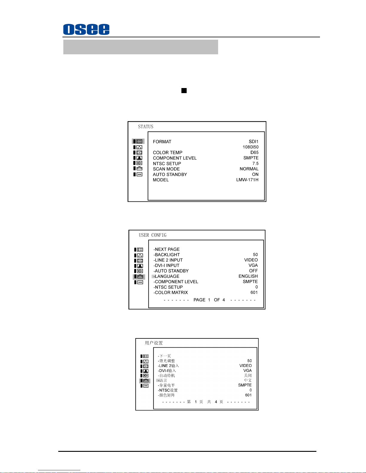
You can select one of two languages (English, Chinese) for displaying the menu and other on-screen
displays. ”English” is selected in the default setting.
The current settings are displayed in place of the
marks on the illustrations of the menu screen.
1. Turn on the unit.
2. Press MENU button.
The menu appears.
The menu presently selected is shown in yellow.
3. Press ∧(up)or ∨(down) button to select the first page of USE CONFIG menu, then press the
ENTER button. The setting items (icons) in the selected menu are displayed in yellow.
4. Press ∧(up)or ∨(down) button to select “LANGUAGE,” then press the ENTER button. The
selected item is displayed in yellow.
5. Press ∧(up)or ∨(down) button to select a language, then press the ENTER button. The menu
changes to the selected language.
To clear the menu:
Press the MENU button.
The menu disappears automatically if none of the buttons is operated for one minute.
Page 19
LMW-171 SERIES LCD MONITOR User Manual
—15—
5.2 Using the Menu
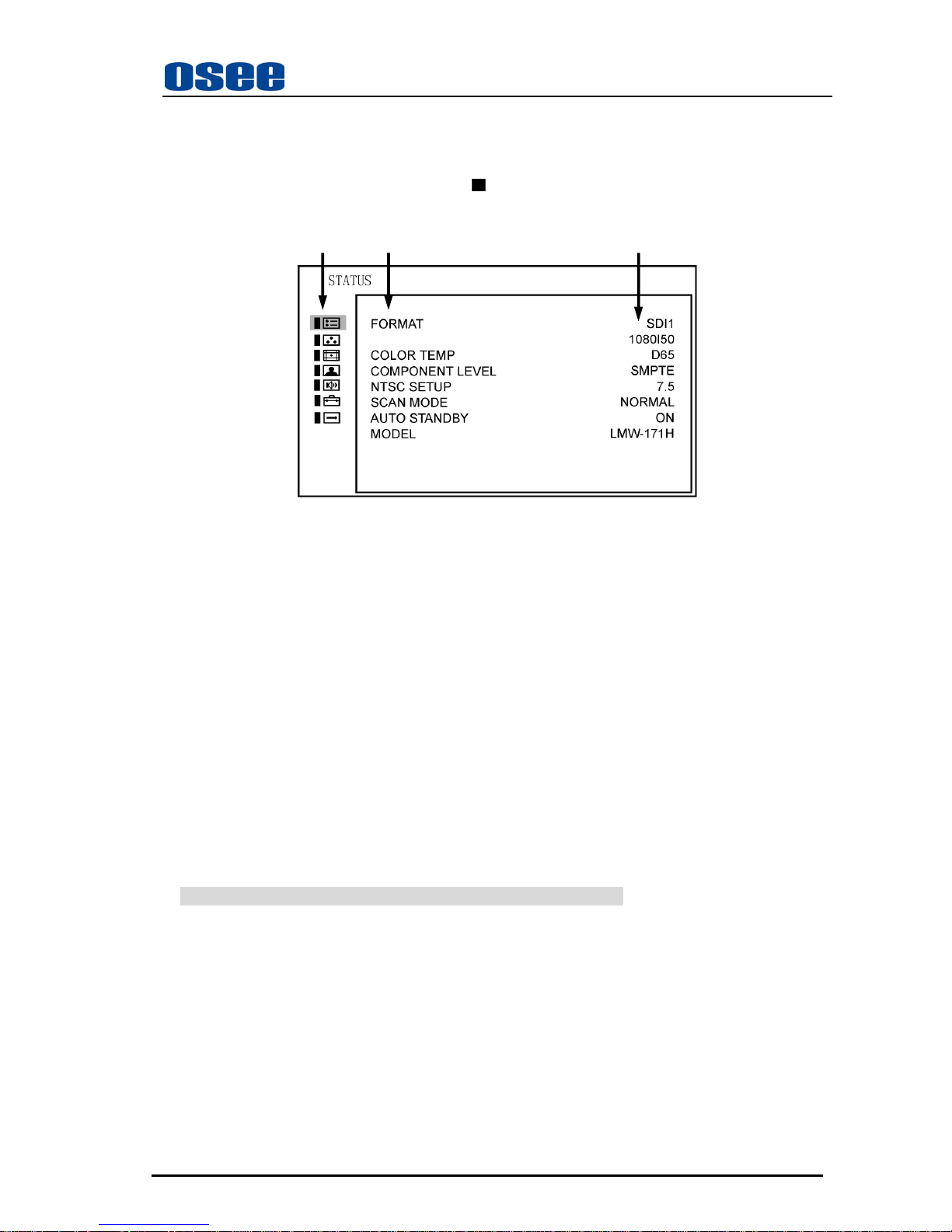
The unit is equipped with an on-screen menu for making various adjustments and settings such as STATUS,
COLOR TEMP, MARKER, etc.
The current settings are displayed in place of the
marks on the illustrations of the menu screen.
(1) (2) (3)
(1): Main Menu Item Select Field
Pressing Up/down key can select the sub menu.
Pressing Enter key can enter into the control item.
Pressing Menu key can quit the main menu.
(2): Sub Menu Item Select Field
Pressing Up/down key can select the control item.
Pressing Enter key can enter into the sub adjustable item.
Pressing Menu key can return to main menu.
(3): Control Item Select Field
Pressing Up/down key can adjust the item value, if the item is adjustable.
Pressing Enter key can save and quit current item. The item in white means the value is adjustable, the
item in blue means the value is not adjustable.
Pressing Menu key can quit current item, but can not save adjusted item.
While the menu is on, it can refresh the menu, if the input changed
To clear the menu:
Press the MENU button.
The menu disappears automatically if none of the buttons is operated for one minute.
Page 20
LMW-171 SERIES LCD MONITOR User Manual
—16—
Chapter 6 LMW-171 Series LCD Monitor Menu Structure
6.1 Main Menu
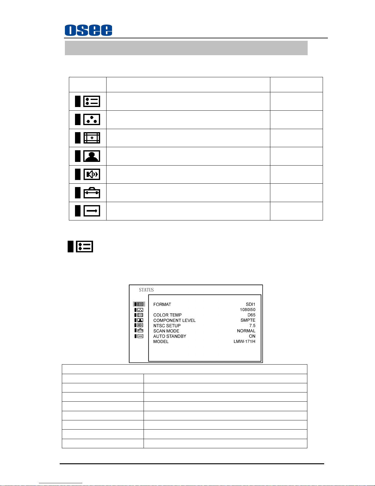
The screen menu of this monitor consists of the following items.
[Label] [Main Menu Item] [Sub Menu]
STATUS 1
COLOR TEMP 1
MARKER 1
VIDEO CONFIG 1
AUDIO CONFIG 3
USER CONFIG 5
CONTROL 1
6.2 Adjusting and Changing the Settings
STATUS
The STATUS menu is used to display the current status of the unit. The following items are displayed.
For the video inputs include SDI1, SDI2, Line1, Line2 or DVI-I (HDMI input only), the following
items are displayed.
STATUS
FORMAT SDI1
1080I50
COLOR TEMP D65
COMPONENT LEVEL SMPTE
NTSC SETUP 7.5
SCAN MODE NORMAL
AUTO STANDBY ON
MODEL* LMW-171H
Page 21
LMW-171 SERIES LCD MONITOR User Manual
—17—
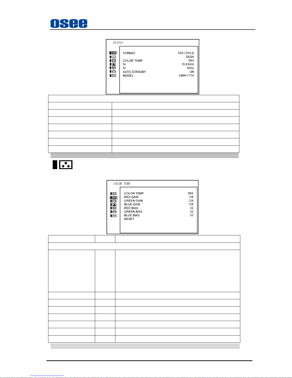
For the DVI/VGA input, the following items are displayed.
STATUS
FORMAT DVI-I:DVI-D
SXGA
COLOR TEMP D65
fH 15.63kHz
fV 60Hz
AUTO STANDBY ON
MODEL* LMW171-H
* For Model, it will display LMW-171H or LMW-171S or LMW-171V, depending on the unit model.
COLOR TEMP
The COLOR TEMP menu is used for adjusting the picture white balance.
Sub Menu Settings Explanation
COLOR TEMP
-COLOR TEMP D65 Used to select the color temperature that will become the basis
for adjustments:
y <D93> around 9300K
y <D65> around 6500K
y <D56> around 5600K
y <USER>
-RED GAIN 0-255 <0-60>, factory preset settings: 128
-GREEN GAIN 0-255 <0-60>, factory preset settings: 128
-BLUE GAIN 0-255 <0-60>, factory preset settings: 128
-RED BIAS 0-64 <0-60>, factory preset settings: 32
-GREEN BIAS 0-64 <0-60>, factory preset settings: 32
-BLUE BIAS 0-64 <0-60>, factory preset settings: 32
-RESET This returns the GAIN and BIAS settings to the factory presets
When adjusting the GAIN and BIAS settings, the item display moves to the middle part of the screen.
Page 22
LMW-171 SERIES LCD MONITOR User Manual
—18—
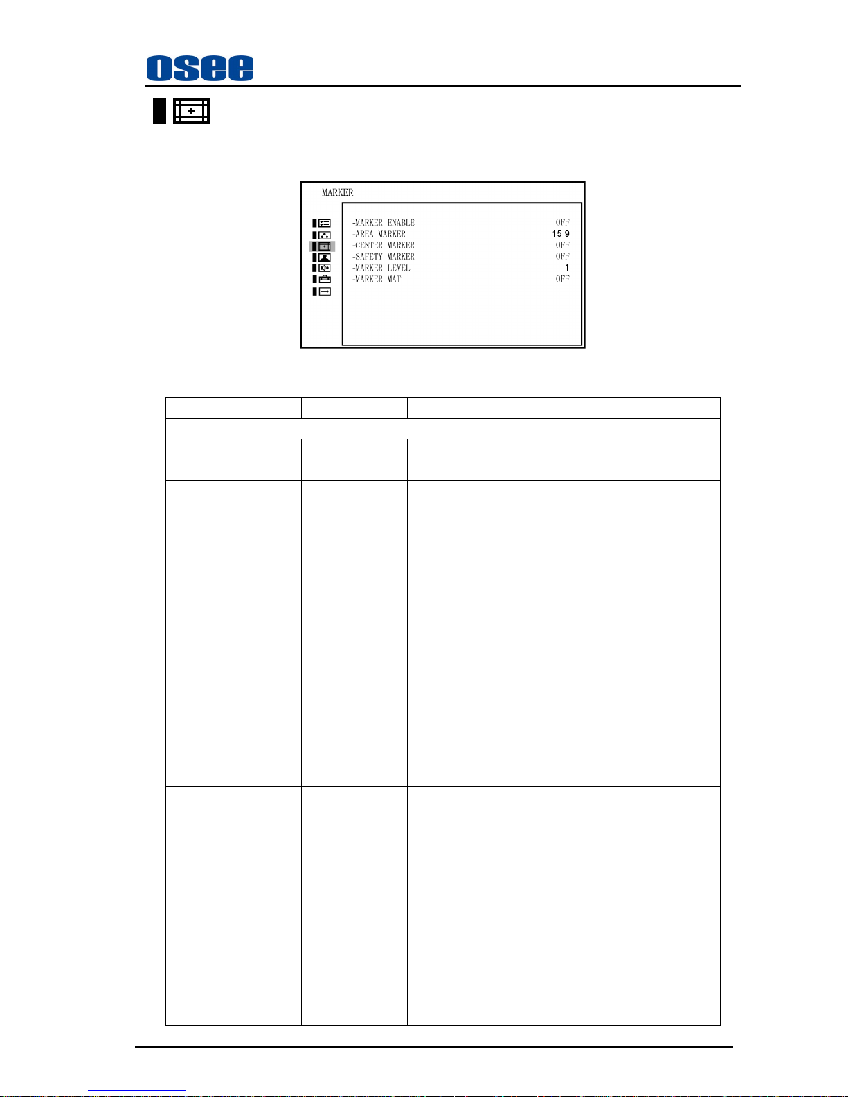
MARKER
The MARKER menu is used for setting the marker.
Sub Menu Settings Explanation
MARKER
-MARKER ENABLE ON <ON> marker displayed
<OFF> marker not displayed
-AREA MARKER 15:9 Selects the area marker aspect ratio according to the
display aspect,
) For display aspect ratio is 16:9
<OFF>
<4:3> vertical
<15:9> vertical
<14:9>vertical
<13:9> vertical
<1.85:1> horizontal
<2.35:1> horizontal
) For display aspect ratio is 4:3
<OFF>
<16:9>
-CENTER MARKER ON <ON> marker displayed
<OFF> marker not displayed
-SAFETY MARKER OFF Setting the picture safe area size marker for the aspect
ratio determined by the button which the aspect
function is assigned.
(According to display aspect and SCAN control)
y <OFF>
y <80%>
y <85%>
y <88%>
y <90%>
y <93%>
y <95%>
Page 23
LMW-171 SERIES LCD MONITOR User Manual
—19—
Sub Menu Settings Explanation
-MARKER LEVEL <1> Sets the luminance to display safety, center and area
marker line.
y <1>: 50% white level
y <2>: 75% white level
y <3>: 100% white level
-MARKER MAT <OFF> Sets the area marker mat transparency.
y <OFF> : Normal background, only use line for area
marker edge indication
y <HALF> : 50% background brightness
y <BLACK> : Black
16:9 and 4:3 area marker settings are stored separately.
Use 16:9 setting if display aspect is 16:9; Use 4:3 setting if display aspect is 4:3
Marker is disabled when SCAN is NATIVE, input is DVI or VGA.
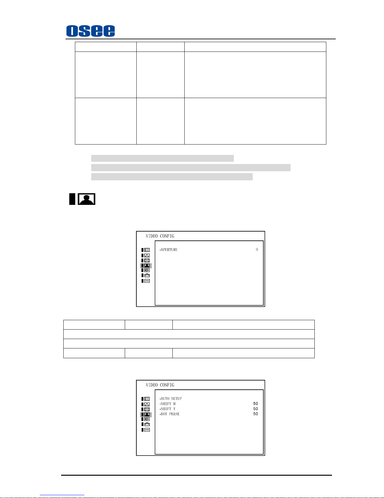
VIDEO CONFIG
For the video inputs include SDI1, SDI2, Line1, Line2 or DVI-I (HDMI input only), the following
items are displayed.
Sub Menu Settings Explanation
VIDEO CONFIG
PICTURE CONTROL
-APERTURE 0 <0-100>
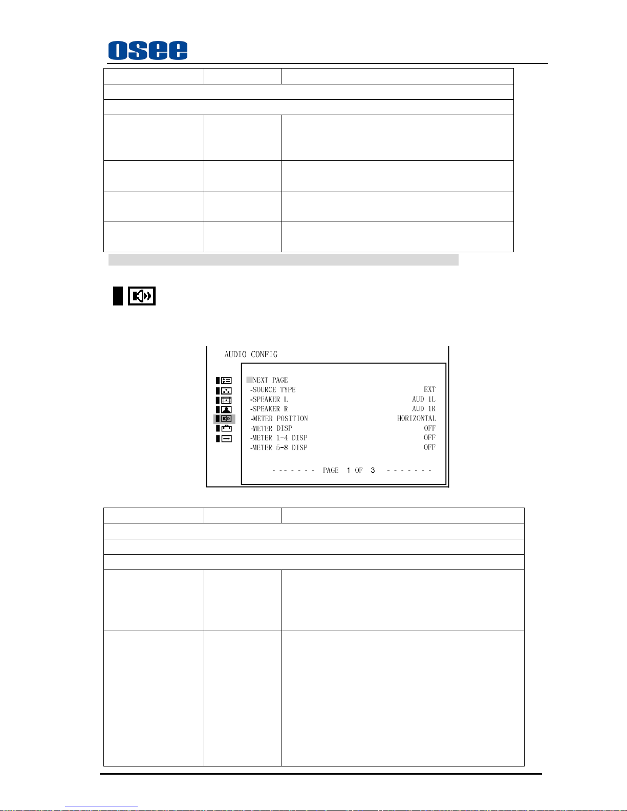
For the DVI/VGA input, the following items are displayed.
Page 24
LMW-171 SERIES LCD MONITOR User Manual
—20—
Sub Menu Settings Explanation
VIDEO CONFIG
PICTURE CONTROL
-AUTO SETUP1 Automatic Pixel Adjustment, press to adjust the
picture automatically to maximize clarity and correct
H/V position for the VGA input signal
-SHIFT H 50 Adjusts the horizontal position of the picture
<0-100>
-SHIFT V 50 Adjusts the vertical position of the picture
<0-100>
-DOT PHASE 50 Adjusts the dot phase
<0-100>
1. For “AUTO SETUP” menu, it is valid for VGA input, but not valid for DVI input.
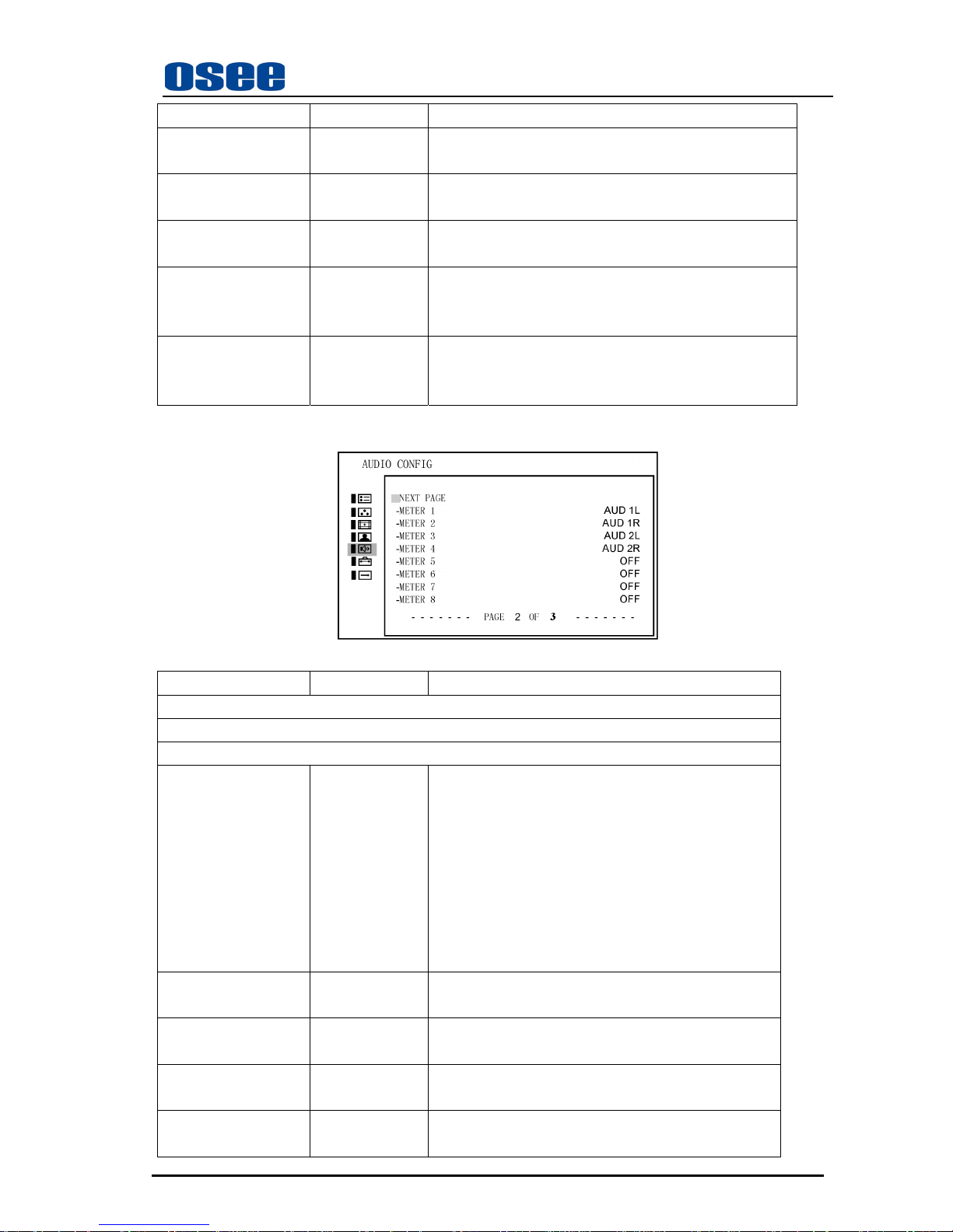
AUDIO CONFIG
For the video inputs include SDI1, SDI2, Line1, Line2 or DVI-I (HDMI input only), the following
items are displayed.
Sub Menu Settings Explanation
AUDIO CONFIG 1/3
GENERAL SETUP
-NEXT PAGE
-SOURCE TYPE EXT Used to select the audio source type
<EXT>
<EBD> can be selected only for SDI or HDMI input
<NONE>
-SPEAKER L AUD 1L
(EBD CH1)
Select the audio channel to the left speaker based on the
selected audio source type
) <OFF>
) If SOURCE TYPE is AUD
<AUD 1L, AUD 1R, AUD 2L, AUD 2R>
) If SOURCE TYPE is EBD and SDI input
<EBD CH1 – EBD CH16>
) If SOURCE TYPE is EBD and HDMI input
<EBD CH1 – EBD CH2>
Page 25
LMW-171 SERIES LCD MONITOR User Manual
—21—
Sub Menu Settings Explanation
-SPEAKER R AUD 1 R
(EBD CH2)
The same as above
-METER POSITION HORIZONTAL <HORIZONTAL>
<VERTICAL>
-METER DISP OFF <OFF>
<ON>
-METER 1-4 DISP OFF <OFF>
<1-2>
<1-4>
-METER 5-8 DISP OFF <OFF>
<5-6>
<5-8>
Press ∧(up)or ∨(down) button to select “NEXT PAGE” item, then press Enter button to display the
next page menu as follows.
Sub Menu Settings Explanation
AUDIO CONFIG 2/3
METER SOURCE
-NEXT PAGE
-METER 1 AUD 1L
(EBD CH1)
Used to assign the audio channel for meter display
based on the selected audio source type
) <OFF>
) If SOURCE TYPE is EXT
<AUD 1L, AUD 1R, AUD 2L, AUD 2R>
) If SOURCE TYPE is EBD and SDI input
<EBD CH1 – EBD CH16>
) If SOURCE TYPE is EBD and HDMI input
<EBD CH1 – EBD CH2>
-METER 2 AUD 1R
(EBD CH2)
The same as above
-METER 3 AUD 2L
(EBD CH3)
The same as above
-METER 4 AUD 2R
(EBD CH4)
The same as above
-METER 5 OFF
(EBD CH5)
The same as above
Page 26
LMW-171 SERIES LCD MONITOR User Manual
—22—
Sub Menu Settings Explanation
-METER 6 OFF
(EBD CH6)
The same as above
-METER 7 OFF
(EBD CH7)
The same as above
-METER 8 OFF
(EBD CH8)
The same as above
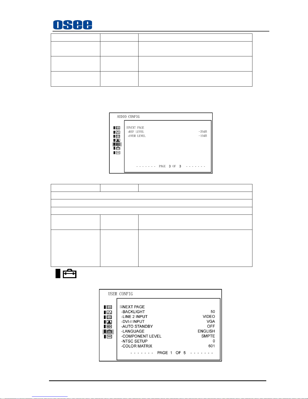
Press ∧(up)or ∨(down) button to select “NEXT PAGE” item, then press Enter button to display the
next page menu as follows. Select “NEXT PAGE” item in the following menu, it will return to display the
first page menu of “AUDIO CONFIG”.
Sub Menu Settings Explanation
AUDIO CONFIG 3/3
LEVEL SETUP
-NEXT PAGE
-REF LEVEL -20dB <-20dB>
<-18dB>
-OVER LEVEL -10dB <-10dB>
<-8dB >
<-6dB >
<-4dB >
<-2dB >
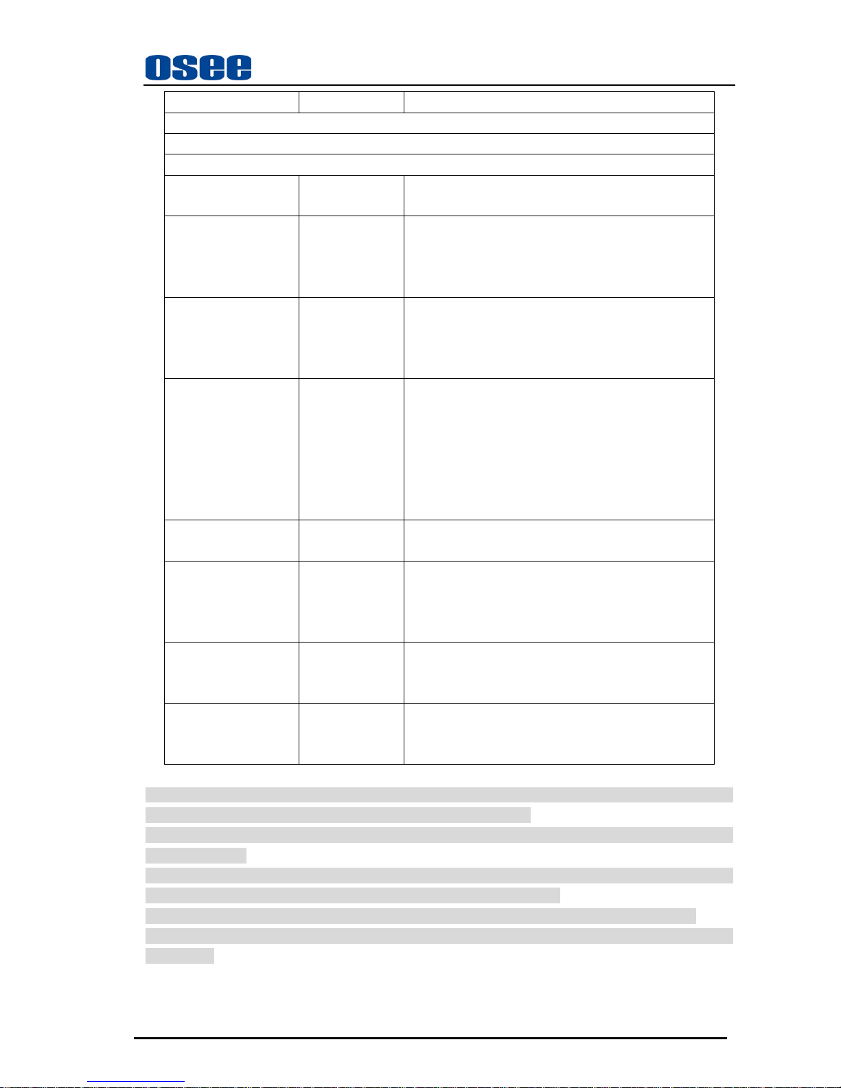
USER CONFIG
The USER CONFIG menu is used for setting the LINE 2 input, DVI-I input, language, etc.
Page 27
LMW-171 SERIES LCD MONITOR User Manual
—23—
Sub Menu Settings Explanation
USER CONFIG 1/5
SYSTEM SETUP
-NEXT PAGE
-BACKLIGHT1 50 Adjusts the backlight
<0 ... 100>
-LINE 2 INPUT VIDOE Selects the LINE 2 input type
y <VIDEO>
y <Y/C>
y <YPbPr>
-DVI-I INPUT2 VGA Selects the DVI-I input type
y <VGA>
y <DVI-D>
y <HDMI>
-AUTO STANDBY OFF Sets the power saving mode
turn on/off PANEL (include backlight and panel
power supply, signal to panel)
y <ON> the monitor goes into power saving mode if
no signal is input for about one minute
y <OFF> the monitor keeps power on regardless input
signal status
-LANGUAGE ENGLISH <ENGLISH>: English
<中文>: Chinese
-COMPONENT
LEVEL
3
SMPTE Only for 480i60 component input, refer to table 1
y <SMPTE> for 100/0/100/0 signal
y <BETA0> for 100/0/75/0 signal
y <BETA7.5> for 100/7.5/75/7.5 signal
-NTSC SETUP4 0 Only for NTSC signal
y <0> for Japan
y <7.5> for North America
-COLOR MATRIX5 601 Applied to 480/60I or 480/60P
y <601>
y <709>
1. Backlight Intensity is a fac tor in the operating life of th e backlight. Reducing the intens ity will lengthen
the backlight life whilst maximum intensity will decrease backlight life.
2. NOTES: the displaying signal, switching from HDMI to DVI-D or from DVI-D to HDMI, may not
normally display.
3. Component level only effects for YPbPr 480i input signal, and it will be set in blue color when other
signal. Component level always uses SMPTE except for 480i60 input signal .
4. NTSC SETUP only effects for NTSC input signal, and it will be set in blue color when other signal.
5. COLOR MATRIX is only applied to 480i/60 or 480/60p input signal, and it will be set in blue color when
other signal.
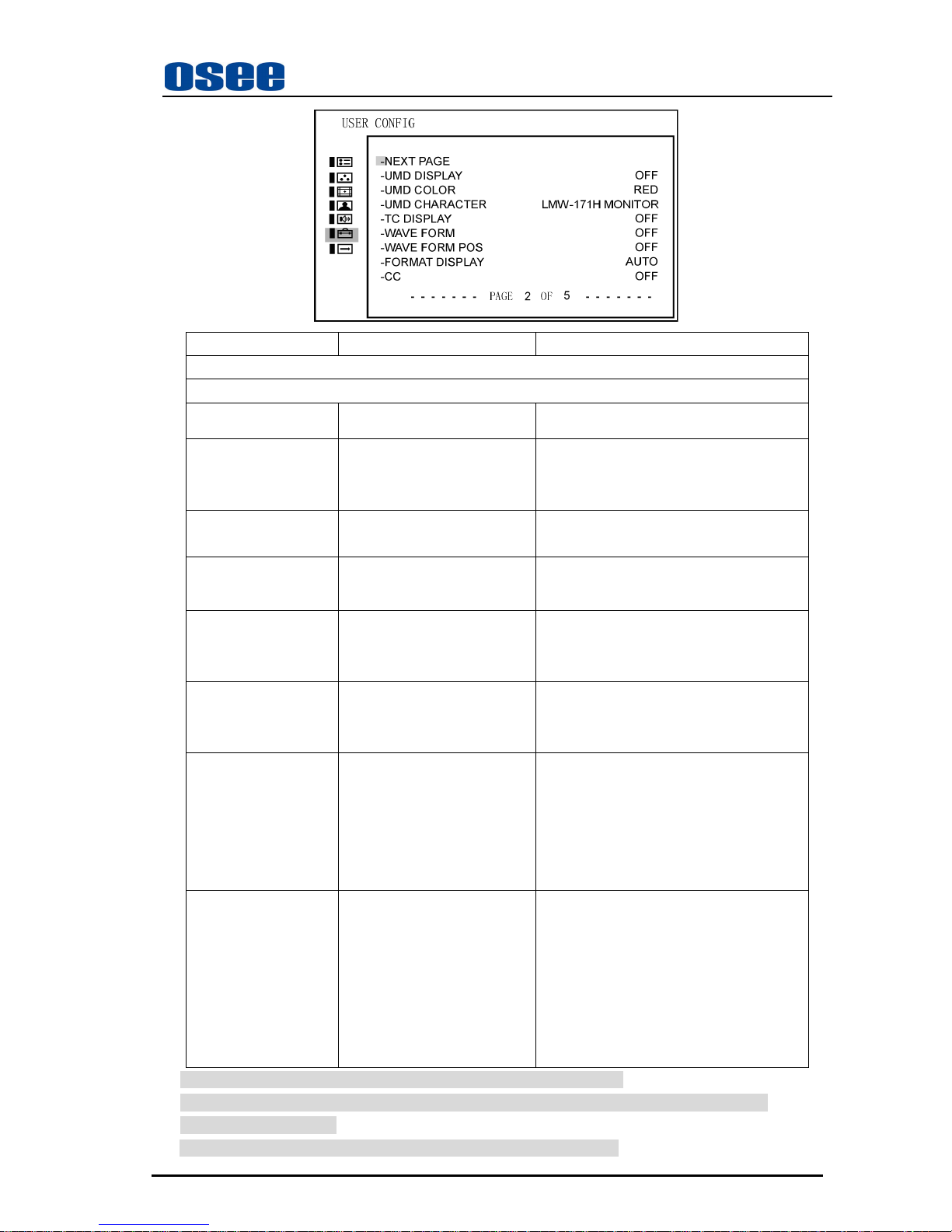
Press ∧ (up) or ∨ (down) button to select “NEXT PAGE” item, then press Enter button to display
the next page menu as follows.
Page 28
LMW-171 SERIES LCD MONITOR User Manual
—24—
Sub Menu Settings Explanation
USER CONFIG 2/5
-NEXT PAGE
-UMD DISPLAY OFF
<ON>
<OFF>
-UMD COLOR RED
<RED>
<GREEN>
<YELLOW>
<WHITE>
-UMD
CHARACTER
1
LMW-171H MONITOR 16 characters
-TC DISPLAY OFF
<ON>
<OFF>
Display --:--:--:-- if no TC in ANC
-WAVE FORM 2 OFF
<OFF>
<WAVE>:Waveform
<VECT75> Vector graph
<VECT100> Vector graph
-WAVE FORM POS 2 TOP RIGHT
<BOT LEFT>
<BOT RIGHT>
<TOP LEFT>
<TOP RIGHT>
-FORMAT DISPLAY AUTO y <ON> the format and scan mode are
always displayed
y <AUTO> the format and scan mode are
displayed for about 10 seconds when
the input of the signal starts
y <OFF> the display is hidden
-CC 3 OFF
<OFF>
<CC1>
<CC2>
<CC3>
<CC4>
<TEXT1>
<TEXT2>
<TEXT3>
<TEXT4>
<XDS>
1. The default of “UMD CHARACTER” depends on the type of device.
2. Wave form is used to check the wave form and vector graph of the displaying signal picture.
Only used for SDI signal.
3. CC only can be used for VIDEO: NTSC and Y/C: NTSC input signal.
Page 29
LMW-171 SERIES LCD MONITOR User Manual
—25—
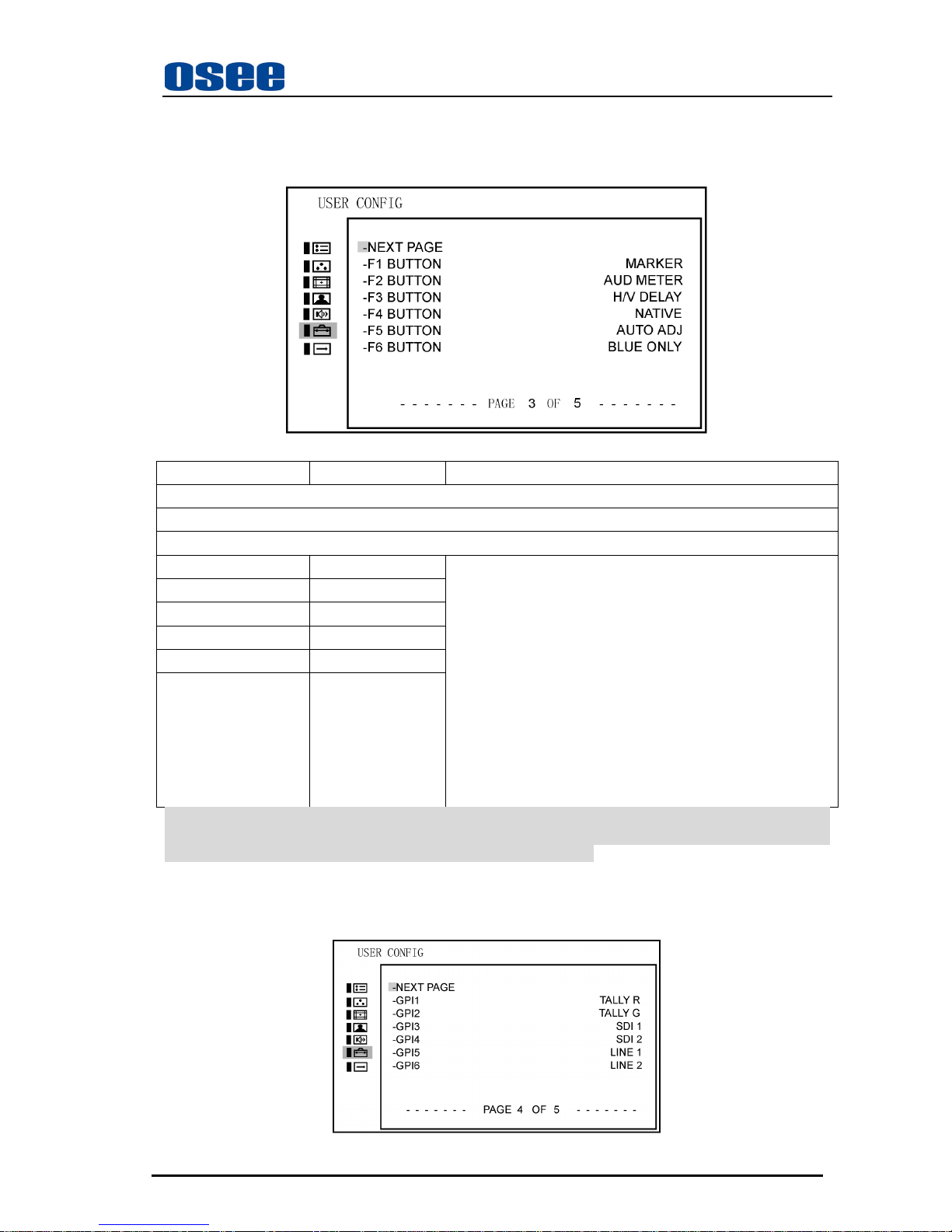
Press ∧(up)or ∨(down) button to select “NEXT PAGE” item, then press Enter button to display the
next page menu as follows.
Sub Menu Settings Explanation
USER CONFIG 3/5
FUNCTION BUTTON SETUP
-NEXT PAGE
-F1 BUTTON MARKER
-F2 BUTTON AUDIO METER
-F3 BUTTON H/V DELAY
-F4 BUTTON NATIVE
-F5 BUTTON AUTO ADJUST
-F6 BUTTON BLUE ONLY
F1- F6 button functions can be set as follows:
y <MARKER>: Control all MARKER ON-OFF-ON
y <AUDIO METER>: Control all audio meter display,
ON-OFF-ON
y <WAVEFORM>: OFF-WAVE-VECT75-VECT100-OFF
y <H/V DELAY>: OFF-H-V-H/V-OFF
y <AUTO ADJUST>: Press to initial auto adjustment
y <NATIVE>: [ NATIVE]-OFF
y <BLUE ONLY>: BLUE-NORMAL-BLUE
y <MONO>: MONO-NORMAL-MONO
y <UNDEF>: no settings
Note: When the SCAN MODE is set to < NATIVE> and the input signal is 1080P or 1080i, repeatedly
press the SCAN button, the position of picture will display in the loop way of <center>-<TOP LEFT
> - < TOP RIGHT > - < BOT RIGHT >- < BOT LEFT >-<center>
Press ∧(up)or ∨(down) button to select “NEXT PAGE” item, then press Enter button to display the
next page menu as follows.
Page 30
LMW-171 SERIES LCD MONITOR User Manual
—26—
Sub Menu Settings Explanation
USER CONFIG 4/5
GPI SETUP
-NEXT PAGE
-GPI1 TALLY R y <NONE>
y <TALLY R>
y <TALLY G>
y <SDI 1>
y <SDI 2>
y <LINE 1>
y <LINE 2>
y <DVI-I>
y <H/V DELAY>
y <MONO>
y <BLUE ONLY>
y <NORMAL SCAN>
y <OVER SCAN>
y <NATIVE>
y <ASPECT 16:9>
y <ASPECT 4:3>
y <MARKER >
-GPI2 TALLY G The same as above
-GPI3 SDI 1 The same as above
-GPI4 SDI 2 The same as above
-GPI5 LINE 1 The same as above
-GPI6 LINE 2 The same as above
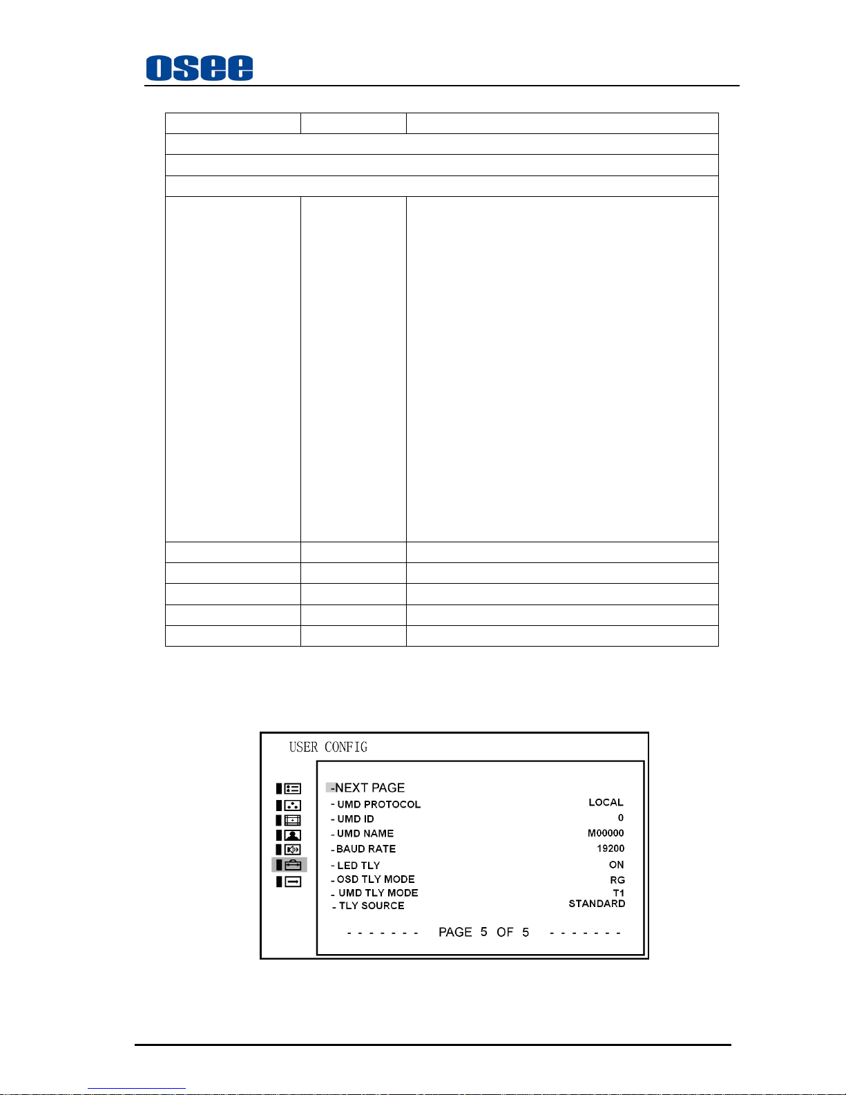
Press ∧(up)or ∨(down) button to select “NEXT PAGE” item, then press Enter button to display the
next page menu as follows. Select “NEXT PAGE” item in the following menu, it will return to display the
first page menu of “USER CONFIG”.
Page 31

LMW-171 SERIES LCD MONITOR User Manual
—27—
Sub Menu Settings Explanation
USER CONFIG 5/5
-NEXT PAGE
-UMD PROTOCAL LOCAL
LOCAL/TSL3.1/TSL4.0/IMAGE VIDEO
y LOCAL: Use UMD setting (USER CONFIG
2/5) to control the UMD.
y TSL3.1: Use the TSLV3.1 protocol setting to
control the UMD from a TSL tally controller.
y TSL4.0: Use the TSLV4.0 protocol setting to
control the UMD from a TSL tally controller.
y IMAGE VIDEO: Use the Image video
protocol setting to control the UMD from an
Image Video tally controller (TSL-1510).
-UMD ID 0
0 – 255
The UMD ID will determine which DISPLAY will
be show.
-UMD NAME(S/N) M00000
16 Characters for Option
y Use this setting to assign a name to the
Remote Display.
y Press ENTER to edit the UMD name.
y Use UP and DOWN to select characters.
y Press ENTER to go to next cursor. Press
MENU to exit editor.
-BAUD RATE 19200
9600/19200/38400
-LED TL Y OFF
ON/OFF
Set the LED Tally ON or OFF.
-OSD TL Y MODE OFF
RG/GR/RGY/OFF
Use this setting to choose OSD Tally Mode.
Only the TALLY SOURCE is STANDARD or
STANDARD+IV422 can make the setting be
available.
-UMD TL Y MODE T1
T1/T2/T1T2/T2T1/T1-/T2-/T1T2-/T2T1-
Use this setting when using the Image Video tally
control. This setting will determine the state which
is selected.
-TLY SOURCE STANDARD
STANDARD/IMAGE VIDEO HW/IMAGE VIDEO
422/STANDARD+IV422//TSL
y STANDARD: Use the Standard setting to
control tally via contact closure on GPI tally.
y IMAGE VIDEO HW: Use the Image Video
HW setting to control Image Video tally states via
contact closure on the GPI tally interface. Contact
closure of the Red pin corresponds to the left
Tally, and the Green pin maps to right Tally.
Contact closure (ground) corresponds to a LOW
Page 32
LMW-171 SERIES LCD MONITOR User Manual
—28—
state, and open circuit corresponds to a HIGH
state. This mode requires to the UMD tally mode
parameter to be set.
y IMAGE VIDEO 422: Use the setting to
control tally state via 422 port. GPI toggle is no
available.
y STANDARD +IV422: OSD and LED tally
setting are the same as STANDARD and IMAGE
VIDEO 422. This mode requires to the UMD tally
mode parameter to be set. User can set the OSD
tally level via 422 port.
y TSL: Use the TSL 422 setting to control OSD
and LED tally via the TSL serial protocol.
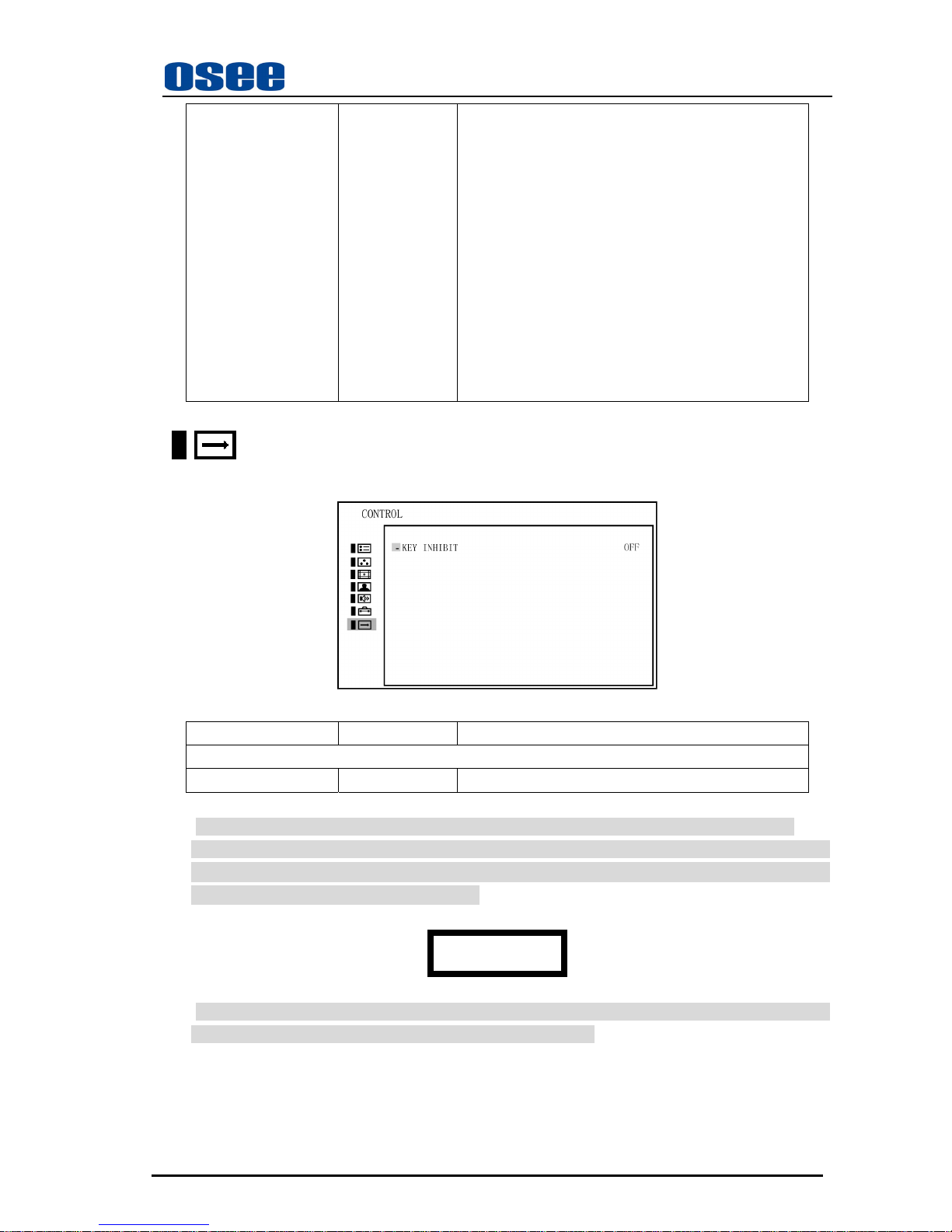
CONTROL
The CONTROL menu is used for setting the key inhibit function.
Sub Menu Settings Explanation
CONTROL
-KEY INHIBIT OFF/ON Inhibit all keys except power, menu and volume keys
If the key inhibit has been turned on, the Inhibit lamp on the front panel always lights in orange.
When you press any of the buttons except power, menu and volume, the prompt box will display on the
screen as follows, and the other button functions are not valid. (Only if the Menu button is pressed,
∧
(up),∨(down) and Enter button will be valid. )
KEY INHIBIT
The only menu setting can be changed when the key inhibit is engaged is the KEY INHIBIT ON/OFF
item. To change any of the items, turn the key inhibit to OFF first.
Page 33
LMW-171 SERIES LCD MONITOR User Manual
—29—
Chapter 7 Technical Specifications
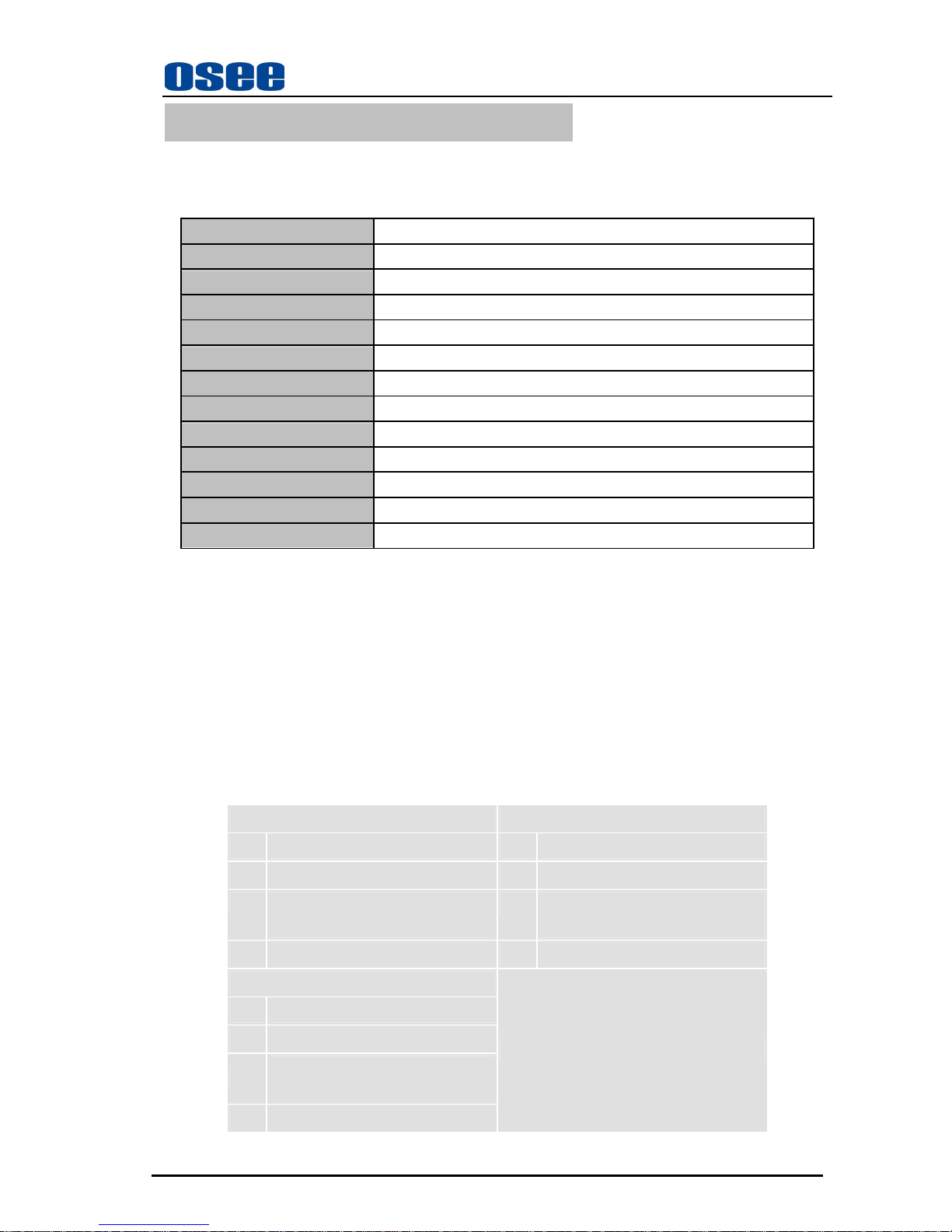
7.1 Product Detailed Information:
Display Area
17” diagonal (14.68 X 8.25”, 372.918HX 209.664V)
Viewing Angles
178 degree (H) X 178 degree (V)
Color Depth
16.7M
Resolution
1366H X 768V
Dot Pitch
0.091 H X 0.273 V
Contrast Ratio
900 :1
Response Time
Tr=8;Tf=9
Power
100~240 V A C,1.5A,60Wmax
Power Consumption
60W
Luminance, White
350 cd/m
2
Back light
White CCFL
Back light life time(Hrs) 50,000
Operating Temperature
0° C to 50° C
7.2 Inputs
¾ HD-SDI Inputs with Loop-through
¾ 1 Video Input
¾ 1 Configurable Video, Y/C, YPbPr Input
¾ 1 Configurable HDMI, VGA, DVI Input
¾ 4 Channels Audio Input
¾ GPI Inputs on RJ45
¾ RS485 with Loop-through
7.3 Component Level Definition
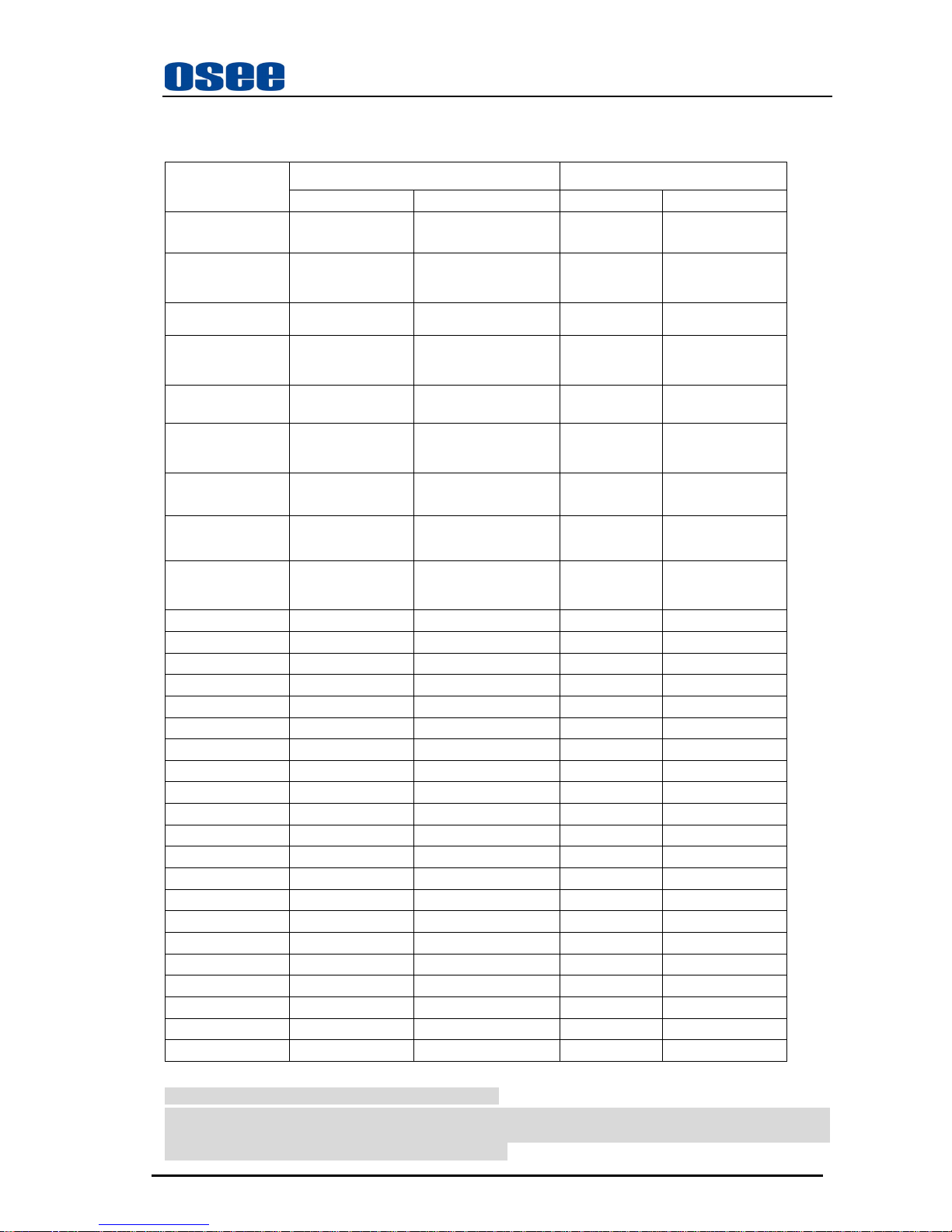
BETA 7.5 SMPTE
Setup 53.37 mV Setup 0 mV
Y 714.29 mV (Peak Luma, 100% White) Y 700.00 mV (Peak Luma, 100% White)
Pb/Pr 700.00 mVp-p (75% Color Bars)
933.34 mVp-p (100% Color Bars)
Pb/Pr 525.00 mVp-p (75% Color Bars)
700.00 mVp-p (100% Color Bars)
Sync -286 mV Sync -300 mV
BETA 0
Setup 0 mV
Y 714.30 mV (Peak Luma, 100% White)
Pb/Pr
756.80 mVp-p (75% Color Bars)
1009.0 mVp-p (100% Color Bars)
Sync -286 mV
Page 34
LMW-171 SERIES LCD MONITOR User Manual
—30—
7.4 Standard Definition Video, Frame Refresh Rate and Color Matrix (1920×1200)
Tab.1
OVERSCAN NATIVE
INPUT OUTPUT INPUT OUTPUT
NTSC 684X462
1366X768(16:9)
1024X768(4:3)
720X487 720X487
PAL 684X548
1366X768,
1024X768
720X576 720X576
SECAM 684X548
1366X768,
1024X768
720X576 720X576
NTCS-4.43 684X462
1366X768,
1024X768
720X487 720X487
PAL-M 684X462
1366X768,
1024X768
720X487 720X487
480I60 684X462
1366X768,
1024X768
720X487 720X487
576I50 684X548
1366X768,
1024X768
720X576 720X576
480P60 684X462
1366X768,
1024X768
720X487 720X487
576P50 684X548
1366X768,
1024X768
720X576 720X576
720P24 1216X684 1366X768, 1280x720 1280x720
720P25 1216X684 1366X768, 1280x720 1280x720
720P30 1216X684 1366X768, 1280x720 1280x720
720P50 1216X684 1366X768, 1280x720 1280x720
720P60 1216X684 1366X768, 1280x720 1280x720
1035I60 1824X984 1366X768, 1920X1035 1920X1035
1080I60 1824X1026 1366X768, 1920X1080 1920X1080
1080I50 1824X1026 1366X768, 1920X1080 1920X1080
1080P24 1824X1026 1366X768, 1920X1080 1920X1080
1080P25 1824X1026 1366X768, 1920X1080 1920X1080
1080P30 1824X1026 1366X768, 1920X1080 1920X1080
1080P50 1824X1026 1366X768, 1920X1080 1920X1080
1080P60 1824X1026 1366X768, 1920X1080 1920X1080
1080SF24 1824X1026 1366X768, 1920X1080 1920X1080
VGA / / / /
SVGA / / / /
XGA / / / /
SXGA / / / /
UXGA / / / /
WXGA / / / /
WUXGA / / / /
* Don’t display MARKER when SCAN is NATIVE.
* When the SCAN MODE is set to < NATIVE> and the input signal is 1080P or 1080i, repeatedly press the
SCAN button, the position of picture will display in the loop way of <center>-<TOP LEFT > - < TOP
RIGHT > - < BOT RIGHT >- < BOT LEFT >-<center>
Page 35
LMW-171 SERIES LCD MONITOR User Manual
—31—
Tab.2
FULL NORMAL
INPUT ALL OUTPUT NORMAL
Frame
Rate
Color Matrix
NTSC 720X487
1366X768(16:9)
1024X768(4:3)
60 601
PAL 720X576
1366X768,
1024X768
50 601
SECAM 720X576
1366X768,
1024X768
50 601
NTCS-4.43 720X487
1366X768,
1024X768
60 601
PAL-M 720X487
1366X768,
1024X768
60 601
480I60 720X487
1366X768,
1024X768
60 601/709
576I50 720X576
1366X768,
1024X768
50 601
480P60 720X487
1366X768,
1024X768
60 601/709
576P50 720X576
1366X768,
1024X768
50 709
720P24 1280x720 1366X768, 48 709
720P25 1280x720 1366X768, 50 709
720P30 1280x720 1366X768, 30 709
720P50 1280x720 1366X768, 50 709
720P60 1280x720 1366X768, 60 709
1035I60 1920X1035 1366X768, 60 709
1080I60 1920X1080 1366X768, 60 709
1080I50 1920X1080 1366X768, 50 709
1080P24 1920X1080 1366X768, 48 709
1080P25 1920X1080 1366X768, 50 709
1080P30 1920X1080 1366X768, 60 709
1080P50 1920X1080 1366X768, 50 709
1080P60 1920X1080 1366X768, 60 709
1080SF24 1920X1080 1366X768, 48 709
VGA 640X480 1366X768 60-75 /
SVGA 800X600 1366X768 60-75 /
XGA 1024x768 1366X768 60-75 /
SXGA 1280x1024 1366X768 60-75 /
UXGA 1600x1200 1366X768 60 /
WVGA 1366x768 1366X768 60 /
WXGA 1920x1200 1366X768 60 /
WUXGA 720X487
1366X768(16:9)
1024X768(4:3)
60 601
Page 36

LMW-171 SERIES LCD MONITOR User Manual
—32—
Chapter 8 Supplied Accessories
Standard accessories:
1. Display and Table Stand 1
2. AC Power Cord 1
3. Warranty Card 1
4. User Manual 1
Optional accesories:
Rackmount Ear:LMW171-A-RE
Battery mounter:LMW171-A-BM
Battery
Handle (not conform to standard of ROHS)
Note:Specifications are subject to change without notice.
 Loading...