

OSEE LMW-171H, LMW-171V, LMW-171S User Manual

LMW-171 SERIES LCD MONITOR
USER MANUAL
PRODUCT INFORMATION
MODEL: LMW-171 SERIES LCD MONITOR
Version: V010200
Release Date: 2010-7-30
COMPANY NAME
Beijing Osee Digital Technology Ltd.
CONTACT INFORMATION
Address: Room 702, Tower D, Jinyujiahua Building, No.9, 3rd Shangdi Street, Haidian
District, Beijing, China
Post code: 100085
Tel: 8610-62968823
Fax: 8610-62977165
Http://www.osee-dig.com
E-mail:sales@osee-dig.com

About The USER MANUAL
The user manual applies to the following device types:
z LMW-171H
z LMW-171S
z LMW-171V
The images of LMW-171H are adopted in the following descriptions. Any of the different
specifications between the device types are elaborated. Before reading the manual, please
confirm the device type.

Contents
Chapter 1 Product Overview..............................................................................................1
Chapter 2 Unpacking and Installation............................................................................... 1
Chapter 3 Dimensions.......................................................................................................... 2
Chapter 4 Operation............................................................................................................4
4.1 Status Display............................................................................................................................. 4
4.2 Input Signals................................................................................................................................5
4.3 Rear Panel Terminals.................................................................................................................6
4.4 Location and Function of Control Buttons And Knobs On Front Panel.............................10
4.5 Input Signals and Adjustable/setting Items............................................................................13
Chapter 5 Menu Operation Guide ................................................................................... 14
5.1 Selecting the Menu Language ..................................................................................................14
5.2 Using the Menu..........................................................................................................................15
Chapter 6 LMW-171 Series LCD Monitor Menu Structure......................................... 16
6.1 Main Menu.................................................................................................................................16
6.2 Adjusting and Changing the Settings......................................................................................16
Chapter 7 Technical Specifications...................................................................................29
7.1 Product Detailed Information:............................................................................................. ....29
7.2 Inputs .........................................................................................................................................29
7.3 Component Level Definition ....................................................................................................29
7.4 Standard Definition Video, Frame Refresh Rate and Color Matrix (1920×1200)...............30
Chapter 8 Supplied Accessories........................................................................................ 32

LMW-171 SERIES LCD MONITOR User Manual
—1—
Chapter 1 Product Overview
The LM171 is a cost-effective 17 inch LCD monitor that can be used for post production rooms,
broadcasters and mobile units, monitoring multi-format high definition video and audio.
The LM171 is equipped with 1366×768 high resolution panel and capable of displaying 1080 format high
definition signal at native resolution. Advanced digital video processing technology such as precise 3D
de-interlace, scaling, Gamma and color correction is used to ensure high display quality.
The LM171H can accept Video, S-video, component, SDI and HDMI format SD/HD video signal as well as
VGA or DVI PC signal.
It has various On-Screen Display feature, can display 8 channels of audio meter, time code, UMD and tally
on the LCD panel. Other features like H/V delay, NATIVE, blue/mono display, area marker and safety
marker are standard for the monitor.
Features
1366×768 Native Resolution Panel
High Quality Color Reproduction
Various Area, Safety and Center Marker
H/V Delay, NATIVE, Blue/Mono Display
8 Channel Audio Meters, Time code,UMD, Tri-color Tally
Field upgradeable
Audio De-embedding for SDI Input
Build-in Speaker and Audio Line Output
Chapter 2 Unpacking and Installation
Unpack the LMW-171 Monitor and inspect for any apparent physical damage that may have occurred in
transit. Standard and optional accessories are covered in Chapter 8 of this manual.
We recommend you retain the shipping carton for future use.
1. When installing a mount option, please assure a soft and non-scratch surfaced is used to place the
monitor on.
2. Place the monitor on the soft surface screen face down for installation of table stand or mount.
3. The following are optional accesories, if necessary, please contact the manufacturer.
y Use the included 2 pieces of GB818 M5*5 screws to attach the Rackmount Ear option on both side
of the monitor.
y Use the included 4 pieces of GB819 M3*12 screws to attach the Battery mounter option on the rear
center.
y Use the included 2 pieces of GB818 M4*13 screws to attach the handle option at the top.
4. Place the LMW-171 in the required location for operation.
5. Connect the required signals. For BNC connections use 75Ω rated connectors.
6. Connect A.C. Mains power using the included EIC power cord. Please ensure an Earth ground
present to ensure proper operation of the unit.
7. As a final step turn on the mains power using the toggle switch located on the rear of the LMW-171
above the power connection.
LMW-171 SERIES LCD MONITOR User Manual
—2—
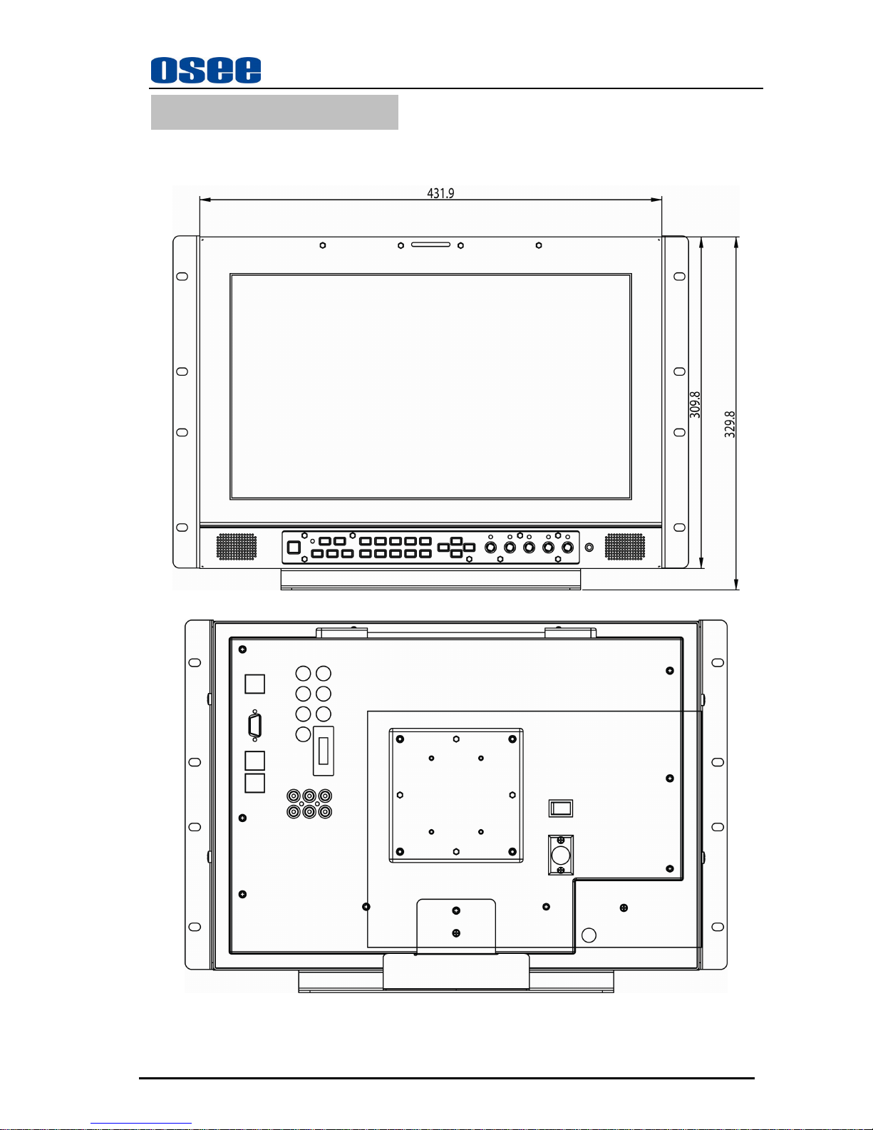
Chapter 3 Dimensions
Front View (Unit: mm)
Rear View (Unit: mm )
LMW-171 SERIES LCD MONITOR User Manual
—3—
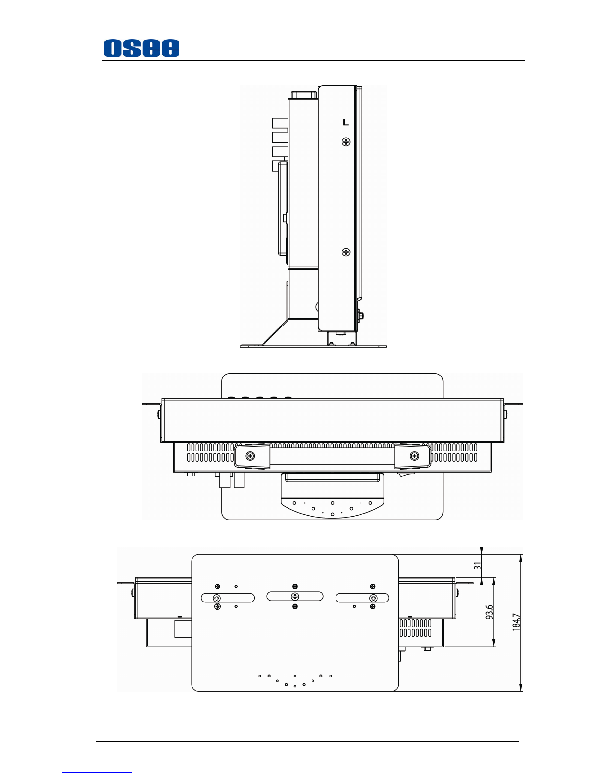
Side View (Unit: mm)
Top Side View (Unit: mm)
Bottom View
(Unit: mm)
LMW-171 SERIES LCD MONITOR User Manual
—4—
Chapter 4 Operation
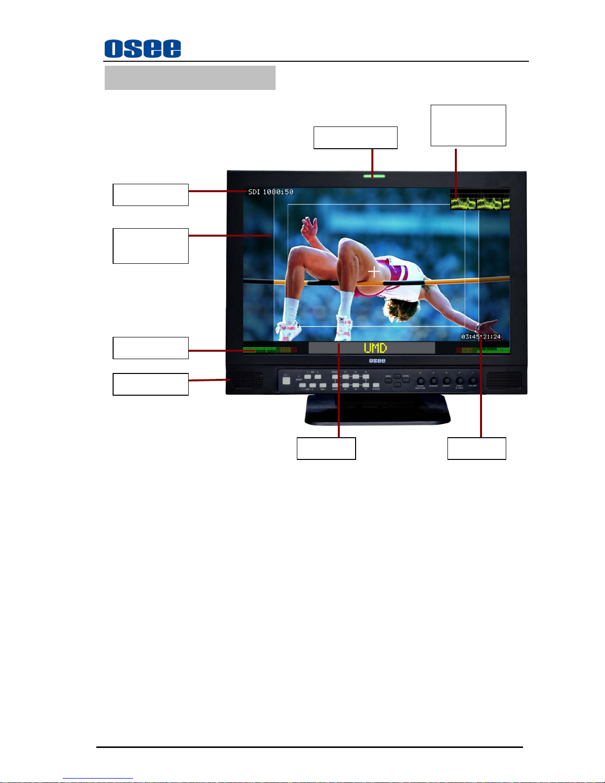
4.1 Status Display
) Tally Indicator:
It is used to check the status of the monitor by the color of the tally lamp.
(For more information, see the fourth page of “USER CONFIG” menu)
) Speakers
Output the audio which is selected by the input terminal select button.
) Wave form or vector graph
It is used to check the wave form or vector graph of the displaying signal picture.
Only used for SDI signal.
You can open and set the wave form or vector graph on the second page of “USER CONFIG” menu.
Signal format
Audio Meter
TALLY Indicator
Area & Safety
Marker
Speakers
Wave form or
vector graph
Time Code
UMD
LMW-171 SERIES LCD MONITOR User Manual
—5—
4.2 Input Signals
The following input signals are supported by the LMW-171 monitor:
Format SDI Video Y/C YPbPr HDMI DVI VGA
Device Type* LMW-171V LMW-171S LMW-171H
LMW-171 LMW-171 LMW-171 LMW-171 LMW-171 LMW-171
NTSC
/
/ /
YES YES
/
/ / /
PAL
/
/ /
YES YES
/
/ / /
SECAM
/
/ /
YES YES
/
/ / /
NTCS-4.43
/
/ /
YES YES
/
/ / /
PAL-M
/
/ /
YES YES
/
/ / /
480I60
/
YES YES
/
/
YES YES
/
/
576I50
/
YES YES
/
/
YES YES
/
/
480P60
/
/ / / /
YES YES
/
/
576P50
/
/ / / /
YES YES
/
/
720P24
/
/
YES
/
/ / / / /
720P25
/
/
YES
/
/ / / / /
720P30
/
/
YES
/
/ / / / /
720P50
/
/
YES
/
/
YES YES
/
/
720P60
/
/
YES
/
/
YES YES
/
/
1035I60
/
/
YES
/
/
YES YES
/
/
1080I60
/
/
YES
/
/
YES YES
/
/
1080I50
/
/
YES
/
/
YES YES
/
/
1080P24
/
/
YES
/
/
YES YES
/
/
1080P25
/
/
YES
/
/
YES YES
/
/
1080P30
/
/
YES
/
/
YES YES
/
/
1080P50
/
/ / / /
YES YES
/
/
1080P60
/
/ / / /
YES YES
/
/
1080SF24
/
/
YES
/
/
YES YES
/
/
VGA
/
/ / / / / /
YES YES
SVGA
/
/ / / / / /
YES YES
XGA
/
/ / / / / /
YES YES
SXGA
/
/ / / / / /
YES YES
UXGA
/
/ / / / / /
YES YES
WVGA
/
/ / / / / /
YES YES
WXGA
/
/ / / / / /
YES YES
WUXGA
/
/ / / / / /
YES YES
*: For ”Device Type”, LMW-171 includes LMW-171V, LMW-171S and LMW-171H.
“YES”: Adjustable/can be set; “\” : Not adjustable/cannot be set
LMW-171 SERIES LCD MONITOR User Manual
—6—
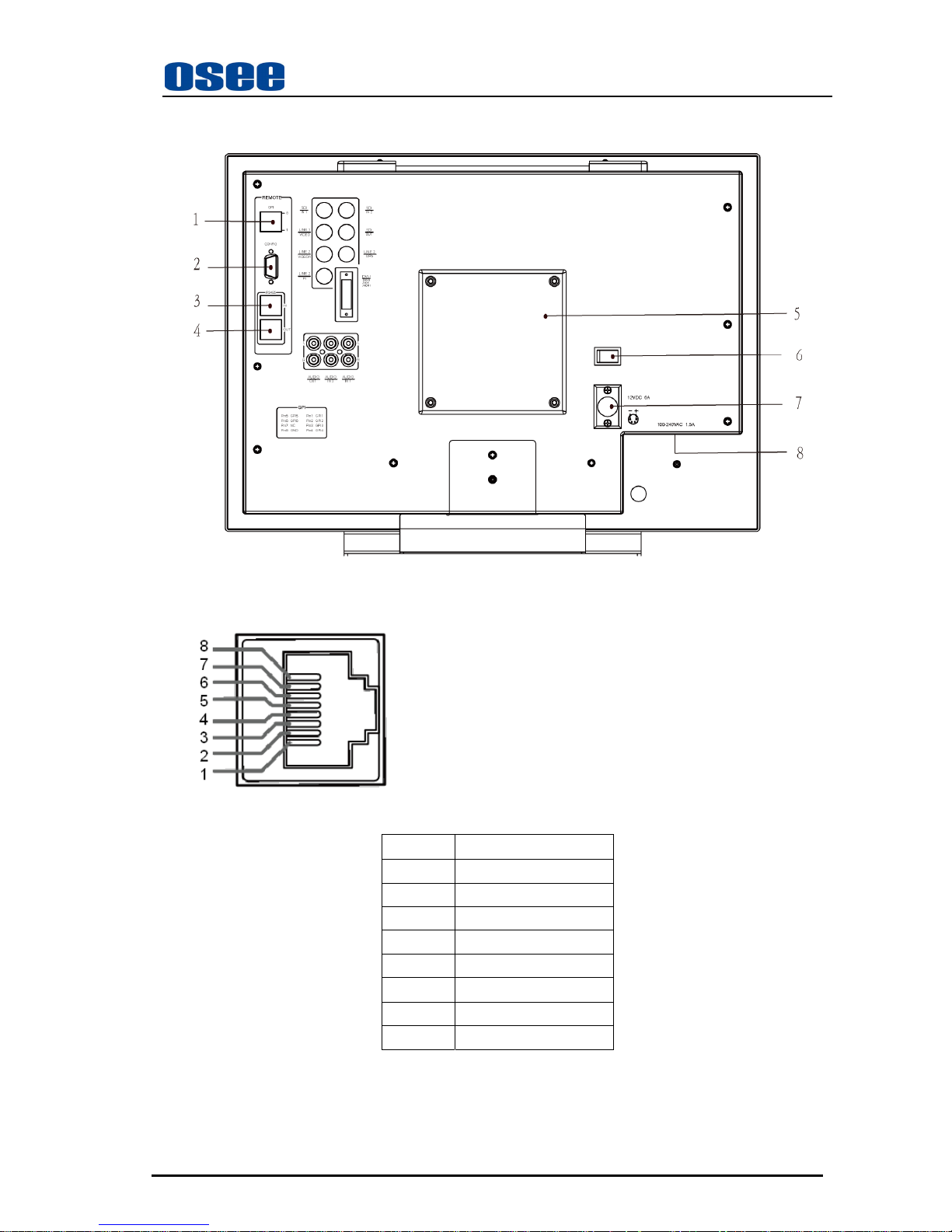
4.3 Rear Panel Terminals
A. Rear Panel
The specifications of terminals are as follows :
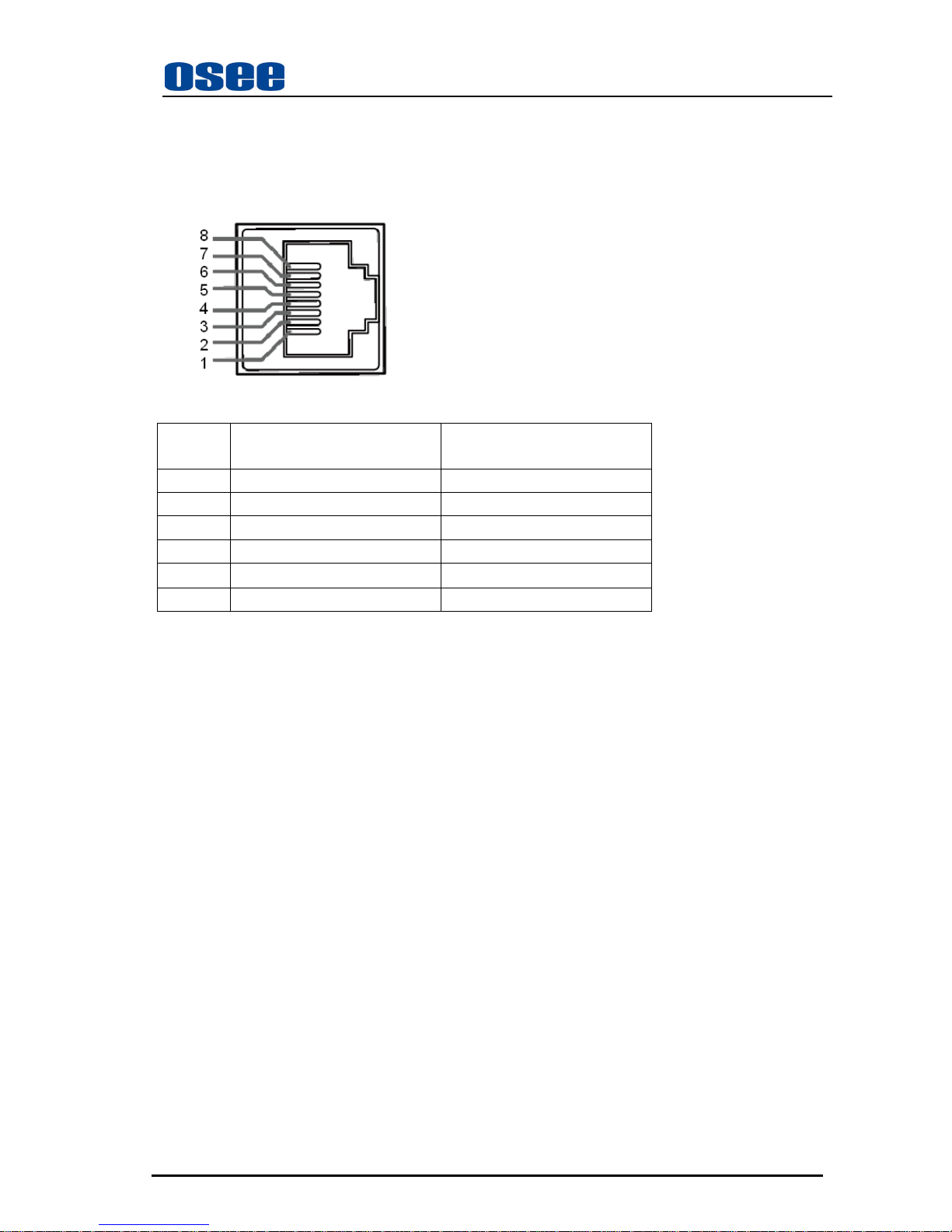
1 GPI :GPI Terminal
Female RJ-45 Receptacle
PIN Description
PIN 1 GPI1
PIN 2 GPI2
PIN 3 GPI3
PIN 4 GPI4
PIN 5 GPI5
PIN 6 GPI6
PIN 7 NC
PIN 8 GND
For the detailed information about GPI 1-GPI 6, see the fourth page of “USER CONFIG” menu.
2 CONFIG :Configuration Terminal
It is used to update the program only.
LMW-171 SERIES LCD MONITOR User Manual
—7—
3 RS485 IN : RS485 IN Terminal ;
4 RS485 OUT : RS485 OUT Terminal ;
Female RJ-45 Receptacles
Pin No. RS485 IN Terminal Signal RS485 OUT Terminal Signal
1,2 GND GND
3 Tx- Tx4 Rx+ Rx+
5 Rx- Rx6 Tx+ Tx+
7,8 NC NC
5 Battery Mounter
Install the Battery Mounter and Battery here. The Battery Mounter and Battery are
optional
accesories, if necessary, please contact the manufacturer.
6
O/– (Power) Switch
The power is turned on or off.
The monitor is turned on by pressing side–.
7 Battery Input Connector
Connect the battery here.
Total Battery consumption: 12V DC, 6A.
8 Power Input Connector
T ot al pow er consumption: 100-240V AC, 1.5A.
Equipment power consumption: 60W.
A power source with the capacity of more than 80W is recommended.
 Loading...