

OSEE LCM170-A, LCM215-A, LCM215-HDR User Manual

LCM170-A LCM215-A
LCM215-HDR
LCD Monitor
User Manual


Model:
LCM170-A/LCM215-A/LCM215-HDR LCD Monitor
Version:
V010000
Release Date:
July 10th, 2018
Address:
No.22 Building, No.68 zone, Beiqing Road, Haidian District,
Beijing, China
Post Code:
100094
Tel:
(+86) 010-62434168
Fax:
(+86) 010-62434169
Web:
http://www.osee-dig.com.cn/
E-mail:
sales@osee-dig.com
Product Information
Company
OSEE TECHNOLOGY LTD.
Contact Information

About this manual
Important
The following symbols are used in this manual:
The further information or know-how for described subjects above which
helps user to understand them better.
The safety matters or operations that user must pay attention to when
using this product.
Contents
The user manual applies to the following device types:
LCM170-A
LCM215-A
LCM215-HDR
The images of LCM170-A are adopted in the following descriptions. The basic
features and functionalities for LCM170-A, LCM215-A and LCM215-HDR are
almost as the same. Any of the different specifications between the device
types are elaborated. Before reading the manual, please confirm the device
type.

Contents
Contents .......................................................................................................... I
Chapter 1 Overview ....................................................................................... 1
Chapter 2 Safety ............................................................................................. 3
Chapter 3 Unpack and Installation ............................................................... 7
Chapter 4 Locations and Function of Parts and Control .......................... 11
4.1
Front Panel ........................................................................................ 12
4.1.1
Arrangement of Front Panel ........................................................... 12
4.1.2
Operation of Front Panel ................................................................ 14
4.2
Rear Panel ......................................................................................... 17
4.2.1
Arrangement of Rear Panel ............................................................ 17
4.2.2
Operations of Rear Panel ............................................................... 18
4.3
Supported Signal Format ................................................................. 20
Chapter 5 Menu Operations ................................ ................................ ........ 23
5.1
Main Menu.......................................................................................... 23
5.1.1
STATUS Menu ............................................................................... 25
5.1.2
INPUT CONFIG Menu .................................................................... 26
5.1.3
COLOR MANAGEMENT Menu ...................................................... 27
5.1.4
USER CONFIG Menu ..................................................................... 32
5.1.5
IMD CONFIG Menu ........................................................................ 52
5.1.6
KEY INHIBIT Menu ......................................................................... 53
5.2
Menu Settings .................................................................................... 54
Chapter 6 Specifications ............................................................................. 57
I

Overview
Chapter 1 Overview
The LCM170-A LCD Monitor are high performance broadcast monitor tailoring
most applications from program production, intensive upload/download,
playout to studio and intensive monitoring all sorts of business in TV Stations.
The front frame of the unit comes in a slim bezel design made from rubber
mold. The professional TFT glass at full resolution of 1920x1080 UHD with
LED backlight makes the LCM170-A LCD monitor capable of reproducing a
natural color at quickest response time. In addition, the unit boasts a full wide
viewing angle as well as excellent brightness and contrast ratio.
By adopting the advanced 10-bit digital signal processing technology plus 3D
comb filter, de-interlacing capability and accurate scaling ensures the
LCM170-A LCD Monitor to achieve a better effect of smoother and more
natural image.
The LCM170-A LCD Monitor supports up to 2Ch 3G/HD/SD-SDI inputs, 1Ch
VIDEO input, one HDMI input and 1Ch 3G/HD/SD-SDI output.
The LCM170-A LCD Monitor delivers much capable display functionality like
waveform, vector scope, histogram, zebra, audio meter, focus assist, exposure
assist, TC, IMD and all kinds of markers.
Figure 1 A Diagram of LCM170-A Monitor
1

Overview
Features
Prevailing slim bezel design
Having multi format input including 3G/HD/SD-SDI, VIDEO and HDMI
Adopting full HD, wide viewing angle TFT glass
Using 10-bit signal processing technology plus advanced conversion
technology between the interlacing and the progressive
Support waveform, vector scope, histogram and audio meter
Support HDR technology and wide range color space
Support multiple color space: SMPTE-C, EBU, ITU709, ITU2020, P3
Support multiple assistants: zebra, focus assist, exposure assist
Support IMD remote control
Functionality
Support MARKER, Time Code, MET display
Support presetting the color temperature using customized values
2

Safety
Chapter 2 Safety
FCC Caution:
Any Changes or modifications not expressly approved by the party responsible
for compliance could void the user's authority to operate the equipment.
This device complies with part 15 of the FCC Rules.
Operation is subject to the following two conditions: (1) This device may not
cause harmful interference, and (2) this device must accept any interference
received, including interference that may cause undesired operation.
Note: This equipment has been tested and found to comply with the limits for a
Class B digital device, pursuant to part 15 of the FCC Rules. These limits are
designed to provide reasonable protection against harmful interference in a
residential installation. This equipment generates uses and can radiate radio
frequency energy and, if not installed and used in accordance with the
instructions, may cause harmful interference to radio communications.
However, there is no guarantee that interference will not occur in a particular
installation. If this equipment does cause harmful interference to radio or
television reception, which can be determined by turning the equipment off and
on, the user is encouraged to try to correct the interference by one or more of
the following measures:
Reorient or relocate the receiving antenna.
Increase the separation between the equipment and receiver.
Connect the equipment into an outlet on a circuit different from that to which
the receiver is connected.
Consult the dealer or an experienced radio/TV technician for help.
3

Safety
Warnings:
Read, keep and follow all of these instructions for your safety. Heed all
warnings.
Device
Install in accordance with the manufacturer's instructions.
Do not beat with a hard object or scratch the LCD display.
Do not make the freeze picture displaying on the screen time too long,
otherwise, it will leave the afterimage on the screen.
If the brightness is adjusted to the minimum, then it might be hard to
see the display screen.
Refer all servicing to qualified service personnel. Servicing will be
required under all of the following conditions:
The unit has been exposed to rain or moisture.
Liquid had been spilled or objects have fallen onto the unit.
The unit has been damaged in any way, such as when the
power-supply cord or plug is damaged.
The unit does not operate normally.
Clean only with dry cloth.
Specifications are subject to change without notice.
Position
Do not block any ventilation openings.
Do not use this unit near water.
Do not expose the unit to rain or moisture.
Do not use this unit near any heat sources such as radiators, heat
registers, stoves, or other apparatus (including amplifiers) that product
4
Safety
heat.
A nameplate indicating operating voltage, etc., is located on the rear
panel.
The socket-outlet shall be installed near the equipment and shall be
easily accessible.
Power Supply Cord
Do not defeat the safety purpose of the polarized or grounding-type
plug.
Do not damage the power cord, place the heavy objects on the power
cord, stretch the power cord, or bend the power cord.
Protect the power cord from being walked on or pinched, particularly at
plugs, convenience receptacles, and the point where they exit from the
unit.
If the power cord is damaged, turn off the power immediately. It is
dangerous to use the unit with a damaged power cord. It may cause
fire or electric shock.
Unplug this unit during lighting storms or when unused for long periods
of time.
Disconnect the power cord from the AC outlet by grasping the plug, not
by pulling the cord.
Should any solid object or liquid fall into the cabinet, unplug the unit
and have it checked by qualified personnel before operating it any
further.
5

6
Unpack and Installation
No.
Item
Quantity
1
1
2
2
3
Power cord
1
4
1
5
1
6
1
Chapter 3 Unpack and Installation
Unpack:
When unpacking the components of LCM170-A monitor, please verify that
none of the components listed in Table 3.1 are damaged or lack. If there is any
missing, contact your distributors or OSEE Technology Ltd. for it.
Table 3-1 Packing List
Device
Stands with screws
User manual
warranty card
Certificate card
Installation:
1. Prepare for installation
Please follow the procedures below before installing LCM170-A:
Check the equipment for any invisible damage that may have occurred
during transit.
Confirm all the items listed on the packing list have been received.
Remove all the packing material including electrostatic-resistant
packing.
Retain these packing materials for future use.
2. Mount a LCM170-A in your desired location. Adequate ventilation is
required when installed to prevent possible damage to the
LCM170-A.
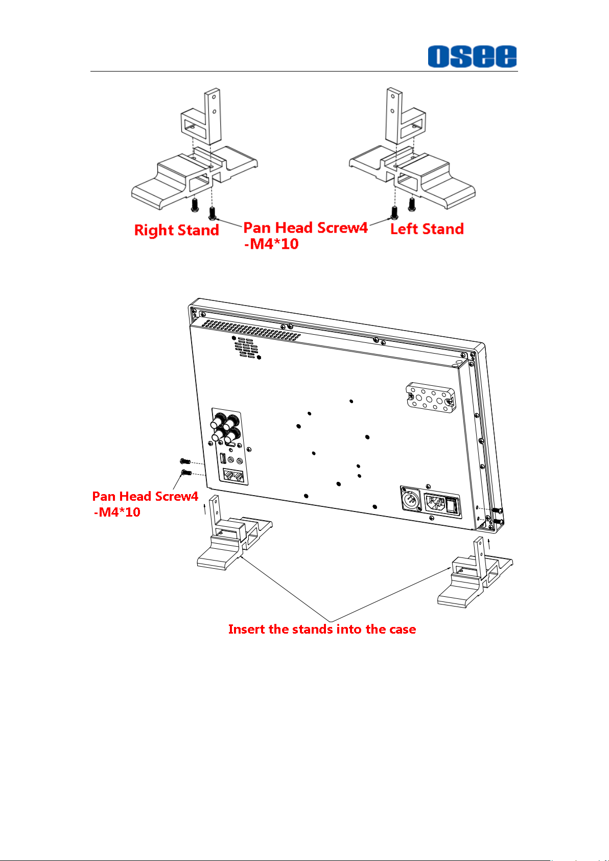
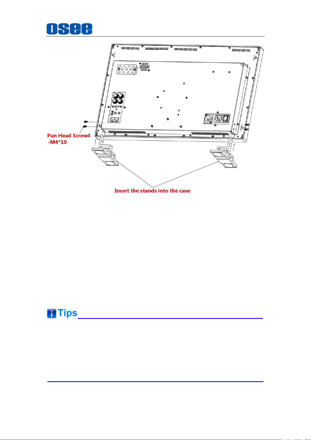
There are screw holes at the rear panel of the monitor, which are
labeled in the following figures. Assemble the parts of the stands, then
insert the stands into the case, and fasten it with the screws provided.
The stands installation for LCM170-A and LCM215-A(LCM215-HDR)
are as follows:
7
Unpack and Installation
Figure 3-1 Stands Assembly
Figure 3-2 Stands for LCM170-A
8
Unpack and Installation
Figure 3-3 Stands for LCM215-A/LCM215-HDR
3. Connect required cables for signal input and output. For BNC
connections use 75Ω rated connectors.
4. Connect 100~240V50/60Hz AC or 11~17V3A DC power source
using the power cord, or 11~16.8V DC camera battery(with
optional battery plate).
5. Connect the power cord to the power interface.
6. Fasten the power protect accessory.
7. As a final step, turn on the device by pressing the corresponding
power switch located on the front panel.
The pedestal and the monitor are packaged separately.
Connect a standard signal line to the corresponding input port. All BNC
connector impedance must be 75Ω.
Please use the power cord supplied to avoid unnecessary trouble.
9

10
Locations and Function of Parts and Control
Chapter 4 Locations and Function of Parts and
Control
This chapter describes the features of LCM170-A monitor. The features of
LCM170-A monitor are as shown in Figure 4-1 after installed and powered
on:
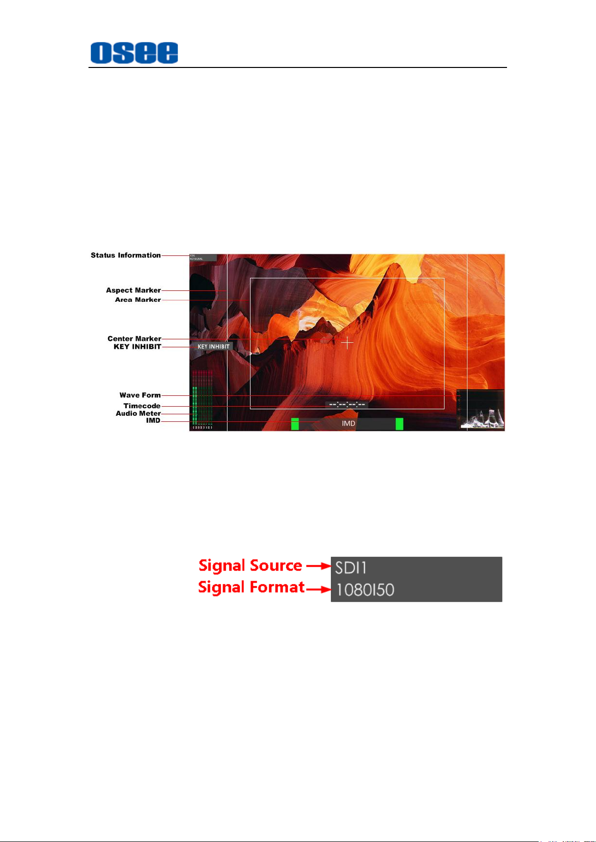
Figure 4-1 Features of LCM170-A Monitor
1. Status Information
The Status Information is displayed in the top left corner of the
screen, and includes the input channel and signal format. You can
define it in USER CONFIG menu.
2. Waveform and Vector
This is effective only for SDI signal. The waveform and vector of the
input signal are configurable in the MAIN Menu.
3. Aspect Marker
It is used to mark different area of the image. You can set whether to
display it or not and their displaying mode in USER CONFIG menu.
4. Area Marker
It is used to mark different area of the image. You can set whether to
11

Locations and Function of Parts and Control
display it or not and their displaying mode in USER CONFIG menu
5. Center Marker
It is displayed in the center of the screen, and marks the center of the
image. You can set whether to display it or not in USER CONFIG
menu.
6. Audio Meter
It is displayed for audio monitoring. You can set its groups, position
and mode in USER CONFIG menu.
7. Timecode
It is displayed at the bottom of the image, the format is HH:MM:SS:FF,
if there is no timecode available, the monitor will display --:--:--:--.
8. IMD
The IMD text displays at the bottom of the screen, the length can’t
exceed 16 characters, and you can choose letter, number or other
character for it.
The
Status Information
usually displays as the following situations:
"UNKNOW” appears if an unsupported signal is input.
“NO SIGNAL” appears if no signal is input.
The signal is normal, for example: 1080i59.94, 720P50, etc.
4.1 Front Panel
It will introduce the arrangement and the operations of the buttons in front of
the panel in the following.
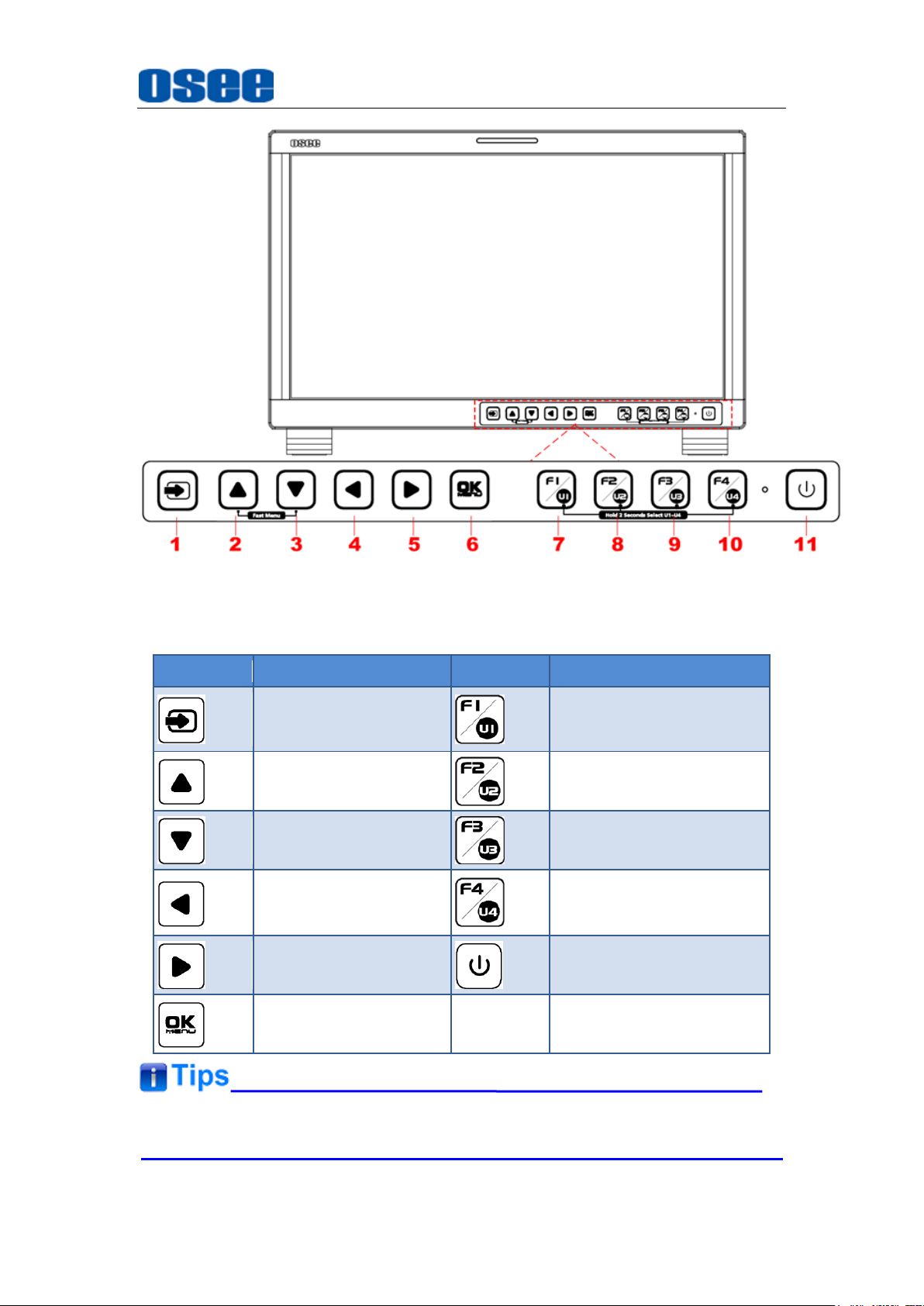
4.1.1 Arrangement of Front Panel
There are a series of buttons at the bottom of the screen, and these
buttons are used to control the screen menu items.
12
Locations and Function of Parts and Control
BUTTON
FUNCTION
BUTTON
FUNCTION
Input selection
Function button F1
Adjust upward
Function button F2
Adjust downward
Function button F3
Return/Exit
Function button F4
Select next
Power on/off
Save/Return/Main
menu
Figure 4.1-1 the Buttons in Front Panel
As shown in Figure 4.1-1, the buttons of LCM170-A are as follows:
All of these buttons have light indicators.
13
Locations and Function of Parts and Control
4.1.2 Operation of Front Panel
The functionality and usage of the buttons at the front panel are as
follows:
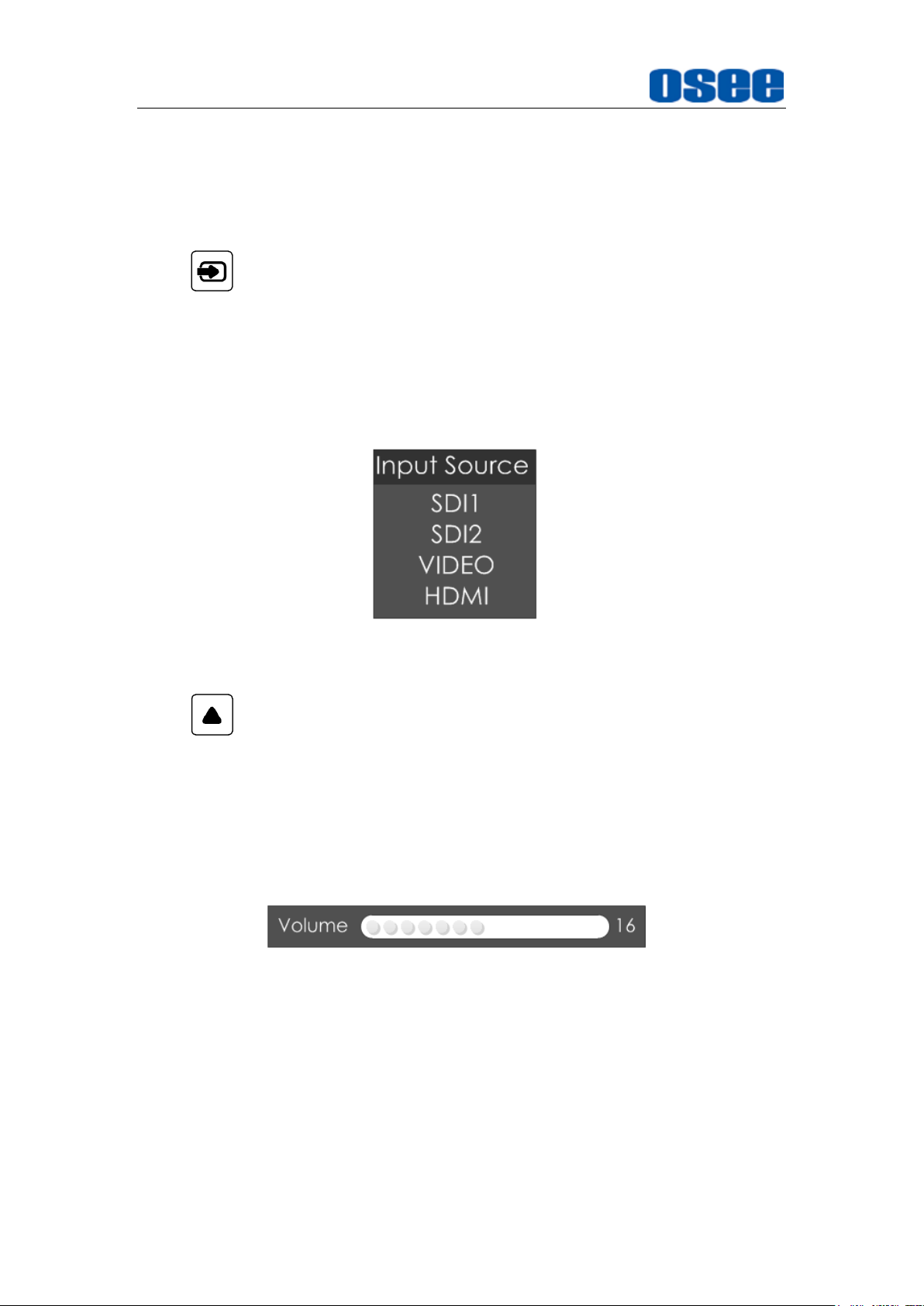
1. : Input Selection
Select the input signal from each input interface. Press this button to
display the input source menu at the top right corner of the screen, as
shown in Figure 4.1-2. Use it to select an input signal source, press it
again to toggle among these input signal items, or after the input source
menu displayed, use the UP or DOWN button to toggle among these
input signal items.
Figure 4.1-2 Source Menu
2. : UP ARROW
It is UP button when working with the main menu. Toggle this button
to select the next item or increase the number.
Without the Main menu: when not displaying the Main menu, press
LEFT
button to display the
Fast Menu
toggle among these menu items:
Saturation, Backlight
and
Sharpness
list, as shown in Figure 4.1-3,
Volume, Brightness, Contrast
.
Figure 4.1-3 Fast Menu List
After displaying the
Fast Menu
, press
LEFT
or
RIGHT
arrow button to
adjust the menu value.
The limitations of these items are shown in Table 4.1-1:
,
Table 4.1-1 The Description of Fast Menu Items
14
Locations and Function of Parts and Control
Adjust Menu
Description
Range
Default
Volume
Adjust the volume
0~31
16
Brightness
Adjust the image brightness
0~100
50
Contrast
Adjust the image contrast
0~100
50
Saturation
Adjust the image color intensity
0~100
50
Backlight
Adjust the backlight
0~10
5
Sharpness
Adjust the image sharpness
0~63
8
After you have loaded the adjust menu list, it will be closed automatically if
you do nothing operation on it within the
Osd Time
.
The main menu, the fast menu, the function menu and the input signal
selection list of a screen may not be shown all simultaneously.
3. : DOWN ARROW
It is
DOWN
button when working with the main menu. Toggle this
button to select the next item or decrease the number.
Without the Main menu: when not displaying the Main menu, press
DOWN
button to display the
Fast Menu
list, refer to the details in the
above description as in UP arrow button.
4. : LEFT ARROW
Press this button to do the following operations:
With the Main menu: when working with the Main menu, LEFT button
achieve the following functions:
Back to the higher level menu
Back to the higher level menu and not save the setting of the menu
item value
Quit the Main menu
With the Fast menu: when displaying the Fast menu, press
button to decrease the item value.
LEFT
15
 Loading...