

Page 1

1
LCM156-E/LCM170-E/
LCM230-E Series
LCD Monitor
User Manual
Page 2

Page 3

3
Product Information
Model:
LCM156-E/LCM170-E/ LCM230-E Series LCD Monitor
Version:
V010002
Release Date:
February 14th, 2017
Company
OSEE TECHNOLOGY CO., LTD.
Contact Information
OSEE TECHNOLOGY CO., LTD.
Address:
No.22 Building, No.68 zone, Beiqing Road, Haidian District,
Beijing, China
Post Code:
100094
Tel:
(+86) 010-62434168
Fax:
(+86) 010-62434169
Web:
http://www.osee-dig.com/
E-mail:
OSEE AMERICAS, LTD.
Address:
43218 Christy Street, Fremont, CA
Post Code:
94538
Tel:
(+1)510-966-4499
Web:
www.oseedirect.com / www.oseeamericas.com
E-mail:
Page 4
4
About this manual
Important
The following symbols are used in this manual:
The further information or know-how for described subjects above which
helps user to understand them better.
The safety matters or operations that user must pay attention to when
using this product.
Contents
The user manual applies to the following device types:
LCM156-E
LCM170-E
LCM230-E
The images and descriptions of LCM156-E are adopted as examples in the
following document. The basic features and functionalities for LCM156-E,
LCM170-E and LCM230-E are almost as the same, any of the different
specifications among the device types are elaborated.
Before reading the manual, please confirm the device type.
Page 5

I
Contents
Contents .......................................................................................................... I
Chapter 1 Safety ............................................................................................. 1
Chapter 2 Unpack and Installation ............................................................... 5
Chapter 3 Locations and Function of Parts and Control ............................ 9
3.1
Front Panel .......................................................................................... 9
3.1.1
Location of Control Buttons .............................................................. 9
3.1.2
Function of Control Buttons .............................................................. 9
3.2
Rear Panel ......................................................................................... 13
3.3
Supported Signal Format ................................................................. 18
Chapter 4 Menu Operations ........................................................................ 21
4.1
Main Menu.......................................................................................... 22
4.1.1
STATUS Menu ............................................................................... 24
4.1.2
INPUT SELECT Menu .................................................................... 25
4.1.3
MARKER Menu .............................................................................. 28
4.1.4
AUDIO Menu .................................................................................. 32
4.1.5
DISPLAY Menu .............................................................................. 36
4.1.6
CLOSED CAPTION Menu .............................................................. 40
4.1.7
CONFIG Menu ................................................................................ 42
4.1.8
LOOK PROFILE Menu ................................................................... 49
4.1.9
FUNCTION KEY Menu ................................................................... 51
4.1.10
KEY INHIBIT Menu ....................................................................... 56
4.2
Menu Settings .................................................................................... 58
Chapter 5 Specifications ............................................................................. 61
5.1
Product detailed information ........................................................... 61
5.2
Optional Accessories ........................................................................ 62
5.3
Dimensions ........................................................................................ 71
Page 6

Page 7

Safety
1
Chapter 1 Safety
FCC Caution:
Any Changes or modifications not expressly approved by the party responsible for
compliance could void the user's authority to operate the equipment.
This device complies with part 15 of the FCC Rules.
Operation is subject to the following two conditions: (1) This device may not cause
harmful interference, and (2) this device must accept any interference received,
including interference that may cause undesired operation.
Note: This equipment has been tested and found to comply with the limits for a Class
B digital device, pursuant to part 15 of the FCC Rules. These limits are designed to
provide reasonable protection against harmful interference in a residential installation.
This equipment generates uses and can radiate radio frequency energy and, if not
installed and used in accordance with the instructions, may cause harmful
interference to radio communications. However, there is no guarantee that
interference will not occur in a particular installation. If this equipment does cause
harmful interference to radio or television reception, which can be determined by
turning the equipment off and on, the user is encouraged to try to correct the
interference by one or more of the following measures:
Reorient or relocate the receiving antenna.
Increase the separation between the equipment and receiver.
Connect the equipment into an outlet on a circuit different from that to which the
receiver is connected.
Consult the dealer or an experienced radio/TV technician for help.
Page 8

Safety
2
Warnings:
Read, keep and follow all of these instructions for your safety. Heed all warnings.
Device
Install in accordance with the manufacturer's instructions.
Do not beat with a hard object or scratch the LCD display.
Do not make the freeze picture displaying on the screen time too long,
otherwise, it will leave the afterimage on the screen.
If the brightness is adjusted to the minimum, then it might be hard to see the
display screen.
Refer all servicing to qualified service personnel. Servicing is required if any of
the following occurs:
The unit has been exposed to rain or moisture.
Liquid had been spilled or objects have fallen onto the unit.
The unit has been damaged in any way, such as when the power-supply
cord or plug is damaged.
The unit does not operate normally, or has been dropped.
Clean only with dry cloth.
Do not block any ventilation openings. Leave enough space around the unit
for ventilation.
Do not use this unit near water.
Do not use this unit near any heat sources such as radiators, heat registers,
stoves, or other apparatus (including amplifiers) that product heat.
A nameplate indicating operating voltage, etc., is located on the rear panel.
The socket-outlet shall be installed near the equipment and shall be easily
accessible.
To reduce the risk of fire or electric shock, do not expose the unit to rain or
moisture.
To avoid electrical shock, do not open the cabinet. Refer all servicing to
qualified service personnel.
If the product needs replacement parts, make sure that the service person use
replacement parts specified by the manufacture, or those with the same
characteristics and performance as the original parts. Use of unauthorized
parts can result in fire, electric shock and/or other damage.
The panel used in this produce is made of glass. Therefore, it can break when
it is dropped or applied with impact. Be careful not to be injured by broken
glass pieces.
Page 9
3
Specifications are subject to change without notice.
Do not use attachments or accessories not recommended by the manufacture.
Use of inadequate attachments may result in serious accidents.
Do not overload AC outlet or extension cord. Overloading can cause fire or
serious electric shock.
Do not defeat the safety purpose of the polarized or grounding-type plug.
Do not damage the power cord, place the heavy objects on the power cord,
stretch the power cord, or bend the power cord.
Protect the power cord from being walked on or pinched, particularly at plugs,
convenience receptacles, and the point where they exit from the unit.
If the power cord is damaged, turn off the power immediately. It is dangerous
to use the unit with a damaged power cord. It may cause fire or electric shock.
Unplug this unit during lighting storms or when unused for long periods of
time.
Disconnect the power cord from the AC outlet by grasping the plug, not by
pulling the cord.
Should any solid object or liquid fall into the cabinet, unplug the unit and have
it checked by qualified personnel before operating it any further.
Page 10

4
Page 11
Unpack and Installation
5
Chapter 2 Unpack and Installation
Unpack:
When unpacking the LCM156-E monitor, please verify that none of the components
listed in Table 3.1 are damaged or missing. If there are any components missing,
please contact your distributors or OSEE for it.
Table 3-1 Packing List
No.
Item
Quantity
1
Device
1
2
Pedestal with screws
1
3
Power cord
1
4
Adapter
1
5
User manual
1
Installation:
1. Prepare for installation
Please follow the procedures below before installing LCM156-E:
Check the package and equipment for any visible damage that may have
occurred during transit.
Confirm all the items listed on the packing list have been received.
Remove all the packing material including electrostatic-resistant packing.
Retain these packing materials for future use.
2. Install the LCM156-E in your desired method. Adequate ventilation is
required when installed to prevent possible damage to the LCM156-E.
(Note operational specifications are 400 C (1000 F)).
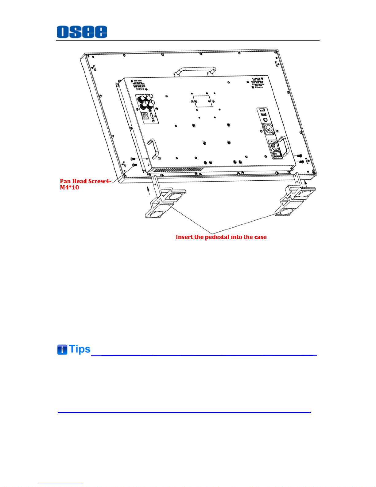
There are screw holes at the rear panel of LCM-E series monitors, which are
labeled in the following figures. Insert the pedestal into the case, and fasten it with
the screws provided. The pedestal of LCM-156E(Optional), LCM-170E and
LCM-230E are not quite the same. Assemble the pedestal as follows:
Page 12

Unpack and Installation
6
Figure 2-1 Assemble Pedestal of LCM-156E
Figure 2-2 Assemble Pedestal of LCM-170E
Page 13
Unpack and Installation
7
Figure 2-3 Assemble Pedestal of LCM-230E
3. Connect required cables for signal input and output. For BNC
connections use 75Ω rated connectors.
4. Connect the 12V5A DC power source using the included power supply or
optional battery adapter and D-Tap to Power cable when not using Land
Line power.
5. As a final step, turn on the device by toggling the power switch located on
the rear of the unit near the power jack.
Connect a standard signal line to the corresponding input port.
Please use the power adapter supplied for AC power.
The factory default value for IP address is 192.168.1.86.
Page 14

8
Page 15
Locations and Function of Parts and Control
9
Chapter 3 Locations and Function of
Parts and Control
3.1 Front Panel
3.1.1 Location of Control Buttons
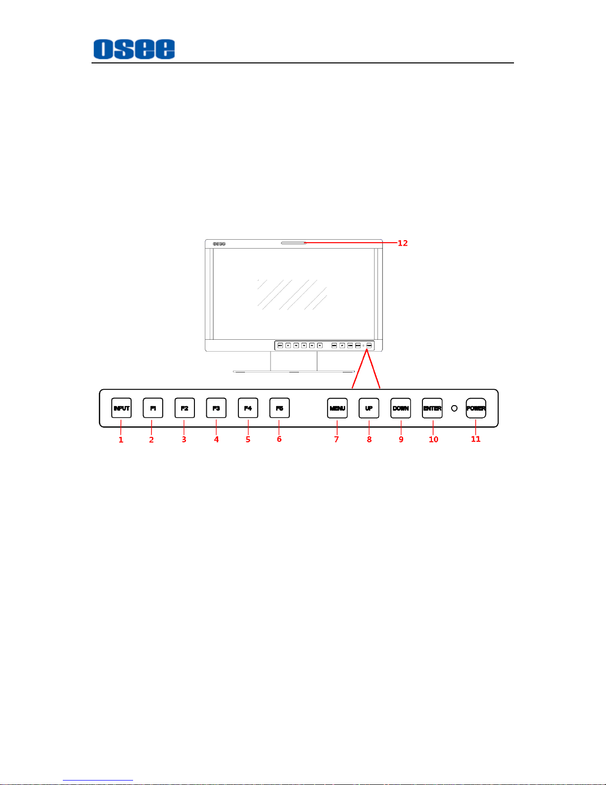
The control buttons are at the bottom of the screen, as shown in Figure 3.1-1.
Figure 3.1-1 Buttons in Front Panel
1. INPUT: Input selection button
2. F1: Function button
3. F2: Function button
4. F3: Function button
5. F4: Function button
6. F5: Function button
7. MENU: Menu operation button
8. UP: Menu operation button
9. DOWN: Menu operation button
10. ENTER: Menu operation
button
11. POWER/Lamp
12. TALLY: TALLY indicator(LED
TALLY)
3.1.2 Function of Control Buttons
INPUT Selection Button
Press INPUT button and toggle or use the UP/DOWN button to select and display
the corresponding signal input to each connector.
Page 16
Locations and Function of Parts and Control
10
SDI1
: monitor the
SDI
input as the active signal through the
SDI1 IN
connector.
SDI2
: monitor the
SDI
input as the active signal through the
SDI2 IN
connector.
LINE1(CVBS)
: monitor the
Composite Analog Input
as the active signal
through the
LINE1 IN
connector.
LINE2(CVBS)
: monitor the
Composite Analog Input
as the active signal
through the
LINE2 IN
connector.
LINE2(Y/C)
: monitor the
Composite Analog Input
as the active signal
through the
Y IN
connector and C IN connector.
LINE2(YPBPR)
: monitor the
Composite Analog Input
as the active signal
through the Y IN connector,
Pb IN
connector and
Pr IN
connector.
HDMI
: monitor the
HDMI
or
DVI
input as the active signal through the
HDMI
IN
connector.
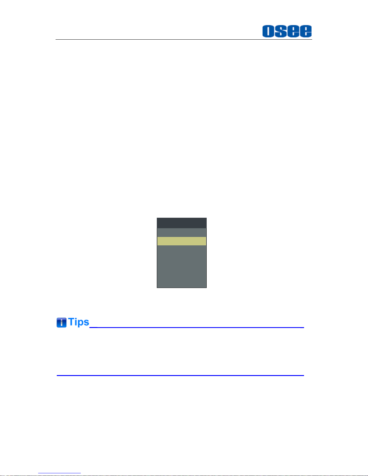
When switching an input source, it will display the SOURCE menu at the right top
corner of the screen, and the current active source is labeled in highlight yellow, as
shown in Figure 3.1-2.
SDI1
LINE1(CVBS)
LINE2(CVBS)
LINE2(Y/C)
SOURCE
SDI2
LINE2(YPBPR)
HDMI
Figure 3.1-2 Source Menu
Particularly, in PIP/PBP display mode, the signal source for the main picture is
set by INPUT button, while the slave picture’s is set through the CONFIGSUB
IN SELECT item in main menu, refer to “4.1.7 CONFIG Menu” for the details.
Function Buttons
F1~F5 button are all function buttons. Pressing any F button will display the
assigned Functions. Pressing the desired function will select the function. When
selected, the Function will then toggle through the desired setting including OFF.
The function of each button can be set via the FUNCTION KEY setting in the main
Page 17
Locations and Function of Parts and Control
11
menu.
OPERATION: for example
, press F1 to display the
FUNCTION
menu at the left
bottom corner of the screen, as shown in Figure 3.1-3. Toggle F1 button to
change the value related to this function without the setting value display.
F1 ONFLASE COLOR
F2 OFFNATIVE
FUNCTION
F3 OFFMONO
F4 OFFFREEZE
F5 OFFPBP
Figure 3.1-3 Function Menu
The
FUNCTION
menu will be closed automatically ten seconds after the last
button push.
You can assign various functions to each F1~F5 button through
FUNCTION
KEY
menu. Refer to "4.1.9 FUNCTION KEY Menu" for the details.
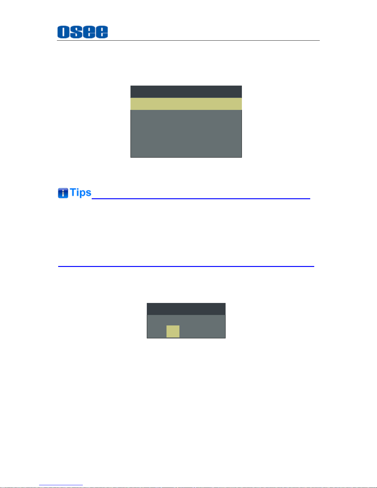
FACTORY RESET Function.
Press and hold the INPUT+F2 button for 3 seconds to access the menu in Figure
3.1-4.
Factory Reset Now?
No
Yes
FACTORY RESET
Figure 3.1-4 Reset Menu
Menu Operation Buttons
Display or set the MAIN menu.
MENU Button
Used to activate MAIN menu.
Press to display the MAIN menu
Press again to clear the MAIN menu
Page 18

Locations and Function of Parts and Control
12
UP
Used to navigate on-screen menu.
Toggle this button to select the previous item or increase the item value.
DOWN
Used to navigate on-screen menu.
Toggle this button to select the next item or decrease the item value.
ENTER
Used to navigate on-screen menu, confirm selection with the MAIN menu, or
load the Adjust menu.
MENU Selection and Setting
When displaying the MAIN menu, press
ENTER
button to select a menu item or
setting value, the active item is labeled in a highlight color, then press
ENTER
button to confirm the settings, otherwise, press
MENU
button to give up the
modification and turn back the higher level menu item.
Refer to “4.2 Menu Settings” for detail about the MAIN Menu operations.
Adjust Menu-Adjust VOLUME, BRIGHTNESS, CONTRAST, CHROMA
When not displaying the MAIN menu, press
ENTER
button to display the
Adjust
menu, as shown in Figure 3.1-5.
Toggle among these adjustable items: VOLUME, BRIGHTNESS, CONTRAST,
CHROMA.
BRIGHTNESS 50
Figure 3.1-5 Adjust Menu
After displaying the Adjust menu, press UP or
DOWN
button to adjust the item
value, and then press
ENTER
button to confirm the value setting. The
relationship of the items and their range is list in Table 3.1-1:
Table 3.1-1 The Description of Adjust Menu Items
Adjust Menu
Description
Range
Default
VOLUME
Adjust the volume
0~31dB
16
BRIGHTNESS
Adjust the image brightness
0~100
50
CONTRAST
Adjust the image contrast
0~100
50
CHROMA
Adjust the image monochroma
0~100
50
The
Adjust
menu will be closed automatically ten seconds after the last button
Page 19
Locations and Function of Parts and Control
13
push.
Power Button and Indicator
Used to turn the power to place the monitor into standby mode/off.
When the device is off(Red), press the
POWER
button to turn it on. The power
indicator lights in green.
Flashing green indicates no signal is present (refer to section 3.1.1)
When the device is on, press the
POWER
button to turn it off. The power
indicator lights in red.
3.2 Rear Panel
For the arrangement of the rear panel of LCM170-E and LCM230-E are the same,
which are different from the LCM156-E’s.
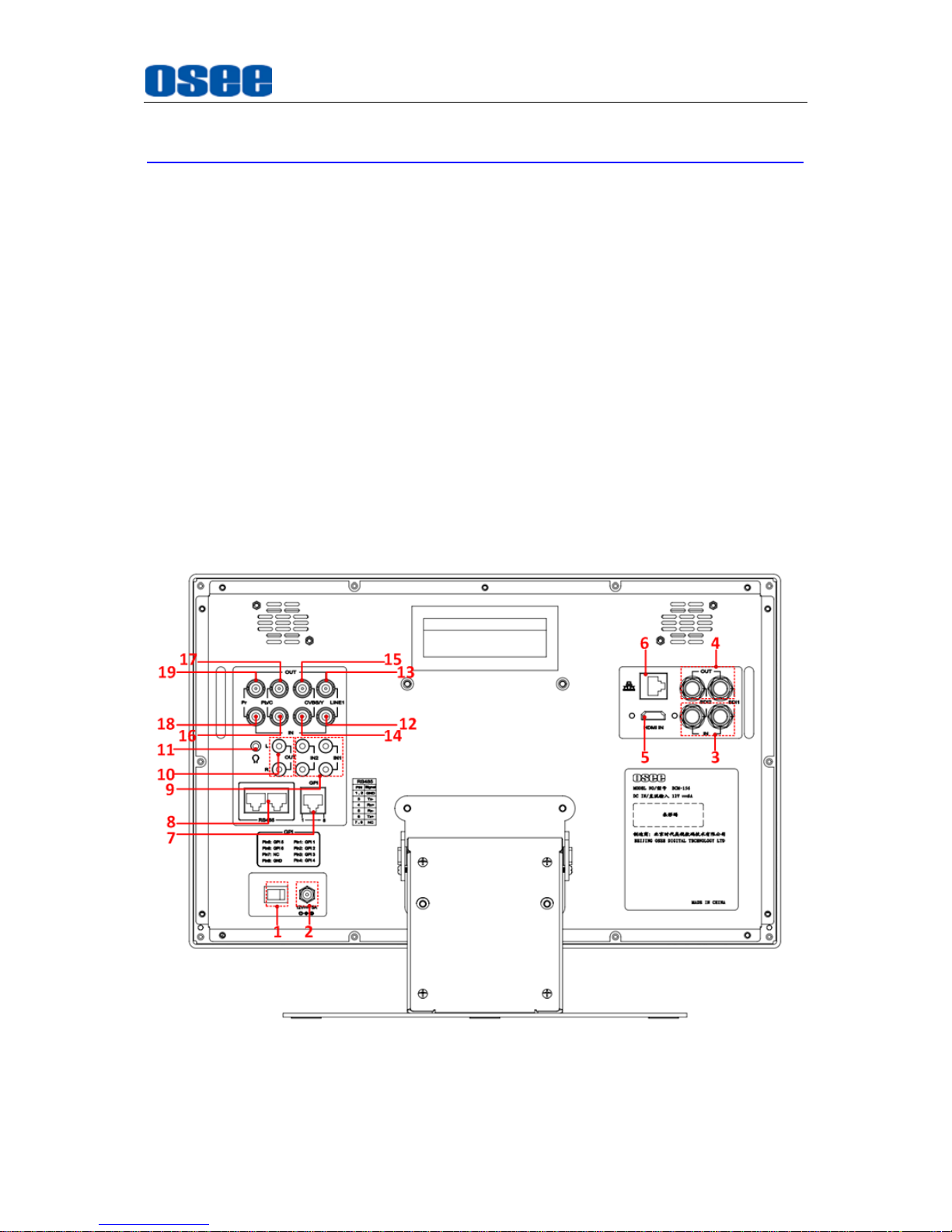
The real panel of LCM156-E is shown as below, there are various input and output
interfaces at the rear panel of LCM156-E monitor.
Parts and Functions
Figure 3.2-1 The Rear Panel of LCM156-E Monitor
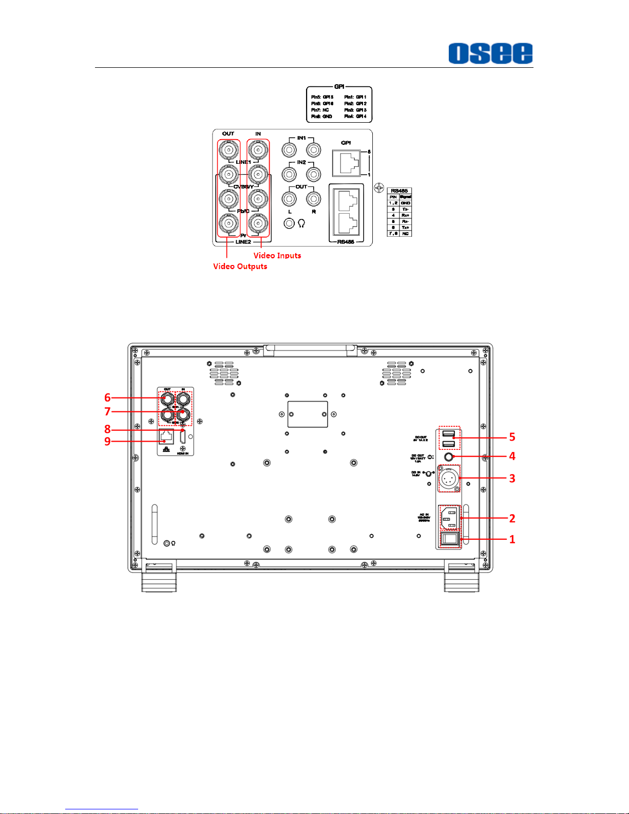
The interfaces numbered from 1 to 19 in red dotted rectangle are described as
Page 20
Locations and Function of Parts and Control
14
follows:
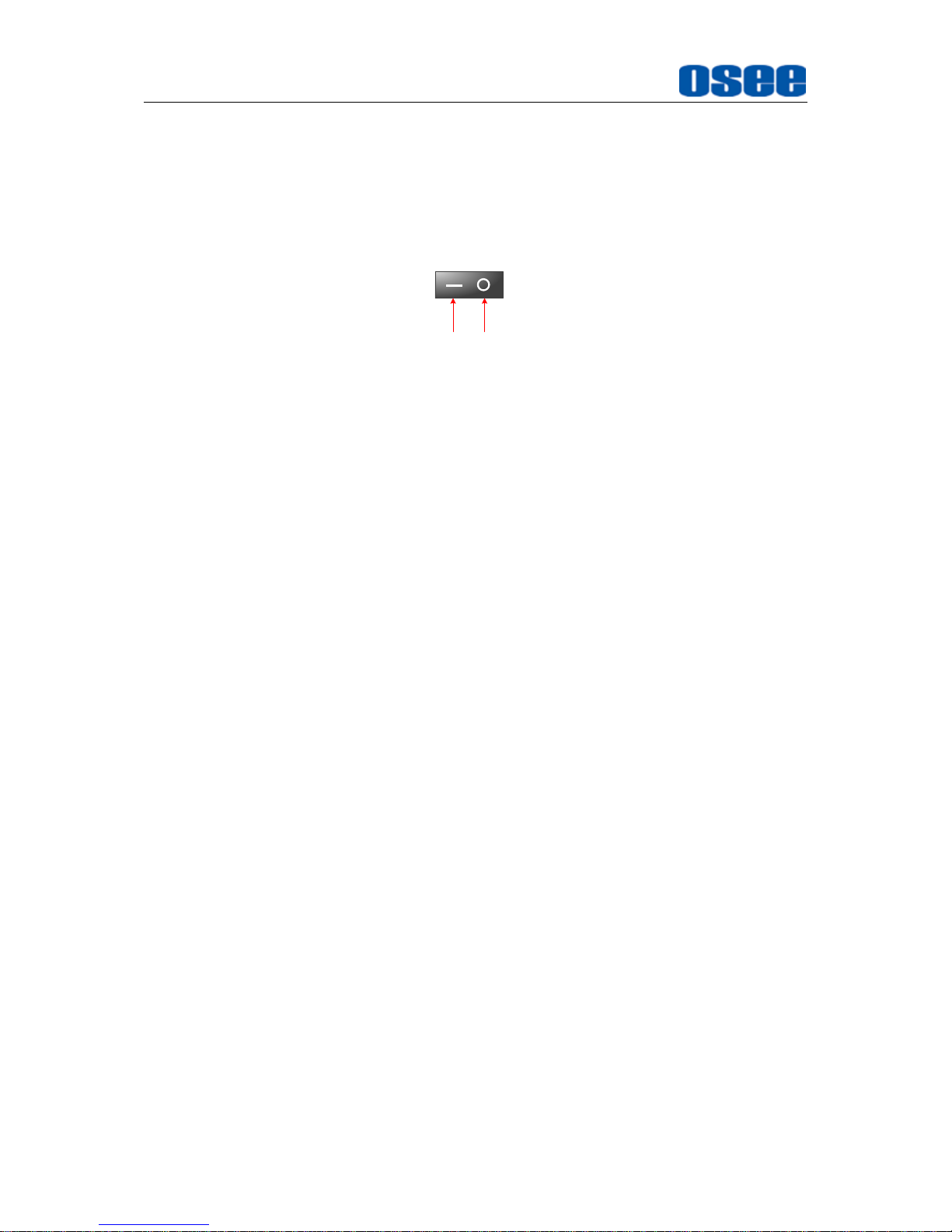
1. Power Switch
Press this part to switch on or switch off the power.
Push the button to the “-” icon to switch on the power.
Push the button to the “” icon to switch off the power.
ON OFF
2. Power Input
Plug the power supply to this interface to provide power to the device.
The specification is 12V5ADC.
3. SDI1 IN, SDI2 IN(BNC)
Two SDI signal input interfaces, support multiple format HD/3G-SDI inputs.
4. SDI1 OUT, SDI2 OUT(BNC)
Two SDI signal output interfaces.
5. HDMI IN(HDMI)
One HDMI signal input interface, HDMI Type-A connector, support HDMI or DVI
signal.
6. Ethernet(RJ-45)
A 10/100M Ethernet interface. Provide connection to a computer for external
control.
7. GPI interface(RJ-45)
Reserved and not defined.
8. RS485 (RJ-45)
Reserved and not defined.
9. Line IN(Unbalanced signal RCA connector)
Two pairs of analog audio stereo input interfaces: AUDIO IN1 L, AUDIO IN1 R,
AUDIO IN2 L, AUDIO IN2 R.
Connect to the audio outputs of external device.
10. L OUT, R OUT(RCA)Audio Output
Two audio output interfaces: AUDIO OUTPUT L, AUDIO OUTPUT R.
Output the analog stereo signal. The output audio can be changed in
AUDIO
settings.
11. Headphone Output Connector (3.5mm stereo Jack)
Page 21

Locations and Function of Parts and Control
15
12. LINE1 IN
A composite analog video input
interface.
13. LINE1 OUT
A composite analog video output
interface.
14. LINE2(CVBS/Y) IN
A composite analog video input
interface.
Feed the composited LINE2, or
component Y signal.
15. LINE2(CVBS/Y) OUT
A composite analog video output
interface.
Output the composited LINE2, or
component Y signal.
16. LINE2(Pb/C) IN
A component analog video input
interface.
Feed the component Pb, or
component C signal.
17. LINE2(Pb/C) OUT
A component analog video output
interface.
Output the component Pb, or
component C signal.
18. LINE2(Pr) IN
A component analog video input
interface.
Feed the component Pr signal.
19. LINE2(Pr) OUT
A component analog video output
interface.
Output the component Pr signal.
INPUT/OUTPUT VIDEO Connection Method
It provides two pairs of Composited Video input/output interfaces(LINE1, LINE2),
and a group of component signals(YPbPr, Y/C), the Y/C signal is also called as
S-Video. It will transmit different component signal according to the corresponding
signal interfaces.
As shown in Figure 3.2-2, the relationship of the signal sources and the interfaces
are shown as in Table 3.2-1:
Table 3.2-1 The Relationship of the Signal Sources and Input/output
Interfaces
Signal Source
Video Input Interfaces
Video Output Interfaces
LINE1
LINE1 IN
LINE1 OUT
LINE2(CVBS)
LINE2(CVBS/Y) IN
LINE2(CVBS/Y) OUT
LINE2(Y/C)
LINE2(CVBS/Y) IN
LINE2(Pb/C) IN
LINE2(CVBS/Y) OUT
LINE2(Pb/C) OUT
LINE2(YPBPR)
LINE2(CVBS/Y) IN
LINE2(Pb/C) IN
LINE2(Pr) IN
LINE2(CVBS/Y) OUT
LINE2(Pb/C) OUT
LINE2(Pr) OUT
Page 22
Locations and Function of Parts and Control
16
Figure 3.2-2 Video Input/Output Interfaces
The real panel of LCM170-E is as same as the LCM230-E’s, as shown below:
Figure 3.2-3 The Rear Panel of LCM170-E Monitor
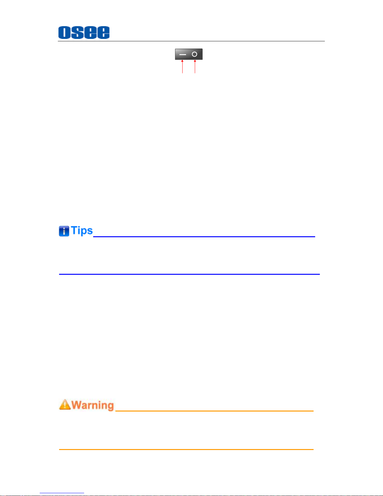
1. Power Switch
Press this part to switch on or switch off the power.
Push the button to the “-” icon to switch on the power.
Push the button to the “” icon to switch off the power.
Page 23
Locations and Function of Parts and Control
17
ON OFF
2. Power Input-AC IN
Plug the power supply to this interface to provide power to the device.
The specification is 100~240V 50/60Hz AC.
3. Power Input- DC IN 14.5V
One DC input interface from battery powered, 14.5V DC.
4. Power Output-DC OUT 12V/BATT 1.5A
One DC output interface, 1.5A DC. This interface provides a LEMO two core
socket of 1.5A current limichut. When using AC power supply, the output
voltage is 12V, and when using battery powered, the output voltage is
consistent with the output voltage of battery.
5. Power Output-DC OUT 5V 1AX2
Two DC output interfaces, 5V1A DC.
The
two DC OUT interfaces
only provide power supply of 1A current limit,
without data communication service.
6. SDI1 IN, SDI2 IN(BNC)
Two SDI signal input interfaces, support multiple format HD/3G-SDI inputs.
7. SDI1 OUT, SDI2 OUT(BNC)
Two SDI signal output interfaces.
8. HDMI IN(HDMI)
One HDMI signal input interface, HDMI Type-A connector, support HDMI or DVI
signal.
9. Ethernet(RJ-45)
A 10/100M Ethernet interface. Provide connection to a computer for external
control.
Only use the adapter and the power cord specified by the manufacture for your
safety!
Page 24

Locations and Function of Parts and Control
18
3.3 Supported Signal Format
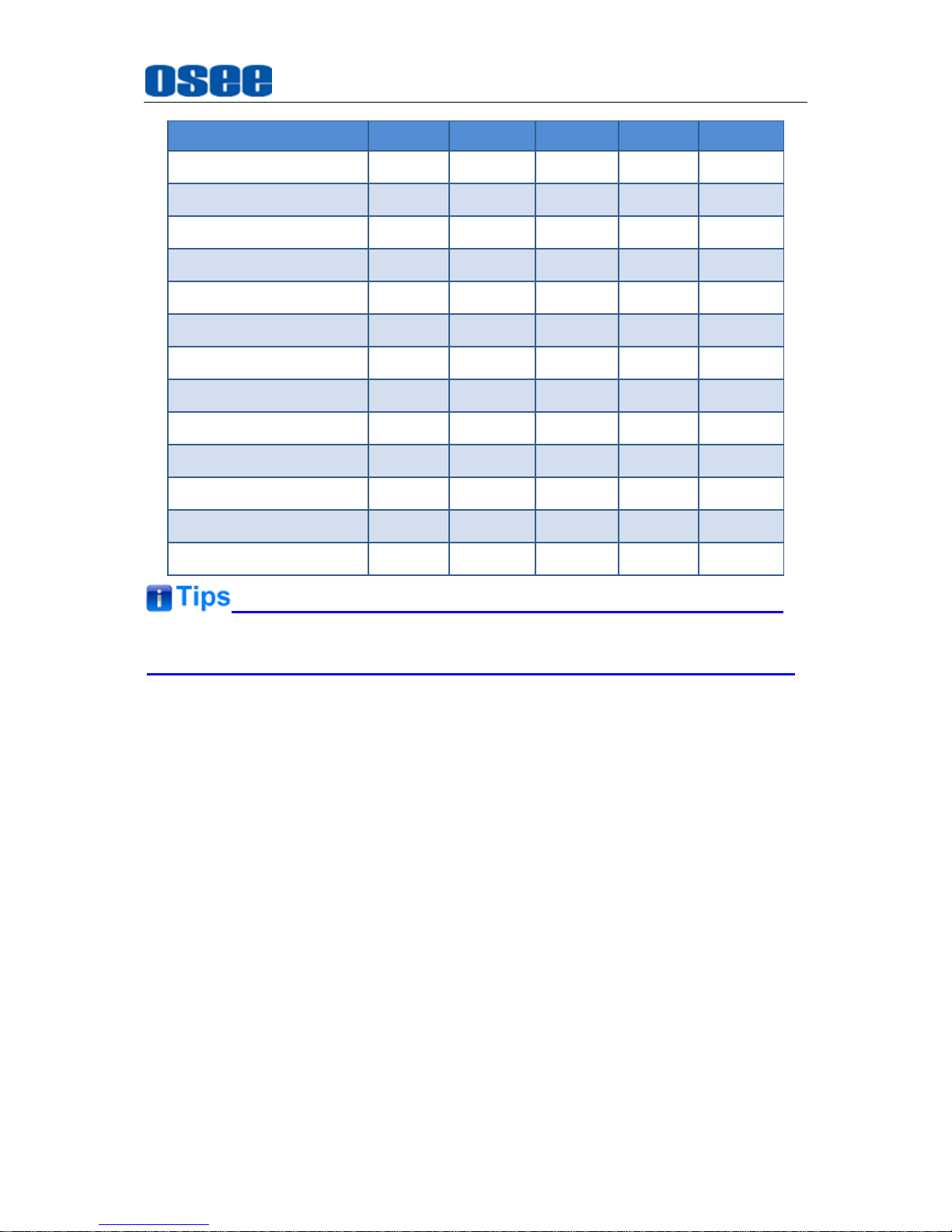
The supported signal format for this device is as shown in Table 3.3-1:
Table 3.3-1 Supported Signal Format
SDI
VIDEO1
HDMI
YC
YPBPR
PAL
NTSC
720P24/23.98
720P25
720P30/29.97
720P50
720P60/59.94
1080SF24/23.98
1035I60/59.94
1080I50
1080I60/59.94
1080P24/23.98
1080P25
1080P30/29.97
1080P50
1080P60/59.94
2048X1080PSF24/23.98
2048X1080PSF25
2048X1080PSF30/29.97
2048X1080P24/23.98
2048X1080P25
2048X1080P30/29.97
2048X1080P48/47.94
1
VIDEO: The VIDEO in the head of this table is refer to CVBS signal, that is, the signal through the
LINE1(CVBS) or LINE2(CVBS) interface.
Page 25
Locations and Function of Parts and Control
19
SDI
VIDEO1
HDMI
YC
YPBPR
2048X1080P50
2048X1080P60/59.94
VGA(640X480)
SVGA(800X600)
XGA(1024X768)
SXGA(1280X1024)
WXGA(1360X768)
WXGA+(1440X900)
WXGA+(1400X1050)
UXGA(1600X1200)
UXGA+(1680X1050)
WUXGA(1920X1080)
WUXGA(1920X1200)
LCM170-E and LCM230-E only support SDI and HDMI.
Page 26

20
Page 27
Menu Operations
21
Chapter 4 Menu Operations
This chapter describes the structure and functionality of the On-Screen Menu, and
introduces how to modify and customize the menu settings.
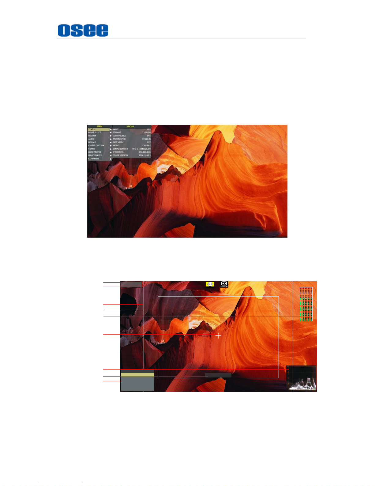
The Main Menu consists of the following sections: STATUS, INPUT SELECT,
MARKER, AUDIO, DISPLAY, CLOSED CAPTION, CONFIG, LOOK PROFILE,
FUNCTION KEY and KEY INHIBIT, as shown in Figure5-1.
Figure 5-1 On-Screen Menu
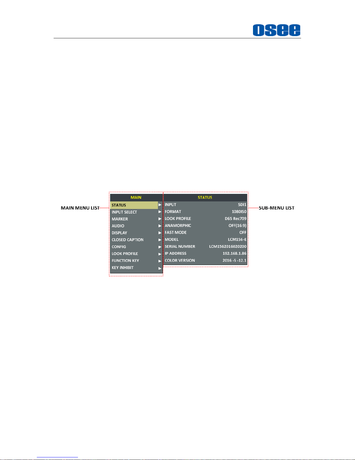
The features on the screen are as shown in Figure 5-2:
SDI1
1080I59.94
--:--:--:--
1 2 3 4 5 6 7 8
Status Information
Audio Meter
Center Marker
Timecode
Safe Marker
Area Marker
Adjust Menu
Wave Form
AFD CC
F1 OFFFOCUS ASSIST
F2 OFFNATIVE
FUNCTION
F3 OFF(16:9)ANAMORPHIC
F4
OFF
FALSE COLOR
F5 OFF
PBP
Figure 5-2 Features of LCM156-E Monitor
Status Information: it displays the input channel and signal format. Set by
DISPLAY Status Display item.
Page 28
Menu Operations
22
AFD Information: Set by DISPLAY AFD Display item.
CC Information: Set by CLOSED CAPTION menu.
Marker Information: including Area Marker, Center Marker and Safety Maker, and
set by Marker menu.
Audio Meter: Set by Audio menu.
Wave Form: Set by DISPLAY menu.
Time Code: Set by DISPLAY menu.
FUNCTION Menu: it will pop up when pressing the F1~F5 button, and set by
FUNCTION menu.
Please refer to the corresponding sections for the details in this chapter.
4.1 Main Menu
Display the Main Menu
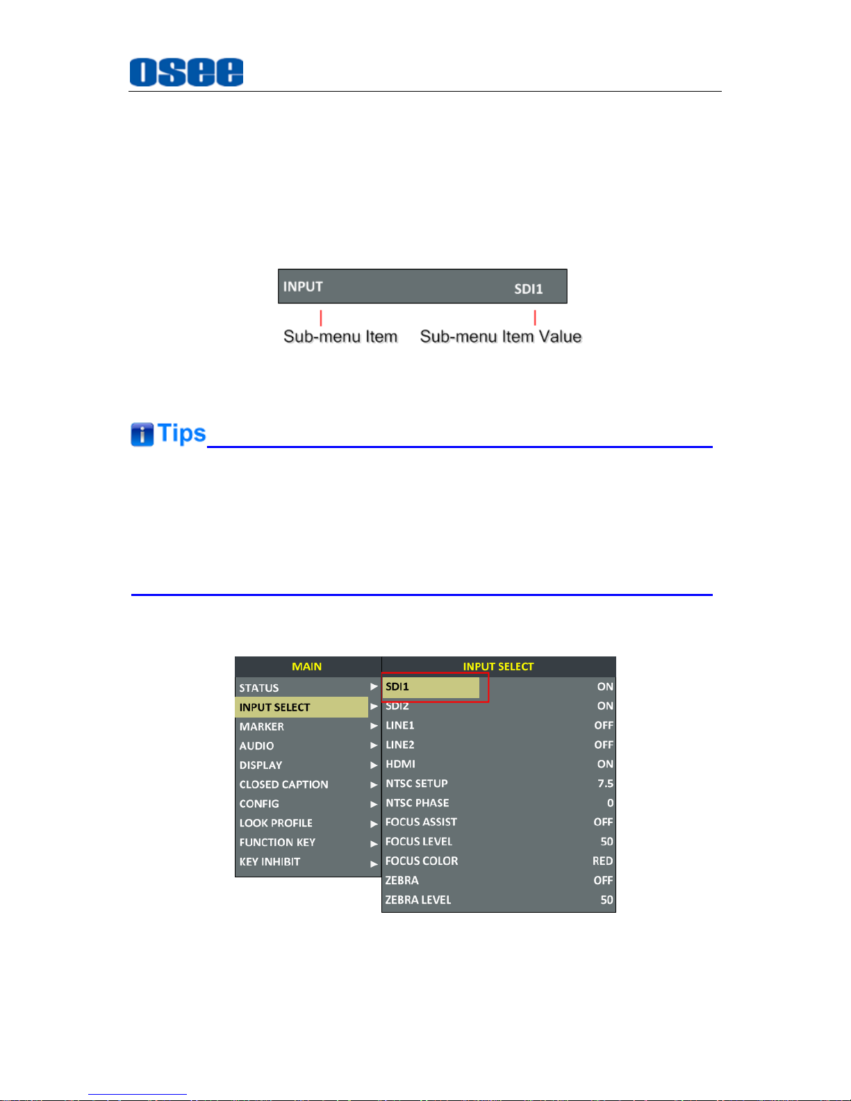
Press the MENU button to display the Main Menu at the top left corner of the screen,
as shown in Figure 4.1-1:
Figure 4.1-1 the Structure of the Main Menu
The menu interface is divided into two parts: Main Menu List and Sub-menu list.
Menu Control
You may control these various functions using MENU, UP, DOWN and ENTER
buttons. Follow the instructions below:
Press UP or DOWN to navigate to a menu item, then, press Enter button to enter into
the sub-menu list of the selected item.
1. Press
MENU
button to display the MAIN Menu.
2. Press UP or
DOWN
button to move the control icon to your target menu item
in main menu list, here, the control icon is a highlight yellow rectangle which is
used to label the current active selection.
3. Press
Enter
button to access the sub-menu list of the selected main menu,
Page 29
Menu Operations
23
and press UP or
DOWN
button again to select your target sub-menu item which
you want to modify its value.
4. Press
Enter
button to confirm the selection of your target sub-menu item, and
press UP or
DOWN
button to adjust its value from its sub-menu item list.
5. Press
Enter
button to save the value, otherwise, press
Menu
button to give up
the modification or selection, and return to the previous menu, and if there is no
previous menu, it will clear the MAIN Menu.
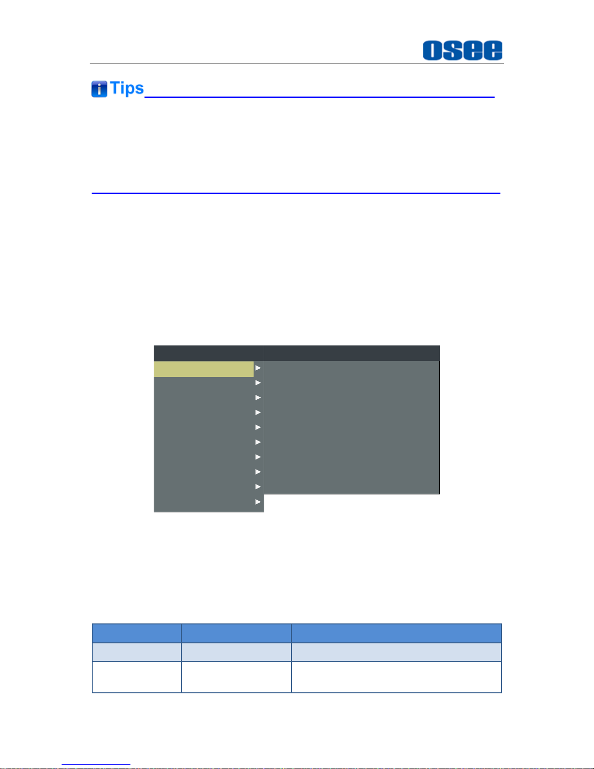
Figure 4.1-2 the Sub-menu Value List
The control icon is displayed as a highlight yellow rectangle at the background of
the current active item.
The item displayed in blue can't be accessed currently. You can access the item
which is displayed in white except the STATUS settings.
For example: choose the INPUT SELECTSDI1 item, the control icon is displayed
as shown in Figure 4.1-3:
Figure 4.1-3 A Sub-menu Item Is Selected
Page 30
Menu Operations
24
If the
KEY INHIBITKEY INHIBIT
is set to be ON, all items will not be displayed
except
KEY INHIBIT
item. To change any one of the items, you should turn the
KEY INHIBITKEY INHIBIT
to be OFF first. Refer to "4.1.10 KEY INHIBIT
Menu" for the details.
The following will introduce the contents and functionality of these menu items in
sorts.
4.1.1 STATUS Menu
The STATUS menu items are not configurable settings, but provide important
information of the monitor, such as input signal resolution and frame rate, active color
space, model, serial number, and IP Address, etc.
Press MENU button to display the Main Menu, and the STATUS menu items are as
shown in Figure 4.1-4:
CLOSED CAPTION
INPUT SELECT
MARKER
AUDIO
DISPLAY
CONFIG
LOOK PROFILE
FUNCTION KEY
MAIN
MODEL
INPUT
FORMAT
LOOK PROFILE
ANAMORPHIC
FAST MODE
SERIAL NUMBER
IP ADDRESS
COLOR VERSION
STATUS
LCM156-E
SDI1
1080I50
D65 Rec709
OFF(16:9)
OFF
LCM1562016020200
192.168.1.86
2016 -5 -12.1
STATUS
KEY INHIBIT
Figure 4.1-4 STATUS Menu
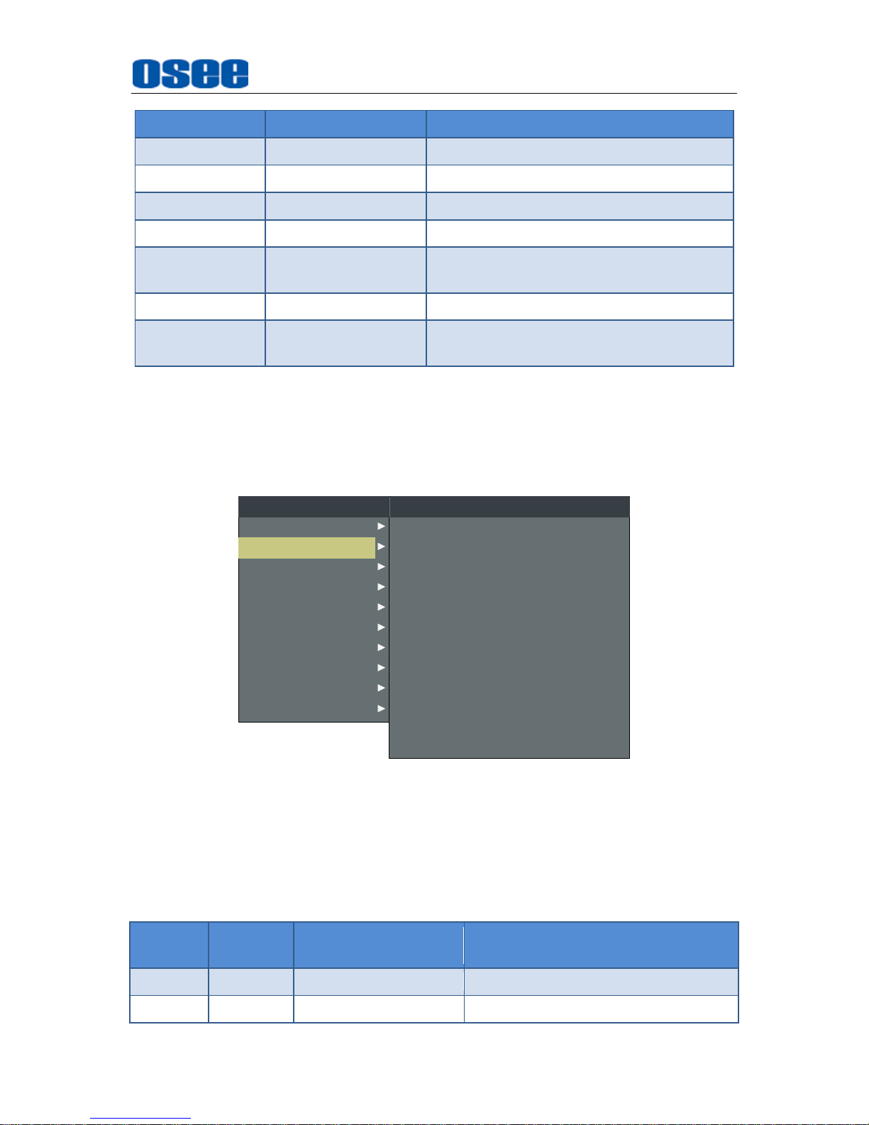
The relationship of Items, Default Value, Domain Range and Description of the
sub-item is as shown in Table 4.1-1:
Table 4.1-1 The Description of STATUS Menu Items
Items
Default Value
Description
INPUT
SDI1
Show the current Input interface
FORMAT
1080I50
Show the signal resolution and frame rate
of the current input
Page 31
Menu Operations
25
Items
Default Value
Description
LOOK PROFILE
D65 Rec709
Show the LOOK PROFILE Feature.
ANAMORPHIC
16:9
Show the aspect ratio of the picture.
FAST MODE
OFF
Show the fast mode.
MODEL
LCM156-E
Show the production model.
SERIAL
NUMBER
LCM1562016020200
Show the serial number.
IP ADDRESS
192.168.1.86
Show the IP address.
COLOR
VERSION
2016-5-12.1
Show the color version according to its
adjusted date.
4.1.2 INPUT SELECT Menu
The INPUT SELECT menu items are used to enable the input signals, NTSC level
and phase, FOCUS settings and ZEBRA settings, as shown in Figure 4.1-5:
NTSC SETUP
SDI1
SDI2
LINE1
LINE2
HDMI
NTSC PHASE
INPUT SELECT
7.5
ON
ON
OFF
OFF
ON
0
ZEBRA
FOCUS ASSIST
FOCUS LEVEL
FOCUS COLOR
ZEBRA LEVEL
OFF
OFF
50
RED
50
CLOSED CAPTION
MARKER
AUDIO
DISPLAY
CONFIG
LOOK PROFILE
FUNCTION KEY
MAIN
STATUS
KEY INHIBIT
INPUT SELECT
Figure 4.1-5 INPUT SELECT Menu
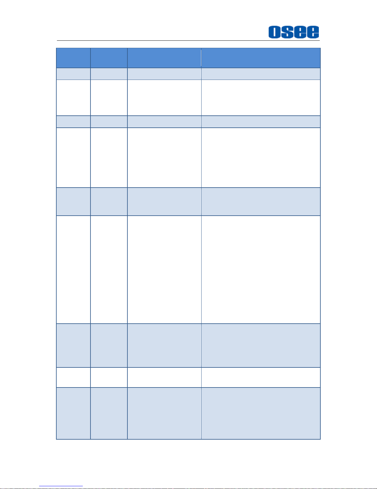
The relationship of Items, Default Value, Domain Range and Description of the
sub-item is as shown in Table 4.1-2:
Table 4.1-2 The Description of INPUT SELECT Menu Items
Items
Default
Value
Domain Range
Description
SDI1
ON
ON/OFF
Enable/Disable SDI1 input.
SDI2
ON
ON/OFF
Enable/Disable SDI2 input.
Page 32
Menu Operations
26
Items
Default
Value
Domain Range
Description
LINE1
OFF
ON/OFF
Enable/Disable LINE1 input.
LINE2
OFF
CVBS
LINE2(Y/C)
LINE2(YPBPR)
OFF
Enable/Disable LINE2 input, and
select the input source format.
HDMI
ON
ON/OFF
Enable/Disable HDMI input.
NTSC
SETUP
7.5
0: the 0 setup level
is used mainly in
Japan.
7.5: the 7.5 setup
level is used
mainly in North
America.
Set the black level of NTSC video to 0
setup or 7.5 IRE setup.
NTSC
PHASE
0
-50~50
Set the NTSC phase level, and this
item is available only when NTSC
format signal is input.
FOCUS
ASSIST
OFF
OFF
GRAY: Turn the
image into gray
mode, and
displays the edge
of images with
color selected in
FOCUS COLOR.
COLOR: Displays
the edge of
images with color
selected in
FOCUS COLOR.
Enable/Disable the focus assist
function, and set focus assist mode.
When the difference of the edges
exceeds the reference value (FOCUS
LEVEL), the edge detected will be in
colorful feature set by FOCUS
COLOR.
FOCUS
LEVEL
50
0~100
Set the edge difference value
between the edges in an image, and
take this value as the reference
value. Larger value means more
detail detection.
FOCUS
COLOR
RED
RED/GREEN/BLUE
Set the color for the detected edge of
images.
ZEBRA
OFF
ON/OFF
Enable/Disable the zebra function
that will compare the signal
luminance with the
ZEBRA LEVEL
,
and fill the relevant image area
whose luminance is higher than the
ZEBRA LEVEL
with a zebra pattern.
Page 33
Menu Operations
27
Items
Default
Value
Domain Range
Description
ZEBRA
LEVEL
50
0~100
Set the reference level of detecting
luminance.
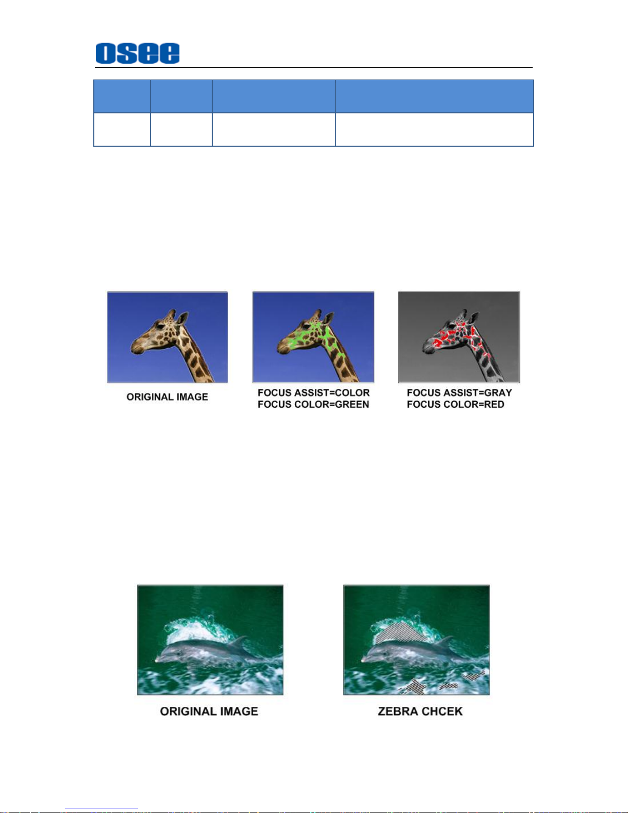
FOCUS ASSIST
The FOCUS ASSIST function is used to display images on the screen with intensified
edge to help camera focus operation. The intensified edges are those areas whose
difference value exceeds the reference focus level (FOCUS LEVEL), and the
intensified edge are displayed in the designated color set by FOCUS COLOR.
For example, set the FOCUS LEVEL as 80, the compared results between COLOR
mode and GRAY mode are as shown Figure 4.1-6, the intensified edges are in the
designated color.
Figure 4.1-6 Illustration for FOCUS ASSIST Function
ZEBRA
The ZEBRA function is used to display images on the screen with a zebra pattern to
adjust the camera exposure parameter. It will compare the signal luminance with the
ZEBRA LEVEL, and fill the relevant image area whose luminance is higher than the
ZEBRA LEVEL with a zebra pattern.
For example, set the ZEBRA LEVEL as 80, the compared results are as shown in
Figure 4.1-7, the special area is filled with a zebra pattern.
Figure 4.1-7 Illustration for LUMA ZOOM CHECK Function
Page 34
Menu Operations
28
LINE2
Select input source format for LINE2 among LINE2(CVBS), LINE2(Y/C) and
LINE2(YPBPR).
For LINE2(CVBS) interface, LINE2(Y/C) interface and LINE2(YPbPr) interface share
the same group of physical interfaces, select the signal source format for LINE2
according to the cable connection mode.
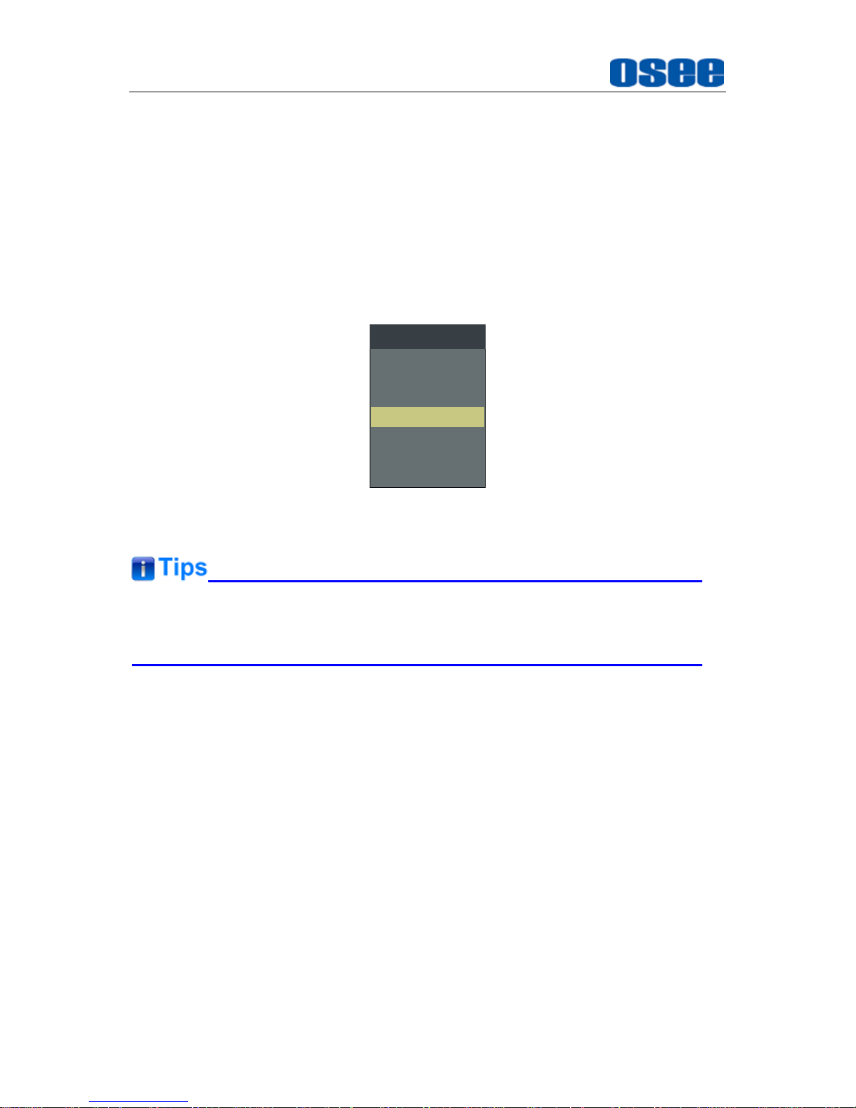
To select a signal source format for LINE2, you can set the menu item INPUT
SELECTLINE2 to be LINE2(CVBS), LINE2(Y/C) or LINE2(YPBPR), in addition,
press INPUT button to pop up the SOURCE MENU for LINE2 selection.
SDI1
LINE1(CVBS)
LINE2(CVBS)
LINE2(Y/C)
SOURCE
SDI2
LINE2(YPBPR)
HDMI
Figure 4.1-8 LINE2 SWITCHING in SOURCE MENU
NTSC PHASE
item is available only when NTSC format signal is input, while,
only the LINE1 and LINE2 (CVBS) interface support NTSC format signal.
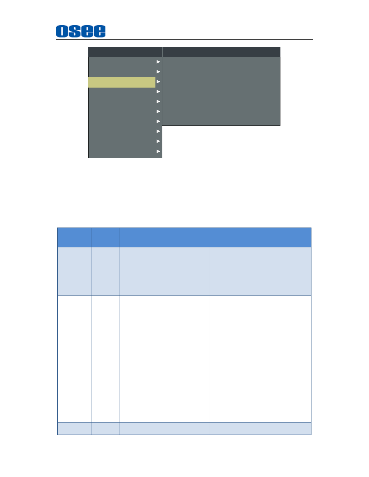
4.1.3 MARKER Menu
The MARKER menu items are used to display various markers and set the marker
preference. It provides Area Marker, Center Marker, Safety Marker and Cross
Hatch, while, you can set the aspect ratio of safety area, the darkness outside of the
safety area, etc. These markers can be flexibly controlled by the following settings, as
shown in Figure 4.1-9:
Page 35
Menu Operations
29
MARKER MAT
MARKER
AREA MARKER
CENTER MARKER
SAFETY MARKER
MARKER LEVEL
CROSS HATCH
MARKER
OFF
OFF
OFF
OFF
OFF
1
OFF
CLOSED CAPTION
INPUT SELECT
AUDIO
DISPLAY
CONFIG
LOOK PROFILE
FUNCTION KEY
MAIN
STATUS
KEY INHIBIT
MARKER
Figure 4.1-9 MARKER Menu
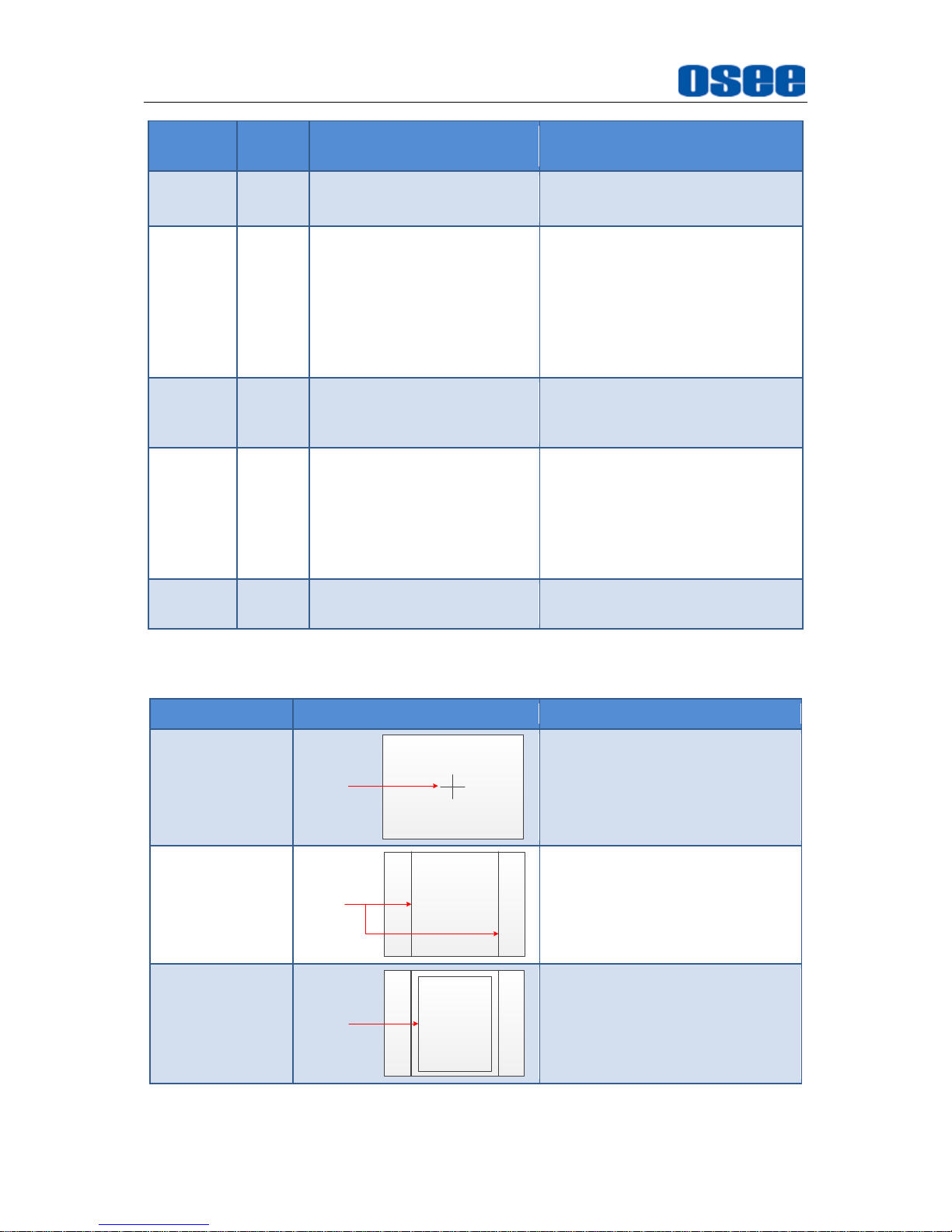
The relationship of Items, Default Value, Domain Range and Description of the
sub-item is as shown in Table 4.1-3:
Table 4.1-3 The Description of MARKER Menu Items
Items
Default
Value
Domain Range
Description
MARKER
OFF
OFF/ON
Set ON to display the markers
and OFF not to display.
It is the master switch for Area
Marker, Center Marker and
Safety Marker.
AREA
MARKER
OFF
When the display aspect is
16:9, select the following
aspect ratio:
OFF: close area marker
4:3
15:9
14:9
13:9
1.85:1
2.35:1
When the display aspect is
4:3, select the following
aspect ratio:
OFF: close area marker
16:9
Select the aspect ratio of the
Area Marker.
CENTER
OFF
OFF/ON
Set whether to display a cross
Page 36
Menu Operations
30
Items
Default
Value
Domain Range
Description
MARKER
marker which represents the
center of the image.
SAFETY
MARKER
OFF
OFF
80%
85%
88%
90%
93%
95%
Select to display and control the
size of the safety area, that is,
the effective screen area.
MARKER
LEVEL
1
1: 50%
2: 75%
3: 100%
Set the luminance to display
Safety Marker, Center Marker,
Area Marker and Cross Hatch.
MARKER
MAT
OFF
OFF: Normal
background, use line for
area marker edge only
HALF: 50% Background
darkness
BLACK: all black
Set the darkness degree of the
mat area. This item darkens the
area of the outside of marking
area.
CROSS
HATCH
OFF
OFF/ON
Set whether to show the cross
hatch.
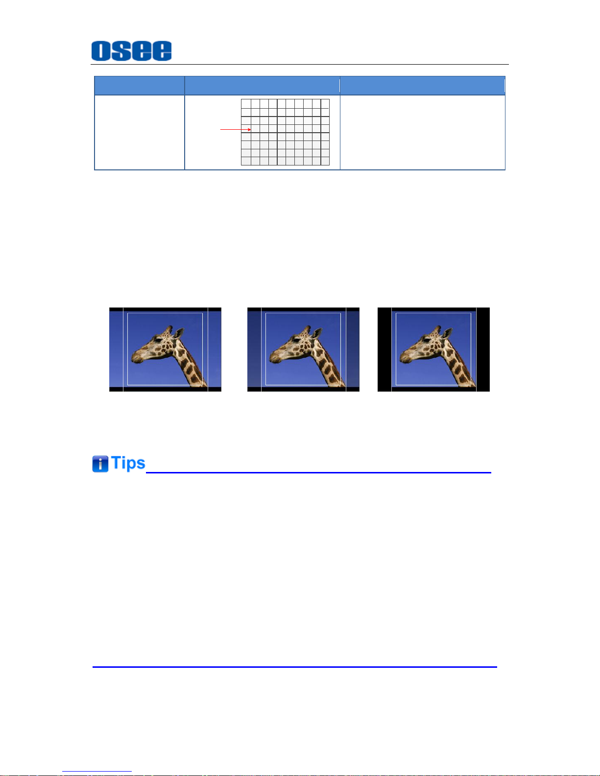
MARKERS
CENTER MARKER, AREA MARKER, SAFETY MARKER, CROSS HATCH.
Marker
Illustration
Description
CENTER
MARKER
CENTER
MARKER
This marker enables easier
checking the center portion’s
focus.
AREA MARKER
AREA
MARKER
This marker displays two lines to
identify an area with a specified
aspect ratio.
SAFETY
MARKER
SAFETY
MARKER
This marker displays a rectangle
to identify the safety area with a
specified percentage in Area
Marker.
Page 37
Menu Operations
31
Marker
Illustration
Description
CROSS HATCH
CROSS
HATCH
This marker displays multiple
vertical and horizontal lines to
help when users check the
composition of a picture.
MARKER MAT
The Marker Mat darkens the outside area of the marker setting display area. When
Marker Mat is set as OFF, the outside area of marker is transparent. When Marker
Mat is set as HALF, the outside area of marker is 50% blackness of the background.
When Marker Mat is set as BLACK, the outside area of marker is totally in black.
For example, set ASPECT as 16:9, AREA MARKER as 4:3, and SAFETY AREA as
95%, then, the comparison of these three MARKER MATs are as shown in Figure
4.1-10:
MARKER MAT=OFF MARKER MAT=HALF MARKER MAT=BLACK
Figure 4.1-10 MARKER MAT
All markers will be hidden in the following modes though the corresponding
marker is enabled (the value is not OFF): NATIVE, PBP.
The AREA MARKER, CENTER MARKER and SAFETY MARKER feature are
available only when the MARKER item is set to ON, and the color of the marker
lines are white.
The safety marker area will change with the area marker.
The cross hatch lines will display only in the single image or in PIP mode when
CROSS HATCH
is ON.
Page 38
Menu Operations
32
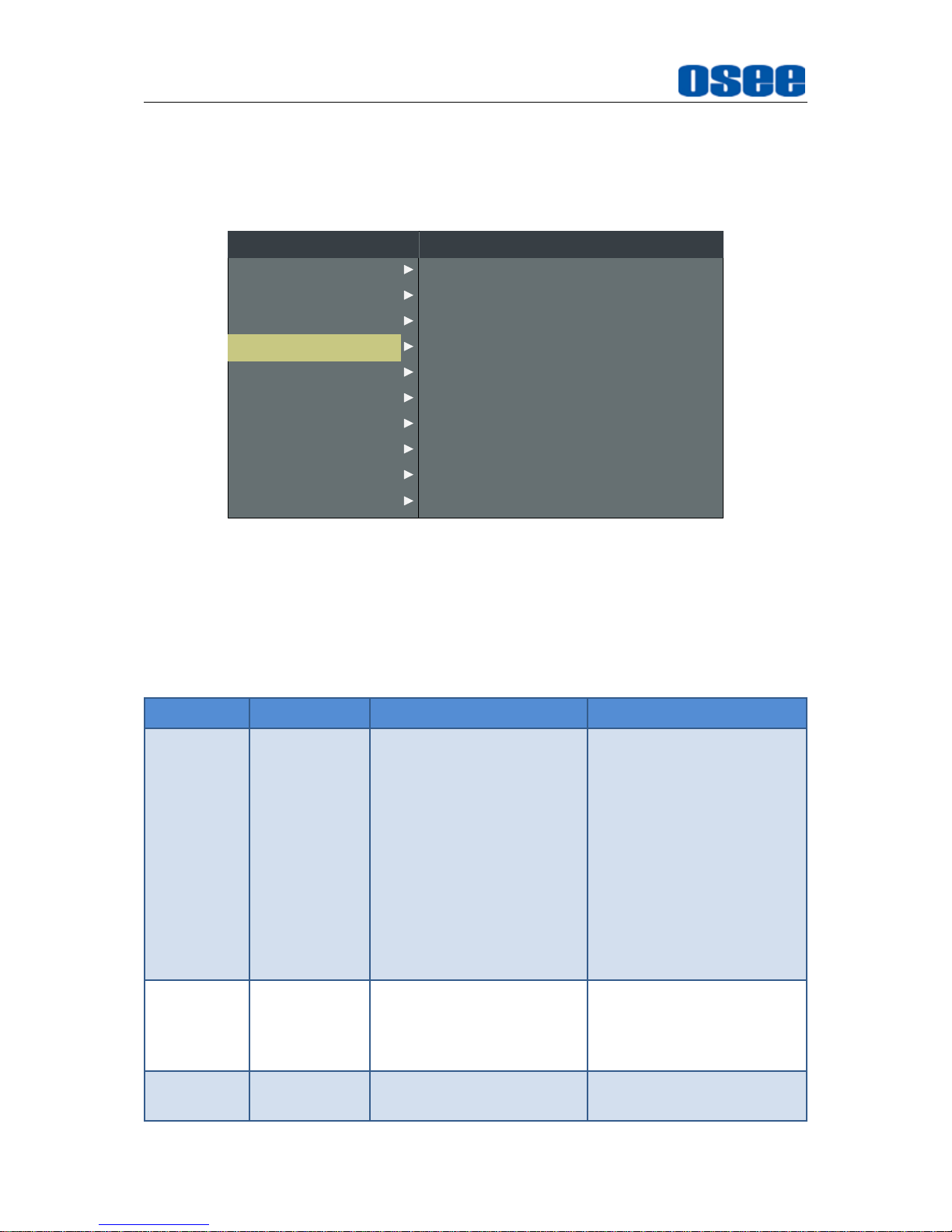
4.1.4 AUDIO Menu
The AUDIO menu items are used to set your audio source, audio level meter display
preferences, the menu items are as shown in Figure 4.1-11:
METER DIRECTION
AUDIO SOURCE
SPEAK OUT L
SPEAK OUT R
AUDIO METER
METER SELECT
METER POSITION
METER DIS MODE
REF LEVEL
AUDIO
HORIZONTAL
EBD
EBD CH1
EBD CH1
OFF
CH1-2
TOP
MODE1
-20dB
OVER LEVEL -10dB
CLOSED CAPTION
INPUT SELECT
MARKER
DISPLAY
CONFIG
LOOK PROFILE
FUNCTION KEY
MAIN
STATUS
KEY INHIBIT
AUDIO
Figure 4.1-11 AUDIO Menu
The relationship of Items, Default Value, Domain Range and Description of the
sub-item is as shown in Table 4.1-4:
Table 4.1-4 The Description of AUDIO Menu Items
Items
Default Value
Domain Range
Description
AUDIO
SOURCE
EBD
EBD: output an audio
signal embedded in
SDI or HDMI signal.
AUDIO1: output an
audio signal that
comes from the
AUDIO IN1 interface.
AUDIO2: output an
audio signal that
comes from the
AUDIO IN2 interface
UNDEF: no sound
Select an audio format to
output from speaker,
headphone jack or AUDIO
OUTPUT interface.
SPEAK
OUT L
EBD CH1
When the audio source is
set as EBD, the range of
this item is EBD CH1~
EBD CH16.
Set the embedded audio
channel for the left speaker
when SDI signal is input.
SPEAK
OUT R
EBD CH2
When the audio source is
set as EBD, the range of
Set the embedded audio
channel for the right
Page 39
Menu Operations
33
Items
Default Value
Domain Range
Description
this item is EBD CH1~
EBD CH16.
speaker when SDI signal is
input.
AUDIO
METER
OFF
OFF/ON
Set whether to display the
audio level meter.
METER
SELECT
CH1-2
CH1-2
G1
G2
G3
G4
G1+G2
G1+G3
G1+G4
G2+G3
G2+G4
G3+G4
G1-4
Used to select the audio
channels that will be
shown in the audio meter
display. Each G*
represents four channels,
and each CH* represents a
channel with specified
number.
METER
DIRECTION
HORIZONTAL
VERTICAL
HORIZONTAL
Used to set the displayed
direction of audio meter.
METER
POSITION
BOT LEFT/
BOTTOM
When METER
DIRECTION is set as
VERTICAL
, choose one of the
followings:
BOT LEFT: bottom left
BOT RIGHT: bottom
right
TOP RIGHT: top right
TOP LEFT: top left
When METER
DIRECTION is set as
HORIZONTAL, choose
one of the followings:
BOTTOM
TOP
Used to set the displayed
position of audio meter.
METER DIS
MODE
MODE1
MODE1: simple audio
meter
MODE2: audio meter
with channel number
MODE3: audio meter
with channel number
and dB value
Used to set the displayed
mode for audio meter.
REF LEVEL
-20dB
-20dB/-18dB
Set the reference level
OVER
LEVEL
-10dB
-10dB
-8dB
Set the overload level
Page 40

Menu Operations
34
Items
Default Value
Domain Range
Description
-6dB
-4dB
-2dB
AUDIO LEVEL METER
The appearance of Audio Level Meter is as shown in Figure 4.1-12:
Figure 4.1-12 Audio Level Meter
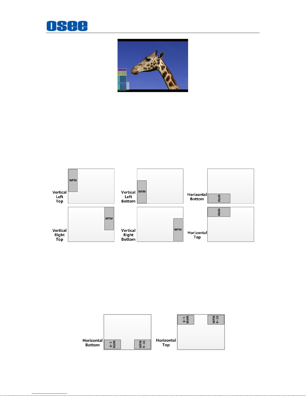
METER SELECT item and METER DIS MODE item control the operational
characteristics of Audio Metering, the former controls the amount of channels
displayed in a meter.
For example: As shown in Figure 4.1-13, the meter displays at the left of the screen
vertically, the METER SELECT is G1+G2, and the METER DIS MODE is MODE3,
you can see the meter displays audio channel numbers and audio values beside the
meter.
There are two white horizontal level lines in the white rectangle frame of audio meter,
the upper is the OVER LEVEL line, and the lower is the REFERENCE LEVEL line. If
the audio value is higher than the reference level, the audio bar over the reference
level line will display in yellow, and if the audio value is higher than the over level, the
audio bar over the OVER LEVEL line will display in red, thus you could observe the
exceeded part intuitively.
Page 41
Menu Operations
35
Figure 4.1-13 The Position of the Audio Meter On Screen
AUDIO LEVEL METER POSITION
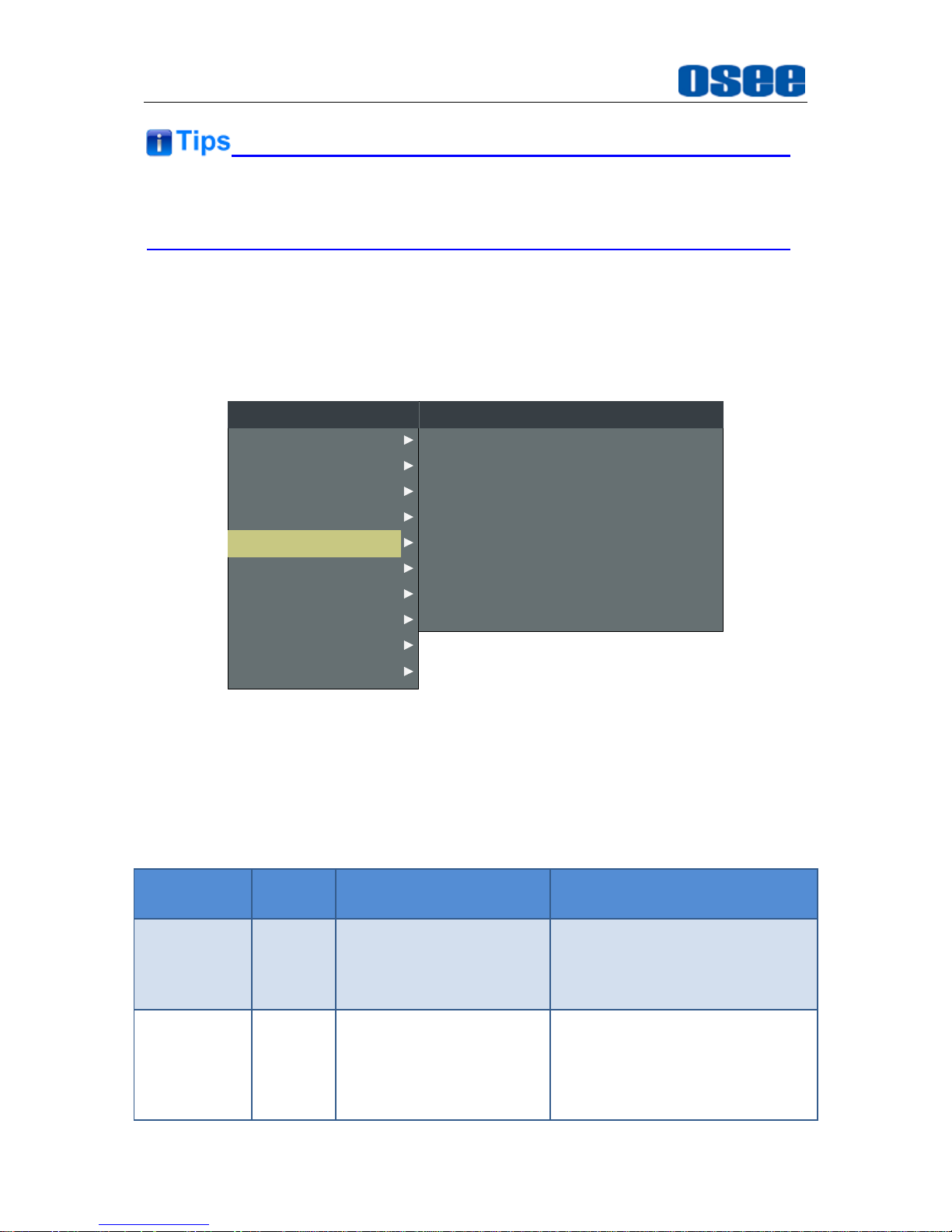
The position of AUDIO LEVEL Meter is controlled by METER DIRECTION and
METER POSITION, the position of the audio meter on the screen could be as follows:
TOP LEFT VERTICAL, TOP RIGHT VERTICAL, BOT LEFT VERTICAL, BOT
RIGHT VERTICAL, BOTTOM HORIZONTAL and TOP HORIZONTAL. The
illustrations of these positions are as shown in Figure 4.1-14:
Figure 4.1-14 the Positions of Audio Meter
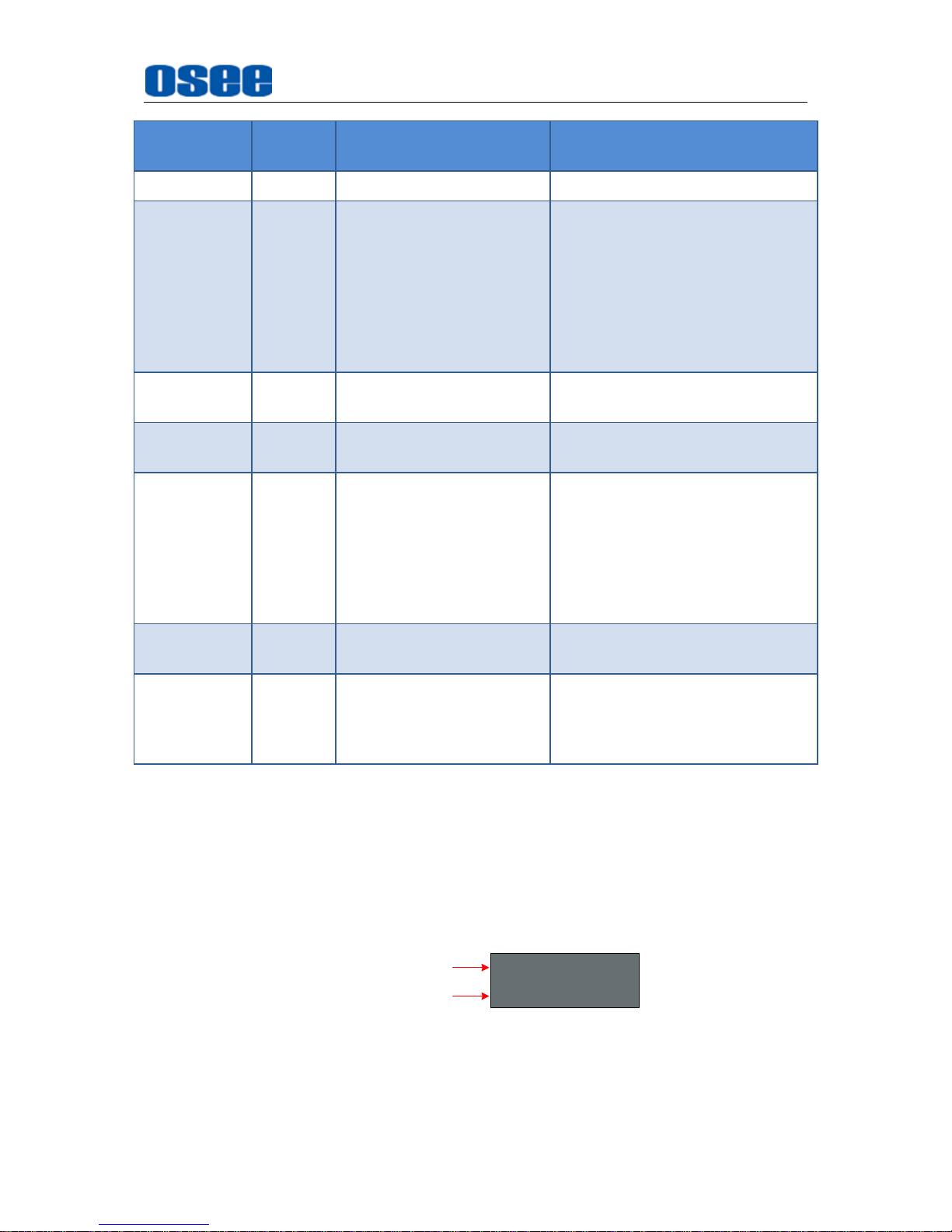
Particularly, if the METER SELECT item is set as G1-4, there will be 16 channels
displayed in audio meter, and if the METER DIRECTION is Horizontal, the audio
meter will display two meters separately on both sides of the screen. One displays 8
channels (1~8) on the bottom or top left of the screen, and the other displays 8
channels (9~10) on the bottom or top right of the screen, the bottom or top is decided
by METER POSITION, as shown in Figure 4.1-15:
Figure 4.1-15 the Positions of the 16-channels Meter
Page 42
Menu Operations
36
The prerequisite for the available settings of the display mode and the position of
audio meter is that the
AUDIO METER
is ON.
4.1.5 DISPLAY Menu
The DISPLAY menu items are used to set your status information, wave form, vector,
line wave, AFD and time code preference displayed on the screen, the menu items
are as shown in Figure 4.1-16:
STATUS DISPLAY
AFD DISPLAY
WFM POSITION
WAVE FORM TYPE
WAVE OVER LIMIT
WAVE UNDER LIMIT
WFM TRANS
DISPLAY
AUTO
OFF
LEFT
WAVE FORM
50
0
OPAQUE
TIME CODE OFF
CLOSED CAPTION
INPUT SELECT
MARKER
AUDIO
CONFIG
LOOK PROFILE
FUNCTION KEY
MAIN
STATUS
KEY INHIBIT
DISPLAY
Figure 4.1-16 DISPLAY SETUP Menu
The relationship of Items, Default Value, Domain Range and Description of the
sub-item is as shown in Table 4.1-5:
Table 4.1-5 The Description of DISPLAY SETUP Menu Items
Items
Default
Value
Domain Range
Description
STATUS
DISPLAY
AUTO
OFF/ON/AUTO
Set whether to display Status
information, including the
resolution and frame rate of the
source.
AFD
DISPLAY
OFF
OFF/ON
Set whether to activate AFD
information.
ON is an effective value to AFD
DISPLAY item only if the value of
STATUS DISPLAY is AUTO or
Page 43
Menu Operations
37
Items
Default
Value
Domain Range
Description
ON.
WFM FORM
TYPE
OFF
MODE1: WAVE
FORM+ VECT75
MODE2: WAVE
FORM+ VECT100
VECT100
VECT75
WAVE FORM
OFF
Switch the display mode among
mode1, mode2, vector100,
vector75 and wave form.
When the wave form is selected,
it will display the wave form, and
when the vector* is selected, it
will display the color component
of the image signal.
WFM
OVERLIMIT
100
50~100
Set the over limit of wave form.
WFM
UNDERLIMIT
0
0~50
Set the under limit of wave form.
WFM TRANS
OPAQUE
OPAQUE
TRANS1: the
transparency is 25%
TRANS2: the
transparency is 50%
TRANS3: the
transparency is 75%
Set the transparency of the wave
form/vector
WFM
POSITION
LEFT
LEFT: Left bottom
RIGHT: Right bottom
Set the displayed position for
wave form/vector.
TIME CODE
OFF
OFF
D-VITC
LTC
VITC
Set whether to display time code,
and set the time code display
mode.
STATUS INFORMATION
Set DISPLAYSTATUS DISPLAY item to be ON or Auto, it will display the Status
Information bar at the top left corner of the screen, and it displays the input channel
and signal format.
The status information will be displayed only 15 seconds, then it will be closed
automatically when STATUS INFORMATION item is set to be AUTO.
SDI1
1080I59.94
Source
Signal Format
The Signal Format usually displays as the following situations:
UNKNOWN: appears if an unsupported signal is input.
NO SIGNAL: appears if no signal is detected.
Page 44
Menu Operations
38
Normal: the signal format is displayed as 1080i59.94, NTSC, or 1280X1024,
etc. when the input is supported by the monitor.
Particularly, When the monitor is set in PIP or PBP mode by setting the
CONFIGSUB IN TYPE menu item, the Status Information for the main picture
displays at the top left corner of the screen, and the Status Information for the slave
picture displays at the top right corner of the screen.
Set DISPLAYSTATUS DISPLAY item to be OFF to completely turn the Status
Information off, and it will effect on the AFD information display.
AFD (Active Format Description) INFORMATION
If activate the AFD information, the embedded aspect ratio signal and AFD code in
the video signal will be extracted and displayed as an AFD marker at the top center of
the screen.
Make sure you have set the DISPLAYSTATUS DISPLAY item to be ON or Auto,
before you switch DISPLAYAFD DISPLAY item to be ON.
Please refer to the international standard SMPTE2016-1-2007 for the details
about AFD display.
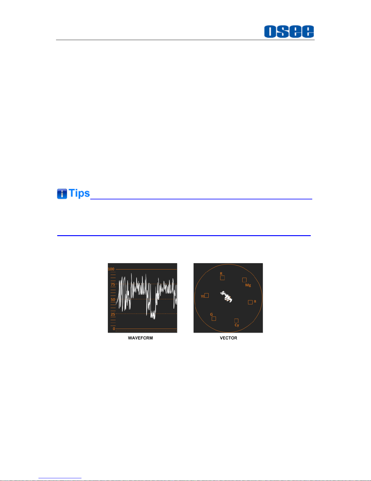
WAVE FORM & VECTOR
Figure 4.1-17 WAVEFORM and VECTOR
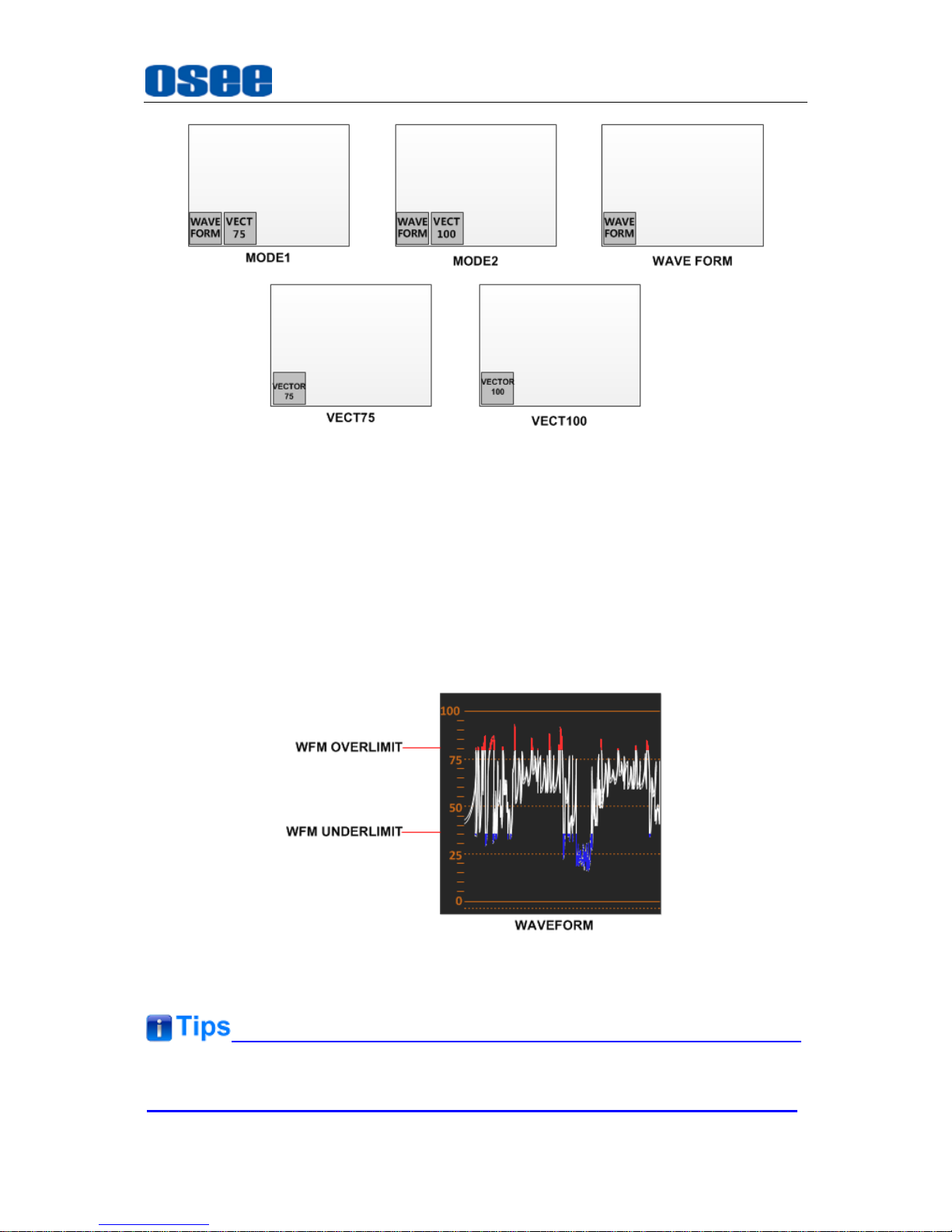
Set DISPLAYWFM FORM TYPE item to be MODE1(WAVE FORM& VECT75),
MODE2(WAVE FORM&VECT100), VECT100, VECT75, or WAVE FORM, the
waveform window or the vector window will be displayed at the desired position on
the image.
Page 45
Menu Operations
39
Figure 4.1-18 WAVE FORM TYPE
The WFM POSITION item is used to set the position of the wave form/vector display,
and you can select from left bottom or right bottom.
The WFM TRANS item is used to set the transparent of the wave form window and
the vector window.
Use the WFM OVERLIMIT item and the WFM UNDERLIMIT item to set the threshold
for the wave form, and the waveform overstepping WFM OVERLIMIT or WFM
UNDERLIMIT will be painted with distinctive color. The ordinary part is in white, and
the higher part will be in red, and the lower part will be in blue.
Figure 4.1-19 WAVEFORM WITH OVERLIMIT and WFM UNDERLIMIT
The waveform or vector is not available in PBP and NATIVE mode.
Page 46
Menu Operations
40
TIME CODE
The DISPLAYTIME CODE setting is used to display a time code and set a desired
format for time code, only available for SDI input.
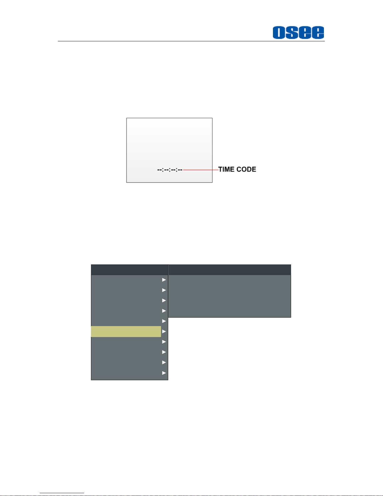
The time code is displayed at the bottom center of the screen. The mode could be
D-VITC, LTC or VITC, and the format is HH:MM:SS:FF. If there is no time code
available, the monitor will display "--:--:--:--".
Figure 4.1-20 TIME CODE
4.1.6 CLOSED CAPTION Menu
The CLOSED CAPTION menu items are used to set whether to display the closed
caption on screen, select the display mode and display standard, the menu items are
as shown in Figure 4.1-21:
SDI CC LOG
CLOSED CAPTION
CLOSE CAPTION
OFF
OFF
SDI CC TYPE
608 CHANNEL SEL
AUTO1
CC1
INPUT SELECT
MARKER
AUDIO
DISPLAY
CONFIG
LOOK PROFILE
FUNCTION KEY
STATUS
KEY INHIBIT
MAIN
CLOSED CAPTION
Figure 4.1-21 CLOSED CAPTION Menu
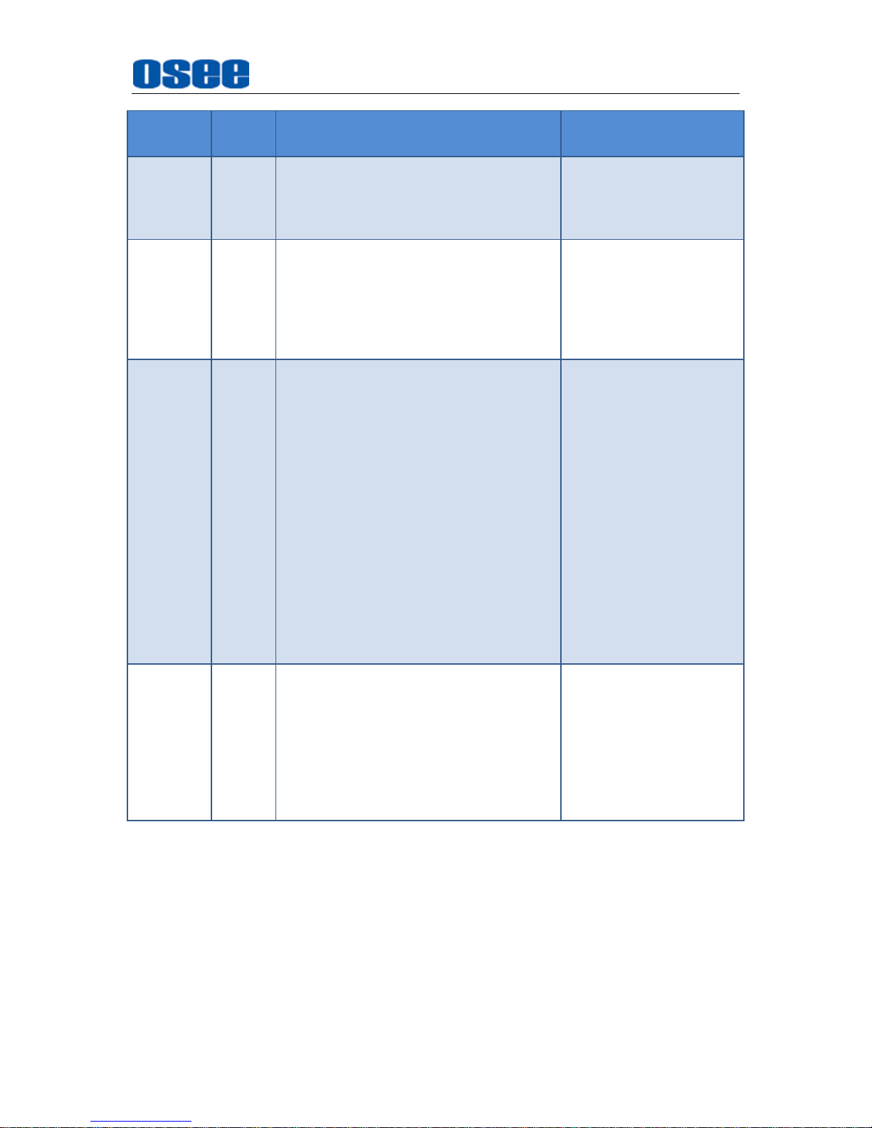
The relationship of Items, Default Value, Domain Range and Description of the
sub-item is as shown in Table 4.1-6:
Table 4.1-6 The Description of CLOSED CAPTION Menu Items
Page 47
Menu Operations
41
Items
Default
Value
Domain Range
Description
SDI CC
LOG
OFF
OFF/ON
Set whether to display
the SDI CC logo when
detecting closed caption
in SDI input signal.
CLOSED
CAPTION
OFF
OFF/ON
Set whether to display
the closed caption
information. Only
available when the
SUB
IN TYPE
item is set to
be OFF.
SDI CC
TYPE
AUTO1
AUTO1: set to 608(VBI) for
SD-SDI input and set to 608(708)
for HD-SDI input.
AUTO2: set to 608(ANC) for
SD-SDI input and set to 608(708)
for HD-SDI input.
608(708): display the 608 closed
caption signal transmitted by
EIA/CEA-708 standards.
608(ANC): display the ANC closed
caption signal transmitted by
EIA/CEA-608 or EIA/CEA-708
standards.
608(VBI): display the closed
caption signal of the EIA/CEA-608
standards in Line 21.
Set the closed caption
type, and select
608(VBI) item when the
input is CVBS.
608
CHANNEL
SEL
CC1
CC1
CC2
CC3
CC4
TEXT1
TEXT2
TEXT3
TEXT4
Select closed caption
transmission channel.
CLOSED CAPTION
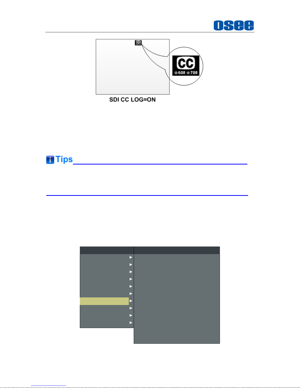
There will be a SDI CC logo displayed at the top center of the screen, which indicates
available CLOSED CAPTION (CC for short) information in the current SDI signal
source. Set CLOSED CAPTIONSDI CC LOG to be ON to enable this detection.
Page 48
Menu Operations
42
Figure 4.1-22 SDI CC LOGO
Set CLOSED CAPTION CLOSED CAPTION to be ON to display the closed
caption transmitted in the signal source, then, select a transmission standard
accordant with the signal input among AUTO1(608(VBI)& 608(708)),
AUTO2(608(ANC)& 608(708)), 608(708), 608(ANC), 608(VBI).
You should set
CONFIGSUB IN TYPE
to be
OFF
to close the multiple images
display mode, thus to display the closed caption in single image display mode.
4.1.7 CONFIG Menu
The CONFIG menu items are used to set Fast mode, multiple images display mode
and settings, backlight, auto standby mode, aperture, language mode, horizontal flip,
and uniformity, the menu items are as shown in Figure 4.1-23:
AUDIO
FUNCTION KEY
MAIN
CONFIG
LOOK PROFILE
CLOSED CAPTION
DISPLAY
MARKER
INPUT SELECT
STATUS
KEY INHIBIT
PIP POSITION
FAST MODE
FILM MODE DETECT
SUB IN TYPE
SUB IN SELECT
PIP SIZE
CONFIG
HORIZONTAL
OFF
OFF
PBP
SDI1
LARGE
AUTO STANDBY
APERTURE
OFF
0
H FLIP OFF
UNIFORMITY ON
LANGUAGE ENGLISH
BACKLIGHT 30
Figure 4.1-23 CONFIG Menu
Page 49
Menu Operations
43
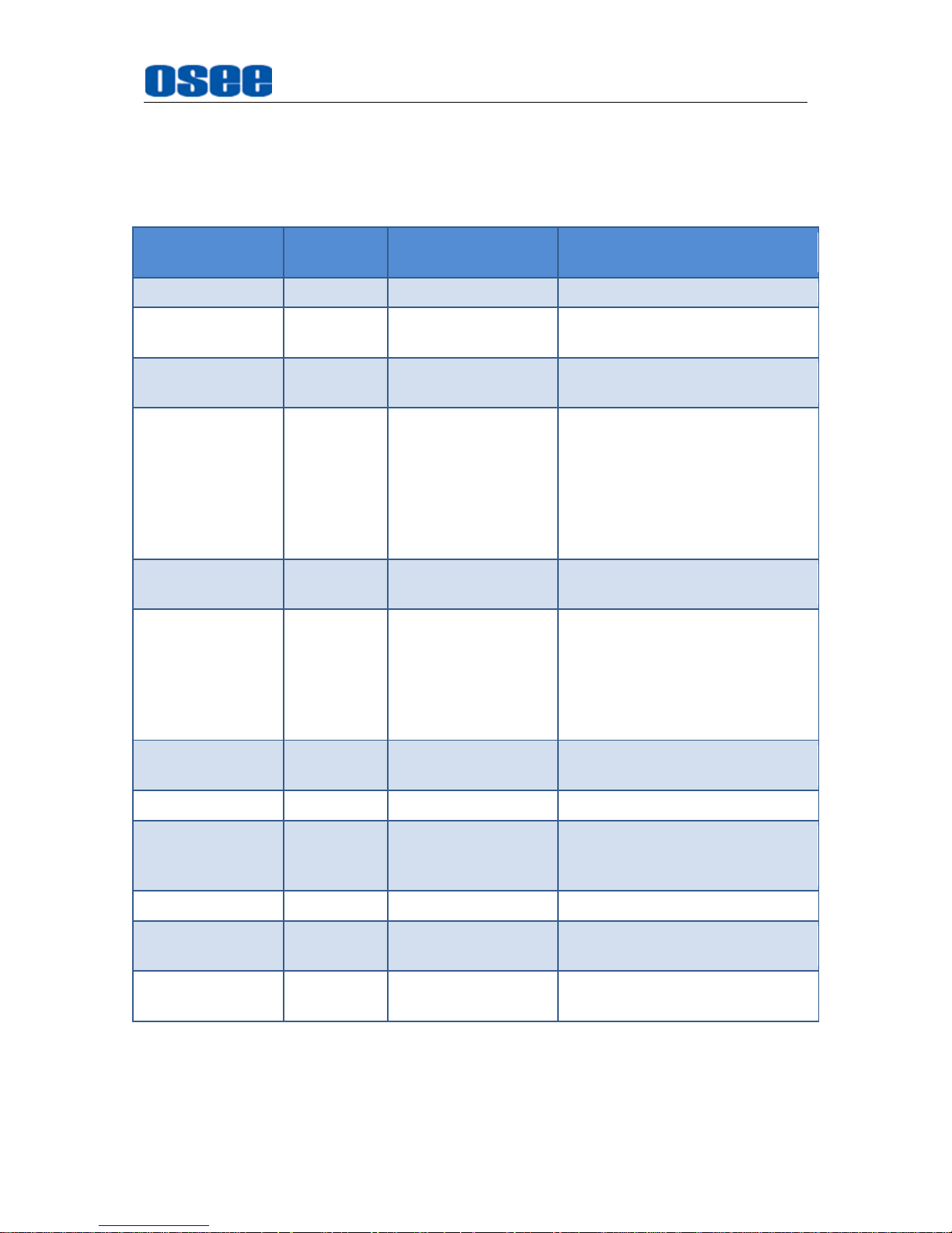
The relationship of Items, Default Value, Domain Range and Description of the
sub-item is as shown in Table 4.1-7:
Table 4.1-7 The Description of CONFIG Menu Items
Items
Default
Value
Domain Range
Description
FAST MODE
OFF
OFF/ON
Enable/Disable the fast mode.
FILM MODE
DETECT
OFF
OFF/ON
Set whether to detect 24PsF
mode.
SUB IN TYPE
OFF
PBP/PIP/OFF
Set the display mode of screen
picture.
SUB IN SELECT
SDI2
SDI1
SDI2
LINE1(CVBS)
LINE2(CVBS)
LINE2(Y/C)
LINE2(YPBPR)
HDMI
Set the signal input for the slave
image, refer to Table 4.1-9 for
the details.
PIP SIZE
SMALL
SMALL/LARGE
Set the size of the slave picture
in PIP mode.
PIP POSITION
BOT RIGHT
BOT LEFT:
bottom left
BOT RIGHT:
bottom right
TOP RIGHT
TOP LEFT
Set the position of the slave
image in PIP mode.
BACK LIGHT
30
0~30
Set the backlight level of the
LCD panel.
AUTO STANDBY
OFF
OFF/ON
Enable/Disable standby mode.
APERTURE
0
0~24
Set the sharpness level of the
image. The higher the value, the
sharpener the image.
LANGUAGE
ENGLISH
ENGLISH/CHINESE
Select a language mode
H FLIP
OFF
OFF/ON
Set whether to inverse the
image horizontally displayed.
UNIFORMITY
ON
OFF/ON
Enable/Disable the uniformity
function.
FAST MODE
When displaying interlaced input signal, FAST mode is used to reduce the 3D
de-interlacing processing time delay, set CONFIGFAST MODE to be ON to enable
Page 50
Menu Operations
44
the FAST mode. The fast mode feature has the appearance progressive input signal.
While FAST mode is set as OFF, the monitor will adopt a 3D de-interlacing
processing which will deal a frame of interlaced signal to be 2 full fields (an odd field
and an even field), this will improve the quality of video with fine details and reduce
the signal dithering.
The fast mode is only effective for interlaced signals.
PIP PBP(Display Multiple Images)
To display two input signals simultaneously on the monitor’s screen, you could set the
CONFIGSUB IN TYPE item to be PIP or PBP.
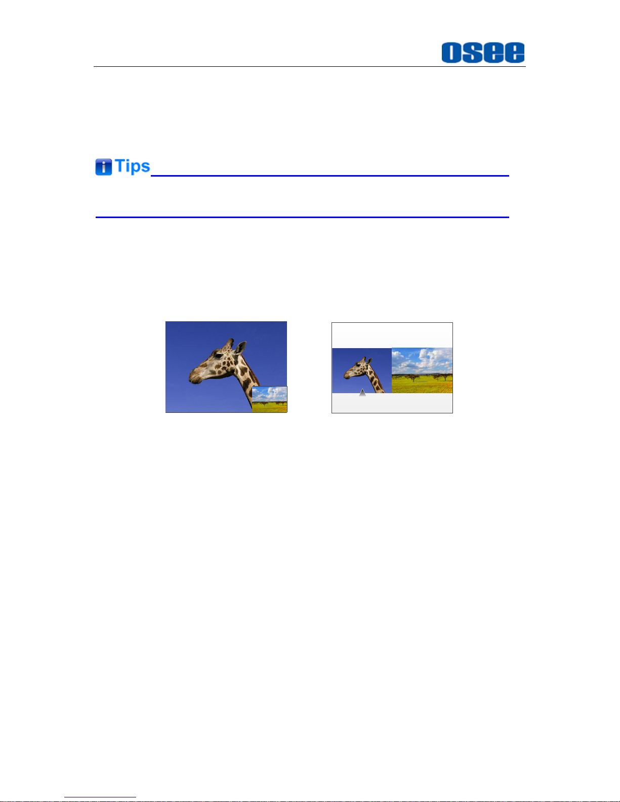
This monitor provides two modes for picture & picture display: PIP, PBP, and the
relevant relationship of the two pictures are as shown in Figure 4.1-24:
INPUT1 INPUT2
INPUT1
INPUT2
PIP PBP
Figure 4.1-24 Multiple Inputs
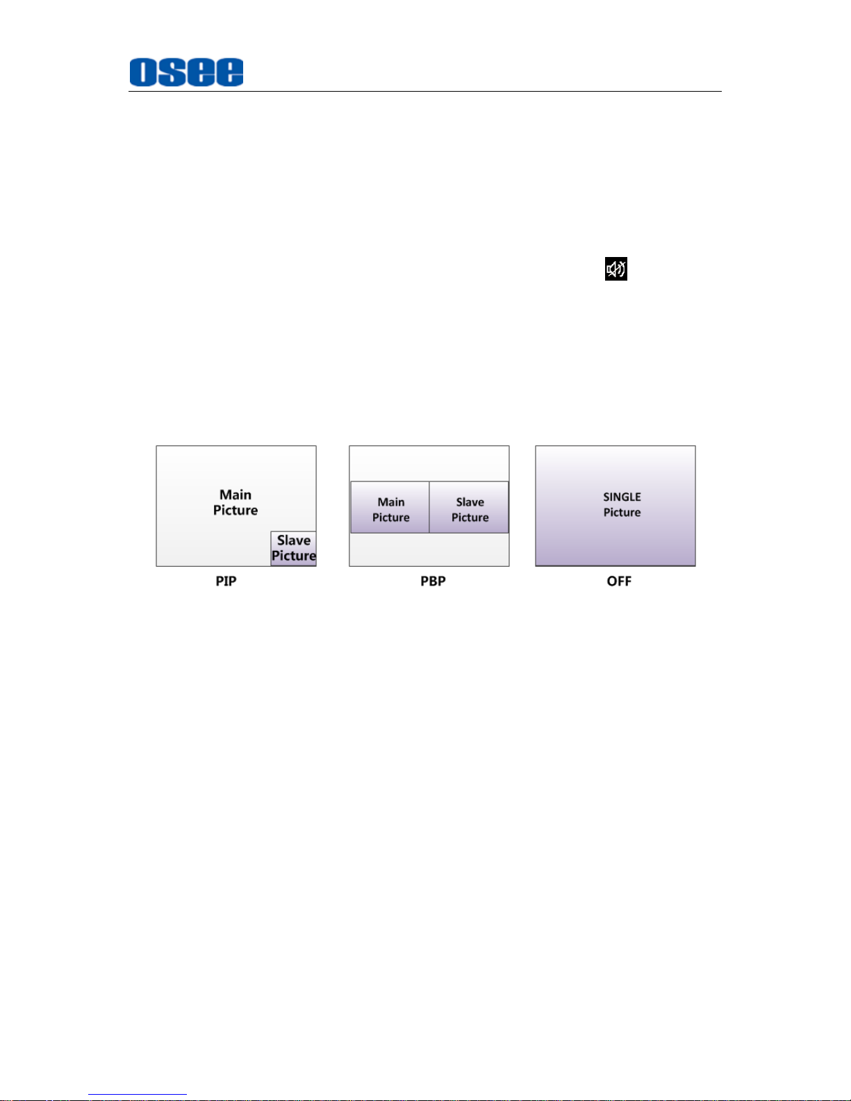
PIP (Picture in Picture)
The two pictures generated by two input signals separately are displayed one in
another. One is displayed on full screen, called as the main picture, and the other is
displayed in an inset window, called as the slave picture. In PIP mode, the relevant
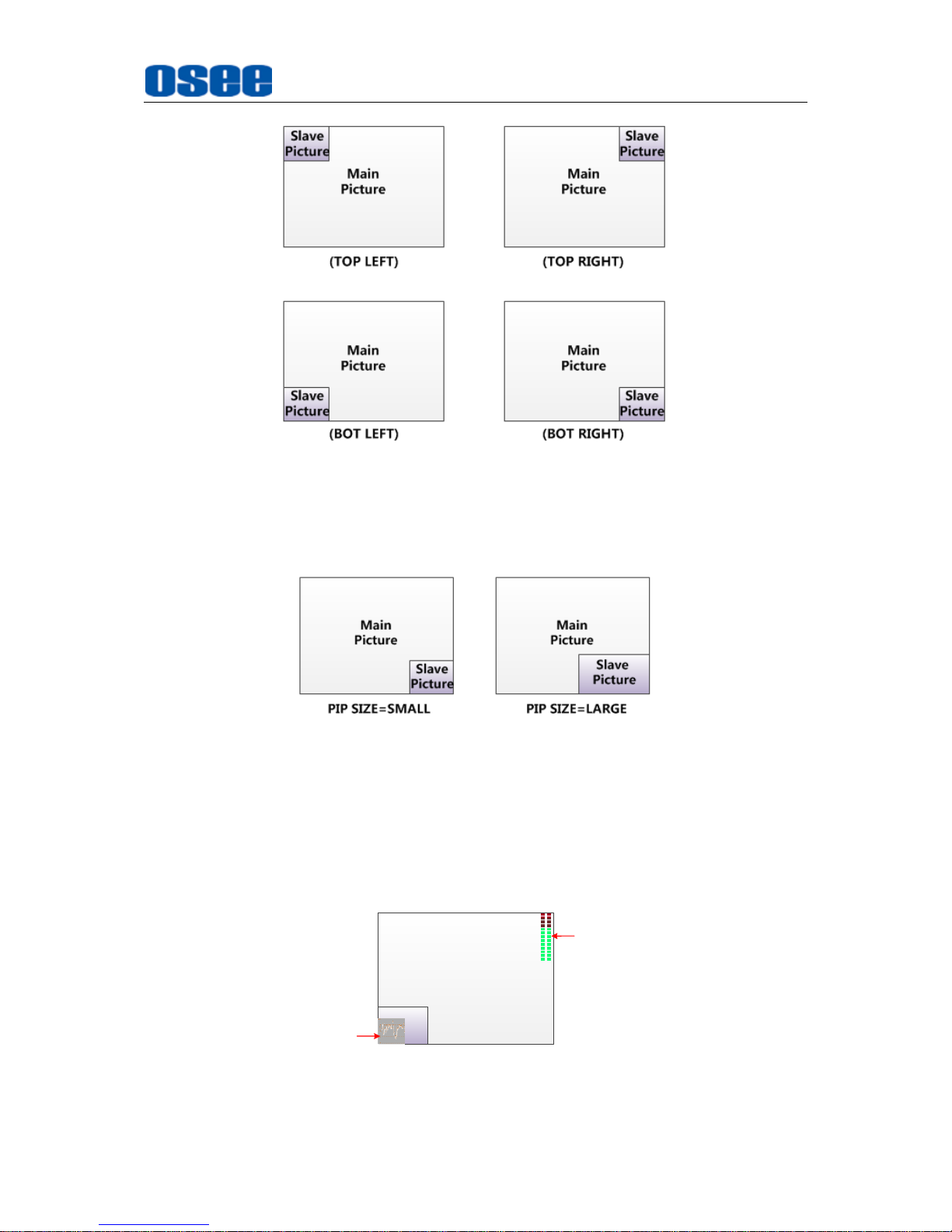
position relationship of the main picture and the slave picture is set by CONFIGPIP
POSITION item, as shown in Figure 4.1-25:
Page 51
Menu Operations
45
Figure 4.1-25 The Position Relationship in PIP Mode
Adjust the display size by CONFIGPIP SIZE item, and there are two kinds of
outlines for the slave picture, as shown in Figure 4.1-26:
Figure 4.1-26 The Size for the Slave Picture
In PIP mode, it displays the waveform/vector or Audio Meter only for the signal source
of the main picture. If the waveform/vector window is displayed, the Audio Meter will
be display only at the top position (Top left or Top right) at the screen.
For example, the WFM displays at the bottom left, and the Audio Meter could be only
displayed at the top position in case of collision, as shown in Figure 4.1-27:
Main
Picture
Slave
Picture
(BOT LEFT)
Audio Meter
WFM
Figure 4.1-27 The Illustrate for WFM and Audio Meter Display
Page 52
Menu Operations
46
PBP(Picture by Picture)
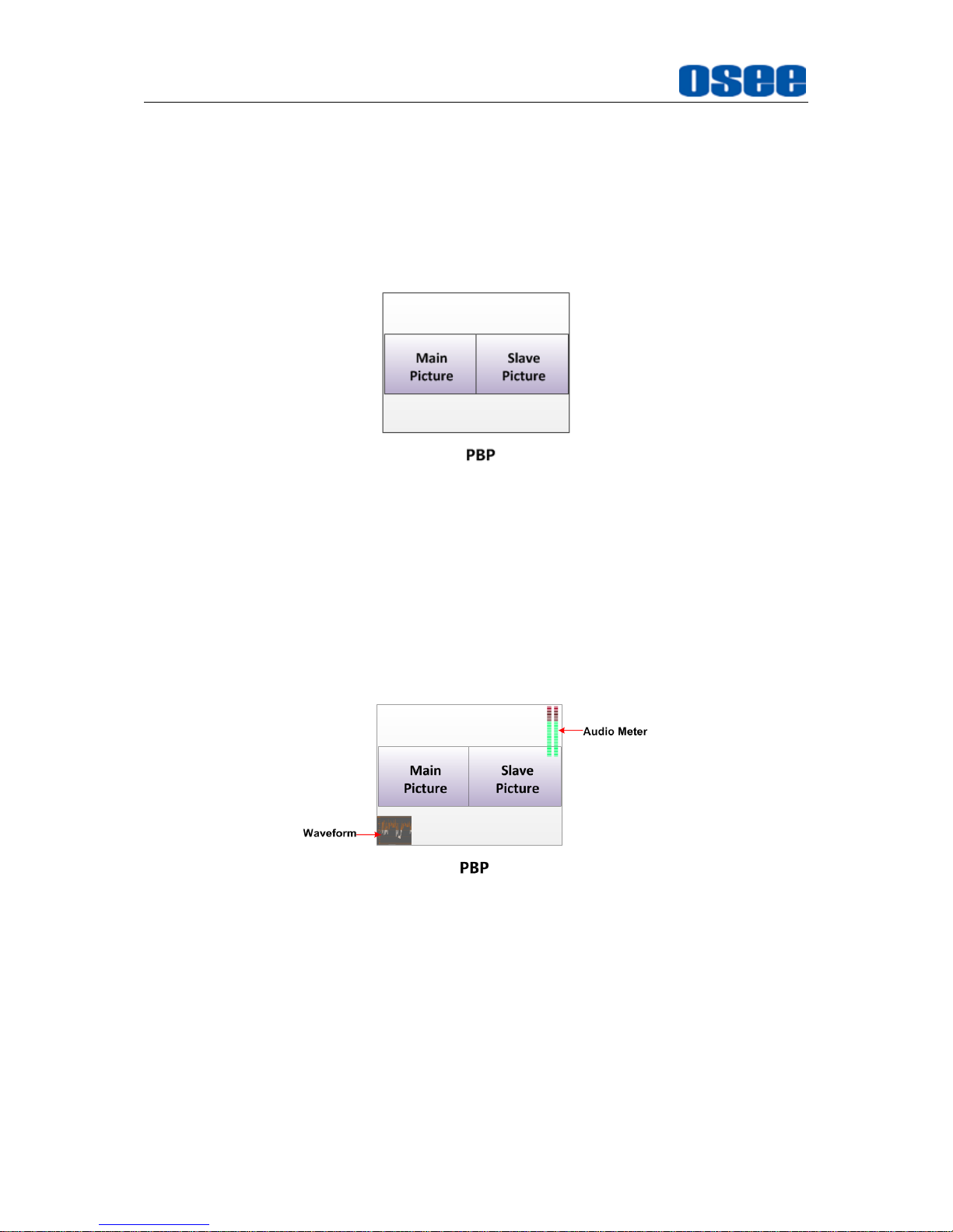
The two pictures generated by two input signals separately are displayed side by side,
and this function helps with white balance adjustment, and determining shooting
angles between two cameras etc.
In PBP mode, the size of the main picture is as large as the slave picture’s. The
picture displayed at the left side is called as Main picture, and the left is called as
Slave picture, as shown Figure 4.1-28:
Figure 4.1-28 PBP Mode
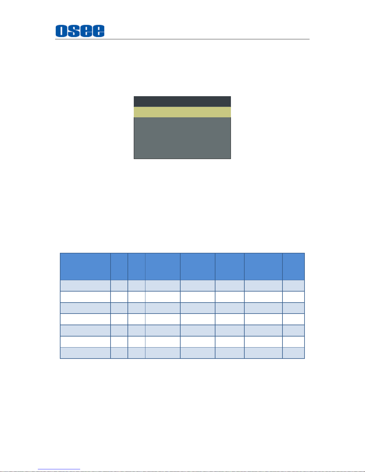
In PBP mode, it displays the waveform/vector window for the whole screen, including
the main signal and the slave signal, but for Audio Meter, it is only for the signal of the
main picture, as shown in Figure 4.1-29.
In case of position collision, the waveform/vector window could only be displayed at
the left bottom or right bottom of the screen, as shown in Figure 4.1-29, and
meantime, the Audio Meter could be display only at the top position (Top left or Top
right) at the screen in case of collision.
Figure 4.1-29 Position of WFM and Audio Meter in PBP Mode
Set Display Mode
The display mode on the screen could be single(SUB IN TYPE is OFF), PBP, PIP, set
as instructed below:
OPERATION
Method 1
: Set By menu item
Select the
Config SUB IN TYPE
item, use
ENTER, UP
or
DOWN
key to select
a display mode among
OFF, PBP
and
PIP
.
Page 53
Menu Operations
47
Method 2
: Set By function key
Designate
PBP
function to a function key, then press this function key to switch it
value among
OFF, PBP
and
PIP
.
For example,
Select the
FUNCTION KEY F1
item, and set its value as
PBP
,
as shown in
Figure 4.1-30
, then, press F1 to switch the display mode.
F1 PBPPBP
F2 OFFNATIVE
FUNCTION
F3 4:3ANAMORPHIC
F4 OFFFLASE COLOR
F5 OFFFREEZE
Figure 4.1-30 Set the Function Key as PBP
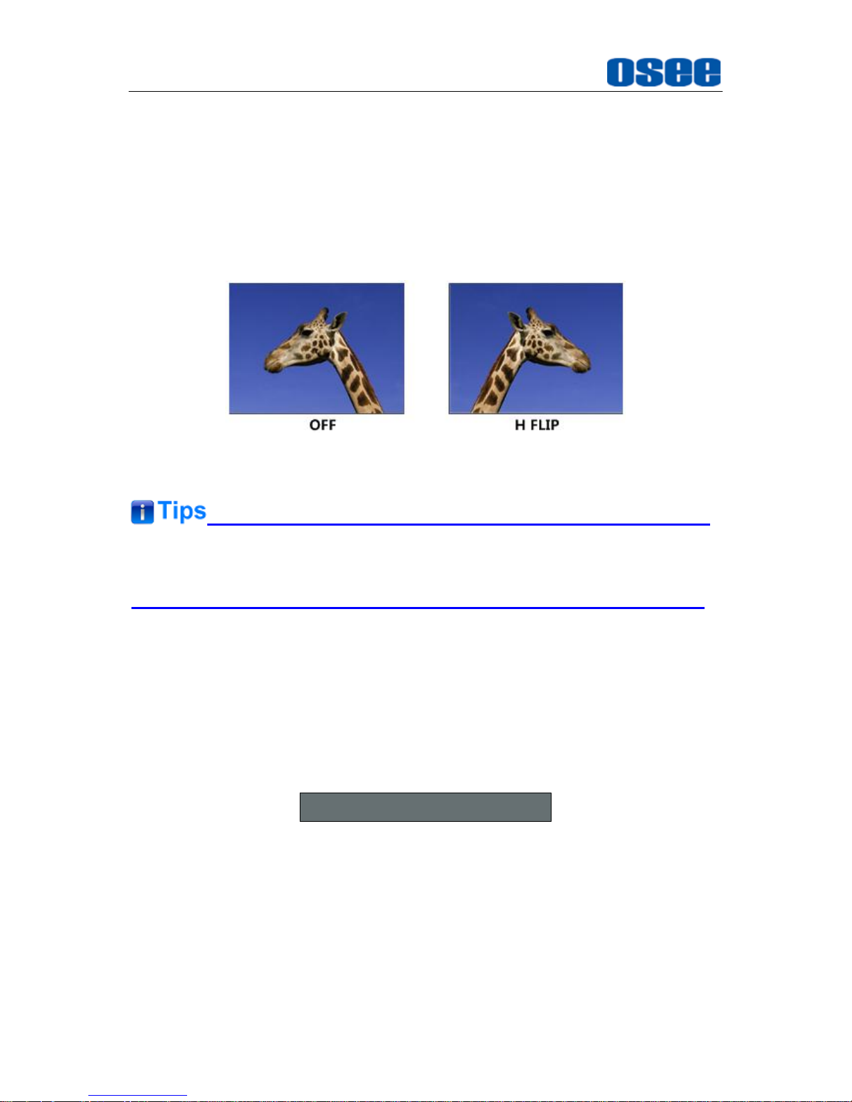
Scope for the signal source of the slave picture
The selection scope of the signal source for the slave picture will be changing in
accordance with the main picture's source, the available formats are as shown in
Table 4.1-9:
Table 4.1-8 The Relationship of the Signal Source for Slave Picture and Main
Picture
Signal Source for
Main Picture
\ Signal Source for
Slave Picture
SDI1
SDI2
LINE1(CVBS)
LINE2(CVBS)
LINE2(Y/C)
LINE2(YPSPR)
HDMI
SDI1
SDI2
LINE1(CVBS)
LINE2(CVBS)
LINE2(Y/C)
LINE2(YPBPR)
HDMI
Position for signal source menu
: The input signal information of the main
picture displays at the top left corner of the screen, and the one of the slave
picture displays at the top right corner of the screen.
Settings for signal source
: Press
INPUT
button to set the signal source for
the main picture, and select
CONFIGSUB IN TYPE
item to set the signal
source for the slave picture.
Page 54
Menu Operations
48
H FLIP MODE
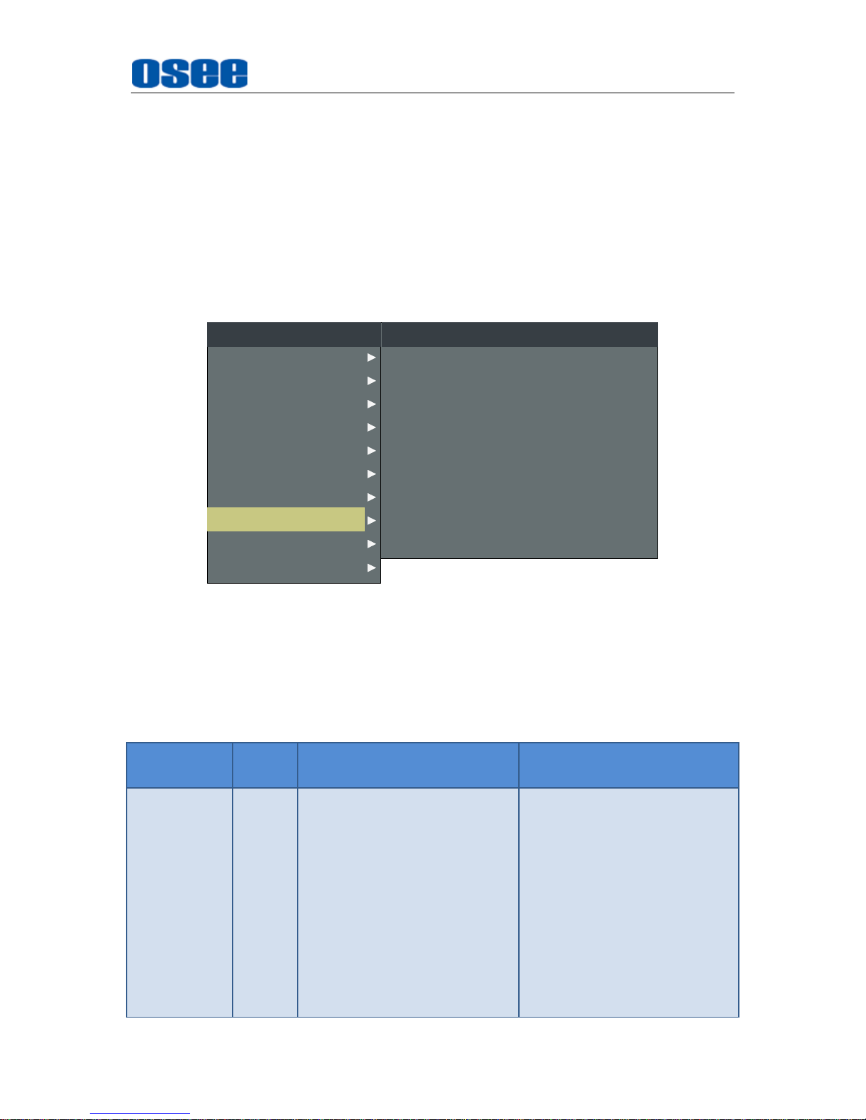
The input signal has been inverted horizontally by a mirror type in H FLIP Display
mode.
Select the menu item CONFIG H FLIP to be set to ON, or enable H FLIP in its
coalesced Function Key in Function Key menu, thus to inverse the images
horizontally.
The display result in the Horizontal FLIP MODE is as shown in Figure 4.1-31:
Figure 4.1-31 Horizontal Flip Mode
H FLIP
mode does not effect on Waveform/Vector, that is, the Wave Form of the
input signal in
H FLIP
mode will not be inversed horizontally.
AUTO STANDBY
The Auto Standby mode is used to set the status of the monitor when the Power
button is turned on or off.
ON
: set
AUTO STANDBY
item as ON to enable the auto standby mode. Thus,
when detecting no signal input or signal disappeared, the auto standby will be
activated, and there will be a prompt during the process, as shown in
Figure
4.1-32
:
Going into Standby Mode
Figure 4.1-32 Entering the Auto Standby Mode
When detecting no signal input or signal disappeared, the power indicator will
be lit in flash green for 10 seconds, and showing the standby prompt, after that,
the monitor screen will be turned off, and it will be in auto standby mode, the
POWER indicator is lit in red. Then, if the signal input is restored, the monitor
screen will recover and lit up automatically.
Page 55
Menu Operations
49
OFF
: set
AUTO STANDBY
as
OFF
to disable the auto standby mode.
Press
POWER
button when the monitor is in operation mode, it will power off the
monitor, otherwise, press
POWER
button when the monitor is off, thus it will
power on the monitor, and the
POWER
indicator is lit in green.
4.1.8 LOOK PROFILE Menu
The LOOK PROFILE menu provides versatile color spaces, the items are used to
switch to distinctive LOOK PROFILE feature and adjust color balance parameters, as
shown in Figure 4.1-33:
GREEN BIAS
LOOK PROFILE
RED GAIN
GREEN GAIN
BLUE GAIN
RED BIAS
BLUE BIAS
0
D65 Rec709
128
128
128
0
0
LOOK PROFILE
RESET
USER LUT NAME XXXXXXXXXXXX
CLOSED CAPTION
INPUT SELECT
MARKER
AUDIO
DISPLAY
CONFIG
FUNCTION KEY
MAIN
STATUS
KEY INHIBIT
LOOK PROFILE
Figure 4.1-33 LOOK PROFILE Menu
The relationship of Items, Default Value, Domain Range and Description of the
sub-item is as shown in Table 4.1-9:
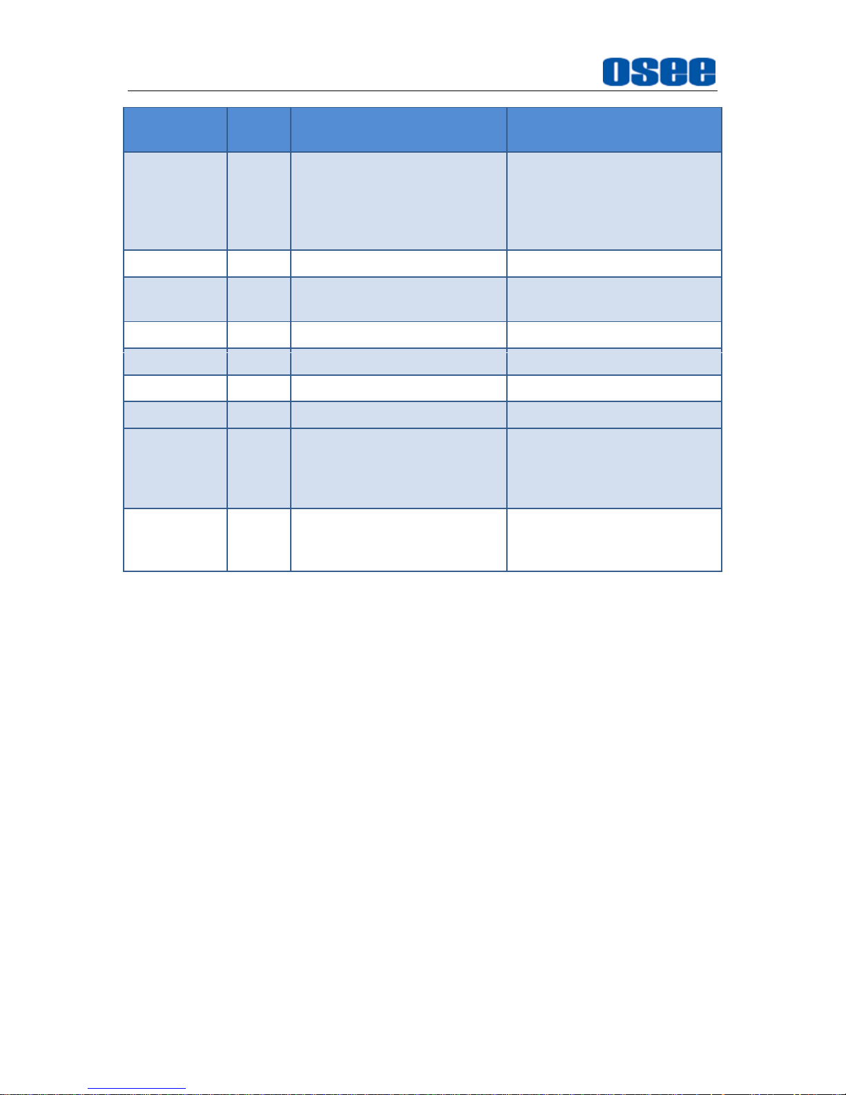
Table 4.1-9 The Description of LOOK PROFILE Menu Items
Items
Default
Value
Domain Range
Description
LOOK
PROFILE
D65
D65 Rec709
DCI P3
Rec BT.2020
ARRI_LOG_R709
BMD_CC_FILM_V
BMD_PC_FILM_V2
Canon_CinCL1_WDR
Canon_CinCL2_WDR
Pana_VLog_V709
RED_RLF_RG3
SONY_SL2_LC709A
SONY_SL3C_L709A
Select a color look profile as
your desired color space.
Page 56
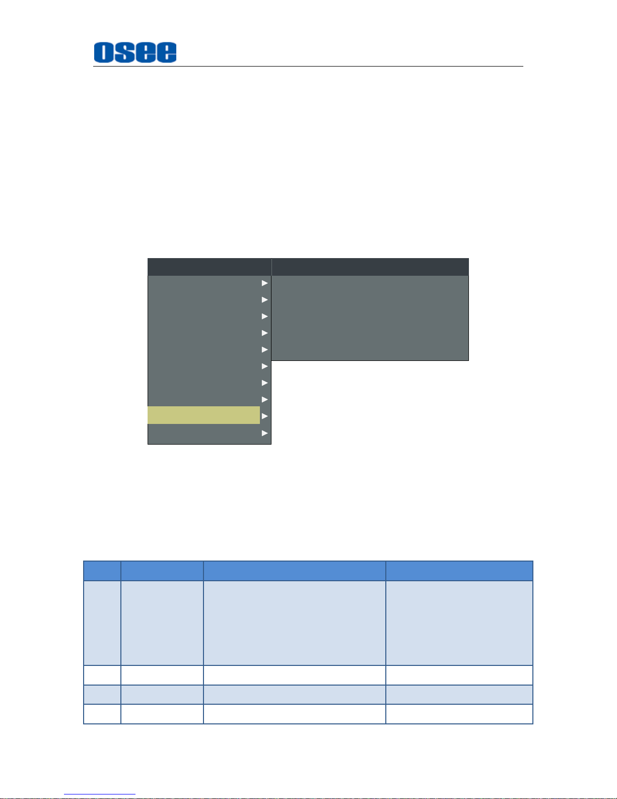
Menu Operations
50
Items
Default
Value
Domain Range
Description
Panavision_R709
USER1
USER2
USER3
USER4
RED GAIN
128
0~128
Adjust the Red Gain
GREEN
GAIN
128
0~128
Adjust the Green Gain
BLUE GAIN
128
0~128
Adjust the Blue Gain
RED BIAS
0
-127~127
Adjust the Red Offset
GREEN BIAS
0
-127~127
Adjust the Green Offset
BLUE BIAS
0
-127~127
Adjust the Blue Offset
RESET
--
--
Reset the Gain and Offset
values to default values for
the current profile set by
LOOK PROFILE
item.
USER LUT
NAME
--
--
Display the user LUT name in
this value area, it supports up
to 16 characters.
LOOK PROFILE
The monitor is equipped with versatile color lookup profiles for several different color
spaces. We provide 17 sheets of color profiles as follows:
Standard LUTs
: D65 Rec709, DCI P3, Rec BT.2020;
10 camera log to REC 709 LUT
: ARRI_LOG_R709, BMD_CC_FILM_V,
BMD_PC_FILM_V2, Canon_CinCL1_WDR, Canon_CinCL2_WDR,
Pana_VLog_V709, RED_RLF_RG3, SONY_SL2_LC709A,
SONY_SL3C_L709A, Panavision_R709;
4 user LUTs
: USER1, USER2, USER3, USER4.
Each profile has a group of RED/GREEN/BLUE GAIN and BIAS settings, and the
value of RED/GREEN/BLUE GAIN and BIAS are all adjustable for your current LUT
designated in LOOK PROFILE LOOK PROFILE item.
User Luts
LCM156-E monitor is capable of loading customized calibration 3D LUTs to USER1,
USER2, USER3 or USER4 in the LOOK PROFILE list. This advanced feature
requires use of color management software (we support SpectralCal’s CalMAN
currently), which could generate the customized calibration 3D LUTs, and OSEE
Page 57
Menu Operations
51
Utility Tools (provided by OSEE) which could load the customized calibration 3D LUTs
to specified monitor.
LOOK PROFILE Reset
Set LOOK PROFILE RESET item, it will reset the Gain and Offset values to default
values for the current profile selected in the LOOK PROFILE item.
4.1.9 FUNCTION KEY Menu
The FUNCTION KEY menu items are used to assign function to the function buttons
(F1~F5) on the front panel, and turn the function on or off. The menu items of
FUNCTION KEY are as shown in Figure 4.1-34:
F1
F2
FUNCTION KEY
FOCUS ASSIST
NATIVE
F3
F4
ANAMORPHIC
FALSE COLOR
F5 PBP
CLOSED CAPTION
INPUT SELECT
MARKER
AUDIO
DISPLAY
CONFIG
LOOK PROFILE
MAIN
STATUS
KEY INHIBIT
FUNCTION KEY
Figure 4.1-34 FUNCTION KEY Menu
The relationship of Items, Default Value, Domain Range and Description of the
sub-item is as shown in Table 4.1-10:
Table 4.1-10 The Description of FUNCTION KEY Menu Items
Items
Default Value
Domain Range
Description
F1
FOCUS
ASSIST
NATIVE, ANAMORPHIC, BLUE
ONLY, MONO, MARKER, AUDIO
METER, FAST MODE, TC,
MUTE, PBP, CC, FREEZE,
FOCUS ASSIST, ZEBRA, H FLIP,
FALSE COLOR, UNDEF
Set a function to F1 button
F2
NATIVE
the same as F1
Set a function to F2 button
F3
ANAMORPHIC
the same as F1
Set a function to F3 button
F4
FALSE
the same as F1
Set a function to F4 button
Page 58
Menu Operations
52
Items
Default Value
Domain Range
Description
COLOR
F5
PBP
the same as F1
Set a function to F5 button
Assign Function Key
To assign a desired function to a function button(F1~F5).
For example, set FUNCTION KEYF1 item to be FALSE COLOR, then press F1
button on the front panel of the monitor, it will display the Function Menu at the left
bottom of the screen, and F1 line is highlighted, press F1 button again to change the
value for FALSE COLOR to be ON or OFF.
F1 ONFALSE COLOR
F2 OFFNATIVE
FUNCTION
F3 OFFMONO
F4 OFFFREEZE
F5 OFFPBP
NATIVE
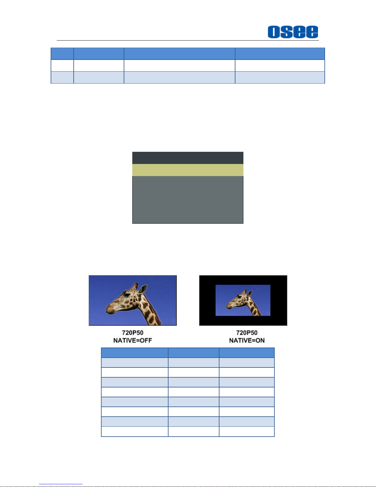
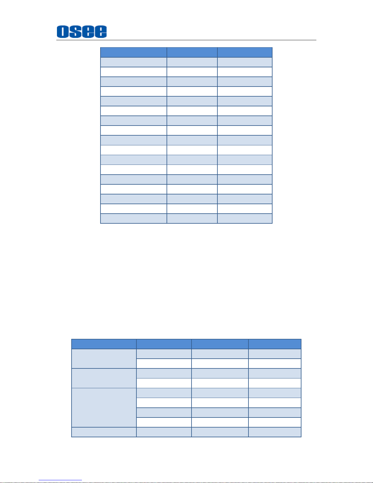
Press the button to activate the native scan mode, which provides a 1:1 pixel to pixel
mapped representation, thus to reproduce the images without changing the input
signal's pixel count.
INPUT SIGNAL
INPUT
OUTPUT
PAL
720X576
720X576
NTSC
720X483
720X483
720P24/23.98
1280X720
1280X720
720P25
1280X720
1280X720
720P30/29.97
1280X720
1280X720
720P50
1280X720
1280X720
720P60/59.94
1280X720
1280X720
1080SF24/23.98
1920X1080
1920X1080
Page 59
Menu Operations
53
INPUT SIGNAL
INPUT
OUTPUT
1035I60/59.94
1920X1035
1920X1080
1080I50
1920X1080
1920X1080
1080I60/59.94
1920X1080
1920X1080
1080P24/23.98
1920X1080
1920X1080
1080P25
1920X1080
1920X1080
1080P30/29.97
1920X1080
1920X1080
1080P50
1920X1080
1920X1080
1080P60/59.94
1920X1080
1920X1080
2048X1080PSF24/23.98
2048X1080
2048X1080
2048X1080PSF25
2048X1080
2048X1080
2048X1080PSF30/29.97
2048X1080
2048X1080
2048X1080P24/23.98
2048X1080
2048X1080
2048X1080P25
2048X1080
2048X1080
2048X1080P30/29.97
2048X1080
2048X1080
2048X1080P48/47.94
2048X1080
2048X1080
2048X1080P50
2048X1080
2048X1080
2048X1080P60/59.94
2048X1080
2048X1080
ANAMORPHIC
Press the button to activate the anamorphic mode. For HD-SDI, 3G-SDI and 2K
signals, you could set the de-squeeze modes to be OFF(16:9), X1.3, X2, X2 MAG.
For SD-SDI signals, set the aspect ratio to be 4:3 or OFF(16:9).
This feature enables you to de-squeeze HD-SDI, 3G-SDI and 2K signals coming from
camera utilizing anamorphic lenses that may not have a built-in de-squeeze feature of
their own. This is quite useful in applications, such as outdoor post production, onset
monitoring, real-time de-squeezing, etc.
The resolution of the input and output are as shown in Table 4.1-11:
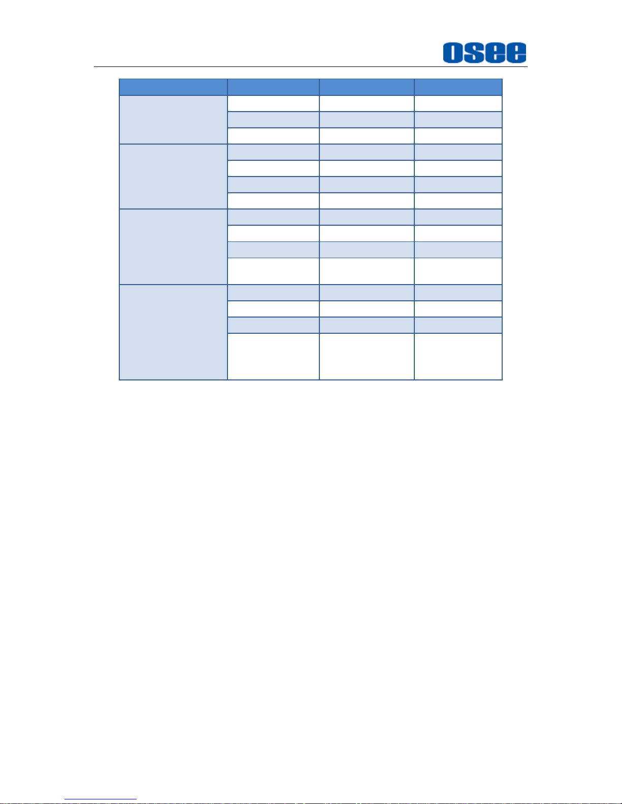
Table 4.1-11 Resolution Relationship Between Input and Output
INPUT SIGNAL
ANAMORPHIC
INPUT
OUTPUT
PAL
4:3
720X576
1440X1080
16:9
720X576
1920X1080
NTSC
4:3
720X483
1440X1080
16:9
720X483
1920X1080
720P24/23.98
720P25
720P30/29.97
720P50
720P60/59.94
OFF
1280X720
1920X1080
X1.3
1280X720
1920x812
X2
1280X720
1920x540
X2 MAG
860X720
1920x804
1080SF24/23.98
OFF
1920X1080
1920X1080
Page 60
Menu Operations
54
INPUT SIGNAL
ANAMORPHIC
INPUT
OUTPUT
X1.3
1920X1080
1920X812
X2
1920X1080
1920X540
X2 MAG
1290X1080
1920X804
1035I60/59.94
OFF
1920X1035
1920X1080
X1.3
1920X1035
1920X812
X2
1920X1035
1920X540
X2 MAG
1290X1035
1920X804
1080I50
1080I60/59.94
1080P24/23.98
1080P25
1080P30/29.97
1080P50
1080P60/59.94
OFF
1920X1080
1920X1080
X1.3
1920X1080
1920X812
X2
1920X1080
1920X540
X2 MAG
1290X1080
1920X804
2048X1080PSF24/23.98
2048X1080PSF25
2048X1080PSF30/29.97
2048X1080P24/23.98
2048X1080P25
2048X1080P30/29.97
2048X1080P48/47.94
2048X1080P50
2048X1080P60/59.94
OFF
2048X1080
1920X1080
X1.3
2048X1080
1920X762
X2
2048X1080
1920X506
X2 MAG
1290X1080
1920X804
BLUE ONLY
Press the button to activate BLUE ONLY mode that will remove red and green from
the input signal, and only blue signal is displayed as a monochrome image on the
screen.
MONO
Press the button to activate MONO mode that will display the image in monochrome
presentation, inactivate this mode to display the screen in color mode.
MARKER
Press the button to activate the marker, including AREA MARKER, CENTER
MARKER and SAFETY MARKER. Set the marker in MARKER menu, and refer to
"4.1.3 MARKER Menu" for details.
AUDIO METER
Press the button to activate the audiometer. Set the audio meter in AUDIO menu, and
refer to "4.1.4 AUDIO Menu" for details.
FAST MODE
Press the button to activate FAST mode which will reduce the 3D de-interlacing
processing time delay.
Page 61
Menu Operations
55
TC
Press the button to toggle the TIME CODE value among D-VITC, LTC, VITC and OFF.
The time code is displayed at the bottom center of the screen. Refer to "4.1.5
DISPLAY Menu" for details.
MUTE
Press the button to mute the sound, and there will be mute prompt displayed at
the bottom right position of the screen.
PBP
Press the button to toggle the display mode among PBP, PIP and OFF(single). In
PBP mode or PIP mode, you can display two input signals simultaneously on the
monitor’s screen. You can specify the relative position of the two input pictures, and
set the source for each picture, refer to "4.1.7 CONFIG Menu" for details.
CC
Press the button to activate CC(closed caption) display. Refer to “4.1.6 CLOSED
CAPTION Menu” for the details.
FREEZE
Activate this function to freeze the current frame displayed, press the function button
again to release the freeze and continue to display.
FOCUS ASSIST
Press the button to toggle the FOCUS ASSIST display mode among COLOR, GRAY
and OFF. The area whose current focus value is over the reference focus level will be
highlighted in a designated color set by INPUT SELECTFOCUS COLOR item.
Refer to “4.1.2 INPUT SELECT Menu” for the details.
ZEBRA
Press the button to activate the ZEBRA display. The image area whose luminance is
higher than the reference ZEBRA LEVEL will be filled with a zebra pattern. Refer to
“4.1.2 INPUT SELECT Menu” for the details.
Page 62
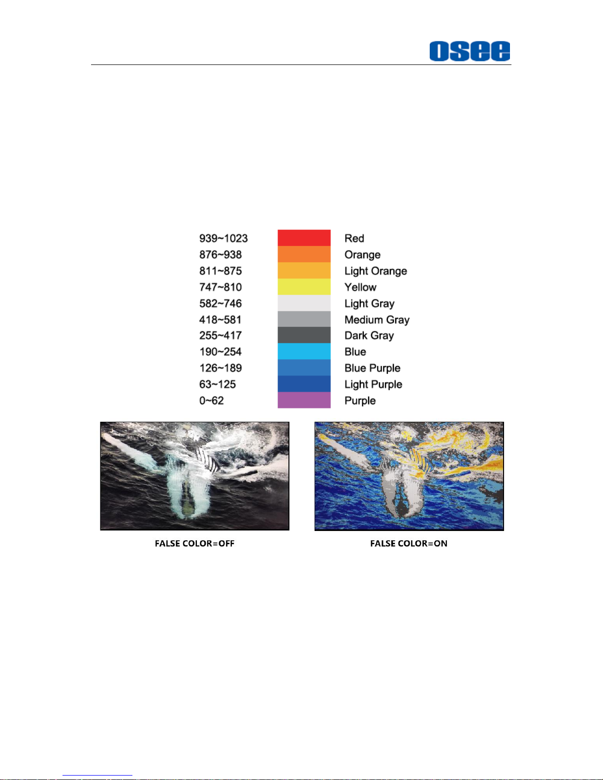
Menu Operations
56
H FLIP
Press the button to activate the horizontal flip display. The input signal will be inverted
horizontally by a mirror type.
FALSE COLOR
Press the button to activate the FALSE COLOR display of luminance values. This
function generates an artificial luminance map of the input source that can be useful
to identify over exposed areas. The following illustration indicates what artificial color
corresponds to what luminance level.
4.1.10 KEY INHIBIT Menu
The KEY INHIBIT menu item is used to lock the setting so that they can’t be changed
by an unauthorized user, and the menu item is as shown in Figure 4.1-35:
Page 63
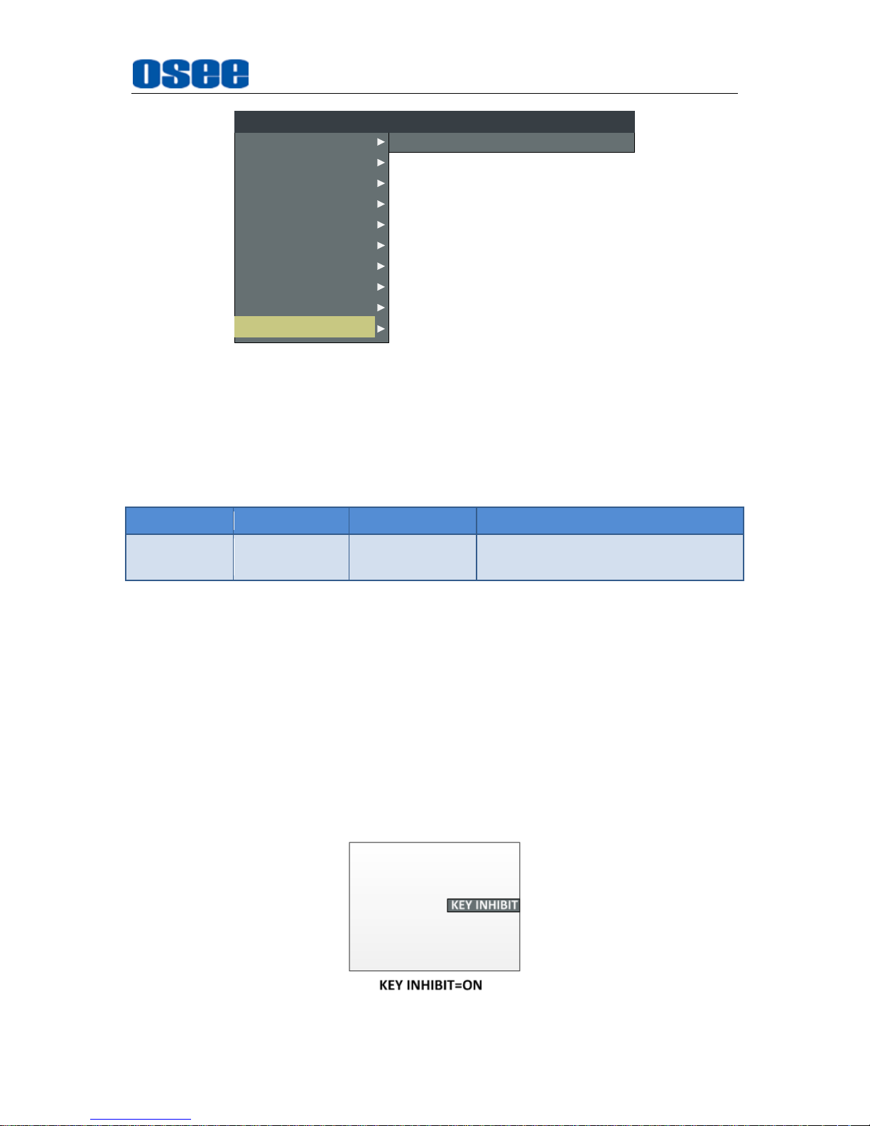
Menu Operations
57
KEY INHIBIT
KEY INHIBIT
OFF
CLOSED CAPTION
INPUT SELECT
MARKER
AUDIO
DISPLAY
CONFIG
LOOK PROFILE
FUNCTION KEY
MAIN
STATUS
KEY INHIBIT
Figure 4.1-35 KEY INHIBIT Menu
The relationship of Items, Default Value, Domain Range and Description of the
sub-item is as shown in Table 4.1-12:
Table 4.1-12 The Description of KEY INHIBIT Menu Items
Items
Default Value
Domain Range
Description
KEY INHIBIT
OFF
OFF/ON
Enable/Disable locking the setting
values.
Security--KEY INHIBIT
Set KEY INHIBITKEY INHIBIT to be ON to enable the key inhibition, thus you can
protect your setting values from being modified, and only POWER, MENU, UP,
DOWN, ENTER buttons are available.
After enabling the key inhibition function, you can only see the KEY INHIBIT menu in
On-screen menu. To disable the inhibition, use MENU, UP, DOWN, ENTER to
release this inhibition.
Meanwhile, you could press the POWER key to turn on or off the device.
In inhibition status, press anyone of F1~F5 buttons, it will display a "KEY INHIBIT”
prompt on right center of the screen, indicating the items are locked, as shown in
Figure 4.1-36.
Figure 4.1-36 KEY INHIBIT Prompt
Page 64
Menu Operations
58
4.2 Menu Settings
When checking or modifying the value of the menu item, cooperating with the
following buttons: MENU, UP, DOWN, ENTER. Take the following example to
descript usage of these buttons.
After you have loaded the Main Menu, it will be closed automatically if you do
nothing operation with it in 60s.
Selecting the Menu Language
You can select one of languages (English or Chinese) for displaying the menu. The
default language for the menu is ENGLISH. The following will teach you how to switch
to Chinese.
Operation:
Step 1 Select CONFIG menu
Press MENU button to display the OSD menu, click DOWN button to select
CONFIG menu.
Step 2 Select the value of the Language item
Press ENTER button to get into the CONFIG menu items, and click DOWN
button to select the sub-item LANGUAGE, then, click ENTER button to get
into the sub-value list, as shown in Figure 4.2-1, the current control icon is in
ENGLISH.
AUDIO
FUNCTION KEY
MAIN
CONFIG
LOOK PROFILE
CLOSED CAPTION
DISPLAY
MARKER
INPUT SELECT
STATUS
KEY INHIBIT
PIP POSITION
FAST MODE
FILM MODE DETECT
SUB IN TYPE
SUB IN SELECT
PIP SIZE
CONFIG
HORIZONTAL
OFF
OFF
PBP
SDI1
LARGE
AUTO STANDBY
APERTURE
OFF
0
H FLIP OFF
UNIFORMITY ON
LANGUAGE ENGLISH
BACKLIGHT 15
Figure 4.2-1 Select the Value of Language
Page 65
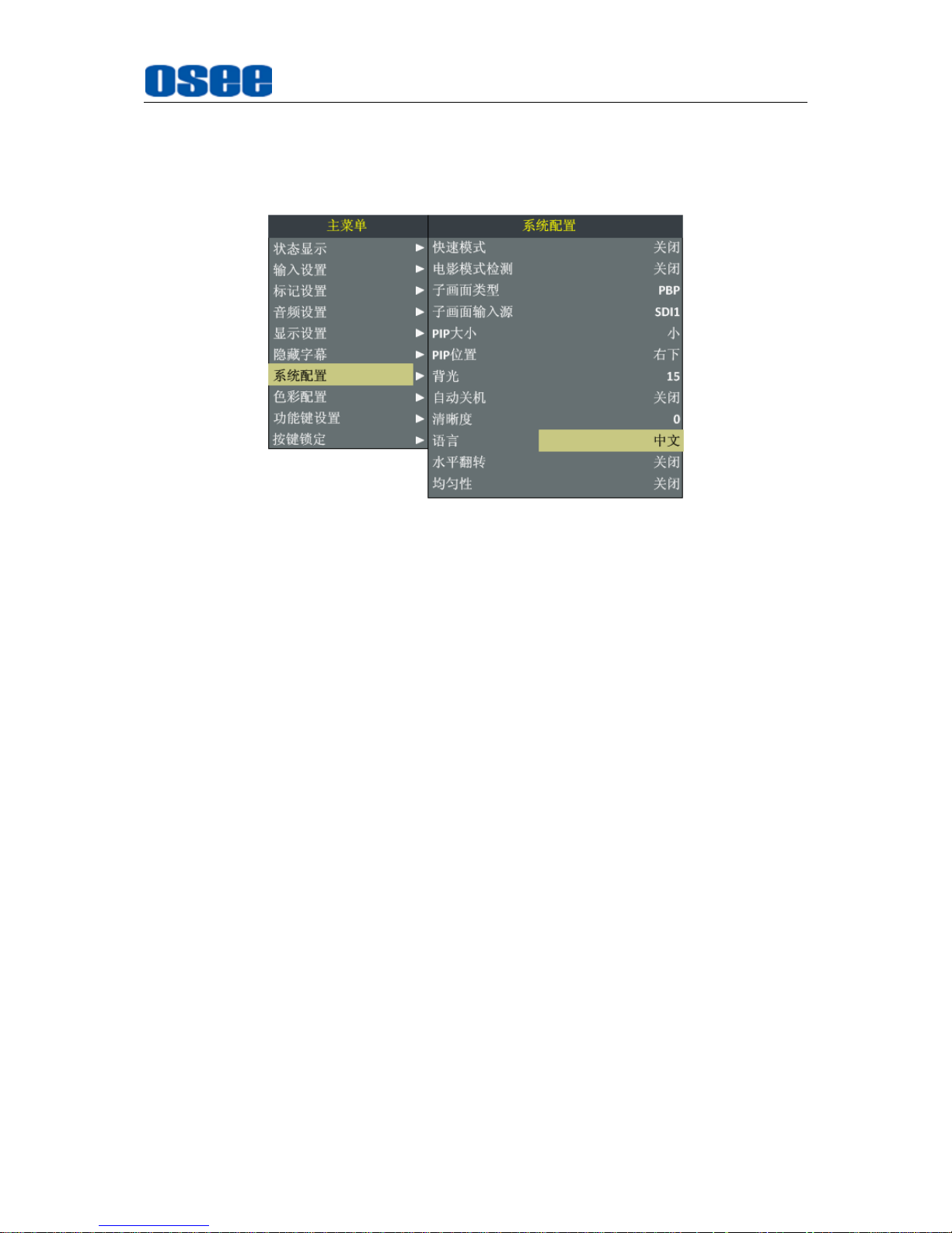
Menu Operations
59
Step 3 Confirm the modification of the value of sub-item
Click DOWN button to select the sub-item LANGUAGE to Chinese, as
shown in Figure 4.2-2, press ENTER button to confirm the modification.
Figure 4.2-2 Switching the Value of LANGUAGE
Step 4 Exit the Main Menu
Click MENU button to exit the Main Menu.
Page 66

60
Page 67
Specifications
61
Chapter 5 Specifications
5.1 Product detailed information
Specification
Values
Model
LCM156-E
LCM170-E
LCM230-E
Dimension
15.6”
17.3”
23”
Dimension(WxHxD)
380.7x240x70.5mm
421.8x264.3x73.5mm
556.5x340.5x75.5mm
Pixel Pitch (WxH)
0.179×0.179mm
0.199×0.199mm
0.2652×0.2652mm
Aspect Ratio
16:9
16:9
16:9
Display Area (WxH)
344.16×193.59mm
381.90×214.80mm
509.184×286.416mm
Viewing Angle (HxV)
178°x178°
178°x178°
178°x178°
Color Depth
1.073G colors
1.073G colors
16.7M colors(6bit + A-FRC)
Resolution
1920×1080
1920×1080
1920×1080
Contrast
700:1(Typ.)
600:1(Min)
1000:1(Typ.)
Luminance (cd/㎡)
300
300
250
Response Time (ms)
15
35
14
Backlight
RGB LED
RGB LED
White LED
Backlight Life(Hrs)
15000
15000
30000(Min)
Work Temperature
0°C~50°C
Power Supply
5A12V DC
Power Consumption
40W
30W
32W
Video Input Interface
CVBS(X2), S-Video, YPbPr,
HDMI(DVI-D), 3G/HD-SDI(X2)
HDMI(DVI-D), 3G/HD-SDI(X2)
Video Output
Interface
CVBS(X2), S-Video, YPbPr,
3G/HD-SDI(X2)
3G/HD-SDI(X2)
Audio Input Interface
2CH Analog Stereo, 5dBu, Impedance
≥
47K, RCA(X4)
---
Audio Output
Interface
1CH Analog Stereo, 5dBu, Impedance
≤
500Ω
,
RCA(X2)
---
Control Interface
GPI(6GPI Input RJ45)X1
---
RS485(cascade RJ45) X2
---
Ethernet(10/100M adaptive RJ45) X1
Ethernet(10/100M adaptive RJ45) X1
Signal Formats
CVBS: PAL, NTSC
---
HD-SDI: 1080i50, 1080i 59.94, 1080i
60, 720p50, 720p 59.94, 720p 60
,
1035i59.94, 1035i 60
HD-SDI: 1080i50, 1080i 59.94, 1080i 60, 720p50, 720p
59.94, 720p 60, 1035i59.94, 1035i 60
3G-SDI: 1080p50, 1080p60
3G-SDI: 1080p50, 1080p60
CVBS Input/Output
Signal Type
NTSC, PAL
---
Signal Amplitude
1Vp-p+/-3dB
---
Page 68
Specifications
62
Specification
Values
Impedance
75Ω
---
Return Loss
>40 dB to 5 MHz
---
DC Offset
0V±0.05 V
---
Frequency
Response
±0.2 dB to 5 MHz
--Differential Gain
<1%
---
Differential Phase
<1.5°
---
3G-SDI /HD-SDI Input/Output
Signal Type
SMPTE 424M, SMPTE 292M, SMPTE 297M
Connector
BNC per IEC 169-8
Impedance
75Ω
Return Loss
>15 dB 270 MHz to 1.5 GHz
>10 dB up to 3 GHz
Maximum Signal
Level
800 mV pk-pk 10%
Signal Amplitude
800 mV pk-pk 10%
DC Offset
0 V ±0.5 V
Overshoot
<10%
Jitter
<0.2 UI
Rise/Fall Time
<270 ps for 1.5 Gb/s HD
<135 ps for 3 Gb/s HD
Extinction Ratio
>8
Back Reflection
<-14 dB
*The unit about the appearance attributes in above table is mm.
5.2 Optional Accessories
You can select the following accessories for LCM-E series monitors optionally:
Type
Model
Description
Battery Plate
LCM-A-BM-V
V-mount battery plate
Battery Plate
LCM-A-BM-AB
AB-mount battery plate
Sunhood suit
LCM170-HOOD
Sunhood(LCM-170E)
Sunhood suit
LCM230-HOOD
Sunhood(LCM-230E)
Protective screen
LCM170-E-Cover
Protective screen (LCM-170E)
Protective screen
LCM230-E-Cover
Protective screen (LCM-230E)
Hanger
LCM-Hanger
LCM-E general hanger with
inch thread
OSEE Monitor Adapter
C-Stand
LCM-CA
OSEE Monitor Adapter C-stand
Page 69
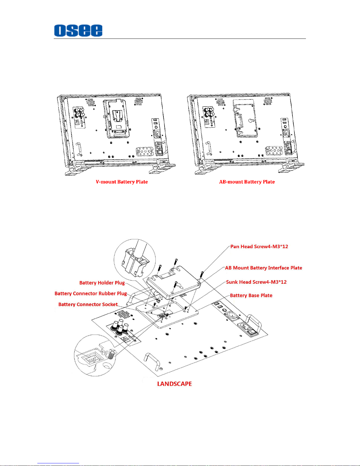
Specifications
63
1. Battery Plate
If you want to use a battery as your backup power supply, you can choose the
battery plate listed in the optional accessories table above, and you can select
two types of battery plate according to your needs: V-mount battery plate or
AB-mount battery plates, as shown in Figure 5.2-1:
Figure 5.2-1 V-mount and AB-mount Battery Plate
There are two kinds of methods for mounting the battery plate: in portrait or in
landscape. For V-mount battery plate, as shown in Figure 5.2-2 and Figure 5.2-3,
and for AB-mount Battery Plate, as shown in Figure 5.2-4 and Figure 5.2-5:
Figure 5.2-2 AB-mount Battery Plate in Landscape
Page 70
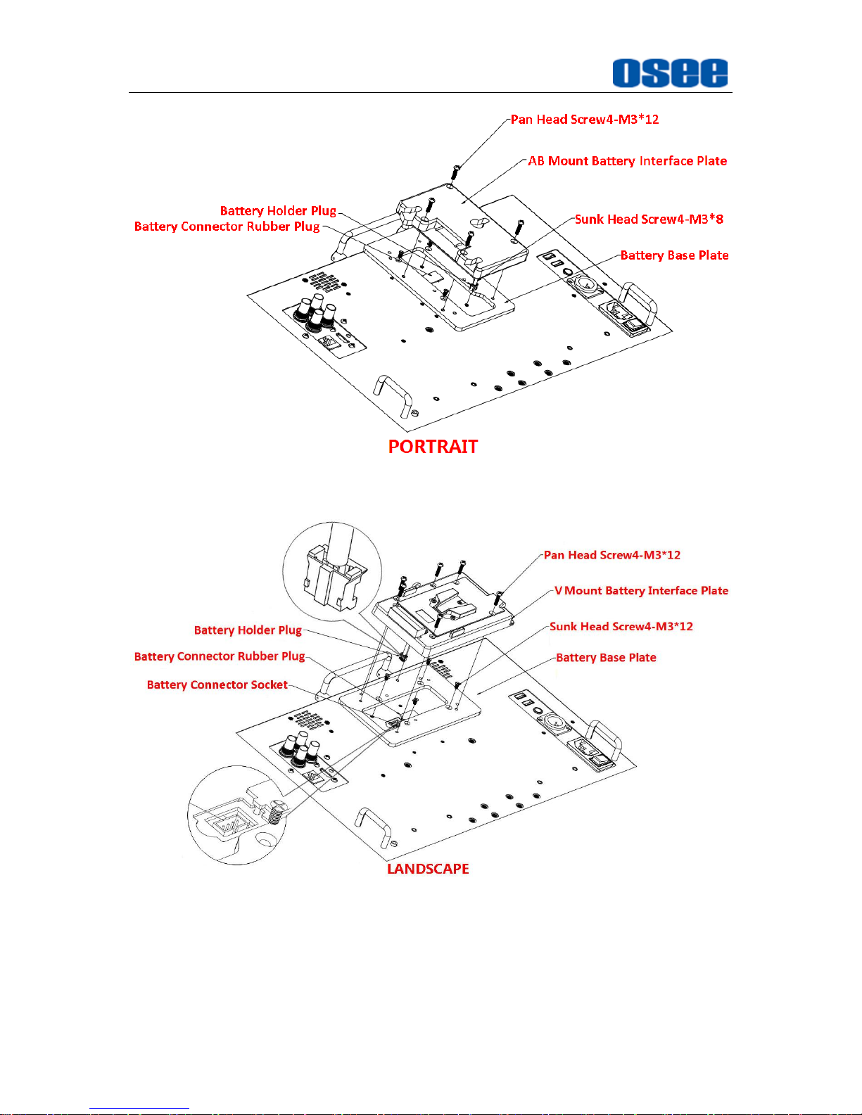
Specifications
64
Figure 5.2-3 AB-mount Battery Plate in Portrait
Figure 5.2-4 V-mount Battery Plate in Landscape
Page 71
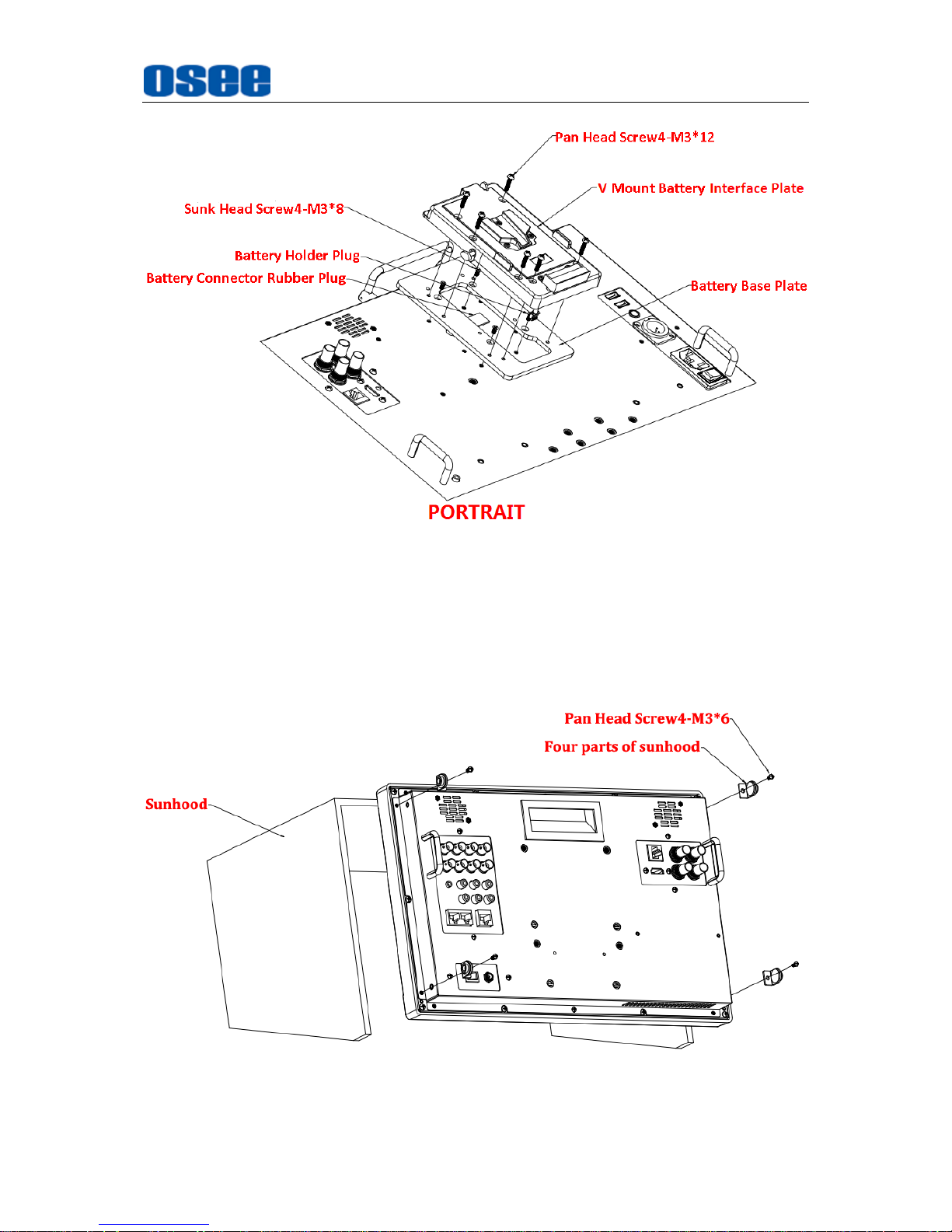
Specifications
65
Figure 5.2-5 V-mount Battery Plate in Portrait
2. Sunhood
In case of diffusion light and direct illumination, we can use sunhood for the
LCM-E series monitors for images supervision. Mount the sunhood as shown in
Figure 5.2-6, Figure 5.2-7, and Figure 5.2-8:
Figure 5.2-6 Mount a Sunhood for LCM-156E
Page 72
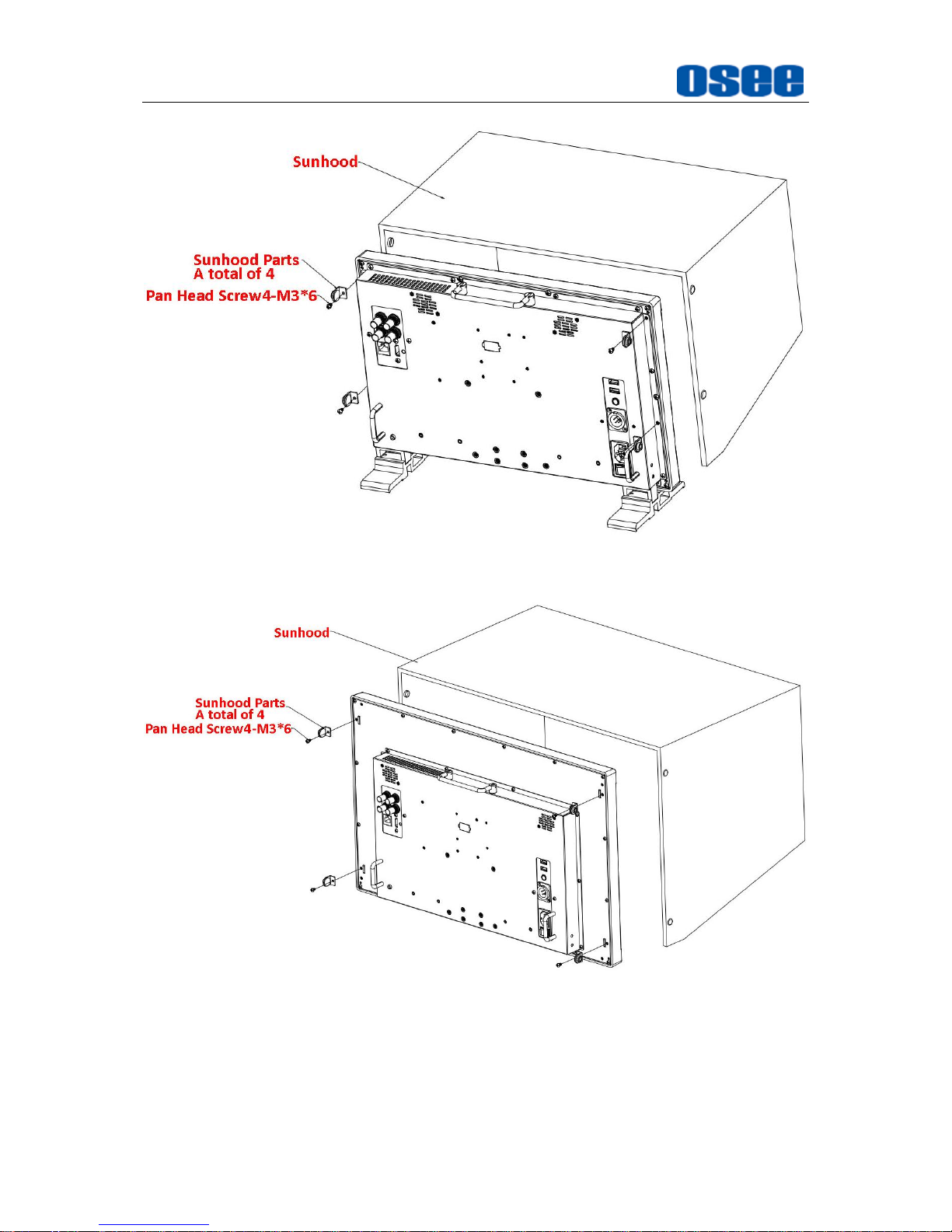
Specifications
66
Figure 5.2-7 Mount a Sunhood for LCM-170E
Figure 5.2-8 Mount a Sunhood for LCM-230E
3. Protective Screen
Choose the protective screen to protect your monitor screen. Mount the
protective screen as shown in Figure 5.2-9, Figure 5.2-10, and Figure 5.2-11:
Page 73
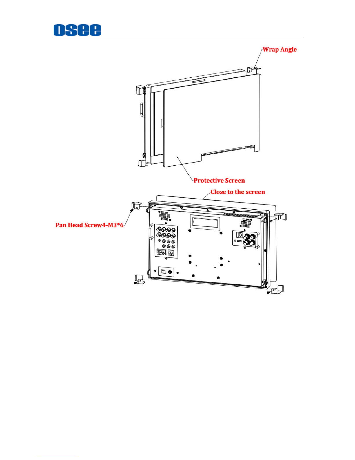
Specifications
67
Figure 5.2-9 Mount a Protective Screen for LCM-156E
Page 74
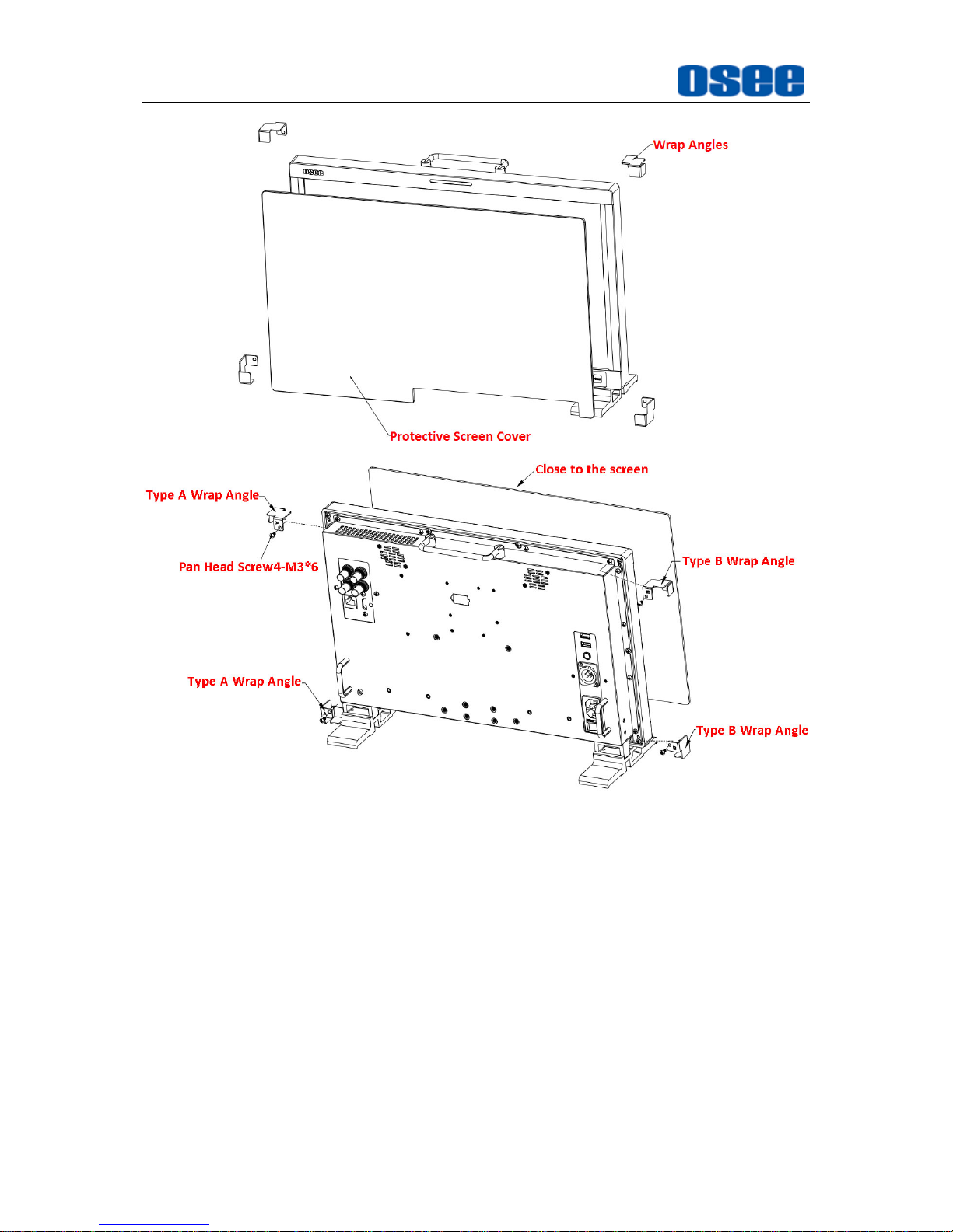
Specifications
68
Figure 5.2-10 Mount a Protective Screen for LCM-170E
Page 75
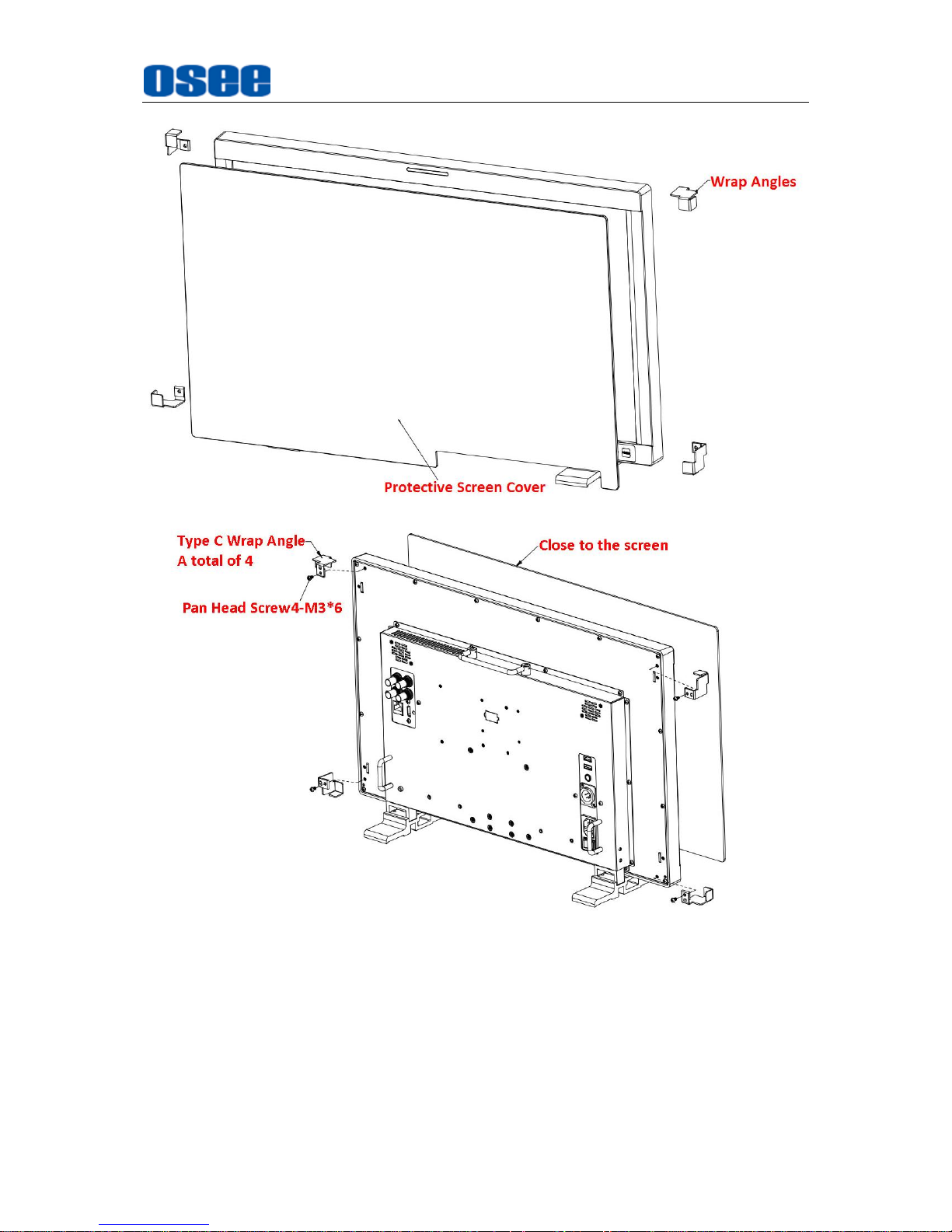
Specifications
69
Figure 5.2-11 Mount a Protective Screen for LCM-230E
4. OSEE Monitor Adapter C-Stand
Each monitor can be mounted to any stand with an OSEE Monitor adapter
C-Stand, the connection method is as shown in Figure 5.2-12, and the usage is
as shown in Figure 5.2-13:
Page 76
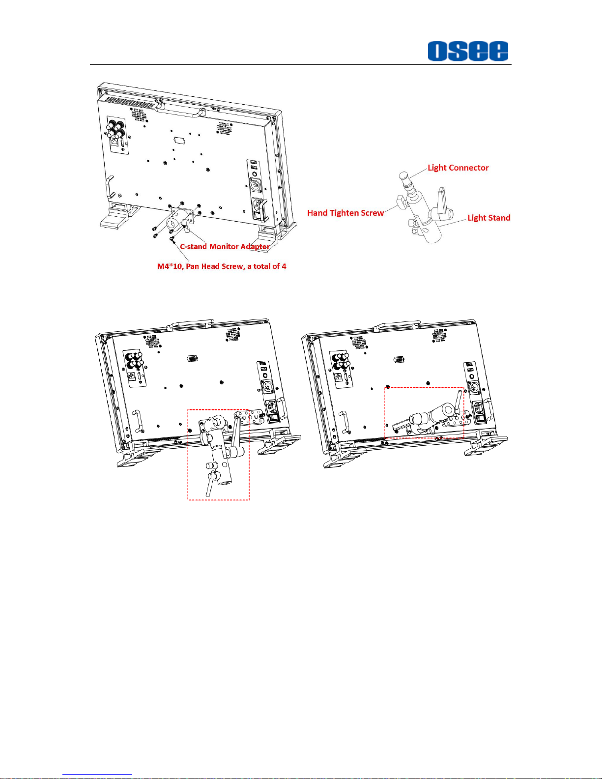
Specifications
70
Figure 5.2-12 Adapter C-Stand to LCM-E Monitor
Figure 5.2-13 Connecting to Light Stand
5. Hanger
It provides an inch screw thread hanger as an optional accessory. The hanger
provides two sorts of screw thread: 3/8 inch screw thread, a total of 4; 1/4 inch
screw thread, a total of 8, as shown in Figure 5.2-14:
Page 77
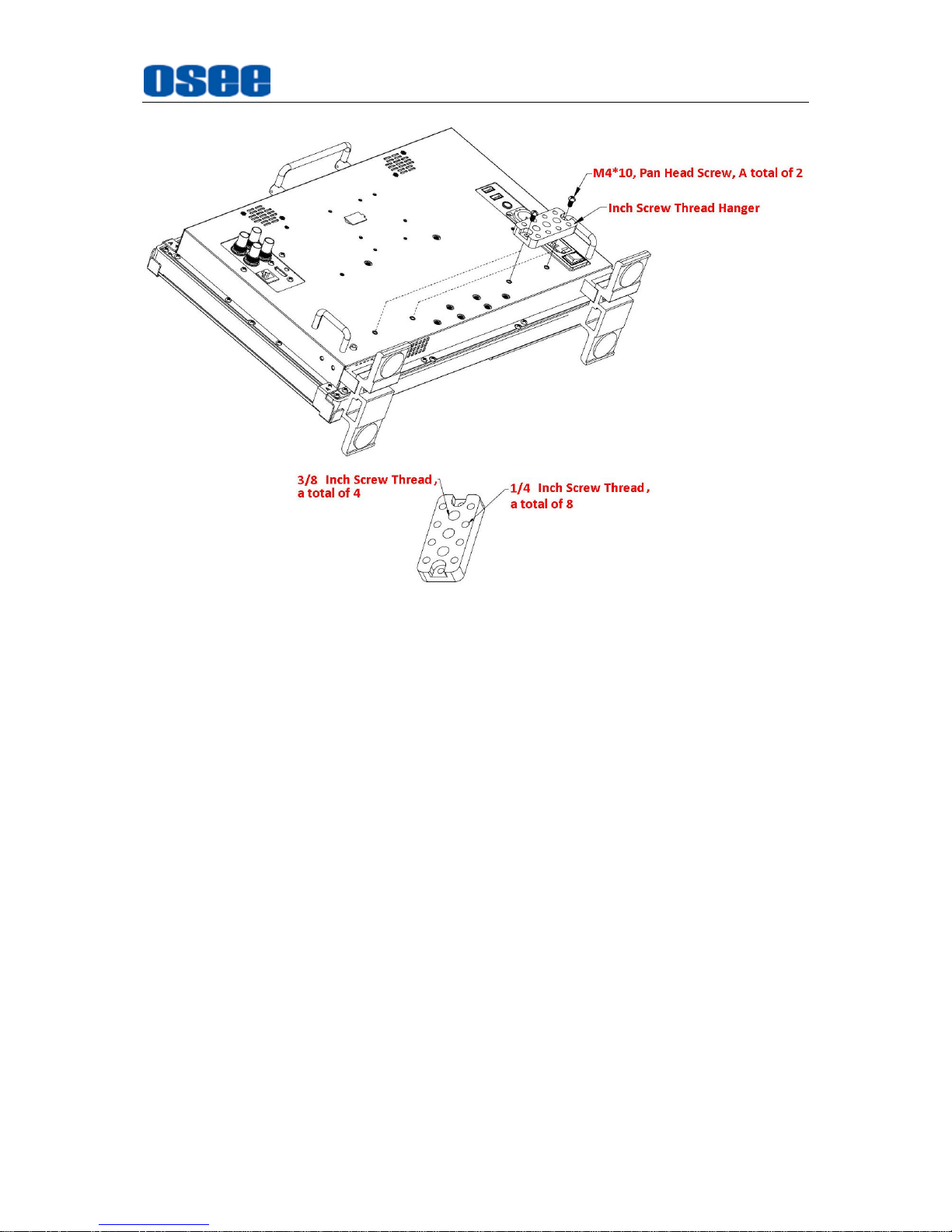
Specifications
71
Figure 5.2-14 Inch Screw Thread Hanger
5.3 Dimensions
The description of the LCM***-E series dimensions are as shown in the following
figures(Unit: mm):
Page 78
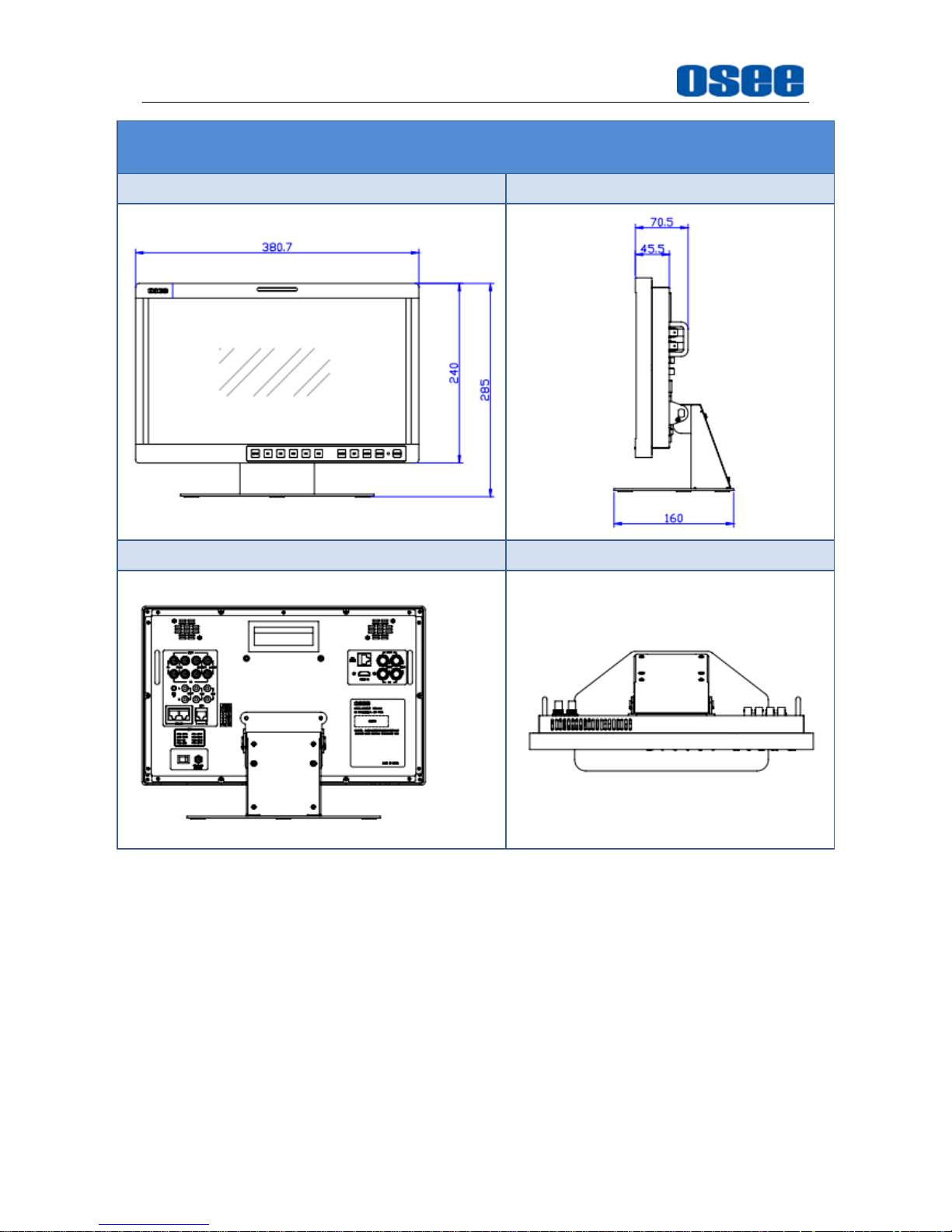
Specifications
72
LCM156-E
Front Panel
Side View
Rear Panel
Top View
Page 79
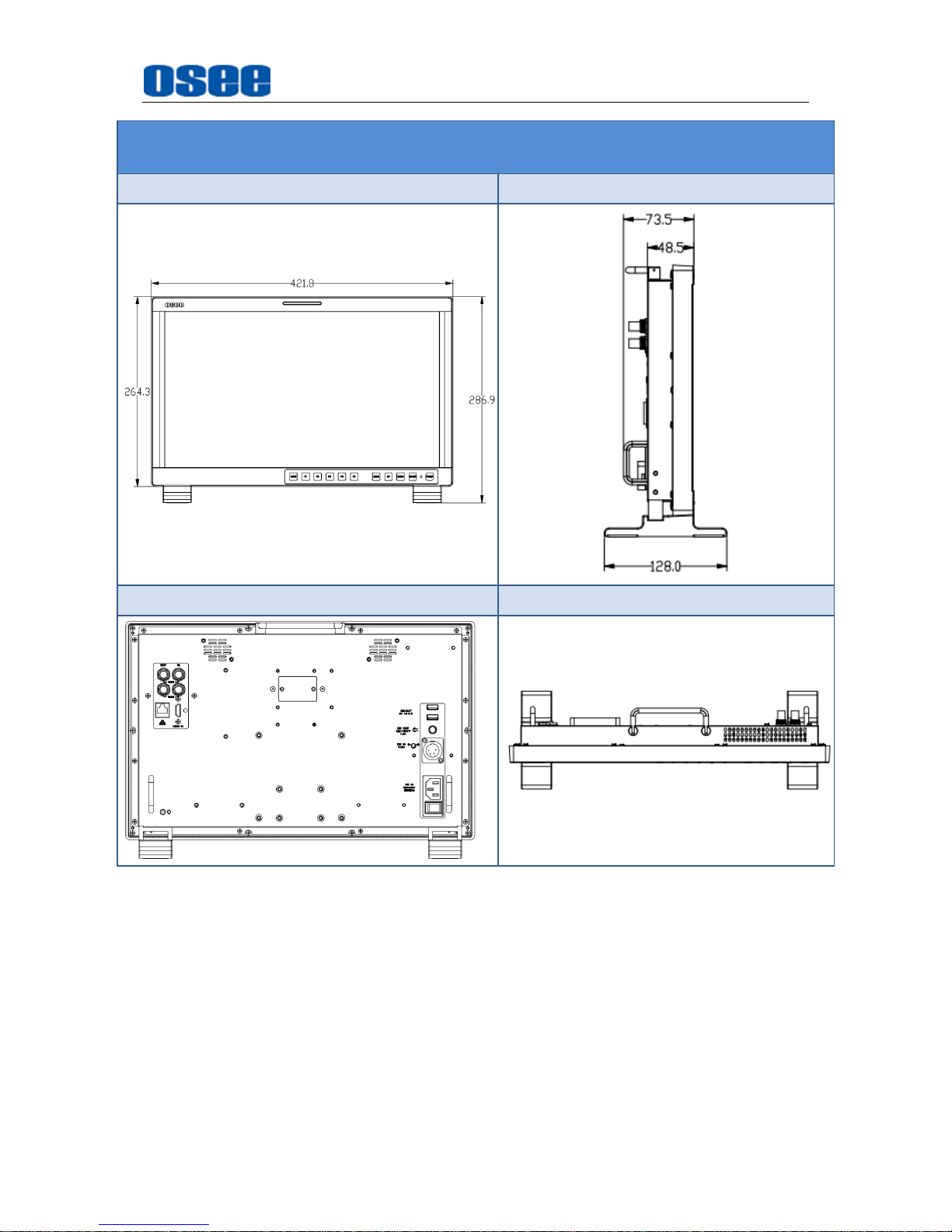
Specifications
73
LCM170-E
Front Panel
Side View
Rear Panel
Top View
Page 80
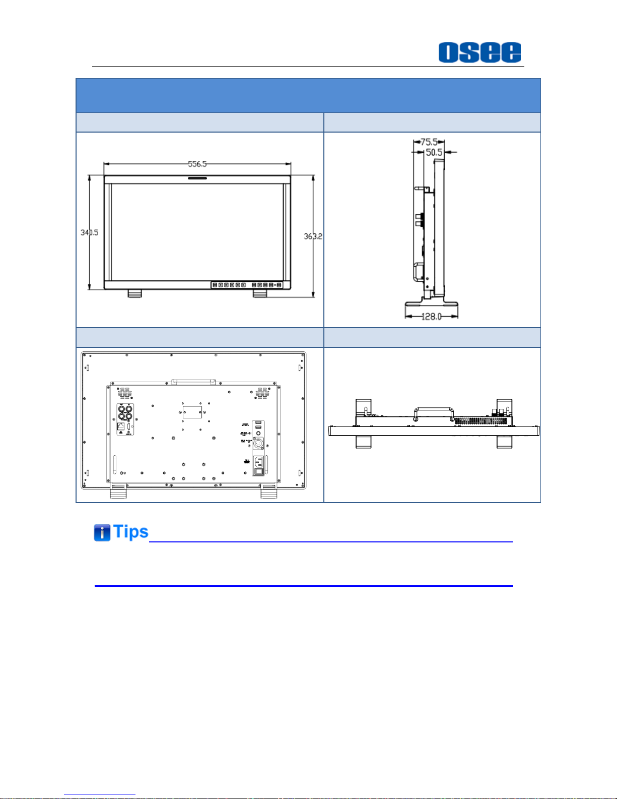
Specifications
74
LCM230-E
Front Panel
Side View
Rear Panel
Top View
Specifications are subject to change without notice.
------------------No Text Below------------------
Page 81

FOR MORE INFORMATION PLEASE VISIT: http://www.osee-dig.com/
OSEE TECHNOLOGY CO., LTD.
Address:
No.22 Building, No.68 zone, Beiqing Road, Haidian District,
Beijing, China
Tel:
(+86) 010-62434168
Fax:
(+86) 010-62434169
FOR MORE INFORMATION PLEASE VISIT: http:/www.oseeamericas.com
OSEE AMERICAS, LTD.
Address: 43218 Christy Street Fremont, CA. 94538
Tel: (+1) 510-996-4499
E-mail: [email protected]
 Loading...