

Page 1

IMP5212
Professional Video Wall
Processor
User Manual
Page 2

Page 3
Product Information
Model:
IMP5212 Professional Video Wall Processor
Version:
V010000
Release Date:
January 9th, 2015
Company
OSEE TECHNOLOGY CO., LTD.
Customer Support
Address:
No.22 Building, No.68 zone, Beiqing Road, Haidian District,
Beijing, China
Post Code:
100094
Tel:
(+86) 010-62434168
Fax:
(+86) 010-62434169
Web:
http://www.osee-dig.com/
E-mail:
Page 4
About this manual
Important
The following symbols are used in this manual:
The further information or know-how for described subjects above which
helps user to understand them better.
The safety matters or operations that user must pay attention to when using
this product.
Contents
The user manual applies to the following device types:
IMP5212
The images of IMP5212 adopted in the following descriptions.
Any of the different specifications between the device types are elaborated.
Before reading the manual, please confirm the device type.
Page 5
Contents
Contents .......................................................................................................... I
Chapter 1 Product Overview ......................................................................... 1
Chapter 2 Safety ............................................................................................. 5
Chapter 3 Unpack and Installation ............................................................... 7
Chapter 4 IMP5212 Features ....................................................................... 13
4.1
Front Panel Features ........................................................................ 13
4.1.1
Touch Screen ................................................................................. 14
4.2
Rear Panel Features .......................................................................... 19
4.2.1
Bus Board ....................................................................................... 21
4.2.2
Input module ................................................................................... 21
4.2.3
Output Module ................................................................................ 26
4.2.4
Control Module ............................................................................... 27
4.3
Device Connection ............................................................................ 32
4.4
Control Access .................................................................................. 33
4.5
Control Instruction Set ..................................................................... 34
Chapter 5 Specifications ............................................................................. 37
Page 6

Page 7

Product Overview
1
Chapter 1 Product Overview
The professional Video Wall Processor, IMP5212, provides by OSEE, offers
the ideal and practical 24/7 robustness, it provides perfect visual effects, high
security, flexible operating environment and easy in configuration and
maintenance.
The IMP5212 is a professional Video Wall Processor offering a multi-monitor
display environment suited to your system by selecting and installing the
required input and output modules in a 7U frame. Up to 13 input and 3 output
cards can be installed on the frame, for a Video Wall Processor with a
maximum of 26 inputs and 12 outputs. Supports mixed input of analog
composite, VGA, SDI, HDMI, YPbPr and DVI.
It is widely used in the following fields: educational and research, public
announcement, publication and information, administrative management,
military command system, exhibition and presentation, security surveillance
system, appliances sales etc.
The IMP5212 Video Wall Processor and its inner control software compose the
Video Wall system, the device integrates an internal control software to
connect to and configure the controller. You can configure multi-screen and
multi-presets with the input video sources, and set them at any position and in
arbitrary size in the operating interface of the software. Each video window has
adequate resolution to show very high quality frame effects. The software is a
WYSIWYG editor and easy to use.
Figure 1-1 The Illustration of IMP5212 Video Wall Processor
Page 8
Product Overview
2
IMP5212 Video Wall Processor supports the following features:
Features
Supports up to 26 windows displayed through a single output channel,
with image zoom, overlay, roaming, and cross-screen displayed.
Supports up to 12 screens to be grouped together as the monitor wall.
When there are 12 channels of video outputs, the layout of the screens
could be up to the 3X4 format.
Supports up to 26 channels of video input signals(adaptive), which
supports several formats: DVI, VGA, HDMI, SDI, CVBS, S-Video and
YPbPr, a wide range of graphics inputs with resolutions up to 1920 x
1200 and 2048 x 1080p at 60 Hz frame rate(using the specific DVI
interface with the DVI-M technology owned by OSEE).
Supports up to 12 channels of video outputs with DVI-D interface, the
output resolution can be up to 1920X1200@60P and 2048X1080@60P,
each output could be displayed across several display screens, in a
single screen or in full screens.
Image can be displayed anywhere, any size, within or cross screens.
The window of a video source can be moved from one screen to
another screen in real time
Supports power distribution through GPO interface
Provides character superimposition, it is available in any window
Supports background, and 4 customized backgrounds.
Supports EDID bypass management of non-standard signal sources
Provides timing with system time.
Using professional case for high reliability
Supports plenty of inner scene models to realize the effects of roaming,
overlapping, zooming and so on
Using the advanced dynamic interlace analysis technology to achieve
high-quality video.
Input expansion can be achieved by adding an external matrix router.
Functionality
Supports integrated luminance control with high reliability and
excellent stability, using the new high speed parallel processing
method to display high quality images without trailing or jag.
Using professional frame for high reliability with redundant power
supplies.
Supports hot swap of input modules and output modules, to realize
expansion online.
Page 9
Product Overview
3
The input transmission is real-time without delay
Supports up to 50 customized scene models, including position, size
and stacked relationship of the input video windows.
Supports several control methods: RS232 control, color touch screen
and remote control computer(TCP/IP)
Provides a color touch screen in front panel for touch control
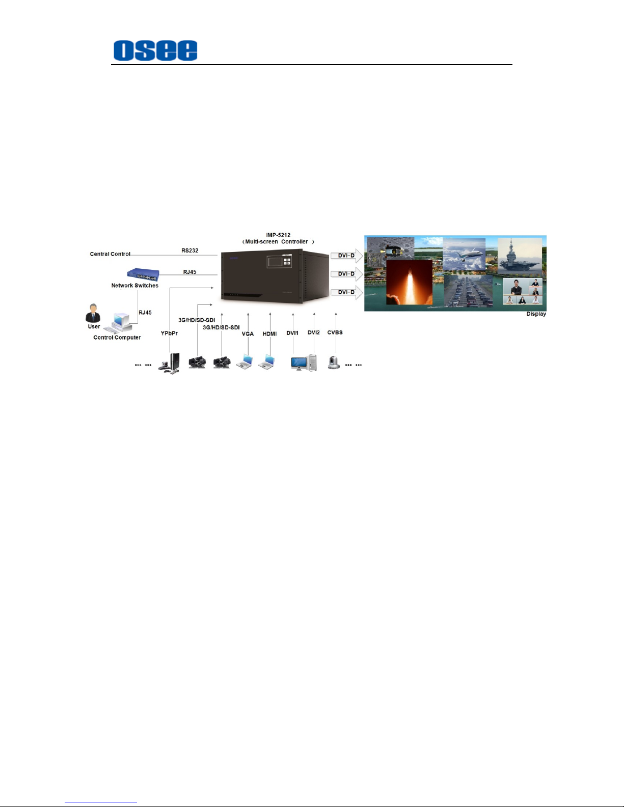
Application example
Figure 1-2 The example for IMP5212 Application
Page 10

4
Page 11
Safety
5
Chapter 2 Safety
FCC Caution:
Any Changes or modifications not expressly approved by the party responsible
for compliance could void the user's authority to operate the equipment.
This device complies with part 15 of the FCC Rules.
Operation is subject to the following two conditions: (1) This device may not
cause harmful interference, and (2) this device must accept any interference
received, including interference that may cause undesired operation.
Note: This equipment has been tested and found to comply with the limits for a
Class B digital device, pursuant to part 15 of the FCC Rules. These limits are
designed to provide reasonable protection against harmful interference in a
residential installation. This equipment generates uses and can radiate radio
frequency energy and, if not installed and used in accordance with the
instructions, may cause harmful interference to radio communications.
However, there is no guarantee that interference will not occur in a particular
installation. If this equipment does cause harmful interference to radio or
television reception, which can be determined by turning the equipment off and
on, the user is encouraged to try to correct the interference by one or more of
the following measures:
Reorient or relocate the receiving antenna.
Increase the separation between the equipment and receiver.
Connect the equipment into an outlet on a circuit different from that to which
the receiver is connected.
Consult the dealer or an experienced radio/TV technician for help.
Page 12
Safety
6
Warnings:
Read, keep and follow all of these instructions for your safety. Heed all
warnings.
Video Wall Processor
Upgrading of the device is subject to change without notice.
Contact your Customer Service representative if parts are missing or
damaged.
Position
Do not block any ventilation openings.
Do not use this unit near water.
Do not expose the unit to rain or moisture.
Do not install near any heat sources such as radiators, heat registers,
stoves, or other apparatus (including amplifiers) that product heat.
A nameplate indicating operating voltage, etc., is located on the rear
panel.
The socket-outlet shall be installed near the equipment and shall be
easily accessible.
Page 13
Unpack and Installation
7
Chapter 3 Unpack and Installation
Unpack
When unpacking the components of this switcher, please verify that none of
the components listed in Table 3-1 are damaged or lack. If there is any missing,
contact your distributors or Beijing Osee Digital Technology Ltd. for it.
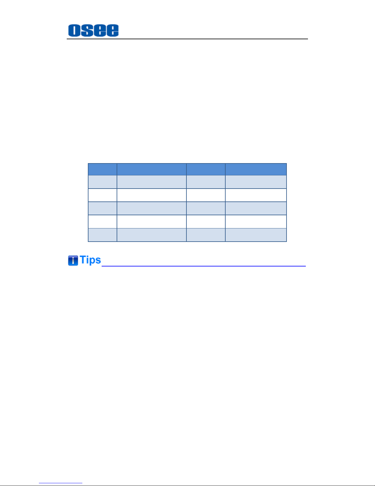
Table 3-1 Packing List
No.
Item
Quantity
Comments
1
Video Wall Processor
1
IMP5212
2
Disk
1
User manuals
3
Certificate Card
1
4 Warranty Card
1
5
Power Cord
1
About Unpacking and Shipping
This product was carefully inspected, tested, and calibrated before
shipment to ensure years of stable and trouble-free service. Before
you install this unit, do the followings:
Check the equipment for any visible damage that may have
occurred during transit.
Confirm receipt of all items on the packing list.
Contact your dealer if any item on the packing list is missing.
Contact the carrier if any item is damaged.
Remove all packaging material from the product before you install
the unit.
Page 14
Unpack and Installation
8
Retain at least one set of the original packaging materials, in the
event that you need to return a product for servicing.
If the original package is not available, you can supply your own
packaging as long as it meets the following criteria:
The packaging must be able to withstand the product’s weight.
The product must be held rigid within the packaging
There must be at least 5 cm of space between the product and the
container.
The corners of the product must be protected.
Ship products back to us for servicing prepaid and, if possible, in the
original packaging material. If the product is still within the warranty
period, we will return the product prepaid after servicing.
Installation
The IMP5212 video wall processor has already been assembled
according to the customer's requirements. You can follow the instructions
below to replace the corresponding module when need to replace or
expand your processor.
1. Preparations
Make sure you have prepared the followings before replace the modules:
Inspect for any apparent physical damage that may have occurred in
transit.
Make sure you have received all the components listed in packing list.
if there are any anti-static package or other packages, please take off
them.
Keep the package in case of future usage.
The safety matters or operations that user must pay attention to when using
this product.
Check out the consumption of module and the maximum power of frame
before installation.
Page 15
Unpack and Installation
9
Ensure that all handling precautions are taken to avoid electrostatic
discharge or other damage to sensitive electronic components. Wear an
earth strap and perform all PCB assembly at an appropriate anti-static work
station. Follow the instructions carefully to fit the modules.
2. Replace the module
Follow the following steps to replace a module:
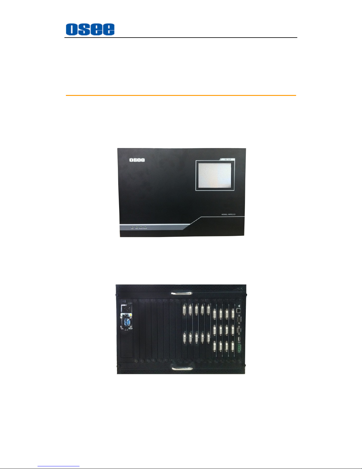
At first, check the frame. Check the rear panel of the frame, as shown in
Figure 3-1.
Figure 3-1 Rear Panel-Insert the Rear Connector
Then, turn round to the rear part of the frame, as shown in Figure 3-2, you
can see the power module and the bus board have been installed.
Figure 3-2 Rear Panel
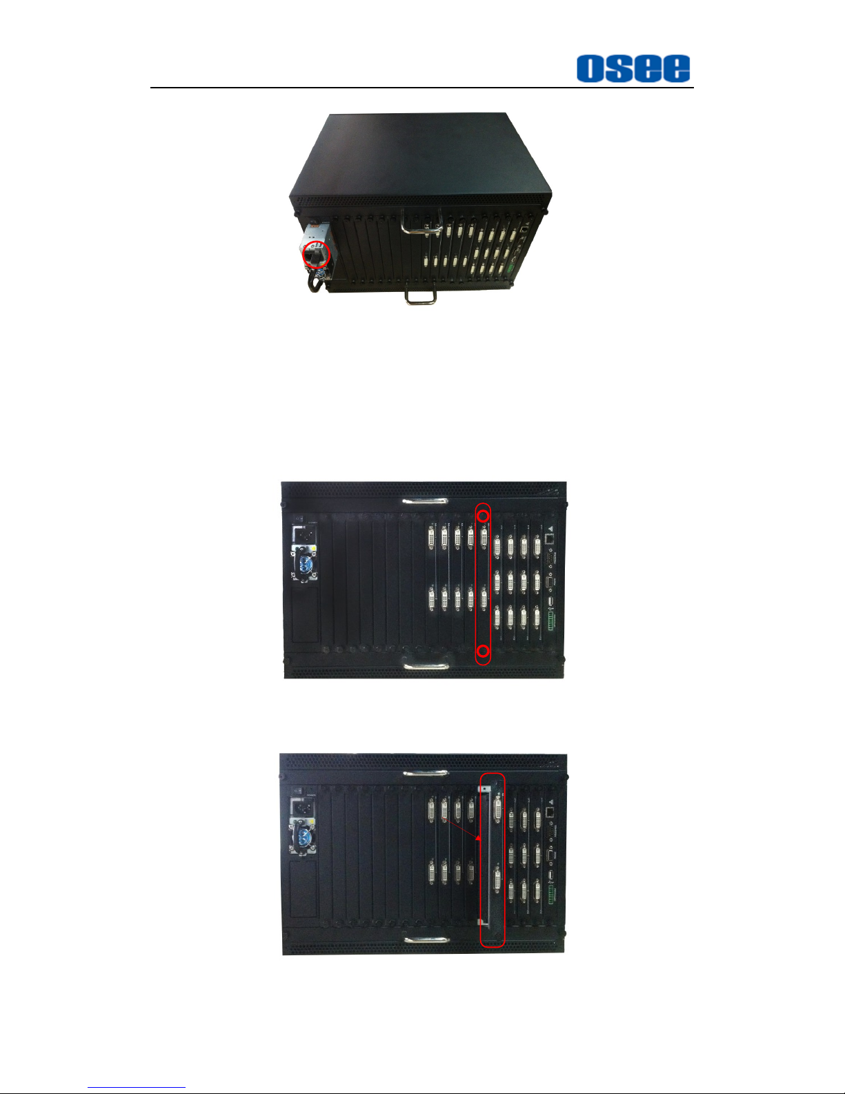
You can see the swivel handle of the power module labeled in red circle,
as shown in Figure 3-3, you can press it down to pull the power module
out of the frame.
Page 16
Unpack and Installation
10
Swivel
Handle
Figure 3-3 The Swivel Handle of the Power Module
Step 1 Remove the old module
Take an input module for example, loosen the screws, as shown in Figure
3-4, and then pull out the module along the slot of the frame, as shown in
Figure 3-5.
screw
screw
module
Figure 3-4 Loose the Module
Pull Out the Module
Figure 3-5 Pull Out the Old Module
Page 17
Unpack and Installation
11
Step 2 Replace a new module
Then, push the new module slightly along the slot, press module
again to confirm that the module is installed firmly and then fasten
the screws.
Please make sure the module type and the slot position must be
matched with each other. Install the other modules as the same
steps.
Page 18

12
Page 19
IMP5212 Features
13
Chapter 4 IMP5212 Features
This chapter describes the features of IMP5212.
4.1 Front Panel Features
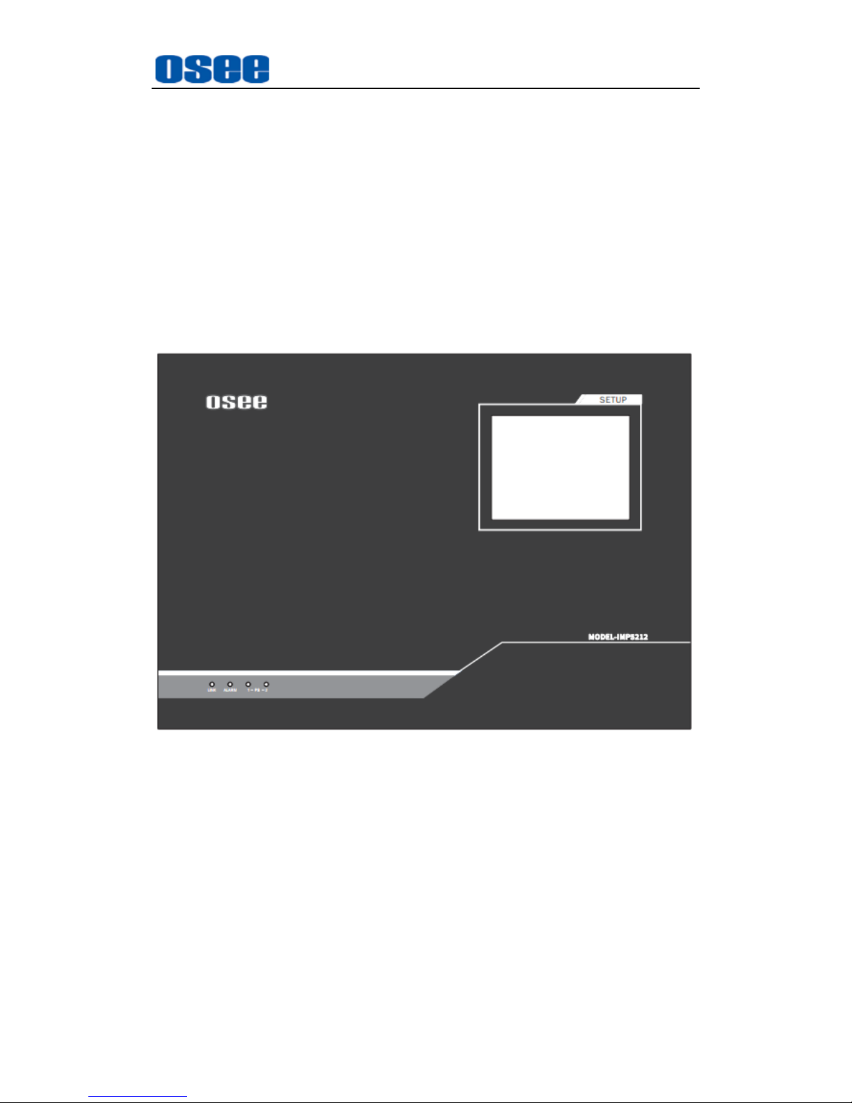
There are four indicators in the center of the front panel, as shown in
Figure 4.1-1
Figure 4.1-1 the Buttons in Front Panel
1. Link
Communication indicator. It indicates the communication status between
the video wall processor and the control computer. The indicator is lighting
when the communication has been set up and been normal, or it will flash
when the communication has not been set up or some communication
faults happens.
2. Alarm
Case Temperature alarm indicator. It lights up to indicate the temperature
of case is higher than the limitation, and it is off when temperature is
normal.
Page 20
IMP5212 Features
14
There are two groups of fans positioned at the top and bottom of the frame.
Please check the fans' status when the case temperature alarm happens.
The fans support hot swap.
3. PS1 Indicator
It is used to indicate the PS1 power on or off. If the light is green, the
device is powered on, and if the light is off, the device is powered off.
4. PS2 Indicator
It is used to indicate the PS2 power on or off. If the light is green, the
device is powered on, and if the light is off, the device is powered off.
4.1.1 Touch Screen
There is a touch screen at the top right corner of the front panel, and you
can do the following operations through this touch screen.
Preset Call
GPO Control
Language Selection
Running Time
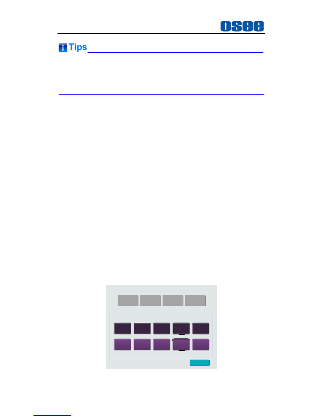
1. Preset Call
Preset Call is used to switch to and apply one of the former 20 presets.
They are distributed in two pages, each page contains 10 buttons and
each button is a preset, then turn pages using the previous page and the
next page button to check the contents.
预案调用 GPO控制 语言选择 运行时间
预案模板
1 2 3 4 5
6 7 8 9 10
下一页
Figure 4.1-2 Preset Call
Page 21
IMP5212 Features
15
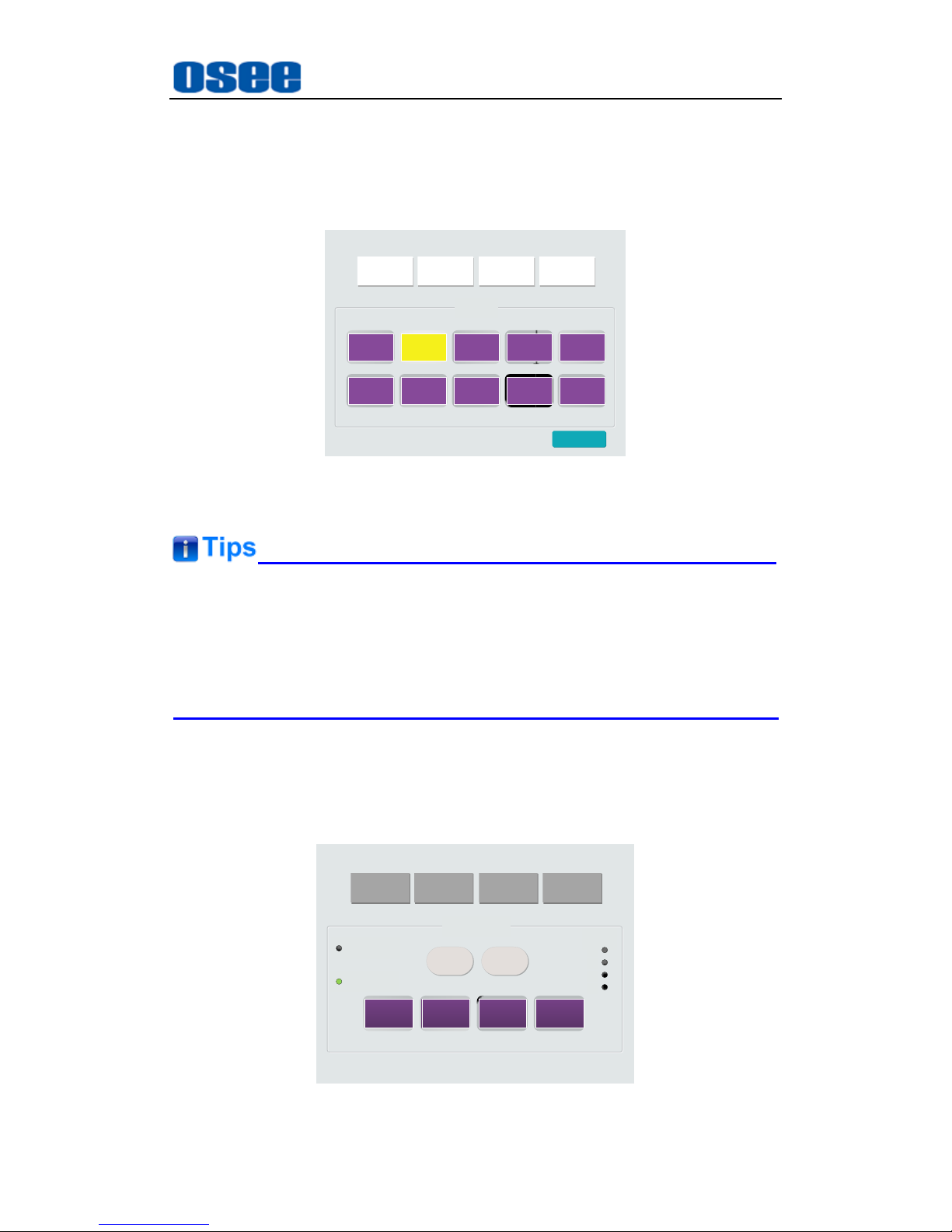
Operation
: click the
Preset Call
button, and it will display the preset call
interface at the center of the touch screen. Click a numbered preset
button to switch to the corresponding preset, and the button color turn
purple from yellow. For example, as shown in Figure 4.1-3, the twentieth
preset displays.
预案调用 GPO控制 语言选择 运行时间
预案模板
11 12 13 14 15
16 17 18 19 20
上一页
Figure 4.1-3 Selecting a Preset
Up to 50 presets can be preview, and the touch screen provides the former
20 presets for fast switching operation. Refer to the manual for OSEE
Video Wall System control software for the details about the preset
definition.
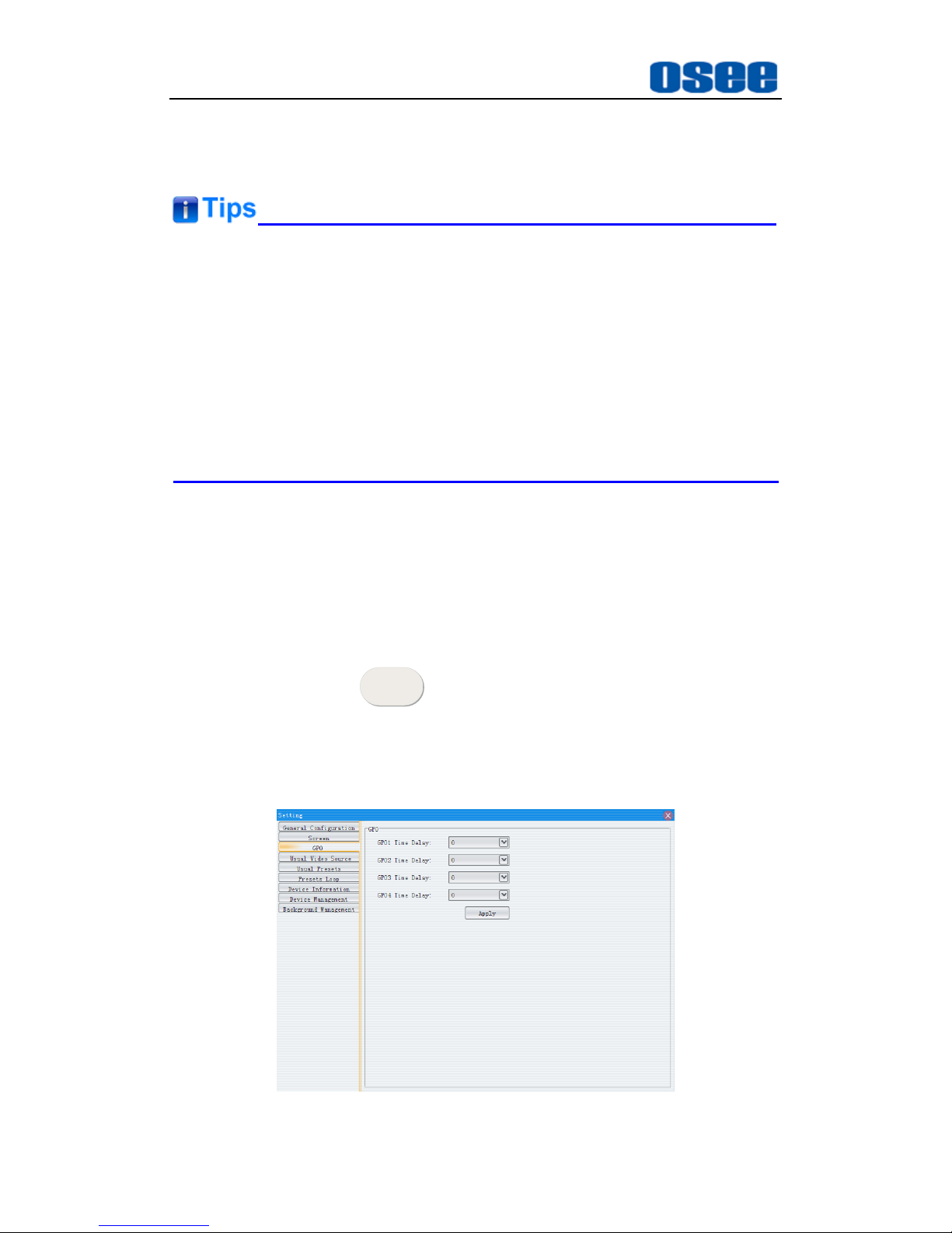
2. GPO Control
GPO Control is used to set to turn on or off the display screens through
automatic control method or manual control method, the operation
interface is shown in Figure 4.1-4:
预案调用 GPO控制 语言选择 运行时间
GPO控制模板
第一通道
第二通道 第三通道 第四通道
自动控制
手动控制
启 动
启 动
停 止
停 止
状态指示
1
2
3
4
Figure 4.1-4 GPO Control
Page 22
IMP5212 Features
16
Select from automatic control mode or manual control mode to control the
turn on or off the display screens in GPO Control interface, and the
indicator of the screen will turn green when it is turned on.
In IMP5212, GPO control is realized through the GPO interface of its
control module. The GPO interface connect the video wall processor and
the display screens with its four groups of inner low voltage relays, thus to
control open or close of the connected devices. Each group of inner low
voltage relays controls one device, and one to one correspondence with
one of the four accesses.
The GPO interface will apply to the devices conformed to its contact rating.
Automatic control mode
The automatic control mode contains two control buttons: Startup button
and Stop button, and they direct to the starting logic and the stopping logic
separately, the instructions are as follows:
Startup
Click Startup button
启 动
启 动
, IMP5212 will start up the open logic, the
No.1~No.4 access should be set a delay time for the open sequence. The
delay time is accumulative by the GPO sequence.
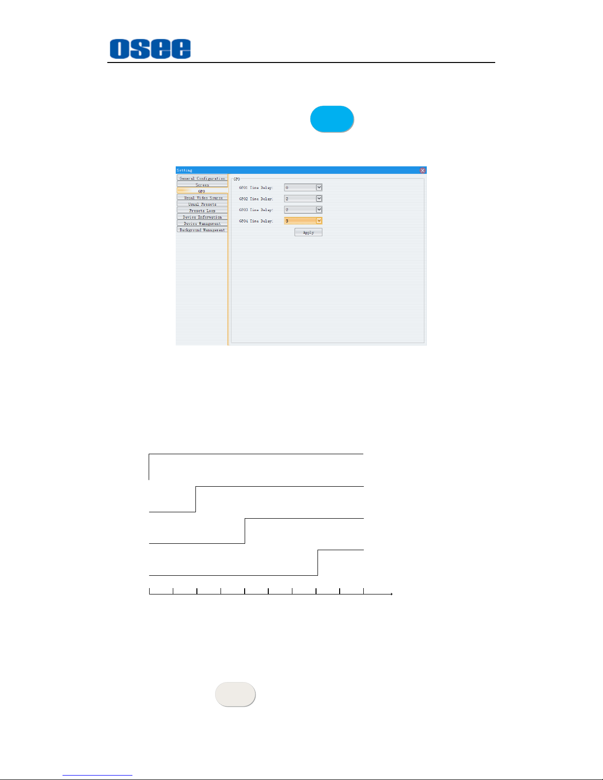
The delay time for No.1~No.4 access should be set separately to GPO1(s)
~GPO4 (s), in Settings window, as shown in Figure 4.1-5:
Figure 4.1-5 GPO Control Settings
Page 23
IMP5212 Features
17
For example: as shown in Figure 4.1-6, set the delay time for each screen
controlled through the GPO interface.
Click Startup button, it will turn blue
启 动
启 动
and the automatic control
mode is started up. IMP5212 will open the No.1~No.4 screen according to
these GPO delay time.
Figure 4.1-6 Set the Delay Time for GPO Control
The No.1 screen will open at once for its GPO1 is 0 second, and The No.2
screen will open at 2 second, then is the No.3 screen, opens at 4 second,
and the No.4 screen at 7second, the timing sequence logic is as shown in
Figure 4.1-7:
TIME
0
1 2 3 4 5 6 7 8 9
GPO1
GPO2
GPO3
GPO4
Figure 4.1-7 GPO Control Logic-Turn On
Stop
Click Stop button
停 止
停 止
, it will turn off all of the No.1~No.4 screens at
Page 24
IMP5212 Features
18
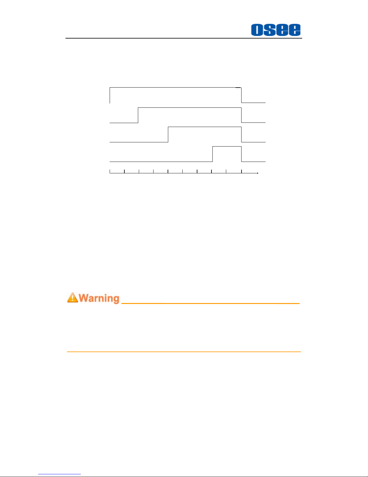
the same time without delay.
For example: take up the example, all of the No.1~No.4 screens turn off at
9 second the time you clicked the stop button. The timing sequence logic
is as shown in Figure 4.1-8:
TIME
0
1 2 3 4 5 6 7 8 9
GPO1
GPO2
GPO3
GPO4
Figure 4.1-8 GPO Control Logic-Turn Off
Manual control mode
The manual control mode contains 4 control buttons: No.1 access to No.4
access, and they direct to the starting logic and the stopping logic
separately for each corresponding access.
For example: click No.1 access button, it will make contact of the first
group of relay, so the connected No.1 screen will be turned on; then click
this button again, it will break up the contact, and the No.1 screen will be
turned off. The other buttons are as the same, and you can check the
status of the corresponding screen by the device indicator at this interface.
If you have started up a controlled device by clicking the Startup button of
automatic control mode, you can’t use the access button in manual control
mode, it is invalid.
3. Language Selection
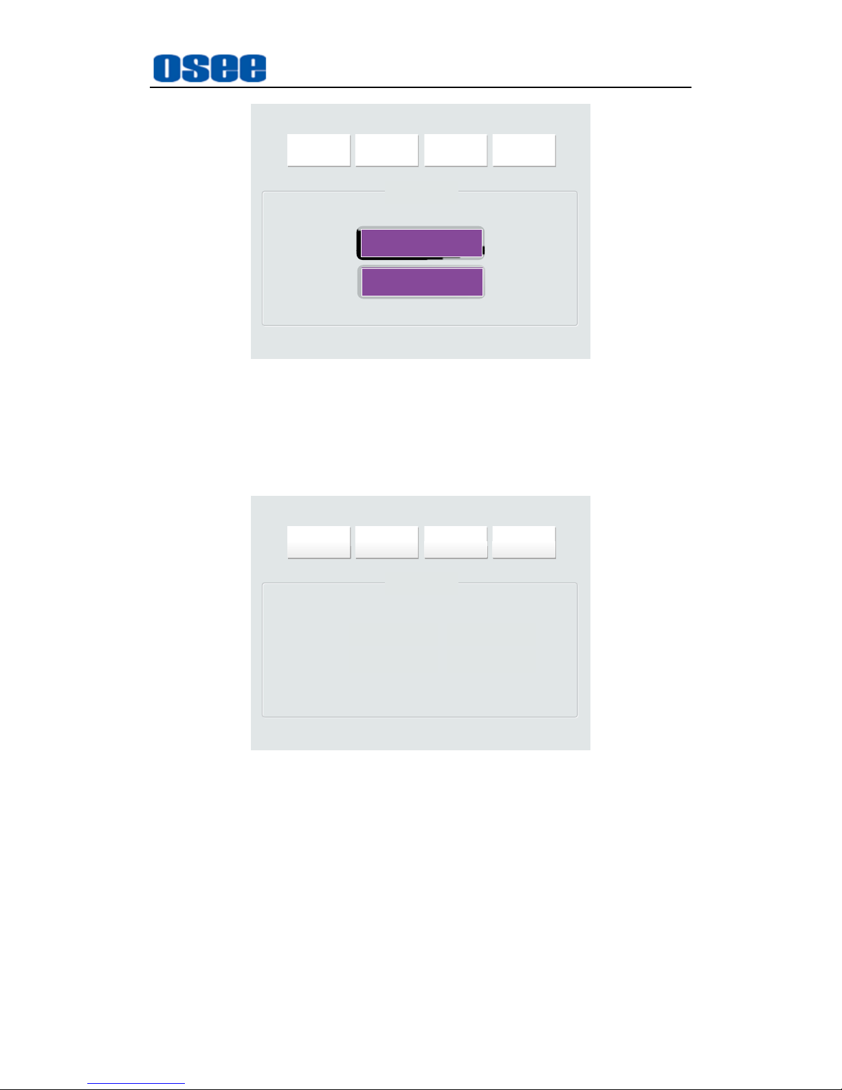
Language Selection is used to selecting the display language of the touch
screen: Chinese or English. The interface is shown in Figure 4.1-9, click
the language button to set the corresponding language.
Page 25
IMP5212 Features
19
预案调用 GPO控制 语言选择 运行时间
语言设置模板
简体中文
English
Figure 4.1-9 Language Selection
4. Running Time
Running Time is used to check the total times of starting up and the total
time of device running, the interface is shown in Figure 4.1-10.
预案调用 GPO控制 语言选择 运行时间
运行时间
累计开机次数:
累计运行时间:2次48小时
Figure 4.1-10 Running Time
4.2 Rear Panel Features
It will introduce the arrangement and the operations of the interfaces in rear of
the panel in the following.
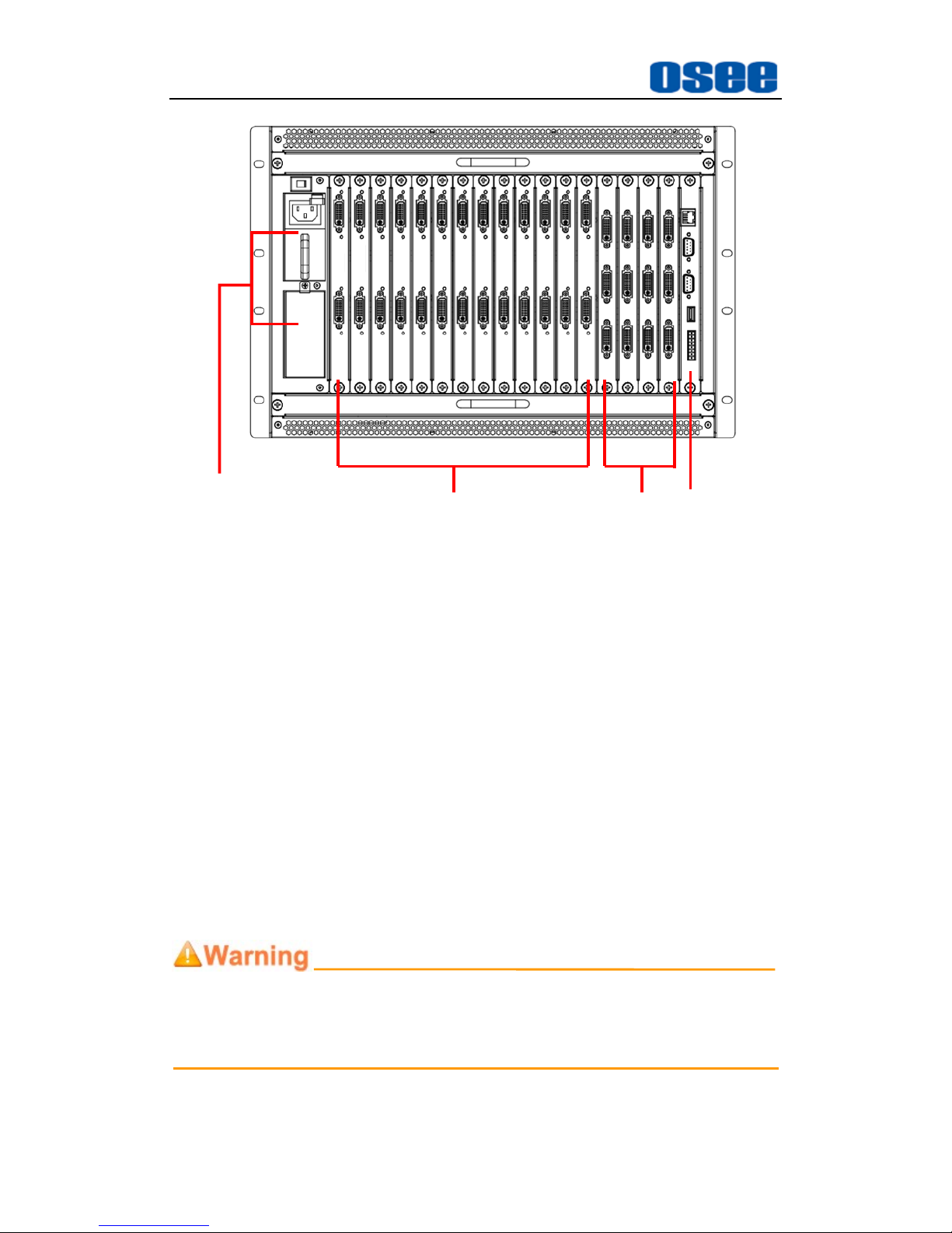
As shown in Figure 4.2-1, IMP5212 provides the various connectors for power
supply, input, output and control, the details are as below:
Page 26
IMP5212 Features
20
POWER
MODULES
INPUT
MODULES
OUTPUT
MODULES
CONTROL
MODULE
Figure 4.2-1 The Rear Connector of IMP5212
The video wall processor performs the power supply, input, output and control
functions through the corresponding modules, and you should make sure the
module has been inserted to the correct slot in the frame. Facing at the
direction of the front panel, the arrangement sequence of the modules from left
to right is power supply module, input module, output module and control
module. Each slot has an attribute, you can see the slots are different on bus
board.
Power Module
It is used to supply AC power. There are two power input interfaces, and
the specification is 100-240V, 50/60Hz, 300W. They are labeled as PS1,
PS2 separately. The corresponding indicators are at the front panel. If the
light is green, the device is powered on, and if the light is off, the device is
powered off.
Only use the adapter and the power cord specified by the manufacture for
your safety!
Page 27
IMP5212 Features
21
4.2.1 Bus Board
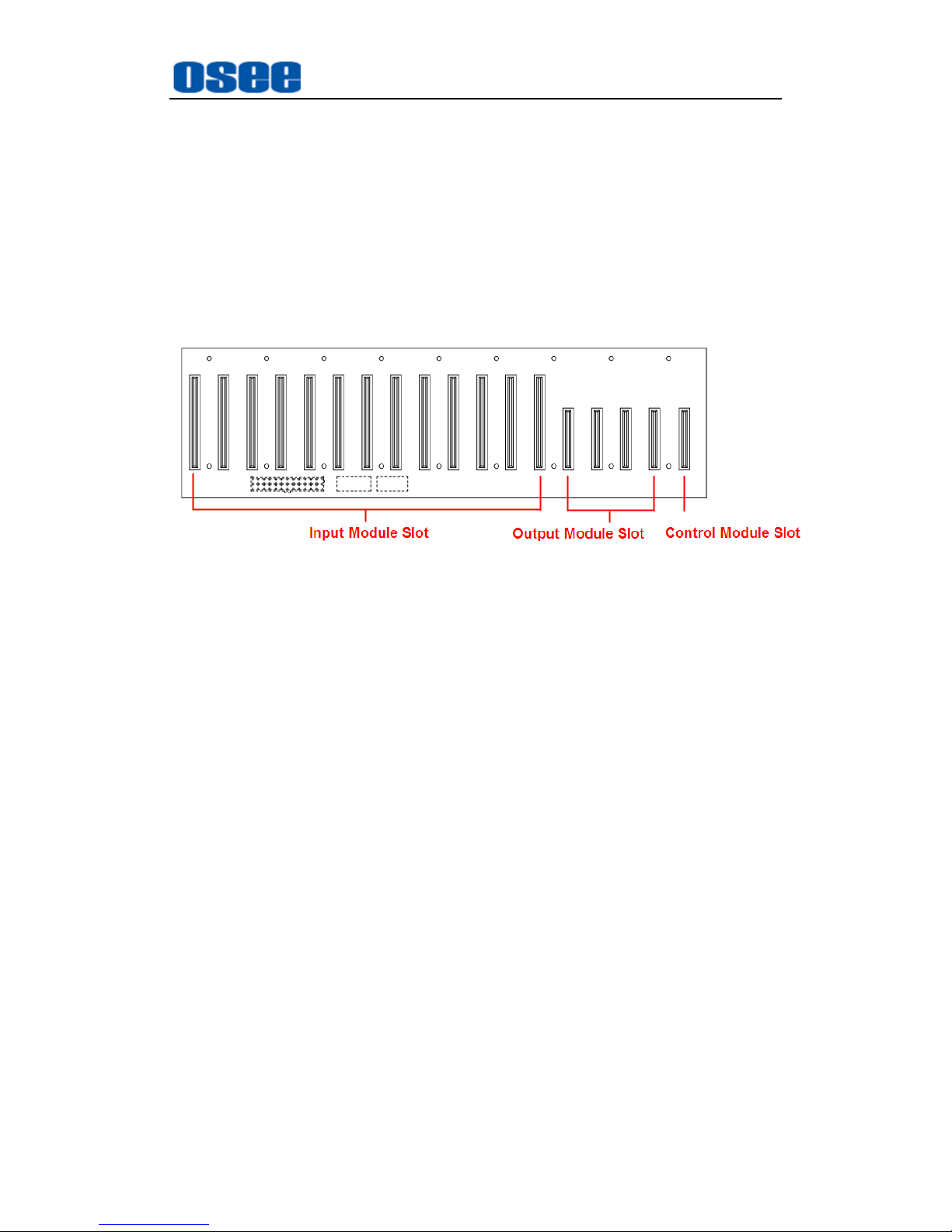
IMP5212 uses the bus board to integrate input module, output module and
control module, and the modules should be positioned into slots differently
according to the module types, then the transmission between them will
be normal.
The bus board provides the transmission paths, the power modules
provide the power supply, and the fans provide the cool running inner
environment.
Figure 4.2-2 The Bus Board of IMP5212
The inserted sequence and amount of the modules from right to left are as
follows:
Control module: 1
Output module: 4 (the most)
Input module: 13(the most)
4.2.2 Input module
IMP5212 provides an input module. Each input module supports two DVI
inputs. The input module is cooperated with its matched input module
panel, as shown in Figure 4.2-3.
Input Module
Page 28
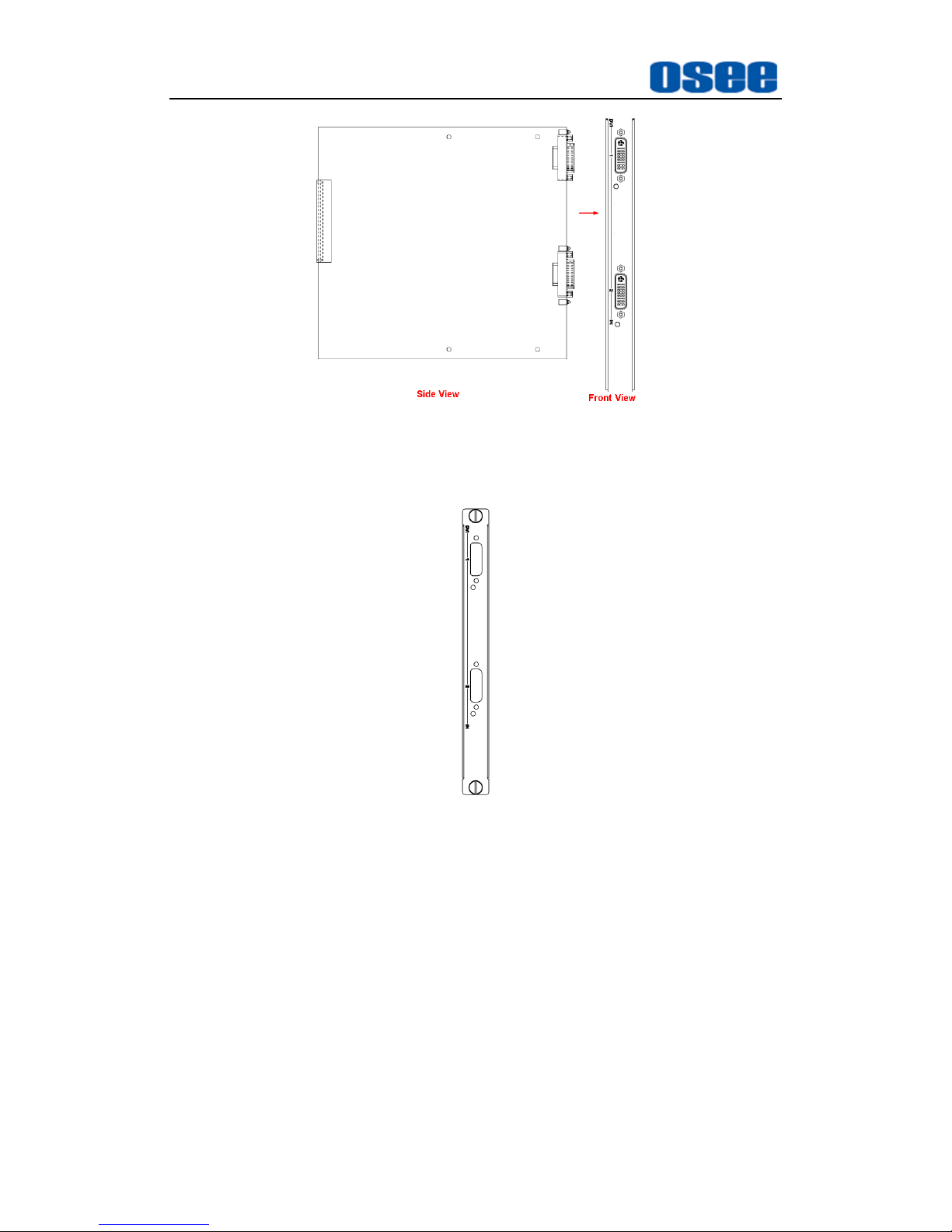
IMP5212 Features
22
Figure 4.2-3 Input Module (Side View)
Panel for Input Module
Figure 4.2-4 Panel for Input Module (Front View)
After insert the input module into the corresponding slot, and put the panel
onto the interfaces of the input module, fasten the screws to fix the module
and its panel, the combination of them are shown in Figure 4.2-5:
Page 29
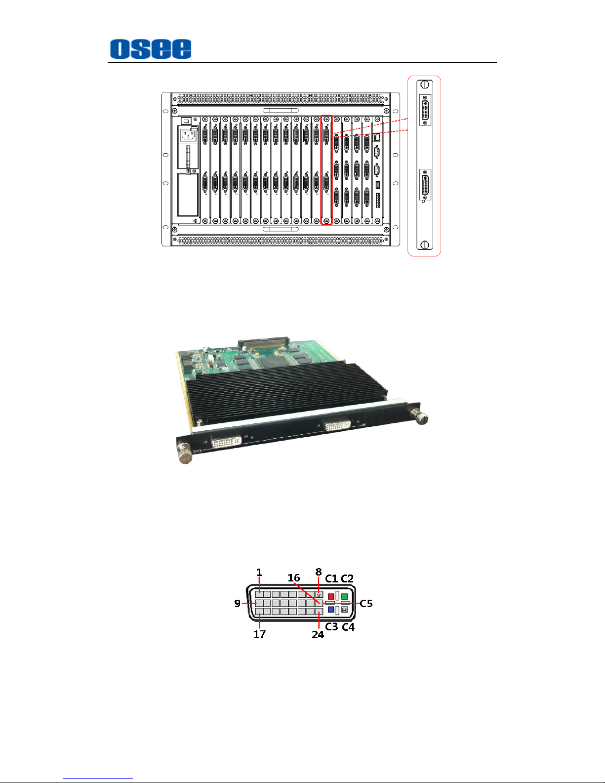
IMP5212 Features
23
Figure 4.2-5 Installation of an Input Module into the Frame
The input module provides 2 channels of DVI-M input interfaces (the input
signal is adaptive), the physical diagram is shown in Figure 4.2-6:
Figure 4.2-6 Image for Input Module
DVI-M Interface
The relationship of the pins of DVI-M connector and its channel value is
shown in Figure 4.2-7:
Figure 4.2-7 DVI-M Interface
Page 30
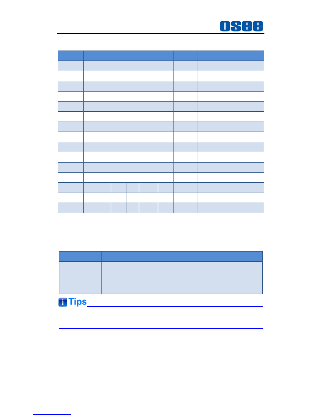
IMP5212 Features
24
Table 4.2-1 The Relationship of DVI-M Pins and Channel Values
Pin No.
Channel Value
Pin No.
Channel Value
Pin1
TMDS DATA 2-
Pin13
NOT USED
Pin2
TMDS DATA 2+
Pin14
+5V POWER
Pin3
TMDS 2/4 SHIELD
Pin15
GND
Pin4
NOT USED
Pin16
HOT PLUG DETECT
Pin5
NOT USED
Pin17
TMDS DATA 0-
Pin6
DDC CLOCK
Pin18
TMDS DATA 0+
Pin7
DDC DATA
Pin19
TMDS 0/5 SHIELD
Pin8
ANALOG VERT.SYNC
Pin20
NOT USED
Pin9
TMDS DATA 1-
Pin21
NOT USED
Pin10
TMDS DATA 1+
Pin22
TMDS CLOCK SHIELD
Pin11
TMDS 1/3 SHIELD
Pin23
TMDS CLOCK+
Pin12
NOT USED
Pin24
TMDS CLOCK-
C1
ANALOG
R Y / Pr
C4
ANALOG HORZ SYNC
C2
ANALOG
G / CVBS Y
C5
ANALOG GROUND
C3
ANALOG
B C / Pb
The DVI IN input supports the following resolutions, as shown in Table 4-2:
Table 4-2 The Resolutions of the DVI Interfaces
Name
Resolutions
Input formats
640X480, 800X600, 1024X768, 1280X720, 1280X768,
1280X800, 1280X1024, 1360X768, 1366X768, 1400X1050,
1440X900, 1600X1200, 1680X1050, 1920X1080,
It supports up to 13 input modules in one IMP5212 frame.
Input Adaptor
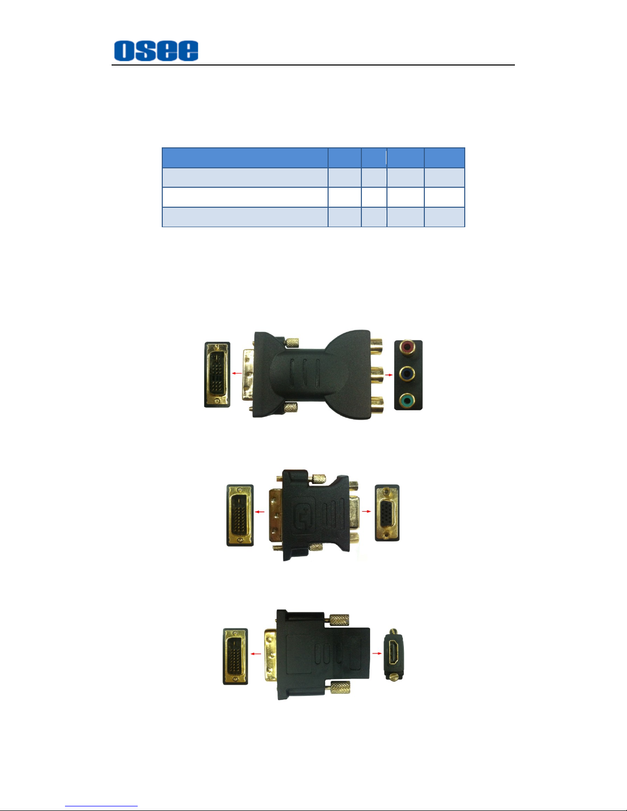
There are three kinds of input adaptor for the various input signals:
Page 31
IMP5212 Features
25
DVI-M-3 Adaptor (YPbPr、S-Video、CVBS): the image for this
adaptor is as shown in Figure 4.2-8. Make sure the composited
Video interface is corresponding to the input signal type, the
relationship is as shown in the table below:
Interface Color\Signal Type
RGB
Y/C
CVBS
YPbPr
Red
R Y /
Pr
Green
G / CVBS
Y
Blue
B C /
Pb
DVI-M-V Adaptor (VGA): the image for this adaptor is as shown in
Figure 4.2-9.
DVI-M-H Adaptor (HDMI): the image for this adaptor is as shown in
Figure 4.2-10.
Figure 4.2-8 DVI-M-3 Adaptor
Figure 4.2-9 DVI-M-V Adaptor
Figure 4.2-10 DVI-M-H Adaptor
Page 32
IMP5212 Features
26
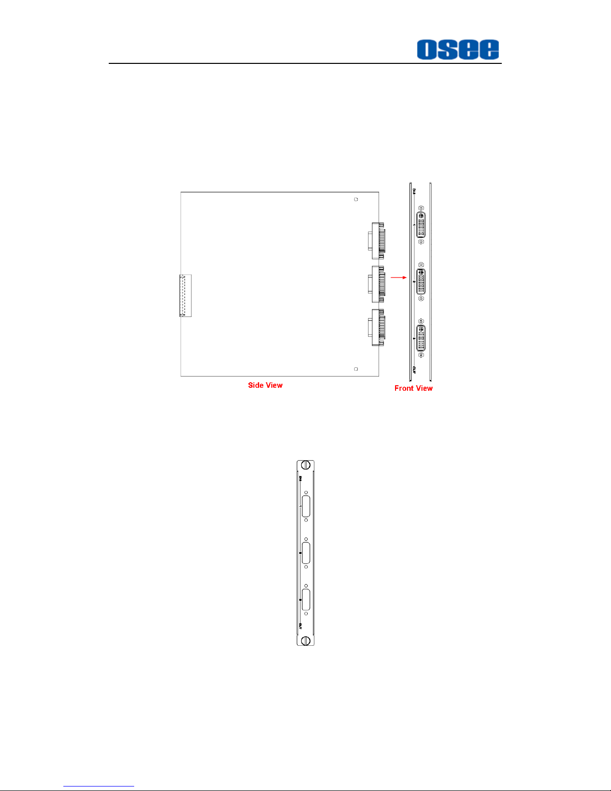
4.2.3 Output Module
IMP5212 provides an output module. Each output module supports three
DVI outputs. The output module is cooperated with its matched output
module panel, as shown in Figure 4.2-11:
Output Module
Figure 4.2-11 Output Module (Side View)
Panel for Output Module
Figure 4.2-12 Panel for Output Module (Front View)
After insert the output module into the corresponding slot, and put the
panel onto the interfaces of the output module, fasten the screws to fix the
Page 33
IMP5212 Features
27
module and its panel.
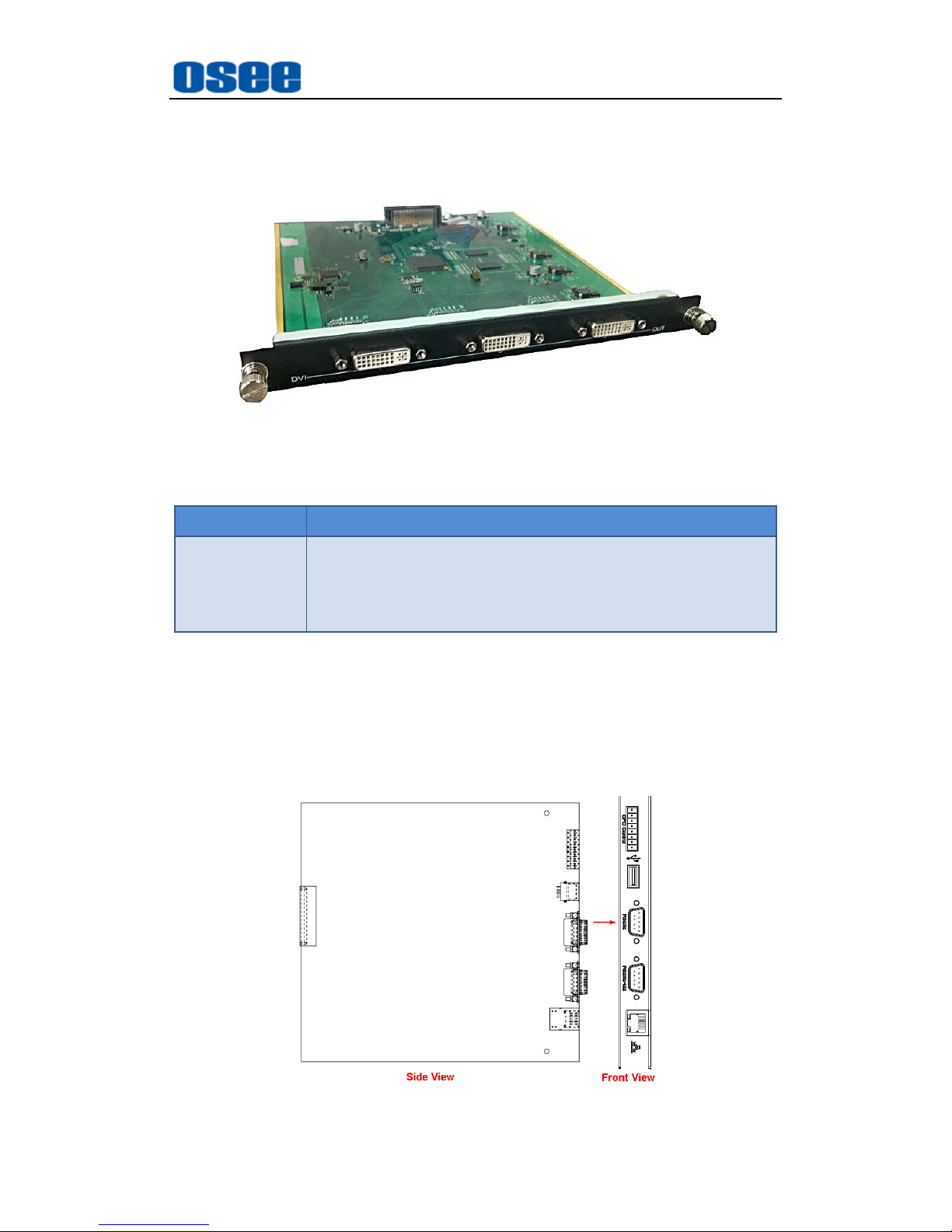
The output module provides 3 channels of DVI OUT outputs, with DVI-D
interface, the physical diagram is shown in Figure 4.2-13:
Figure 4.2-13 Image for Output Module
Table 4-3 The Resolutions of the DVI Interfaces
Name
Resolutions
Output formats
640X480, 800X600, 1024X768, 1280X720, 1280X768,
1280X1024, 1920X1080
4.2.4 Control Module
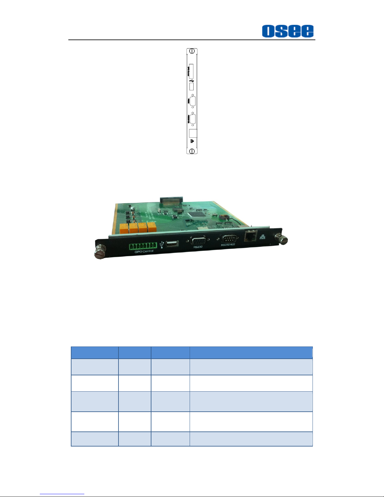
The control module is also a combination of a control module (board) and
its panel, as shown in Figure 4.2-14 and Figure 4.2-15:
Control Module
Figure 4.2-14 Control Module (Side View)
Page 34
IMP5212 Features
28
Figure 4.2-15 Panel for Control Module (Front View)
The physical diagram for the Control Module is as shown in Figure 4.2-16:
Figure 4.2-16 Image for Control Module
1. Connectors in Control Module
The labels of the interfaces on the control module are as shown in Table
4.2-4:
Table 4.2-4 The Interfaces of control Module
Name
Number
Connector
Description
GPO Control
1
8pin
GPO Control Interface
USB
1
USB
USB Interface
RS232
1
DB9
RS232 communication Interface, to
connect the external device
RS232/422
1
DB9
RS232/422 communication Interface,
to connect the control computer
ETHERNET
1
RJ45
10/100 Base-T Interface
Page 35
IMP5212 Features
29
2. Interfaces Introduction
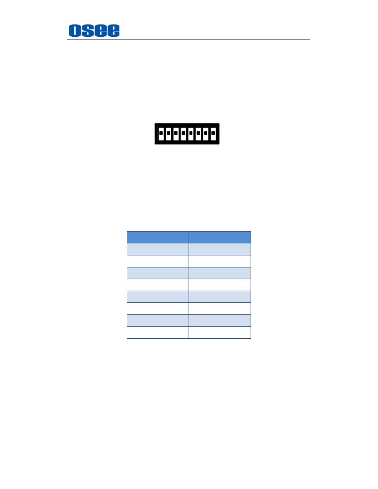
(1) GPO(8PIN)
It provides one GPO interface, and the connector is an 8 pins
element. The pins are numbered from left to right, as shown in
Figure 4.2-17. They are corresponding to four pairs of relay witches
for remote control.
12345678
Figure 4.2-17 The Pins Sequence of GPO Connector
The relationship of the pins of GPO connector and its channel
value is shown in Table 4.2-5:
Table 4.2-5 The Relationship of GPO Pins(8Pin) and Channel Values
Pin No. Channel Value
Pin1 OUT3_A
Pin2 OUT3_B
Pin3
OUT2_A
Pin4
OUT2_B
Pin5
OUT1_A
Pin6
OUT1_B
Pin7
OUT0_A
Pin8
OUT0_B
(2) USB
It provides one USB interface to update the program of this device.
(3) RS232 (DB9)
It provides one RS232-422 interface, the connector is DB9 female.
Use this interface to connect with other video devices to implement
router control, and you should set the communication parameters
in the OSEE Video Wall System software, click set button "Device
Management" "Serial Port", the window is as shown in Figure
Page 36
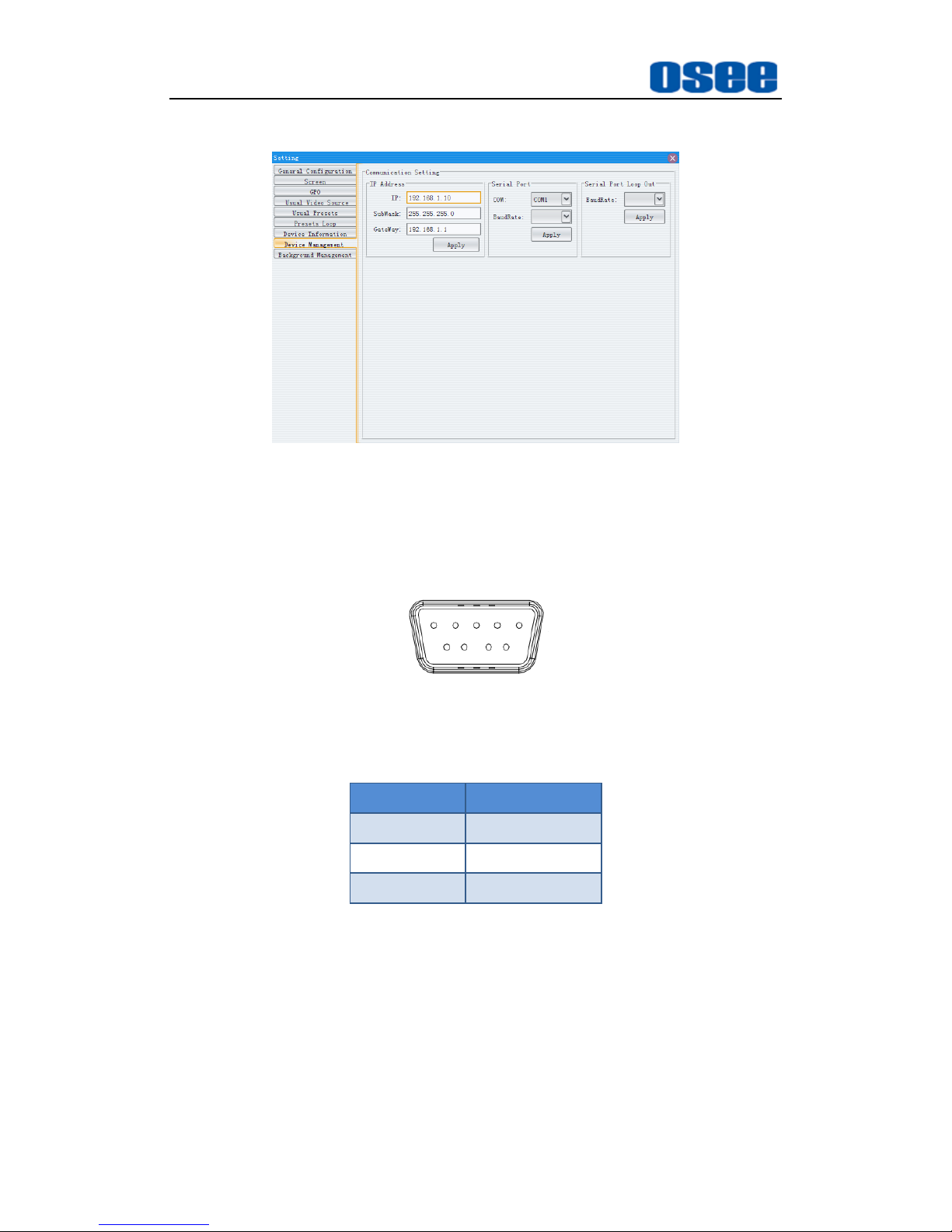
IMP5212 Features
30
4.2-18:
Figure 4.2-18 Setting Values for RS232 Parameters
The relationship of the pins of RS232 connector and its channel
value is shown in Table 4.2-6.
15
69
RS232
Figure 4.2-19 The Pins Sequence of RS232 Connector
Table 4.2-6 The Relationship of RS232 and Channel Values
Pin No.
Channel Value
Pin2
Rx
Pin3
Tx
Pin5
GND
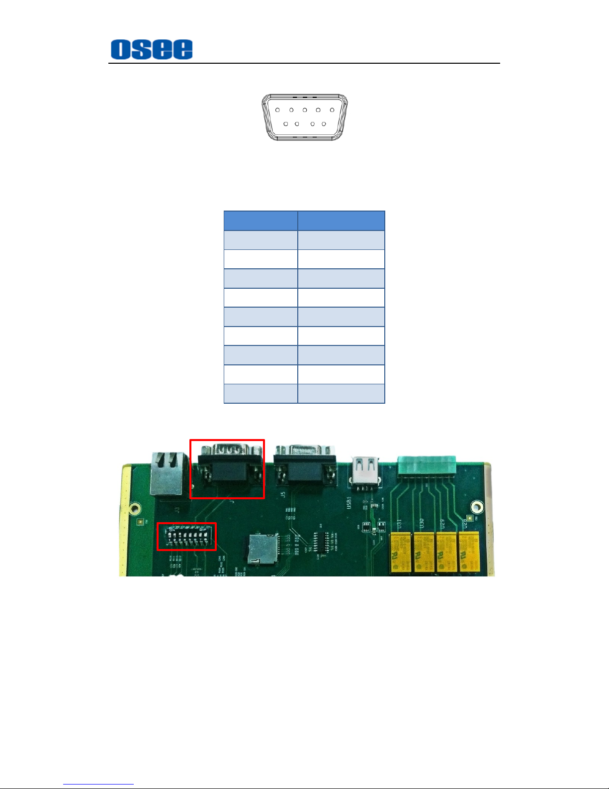
(4) RS232-422 (DB9)
It provides one RS232-422 interface, the connector is DB9 male.
This interface is used to connect and communicate with the remote
control computer.
The relationship of the pins of RS232-422 connector and its
channel value is shown in Table 4.2-7.
Page 37
IMP5212 Features
31
51
96
RS232-422
Figure 4.2-20 The Pins Sequence of RS232-422 Connector
Table 4.2-7 The Relationship of RS232-422 and Channel Values
Pin No.
Channel Value
Pin1
NC
Pin 2
RS422Tx-
Pin 3 RS422Rx+
Pin4 NC
Pin5 GND
Pin6 NC
Pin7 RS422Tx+
Pin8 RS422Rx-
Pin9 NC
The function of the RS232-422 interface is determined by a dip switch on
the control module, as shown in Figure 4.2-21:
Dip Switch
RS232-422
Figure 4.2-21 The Position of the Dip Switch for RS232-422
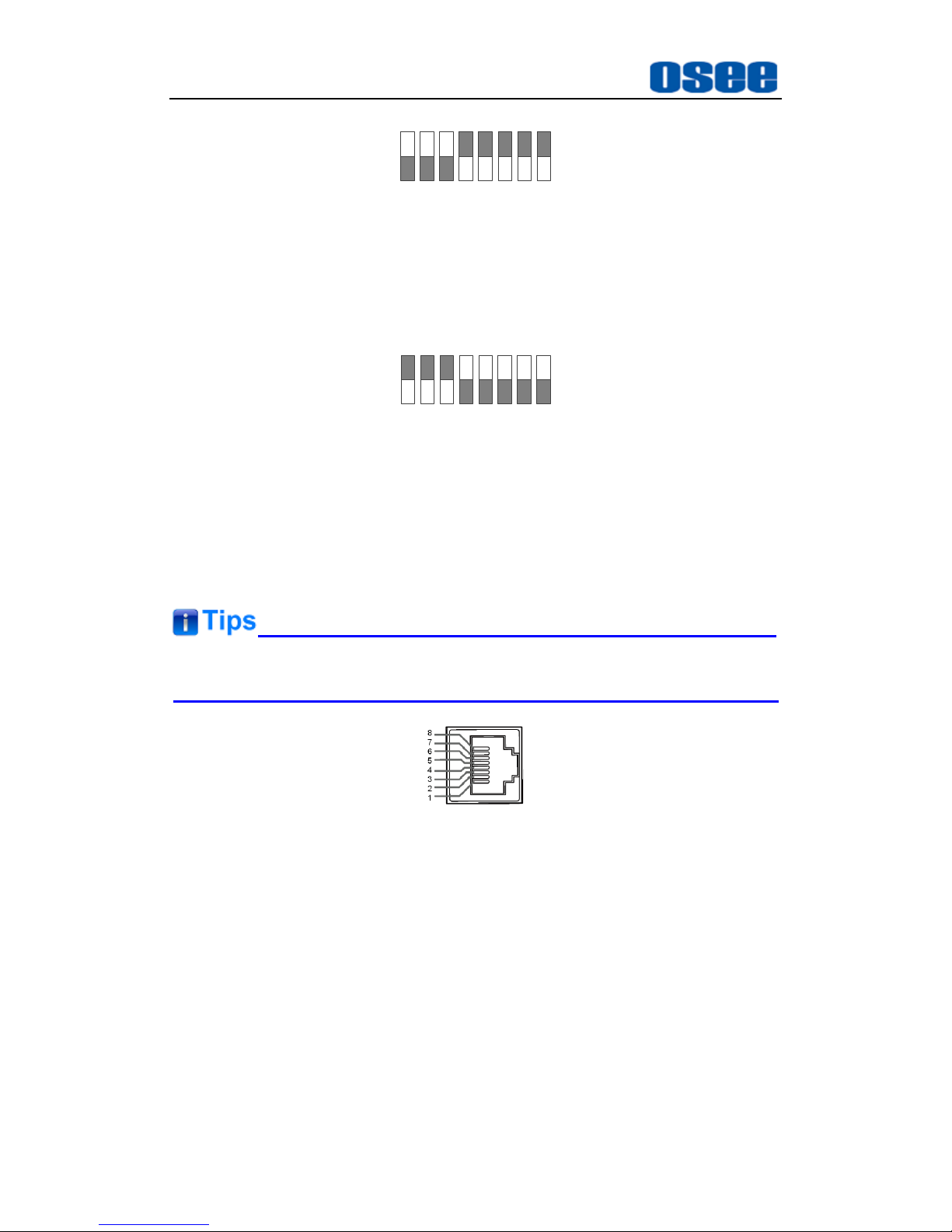
The interface is used as RS232 when the dip switch is set as this: the
former three bits are set to ON and the latter five bits are set to OFF, as
shown in Figure 4.2-22.
Page 38
IMP5212 Features
32
1 2 3 4 5 6 7 8
ON DIP
Figure 4.2-22 The Dip Switch Sequence of RS232
The interface is used as RS422 when the dip switch is set as this: the
former three bits are set to OFF and the latter five bits are set to ON, as
shown in Figure 4.2-23.
1 2 3 4 5 6 7 8
ON DIP
Figure 4.2-23 The Dip Switch Sequence of RS422
(5) ETHERNET (RJ-45)
It provides one 10/100M Ethernet interface which is used to
connect with a computer to access the network control page or run
the device control tool to modify the network settings.
The default IP address of IMP5212 is 192.168.1.10.
Figure 4.2-24 The Ethernet Interface
4.3 Device Connection
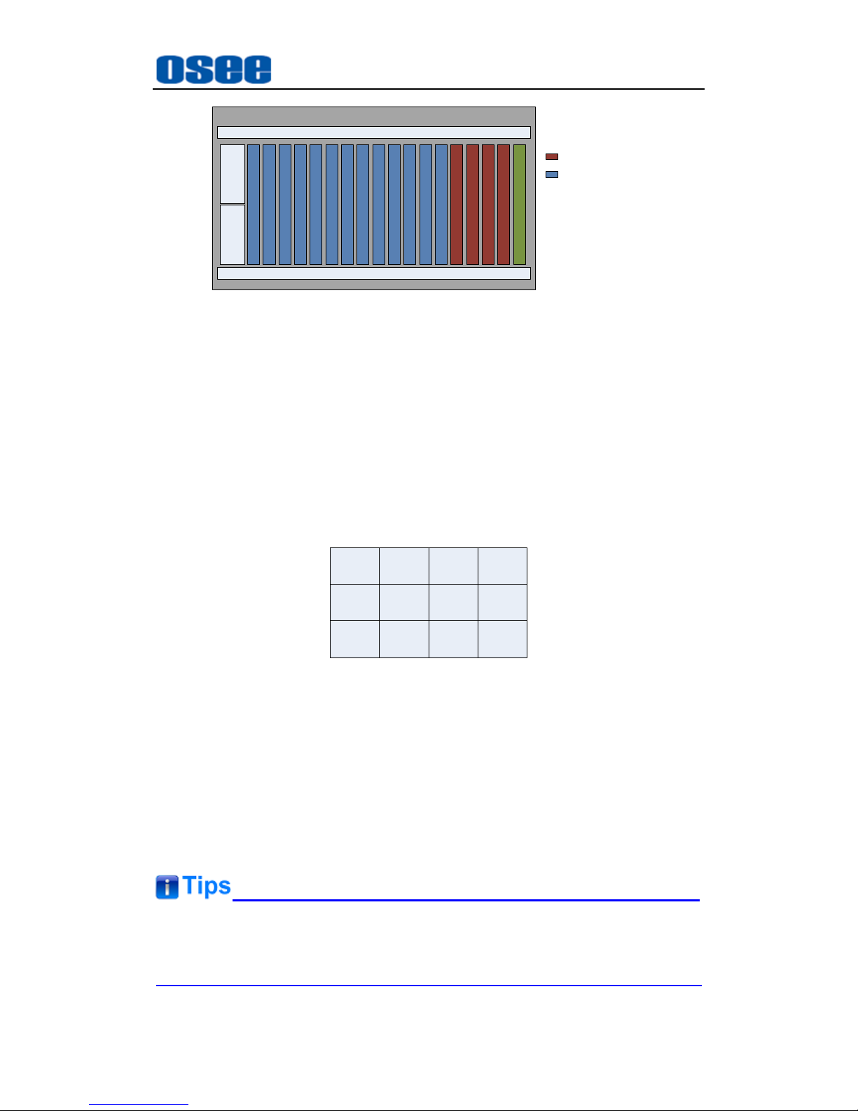
Connect the signal sources with the input interfaces of IMP5212 using cables,
and connect the display screens with the output interfaces of IMP5212 using
cables. The arrangement of the input modules and the output modules fully
loaded are as shown in Figure 4.3-1:
Page 39
IMP5212 Features
33
C
O
N
T
R
O
L
P
O
W
E
R
FAN
FAN
1
2
3
4
5
6
7
8
9
10
11
12
P
O
W
E
R
:OUTPUT
:INPUT
12345678910111213141516171819
20
2122232425
26
Figure 4.3-1 The Arrangement of Input Modules and Output Modules
The rules of the connection sequence between the output interfaces
and display screens:
For the slots of input module and output module in IMP5212 are
changeless, so the priority of the slots must be from the smaller numbered
slot to the bigger slot one by one, and without skip. The arrangement
sequence instruction is: display screens are numbered right to left, top to
bottom corresponding with the number of the output interface.
Example
: there are 12 pieces of screens, the output interfaces and the
screens are shown as in Figure 4.3-2.
1 4 7
2 5 8
3 6 9
10
11
12
Figure 4.3-2 The Arrangement of Display Screens
4.4 Control Access
The IMP5212 is connected to its remote control computer through the Ethernet
interface using the twisted-pair cable. Start up the computer and run the OSEE
Video Wall System software, and the software will load the information of the
video wall processor after setting up the connection.
The Video Wall processor and the remote control computer must be at the
same network segment.
Page 40
IMP5212 Features
34
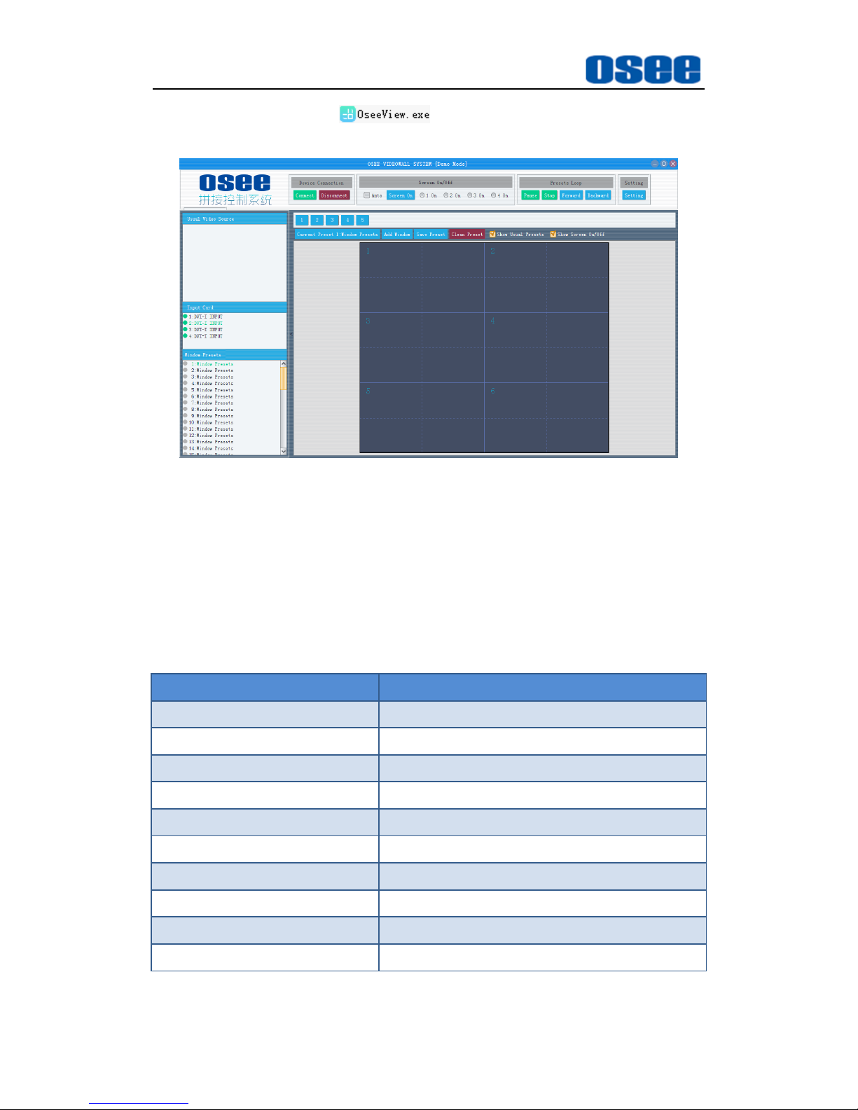
Double click the program in the installation folder of the OSEE
video wall system software, the software interface is shown in Figure 4.4-1:
Figure 4.4-1 The Interface of OSEE Video Wall System Software
Refer to "The Manual for the OSEE Video Wall System" for details.
4.5 Control Instruction Set
1. Set the Screen ON/OFF Instructions
Set the manual/automatic GPO* ON/OFF instructions.
Command
Instruction
Manual-GPO1 ON
EB-A5-04-00-98-03-01-01-A5-EB
Manual-GPO1 OFF
EB-A5-04-00-98-03-00-01-A5-EB
Manual-GPO2 ON
EB-A5-04-00-98-05-02-01-A5-EB
Manual-GPO2 OFF
EB-A5-04-00-98-05-00-01-A5-EB
Manual-GPO3 ON
EB-A5-04-00-98-09-04-01-A5-EB
Manual-GPO3 OFF
EB-A5-04-00-98-09-00-01-A5-EB
Manual-GPO4 ON
EB-A5-04-00-98-11-08-01-A5-EB
Manual-GPO4 OFF
EB-A5-04-00-98-11-00-01-A5-EB
Automatic-GPO1~GPO4 ON
EB-A5-04-00-98-1F-0F-00-A5-EB
Automatic-GPO1~GPO4 OFF
EB-A5-04-00-98-1F-00-00-A5-EB
The strike through line in the instructions above is just used to split the
data bits to be easy distinguished, clean it when you input the instructions.
Page 41
IMP5212 Features
35
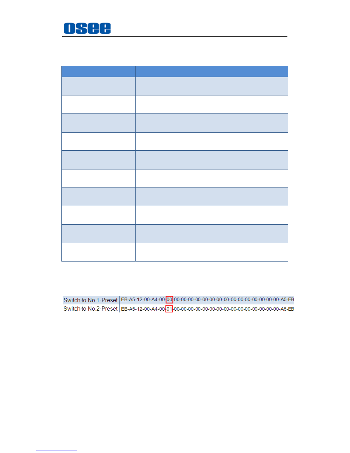
2. Switch Preset Instructions
Use the following instruction to switch to the corresponding preset n.
Command
Instruction
Switch to No.1 Preset
EB-A5-12-00-A4-00-00-00-00-00-00-00-00-00-00-0
0-00-00-00-00-00-00-A5-EB
Switch to No.2 Preset
EB-A5-12-00-A4-00-01-00-00-00-00-00-00-00-00-0
0-00-00-00-00-00-00-A5-EB
Switch to No.3 Preset
EB-A5-12-00-A4-00-02-00-00-00-00-00-00-00-00-0
0-00-00-00-00-00-00-A5-EB
Switch to No.4 Preset
EB-A5-12-00-A4-00-03-00-00-00-00-00-00-00-00-0
0-00-00-00-00-00-00-A5-EB
Switch to No.5 Preset
EB-A5-12-00-A4-00-04-00-00-00-00-00-00-00-00-0
0-00-00-00-00-00-00-A5-EB
Switch to No.6 Preset
EB-A5-12-00-A4-00-05-00-00-00-00-00-00-00-00-0
0-00-00-00-00-00-00-A5-EB
Switch to No.7 Preset
EB-A5-12-00-A4-00-06-00-00-00-00-00-00-00-00-0
0-00-00-00-00-00-00-A5-EB
Switch to No.8 Preset
EB-A5-12-00-A4-00-07-00-00-00-00-00-00-00-00-0
0-00-00-00-00-00-00-A5-EB
Switch to No.9 Preset
EB-A5-12-00-A4-00-08-00-00-00-00-00-00-00-00-0
0-00-00-00-00-00-00-A5-EB
Switch to No.10 Preset
EB-A5-12-00-A4-00-09-00-00-00-00-00-00-00-00-0
0-00-00-00-00-00-00-A5-EB
The data bits of the target preset to be switched to is labeled in red
rectangle as the figure below, for example, 00 represents No.1 preset, and
01 represents No.2 preset, and so on. Make sure you input the right data
for your target preset, and the data should be in hexadecimal format.
Page 42

36
Page 43
Specifications
37
Chapter 5 Specifications
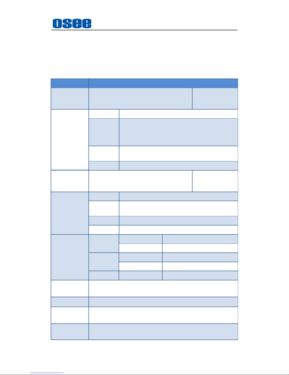
1. Product detailed information
Index
Specification
Input Signals
Up to 26 channels of video input, 2-26 DVI
interface(DVI-M)
1-13 module(each
has 2 input
channels)
Input Module
Formats
CVBS, VGA, DVI, HDMI, YPbPr, S-Video
Resolutions
640X480, 800X600, 1024X768, 1280X720,
1280X768, 1280X800, 1280X1024, 1360X768,
1366X768, 1400X1050, 1440X900, 1600X1200,
1680X1050, 1920X1080
Impedance
75Ω(CVBS/VGA/YPbPr/S-Video),
50Ω(DVI/HDMI)
Connector
DVI-M
Output Signals
3-12 channels of DVI-D signal or HDMI
signal
1-4 module(each
has 3 output
channels)
Output Module
Formats
DVI
Resolutions
640X480, 800X600, 1024X768, 1280X720,
1280X768, 1280X1024, 1920X1080
Impedance
50Ω
Connector
DVI-D
Control
Module
GPO
Contact Rating
1A 30VDC\0.3A 125VAC
Delay time
0~40s
Ethernet
Speed
10/100Base-T
Protocol
TCP/IP
Serial Port
Types
RS232, RS232-422
Operation
Interface
RS422 / remote control through RJ-45 port
Display Units
Up to 12 displays
Control
Software
OSEE Video Wall System
Environment
Temperature: 0~70℃
Humidity: 10%~90% No condensation
Page 44
38
Index
Specification
Weight(fully
loaded)
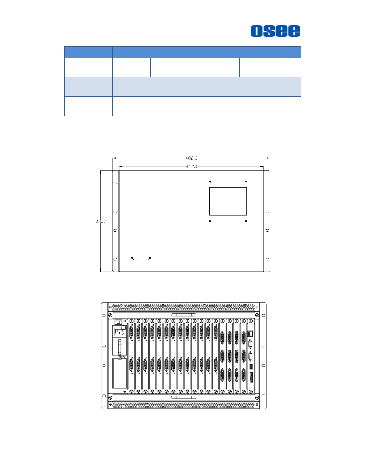
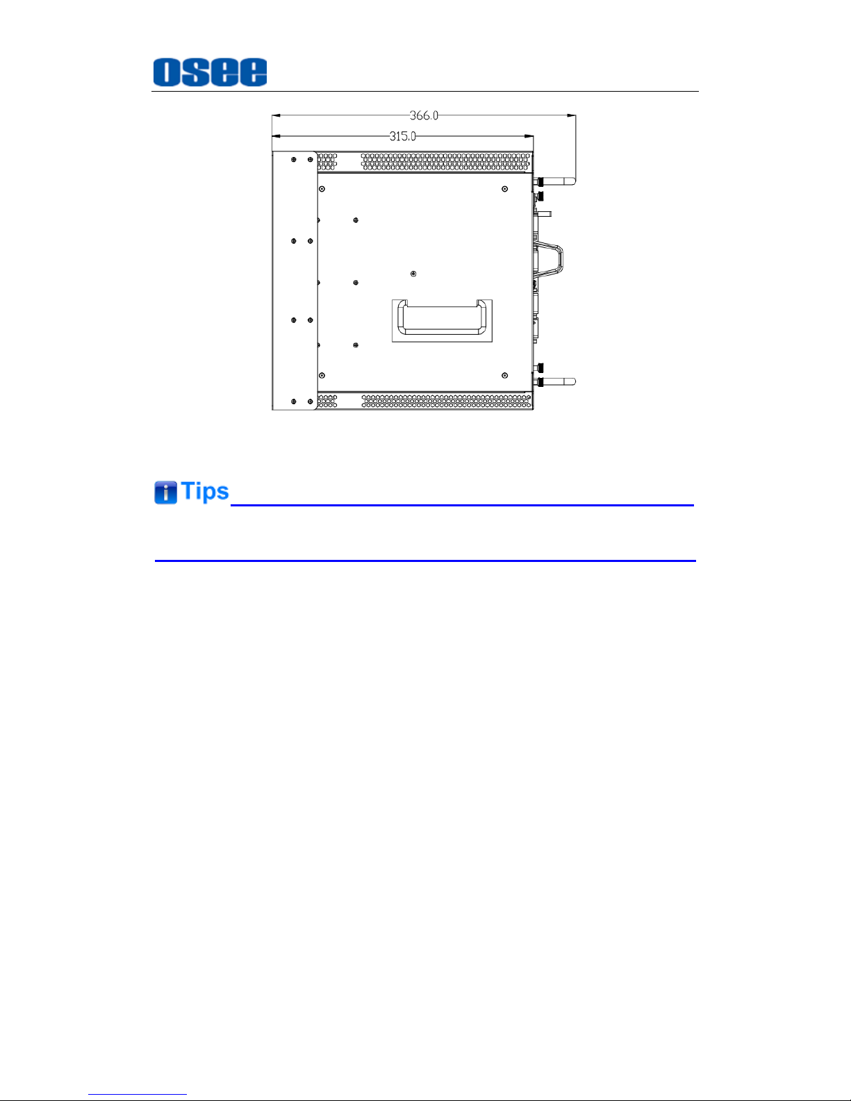
7U, 30kg
442(L)×315(W)×310(H)mm
18 slots
Power
Consumption
300W
Electrical
Characteristics
100-240VAC, 50-60Hz, two redundant power modules
2. Product Outline
The outline of IMP5212 is shown as in the following figures:
Figure 5-1 Front View
Figure 5-2 Back View
Specifications
Page 45
39
Figure 5-3 Side View
Specifications are subject to change without notice.
------------------No Text Below------------------
Specifications
Page 46
FOR MORE INFORMATION PLEASE VISIT: http://www.osee-dig.com/
OSEE TECHNOLOGY CO., LTD.
No.22 Building, No.68 zone, Beiqing Road, Haidian District, Beijing, China
Tel: (+86) 010-62434168, Fax: (+86) 010-62434169
E-mail: [email protected]
 Loading...