

OSEE HDX6811N, HDX6812N, HDX6811N-3G, HDX6812N-3G User Manual

HDX6811N/HDX6812N
High-definition Digital
Audio De-embedder
USER MANUAL

Product Information
Model:
HDX6811N/HDX6812N High-definition Digital Audio De-embedder
Version:
V010001
Release Date:
May 22th, 2012
Company
OSEE TECHNOLOGY CO., LTD.
Contact Information
Address:
No.22 Building, No.68 zone, Beiqing Road, Haidian District,
Beijing, China
Post Code:
100094
Tel:
(+86) 010-62434168
Fax:
(+86) 010-62434169
Web:
http://www.osee-dig.com/
E-mail:
sales@osee-dig.com

About this manual
The manual applies to the following models:
HDX6811N
HDX6811N -3G
HDX6812N
HDX6812N -3G
Any different specifications are detailed in the manual.
Please make sure your device model before you read it.

Content
Chapter 1 Overview .................................................................................... 1
1.1 Introduction ......................................................................................................................... 1
1.2 Feature ................................................................................................................................. 1
1.3 Module Descriptions ........................................................................................................... 2
1.3.1 The Front Part of Module .............................................................................................. 2
1.3.2 Rear panel connector ................................................................................................... 3
1.3.3 The back of HDX6811N/HDX6812N ............................................................................... 4
1.4 Signal Flow ......................................................................................................................... 5
Chapter 2 Installation .................................................................................. 6
2.1 Overview ............................................................................................................................. 6
2.2 Maximum Power Ratings for Frame ................................................................................... 6
2.3 Unpacking the Module ........................................................................................................ 6
2.3.1 Preparing the Product for Installation ............................................................................. 6
2.3.2 Check the Packing List ................................................................................................. 6
2.4 Installing the Module .......................................................................................................... 7
2.5 Making the Connections ..................................................................................................... 8
2.6 Removing the Module ......................................................................................................... 8
Chapter 3 Operation and Control ................................................................ 8
3.1 Switches .............................................................................................................................. 8
3.2 Parameter settings ............................................................................................................... 9
3.2.1 Option Description ........................................................................................................ 9
3.3 LED Indicator ................................................................................................................... 15
3.4 Setting Jumper................................................................................................................... 16
Chapter 4 HDMI Add-on modules ........................................................... 16
4.1 Install ................................................................................................................................. 17
4.2 Description ........................................................................................................................ 17
Chapter 5 Specifications ........................................................................... 17
5.1 SDI digital video input ...................................................................................................... 18
5.2 Digital video output .......................................................................................................... 18
5.3 Digital audio output .......................................................................................................... 18
5.4 HDMI input ....................................................................................................................... 19

HDX6811N/HDX6812N HD Audio De-embedder
User Manual
1
Chapter 1 Overview
1.1 Introduction
The HDX6811N/HDX6812N High-definition Digital Audio De-embedder modules can be
installed in 6800N series frame.
HDX6811N/HDX6812N modules provide 1 channel adaptive 3G/HD/SD-SDI video input or 1
channel HDMI input which supports HDCP, 1 channel digital audio reference signal input.
They support 3 channels 3G/HD/SD-SDI video output and 1 channel HDMI output for monitoring.
And 4 pairs of AES/EBU balanced or unbalanced outputs are supported.
The user can choose any channel out of four embedded audio groups as audio output, or choose
the synthesized audio as output signal. The modules support 8-channel audio meter for monitoring
the four pairs of AES/EBU output.
Each module has its own distinct feature as follows:
The HDX6811N has unbalanced AES output, and the HDX6812N has balanced AES output.
HDX6811N/ HDX6812N supports HD/SD-SDI video input, but if the users use the the 3G
authorization code to upgrade the module through the WEB into HDX6811N-3G/ HDX6812N-3G,
the modules can also support 3G video signal format.
Note: The 3G high-definition video signal authorization code is optional.
Each module has its own features stated as Tab. 1-1:
Table 1-1 Input and output
Module Input Output
HDX6811N
1 channel adaptive
3G/HD/SD-SDI video
input
1 channel unbalanced
DARS input
2-channel 3G/HD/SD-SDI
output with reclocking
1 channel optional SDI output
1 channel HDMI output for
monitoring
4 pairs of unbalanced AES
audio output
HDX6812N
1 channel adaptive
3G/HD/SD-SDI video
input
1 channel
unbalanced/balanced
DARS input
1 channel HDMI input
3-channel 3G/HD/SD-SDI
output with reclocking
1 channel HDMI output for
monitoring
4 pairs of balanced AES
audio output
1.2 Feature
The HDX6811N/HDX6812N offers the following features:
De-embedding audio from 3G/HD/SD-SDI input signal, supporting 4 pairs (8
channels)of AES/EBU outputs
De-embedding HD, 3G, and other various video formats
SDI output with equalization and reclocking

HDX6811N/HDX6812N HD Audio De-embedder
User Manual
2
One channel HDMI output monitoring
A variety of available signal sources for each audio output
Video input auto-detect and input status feedback
Support 20-bit and 24-bit audio processing
Support 8-channel audio metering display
Generate Text signal at fixed frequency rate
Support maximum 2.7 seconds audio delay, invert and mute
Support the audio gain adjust, inverted, silencers, exchange processing
EDH /CRC error detection tracking and re-insertion
Built-in video detection signal generator, and built-in audio test signal
Video loss, freeze frame, black field detection
Provide network control functions, for the local and remote set of modules
FCC Caution:
Any Changes or modifications not expressly approved by the party responsible for compliance
could void the user's authority to operate the equipment.
This device complies with part 15 of the FCC Rules.
Operation is subject to the following two conditions: (1) This device may not cause harmful
interference, and (2) this device must accept any interference received, including interference that
may cause undesired operation.
Note: This equipment has been tested and found to comply with the limits for a Class B digital
device, pursuant to part 15 of the FCC Rules. These limits are designed to provide reasonable
protection against harmful interference in a residential installation. This equipment generates uses
and can radiate radio frequency energy and, if not installed and used in accordance with the
instructions, may cause harmful interference to radio communications. However, there is no
guarantee that interference will not occur in a particular installation. If this equipment does cause
harmful interference to radio or television reception, which can be determined by turning the
equipment off and on, the user is encouraged to try to correct the interference by one or more of
the following measures:
Reorient or relocate the receiving antenna.
Increase the separation between the equipment and receiver.
Connect the equipment into an outlet on a circuit different from that to which the receiver is
connected.
Consult the dealer or an experienced radio/TV technician for help.
1.3 Module Descriptions
1.3.1 The Front Part of Module
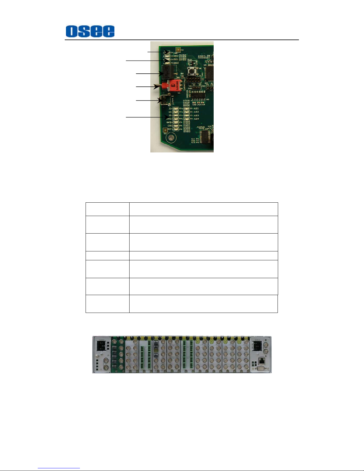
Figure 1-1 shows the control switch and LED indicator in front of the module
HDX6811N/HDX6812N.
HDX6811N/HDX6812N HD Audio De-embedder
User Manual
3
Fig. 1-1 The control switch and LED indicator of HDX6811N/HDX6812N
Table 1-2 describes the control switch and status LED. About the detailed instructions, refer to
Chapter 3: Operation and Control.
Table 1-2 the control switch and LED indicator
Function Description
Module status
LED
Used to indicate the working status of the module. Refer to
Chapter 3 LED instructions for more information.
BANK LED
Display the module BANK choice, for more detail
information refer to Table 3-7.
SW1 Used to select various settings and parameters.
SW2
Through the switch up (UP) or down (DOWN) to tog gle to
set various control parameters.
SW3 (Reserved)
Status LED
Shows some basic information of the module, for more
detail information refer to Table 3-7.
1.3.2 Rear panel connector
Fig. 1-2 Rear panel connector
Module status LED Indicator
SW1
SW2
SW3
Status LED Indicator
Bank LED Indicator
 Loading...