

Page 1
HCM-700
ON CAMERA Monitor
User Manual
Page 2

Page 3

Model:
HCM-700 ON CAMERA Monitor
Version:
V010002
Release Date:
May 18th, 2018
Address:
No.22 Building, No.68 zone, Beiqing Road, Haidian District,
Beijing, China
Post Code:
100094
Tel:
(+86) 010-62434168
Fax:
(+86) 010-62434169
Web:
http://www.osee-dig.com.cn/
E-mail:
Address:
43218 Christy Street, Fremont, CA
Post Code:
94538
Tel:
(+1)510-966-4499
Web:
www.oseedirect.com / www.oseeamericas.com
E-mail:
Product Information
Company
Contact Information
OSEE TECHNOLOGY LTD.
OSEE AMERICAS, LTD.
OSEE TECHNOLOGY LTD.
Page 4
About this manual
Important
The following symbols are used in this manual:
The further information or know-how for described subjects above which
helps user to understand them better.
The safety matters or operations that user must pay attention to when
using this product.
Contents
The user manual applies to the following device types:
HCM-700
The images and descriptions of HCM-700 are adopted as examples in the
following document.
Before reading the manual, please confirm the device type.
Page 5
Contents
Contents .......................................................................................................... I
Chapter 1 Safety ............................................................................................. 1
Chapter 2 Unpack and Installation ............................................................... 5
Chapter 3 Locations and Function of Parts and Control ............................ 7
3.1
Parts and Functions ............................................................................ 7
3.2
Buttons and Functions ....................................................................... 9
3.3
Operations ........................................................................................... 9
3.4
ZOOM ................................................................................................. 13
3.5
Supported Signal Format ................................................................. 16
Chapter 4 Monitor Settings ......................................................................... 17
4.1
Menu Operations ............................................................................... 18
4.2
Monitor Menu ..................................................................................... 19
4.2.1
INPUT and OUPUT ........................................................................ 19
4.2.2
Controls .......................................................................................... 20
4.2.3
User ................................................................................................ 24
4.2.4
System ............................................................................................ 28
Chapter 5 Scenes and Tools ....................................................................... 35
5.1
Scenes Tools Settings ...................................................................... 35
5.1.1
Frame Tools ................................................................................... 36
5.1.2
Expose Tools .................................................................................. 39
5.1.3
Focus Tools .................................................................................... 46
5.1.4
Look Tools ...................................................................................... 48
5.1.5
Scale Tools ..................................................................................... 51
5.2
Tools Operations ............................................................................... 52
5.2.1
Add a Scene ................................................................................... 53
5.2.2
Delete a Scene ............................................................................... 53
5.2.3
Add a Tool ...................................................................................... 54
5.2.4
Load/Close Tool Bar ....................................................................... 55
5.2.5
Open/Close a Tool .......................................................................... 57
5.2.6
Tool Settings ................................................................................... 57
5.2.7
Delete a Tool .................................................................................. 59
Chapter 6 Specifications ............................................................................. 61
6.1
Product detailed information ........................................................... 61
I
Page 6

6.2
Optional Accessories ........................................................................ 63
6.3
Dimensions ........................................................................................ 66
II
Page 7

Safety
Chapter 1 Safety
FCC Caution:
Any Changes or modifications not expressly approved by the party responsible for
compliance could void the user's authority to operate the equipment.
This device complies with part 15 of the FCC Rules.
Operation is subject to the following two conditions: (1) This device may not cause
harmful interference, and (2) this device must accept any interference received,
including interference that may cause undesired operation.
Note: This equipment has been tested and found to comply with the limits for a Class
B digital device, pursuant to part 15 of the FCC Rules. These limits are designed to
provide reasonable protection against harmful interference in a residential installation.
This equipment generates uses and can radiate radio frequency energy and, if not
installed and used in accordance with the instructions, may cause harmful
interference to radio communications. However, there is no guarantee that
interference will not occur in a particular installation. If this equipment does cause
harmful interference to radio or television reception, which can be determined by
turning the equipment off and on, the user is encouraged to try to correct the
interference by one or more of the following measures:
Reorient or relocate the receiving antenna.
Increase the separation between the equipment and receiver.
Connect the equipment into an outlet on a circuit different from that to which the
receiver is connected.
Consult the dealer or an experienced radio/TV technician for help.
1
Page 8

Safety
Warnings:
Read, keep and follow all of these instructions for your safety. Heed all warnings.
Device
Install in accordance with the manufacturer's instructions.
Do not beat with a hard object or scratch the LCD display.
Do not make the freeze picture displaying on the screen time too long,
otherwise, it will leave the afterimage on the screen.
If the brightness is adjusted to the minimum, then it might be hard to see the
display screen.
Refer all servicing to qualified service personnel. Servicing is required if any of
the following occurs:
The unit has been exposed to rain or moisture.
Liquid had been spilled or objects have fallen onto the unit.
The unit has been damaged in any way, such as when the power-supply
cord or plug is damaged.
The unit does not operate normally, or has been dropped.
Clean only with dry cloth.
Do not block any ventilation openings. Leave enough space around the unit
for ventilation.
Do not use this unit near water.
Do not use this unit near any heat sources such as radiators, heat registers,
stoves, or other apparatus (including amplifiers) that product heat.
A nameplate indicating operating voltage, etc., is located on the rear panel.
The socket-outlet shall be installed near the equipment and shall be easily
accessible.
To reduce the risk of fire or electric shock, do not expose the unit to rain or
moisture.
To avoid electrical shock, do not open the cabinet. Refer all servicing to
qualified service personnel.
If the product needs replacement parts, make sure that the service person use
replacement parts specified by the manufacture, or those with the same
characteristics and performance as the original parts. Use of unauthorized
parts can result in fire, electric shock and/or other damage.
2
Page 9
Safety
The panel used in this produce is made of glass. Therefore, it can break when
it is dropped or applied with impact. Be careful not to be injured by broken
glass pieces.
Specifications are subject to change without notice.
Do not use attachments or accessories not recommended by the manufacture.
Use of inadequate attachments may result in serious accidents.
Do not overload AC outlet or extension cord. Overloading can cause fire or
serious electric shock.
Do not defeat the safety purpose of the polarized or grounding-type plug.
Do not damage the power cord, place the heavy objects on the power cord,
stretch the power cord, or bend the power cord.
Protect the power cord from being walked on or pinched, particularly at plugs,
convenience receptacles, and the point where they exit from the unit.
If the power cord is damaged, turn off the power immediately. It is dangerous
to use the unit with a damaged power cord. It may cause fire or electric shock.
Unplug this unit during lighting storms or when unused for long periods of
time.
Disconnect the power cord from the AC outlet by grasping the plug, not by
pulling the cord.
Should any solid object or liquid fall into the cabinet, unplug the unit and have
it checked by qualified personnel before operating it any further.
3
Page 10

4
Page 11
Unpack and Installation
No.
Item
Quantity
1
HCM-700
1 2 Adapter
1 3 User Manual
1 4 Warranty Card
1 5 Certificate card
1
Chapter 2 Unpack and Installation
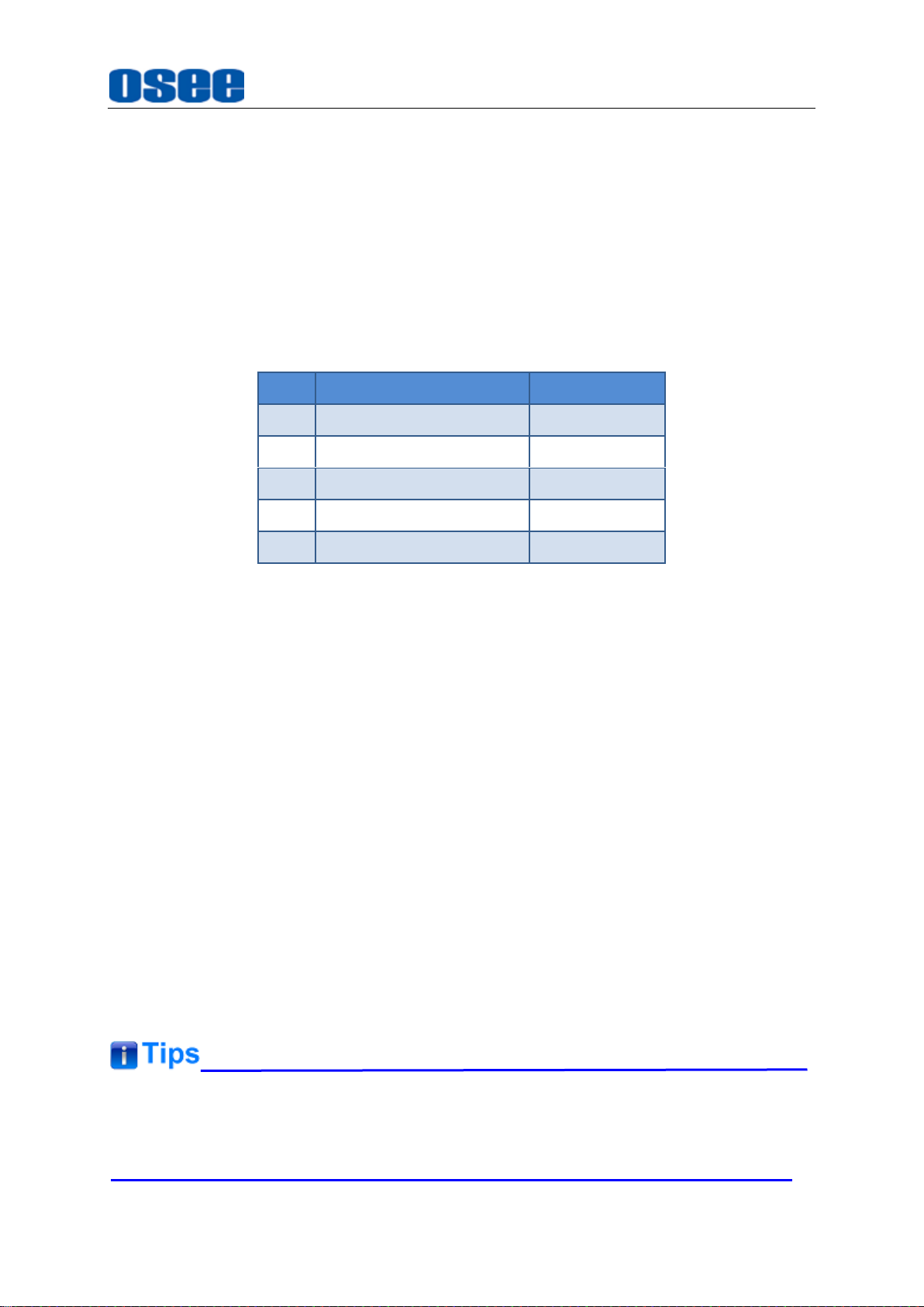
Unpack:
When unpacking the HCM-700 monitor, please verify that none of the components
listed in Table 3.1 are damaged or missing. If there are any components missing,
please contact your distributors or OSEE for it.
Table 3-1 Packing List
Installation:
1. Prepare for installation
Please follow the procedures below before installing HCM-700:
Check the package and equipment for any visible damage that may have
occurred during transit.
Confirm all the items listed on the packing list have been received.
Remove all the packing material including electrostatic-resistant packing.
Retain these packing materials for future use.
2. Connect required cables for signal input and output. For BNC
connections use 75Ω rated connectors.
3. Connect the 11~17VDC power source using the included power supply or
optional battery adapter and D-Tap to Power cable when not using Land
Line power.
4. As a final step, turn on the device by toggling the power switch located on
the rear of the unit near the power jack.
Connect a standard signal line to the corresponding input port.
Please use the power adapter supplied for AC power.
5
Page 12

6
Page 13
Locations and Function of Parts and Control
Chapter 3 Locations and Function
of Parts and Control
3.1 Parts and Functions
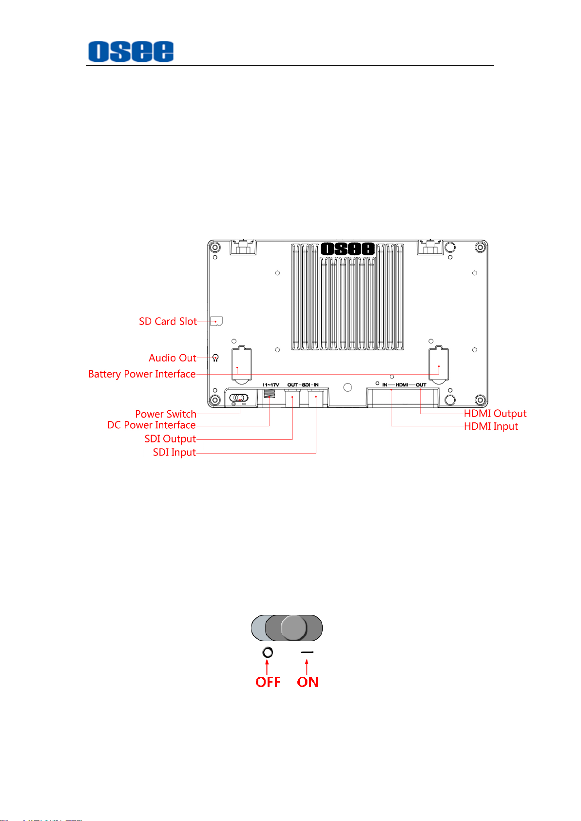
The parts of HCM-700 is shown as below, there are various input and output
interfaces at the rear panel of HCM-700 monitor, as shown in Figure 3.1-1.
Figure 3.1-1 Parts in Rear Panel
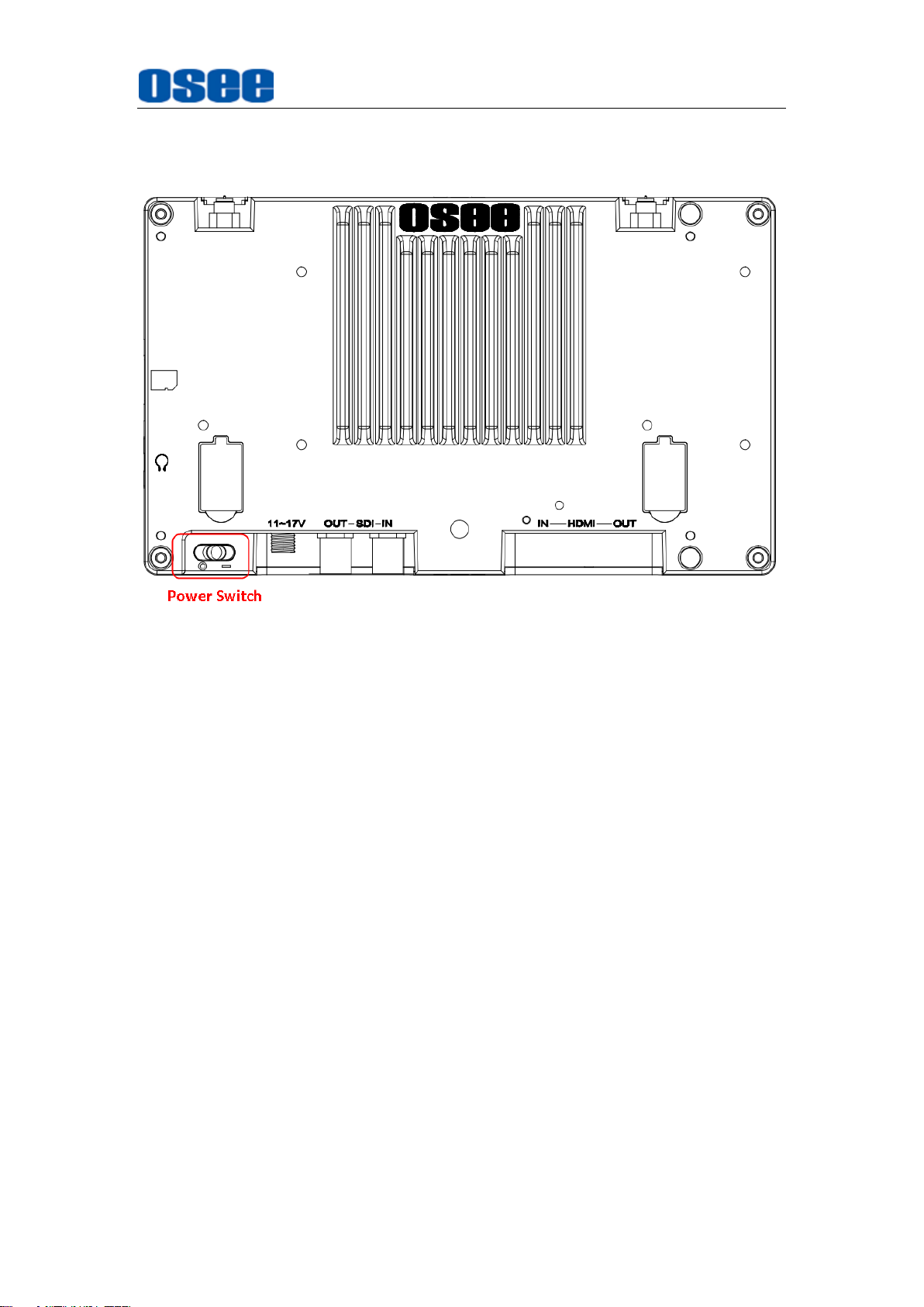
1. Power Switch
Press this part to switch on or switch off the power.
Push the button to the “-” icon to switch on the power, and the backlight
of buttons at the front panel are lit up.
Push the button to the “” icon to switch off the power, and the backlight
of buttons at the front panel are lit off.
7
Page 14

Locations and Function of Parts and Control
It lasts about one minute for starting operation, and please don’t do any
operations during starting the device.
2. Power Input
Plug the power supply to this interface to provide power to the device.
The DC input voltage range is 11 to 17V.
3. Battery Power Input
Two battery input interfaces for battery powered, 6.0~8.4V from Battery
IN. Batteries can be used either in a single or double arrangement.
Figure 3.1-2 Redundant Battery
4. SDI IN (BNC)
One SDI signal input interface, loop out, support multiple format
HD/3G-SDI inputs.
5. SDI OUT(BNC)
One SDI signal output interface.
6. HDMI IN(HDMI)
One HDMI signal input interface, HDMI Type-A connector.
7. HDMI OUT(HDMI)
One HDMI signal output interface.
8. Audio Output
One headphone output jack at Ω position (3.5mm stereo Jack)
8
Page 15
Locations and Function of Parts and Control
9. SD Card Slot
One SD card slot at position, using general SD card to upload or
save LUT files or others.
Only use the adapter and the power cord specified by the manufacture
for your safety!
3.2 Buttons and Functions
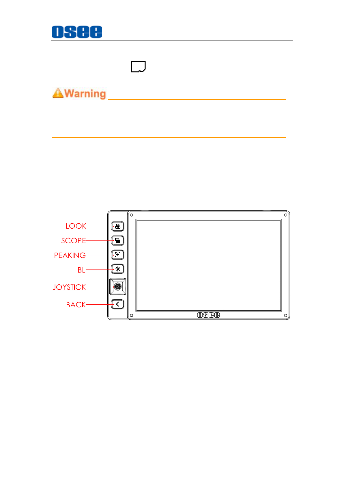
The monitor provides some buttons at the left side of the front panel, as
shown in Figure 3.2-1. They are used for monitor settings, adding tools for
scenes, tools settings, zoom image and so on.
Figure 3.2-1 Buttons in Front Panel
1. Shortcut Buttons: LOOK, SCOPE, PEAKING, BL
2. Joystick: navigate to menu, tool and scene settings
3. Back
3.3 Operations
Shortcut Buttons
9
Page 16
Locations and Function of Parts and Control
The four shortcut buttons are LOOK, SCOPE, PEAKING, BL, achieving swift
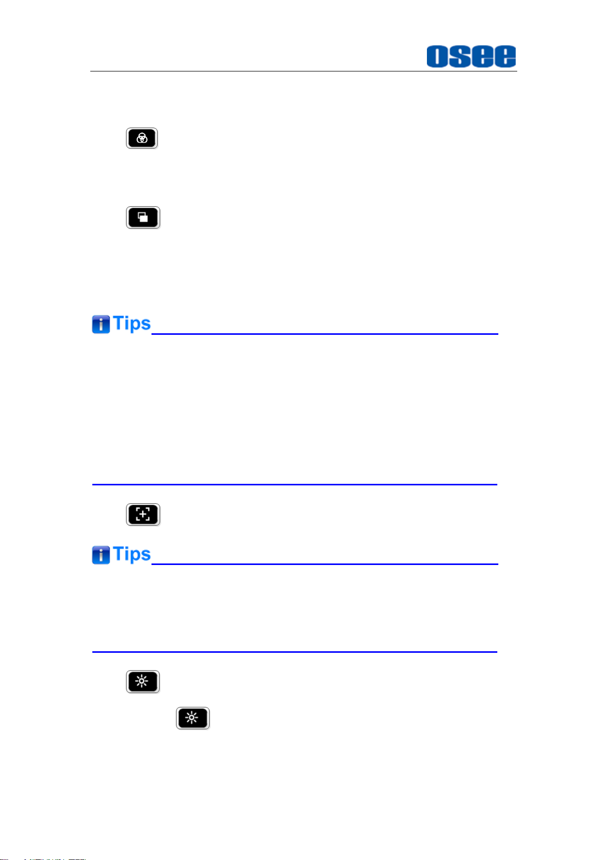
operations for some designated functions. The details are as below:
1. LOOK: load or close a LUT table on scene
Click this button to load or close the first LUT file added in current
scene.
2. SCOPE: load or close the histogram, waveform,
vectorscope or image scale tool on scene
If there are already histogram, waveform, vectorscope or image
scale tool added in the tool bar of the current scene, click this button
to load or close these tools on scene.
For the same type(HISTOGRAM, WAVEFORM, VECTORSCOPE or
IMAGE SCALE) tool, only one tool with the most front position in the tool
bar is valid and can be activated by SCOPE button. For example, there
are two histogram tools and one vectorscope tool added in the tool bar of
a scene, only the first histogram and the vectorscope will be activated by
SCOPE
3. PEAKING: load or close the peaking function on scene
If you had not added the related function to
button.
LOOK, SCOPE
or
PEAKING
button, click the button and there will pop up a prompt “The function not
defined in the Myset!”.
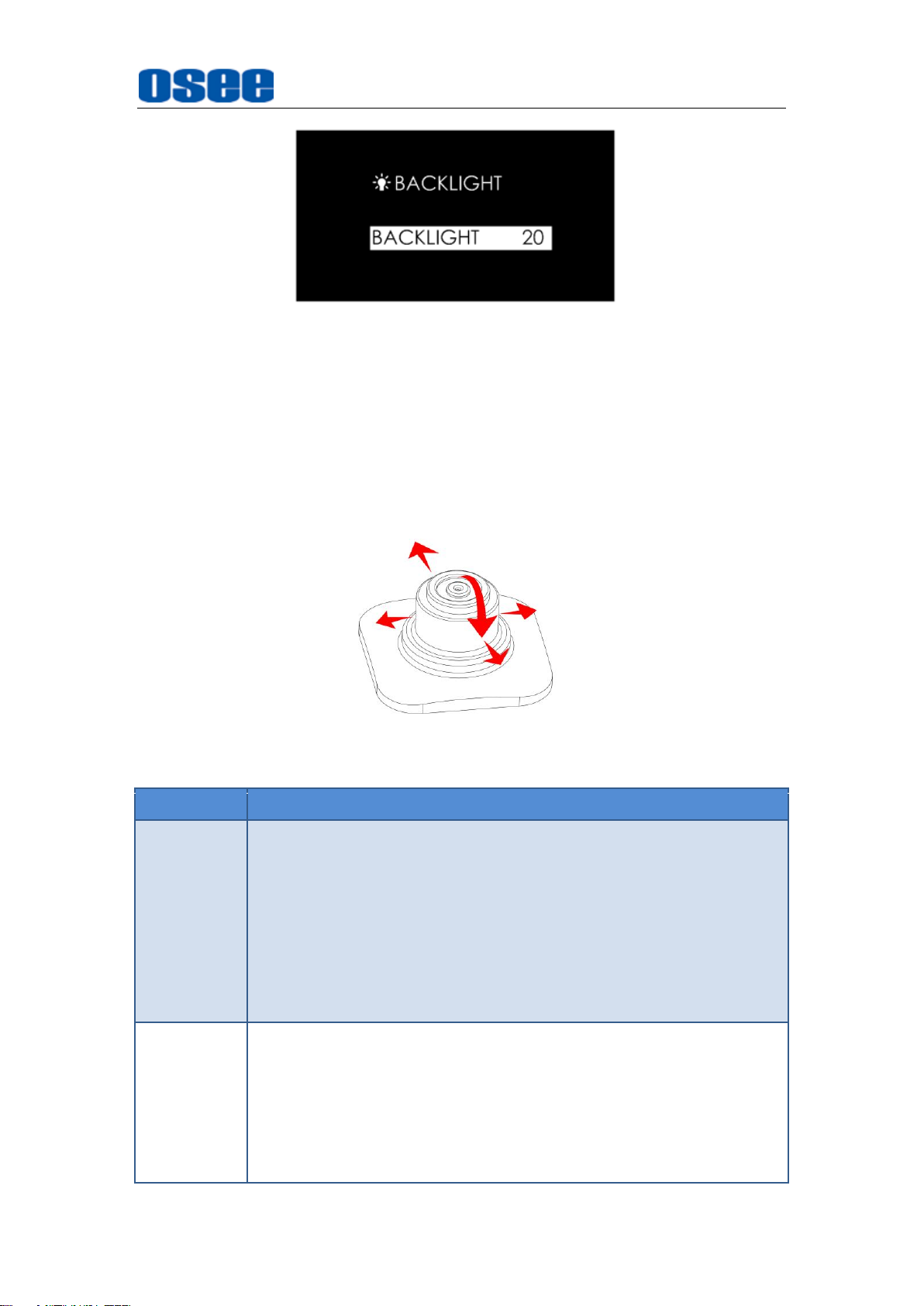
4. Backlight: adjust the backlight
Press the backlight button to adjust the overall light output of the
display, the menu is as shown in Figure 3.3-1. The range of backlight
adjustment is from 0 to 100, and the step is 20.
10
Page 17
Locations and Function of Parts and Control
Direction
Operation
UP
Without any menu, scroll up to enter into ZOOM mode. Keep
scrolling up, and switching among these three modes
FULL2X4X;
In ZOOM 2X or ZOOM 4X editing mode, scroll up the joystick
to move the starting position of the enlarged image;
In monitor settings, scroll down to select the previous item or
increase the item value;
In scene tool menu, scroll down to select the previous item or
increase the item value.
DOWN
Without any menu, scroll down to enter into ZOOM mode.
Keep scrolling up, and switching among these three modes
FULL2X4X;
In ZOOM 2X or ZOOM 4X editing mode, scroll up the joystick
to move the starting position of the enlarged image;
In monitor settings mode, scroll down to select the next item
or decrease the item value;
Figure 3.3-1 Backlight Adjustment Menu
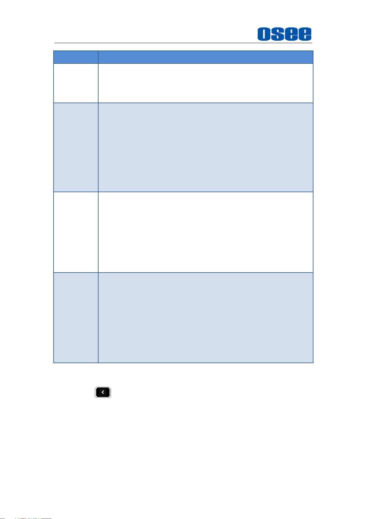
Joystick
Use the joystick as a navigation tool to scroll between scenes pages and set
features. The joystick provides multiple functions with five operation
directions, Up Down, Left, Right, and Straight Down, as shown in Figure
3.3-2.
Figure 3.3-2 Five Operation Directions for Joystick
11
Page 18
Locations and Function of Parts and Control
Direction
Operation
In scene tool menu, scroll down to select the next item or
decrease the item value;;
In scene page, scroll down to select the delete scene
command.
LEFT
Without any menu, scroll leftmost to enter into the monitor
settings menu;
In ZOOM 2X or ZOOM 4X editing mode, scroll left the
joystick to move left the starting position of the enlarged
image;
In monitor settings mode, scroll left to return to the previous
level menu, or decrease the item value;
In a tool bar of a scene, scroll left to return back to the
previous level menu, or the downward adjustment the item
value.
RIGHT
Without any menu, scroll right to enter into a scene or create
a scene mode ;
In ZOOM 2X or ZOOM 4X editing mode, scroll right the
joystick to move right the starting position of the enlarged
image;
In monitor settings menu, scroll the joystick right to enter into
the next level menu, or increase the item value;
In a tool bar of a scene, scroll right to enter into the next level
menu, or the upward adjustment the item value.
STRATIGHT
DOWN
In ZOOM 2X or ZOOM 4X mode, press straight down the
joystick to enter into editing the starting position of the
enlarged image mode; In ZOOM 2X or ZOOM 4X editing
mode, press straight down the joystick to confirm and finish
the adjusting of the starting position of the enlarged image;
In a tool bar of a scene, press straight down the joystick to
在
enable or disable the selected tool;
In monitor settings mode, press straight down the joystick to
enter into the next level menu or confirm the selection of the
last level menu item.
BACK
Back button provides the following functionalities:
Cancel the settings
Return to the previous menu
Quit menu settings
Power
12
Page 19
Locations and Function of Parts and Control
The power switch is on the left corner of the rear panel of HCM-700. Use it to
power the HCM-700 on or off.
Figure 3.3-3 Power Switch
3.4 ZOOM
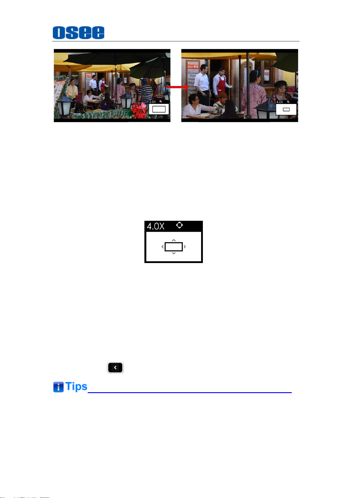
You can get closer view to your image in ZOOM mode. It provides 2X ZOOM
mode and 4X ZOOM mode, that is you can double(2X) or quadruple(4X) the
image, and move the starting position of the enlarged image.
1. ZOOM 2X
Enter Zoom 2X Mode
Scroll right the joystick to enter into a scene, and then scroll up the
joystick to enter into
original one. There will be a Zoom 2X icon at the bottom right of the
screen, as shown in Figure 3.4-1
Zoom 2X
mode, the image is twice as large as the
13
Page 20

Locations and Function of Parts and Control
Figure 3.4-1 Zoom 2X Mode
Zoom 2X Editing Mode
After entering into the Zoom 2X Mode, press straight down the joystick to
move the starting position of the enlarged image.
There will be a Zoom 2X Editing icon at the bottom right of the screen, as
shown in Figure 3.4-2. The small rectangle with four direction arrows in
this icon represents the current full screen image in the monitor, you can
judge where this area is in the original image.
Figure 3.4-2 Zoom 2X Editing Mode
Meanwhile, scroll up, down, left or right the joystick to move the
displayed area to the corresponding direction, then, press straight down
the joystick to confirm and finish the movement and exit the Zoom 2X
Editing mode.
2. ZOOM 4X
Enter Zoom 4X Mode
Scroll up the joystick to show the
Zoom 2X
scrolling the up the joystick to show the
mode, and then keep
Zoom 4X
mode, the image is
four times as large as the original one. There will be a Zoom 4X icon at
the bottom right of the screen, as shown in Figure 3.4-3:
14
Page 21
Locations and Function of Parts and Control
Figure 3.4-3 Zoom 4X Mode
Zoom 4X Editing Mode
After entering into the Zoom 4X Mode, press straight down the joystick to
move the starting position of the enlarged image.
There will be a Zoom 4X Editing icon at the bottom right of the screen, as
shown in Figure 3.4-4. The small rectangle with four direction arrows in
this icon represents the current full screen image in the monitor, you can
judge where this area is in the original image
Figure 3.4-4 Zoom 4X Editing Mode
As the same as Zoom 2X editing mode, scroll up, down, left or right the
joystick to move the displayed area to the corresponding direction, then,
press straight down the joystick to confirm and finish the movement and
exit the Zoom 4X Editing mode.
3. Original Image Mode
Original Image Mode
In Zoom 2X mode or Zoom 4X mode, press straight down the joystick or
press BACK button, it will recover and display the original image.
The scene tools are not editable in ZOOM 2X or ZOOM 4X mode.
In ZOOM 2X mode, you need scroll the joystick 20 times from the origin
of coordinate to the maximum in horizontal direction, and you need scroll
the joystick 10 times from the origin of coordinate to the maximum in
15
Page 22
Locations and Function of Parts and Control
SDI
HDMI
720P24/23.98
720P25
720P30/29.97
720P50
720P60/59.94
1080SF24/23.98
1080I50
1080I60/59.94
1080P24/23.98
1080P25
1080P30/29.97
1080P50
1080P60/59.94
vertical direction.
In ZOOM 4X mode, you need scroll the joystick 40 times from the origin
of coordinate to the maximum in horizontal direction, and you need scroll
the joystick 20 times from the origin of coordinate to the maximum in
vertical direction.
3.5 Supported Signal Format
The supported signal format for this device is as shown in Table 3.5-1:
Table 3.5-1 Supported Signal Format
16
Page 23
Monitor Settings
Chapter 4 Monitor Settings
The chapter describes the structure and functionality of the monitor settings, and
introduces how to modify and customize the monitor settings.
Monitor settings contains the settings on input, output, volume, backlight, image rotate,
anamorphic, output look, DSLR scale, status display menu, LUTs, language, firmware
and so on, as shown in Figure5-1.
Figure 5-1 Monitor Settings Menu
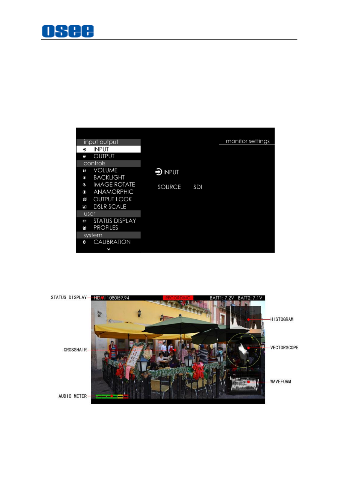
The features on the screen are as shown in Figure 5-2:
Figure 5-2 Tools for HCM-700 Monitor
And there could be multiple accessorial objects on screen, such as status display
information, aspect area, safe area, crosshair, waveform, audio meter, histogram,
17
Page 24

Monitor Settings
focus assist, false color and so on.
Please refer to the corresponding sections for the details in this chapter.
4.1 Menu Operations
Display the Monitor Settings Menu
Scroll leftmost the Joystick to display the monitor settings Menu at the left side of the
screen, as shown in Figure 4.1-1:
Figure 4.1-1 the Structure of the Monitoring Settings Menu
The menu interface is divided into two parts: Level one menu and Level two menu.
Follow the instructions below:
Menu List for Monitor Settings
The level one menu is the main menu list for monitor settings, including input output,
controls, user, and system.
Scroll up and down the Joystick to navigate to the level one menu of the monitor
settings and select a menu item. The selected menu item will be highlighted in a
control icon.
Submenu for Monitor Settings
The details of the selected menu item is displayed at the center right of the screen.
You can check the content of the current menu item.
Scroll straight down the joystick, it will enter into the level two menu page, and the
control icon followed. Then, scroll up or down to select the submenu item, after that,
scroll left or right to switch or adjust the value of the selected submenu item, at last,
Scroll straight down or press BACK button to return to the previous level menu and
confirm the setting.
18
Page 25

Menu
Items
Domain Range
Description
INPUT
SOURCE
SDI/HDMI
Select the input signal source
OUTPUT
SDI
OFF/ON
Enable/Disable the SDI output interface
HDMI
OFF/ON
Enable/Disable the
HDMI output interface
The control icon is displayed as a highlight white rectangle at the background of
the current active item.
Monitor Settings
4.2 Monitor Menu
The following will introduce the contents and functionality of these menu items in
sorts.
4.2.1 INPUT and OUPUT
The INPUT and OUPUT menu items are used to select signal source, and enable or
disable the output interfaces.
Scroll leftmost the joystick to display the monitor settings menu, and the INPUT and
OUPUT menu items are as shown in Figure 4.2-1:
Figure 4.2-1 Input and Output Settings
Table 4.2-1 Description of INPUT and OUTPUT Menu Items
1. Select the input signal source
Select
as
SDI
input outputINPUT
or
HDMI
.
item, scroll left or right to set the input signal source
Figure 4.2-2 Select Input Source
19
Page 26

Monitor Settings
2. Enable an output interface
After setting the input source, it will be output to the two output interfaces:
OUTPUT
SDI OUTPUT
subitem setting of
Enable SDI output interface:
shown in Figure 4.2-3, then you can get a signal source from the SDI
OUTPUT interface.
Disable SDI output interface:
then there will be no signal output from the SDI OUTPUT interface.
The setting for HDMI output interface is as the same as the SDI’s above, no
further description.
and
HDMI OUTPUT
interface or the
input outputOUTPUT
Figure 4.2-3 Enable SDI Output
. Whether you can get the signal source from the
HDMI OUTPUT
set
input outputOUTPUTSDI
set
input outputOUTPUTSDI
interface, it is determined by the
.
as ON, as
as
SDI
OFF
,
For example
disable the HDMI output, then, you can only get the HDMI image from the
OUTPUT
: if the signal source is set as
, but can’t get anything from the
HDMI
HDMI OUTPUT
, enable the SDI output and
SDI
.
4.2.2 Controls
The CONTROLS menu items are used to adjust volume, backlight, rotating image,
and set anamorphic ratio and image size from DSLR device. The menu items are as
shown in Figure 4.2-4:
Figure 4.2-4 Controls Menu
Table 4.2-2 Description of Controls Menu Items
20
Page 27

Menu
Items
Default
Domain Range
Description
VOLUME
VOLUME
50
0~100
Adjust the volume
BACKLIGHT
BACKLIGHT
50
0~100
Adjust the backlight
IMAGE
ROTATE
ROTATE
SCREEN
OFF
OFF/ON
Rotate the image
vertically
ANAMORPHIC
OPTIONS
1X
1X/1.33X/
1.5X/1.66X/
2X/2XMAG
Set the anamorphic ratio
OUTPUT
LOOK
OPTIONS
OFF
OFF/ON
Set whether the output
signal will load a 3D LUT
profile which is the same
as the input signal’s 3D
LUT profile selected in
LOOK menu or not
DSLR SCALE
OPTIONS
NONE
NONE
CANON 5D
MARK II
CANON 7D
Enable the input signal
from a variety of DSLR
cameras to fill the screen
of HCM-700.
This item is particularly
to CANON/NIKON
DSLR.
Monitor Settings
1. Adjust Volume
Select
display the VOULME menu, as shown in Figure 4.2-5. Scroll left to decrease the
volume, or scroll right to increase the volume. Press Back button to return to the
previous level menu.
2. Adjust Backlight
Select
and display the BACKLIGHT menu, as shown in Figure 4.2-6. Scroll left to
decrease, or scroll right to increase the backlight.
controlVOLUME
controlBACKLIGHT
item, scroll straight down to confirm the selection and
Figure 4.2-5 Volume Menu
item, scroll straight down to confirm the selection
21
Page 28

Monitor Settings
ANAMORPHIC
INPUT SIGNAL
INPUT
OUTPUT
1X
1080P/1080I
1920x1080
1920x1080
720P
1280x720
1920x1080
1.33X
1080P/1080I
1920x1080
1920x812
720P
1280x720
1920x812
1.5X
1080P/1080I
1920x1080
1920x720
720P
1280x720
1920x720
1.66X
1080P/1080I
1920x1080
1920x650
720P
1280x720
1920x650
2X
1080P/1080I
1920x1080
1920x540
720P
1280x720
1920x540
2XMAG
1080P/1080I
1290x720
1920x803
720P
860x720
1920x803
Figure 4.2-6 Backlight Menu
3. Set Anamorphic Ratio
This feature enables you to de-squeeze HD-SDI, and 3G-SDI signals coming
from camera utilizing anamorphic lenses that may not have a built-in de-squeeze
feature of their own. This is quite useful in applications, such as outdoor post
production, onset monitoring, real-time de-squeezing, etc.
Select
controlANAMORPHIC
selection and display the
ANAMORPHIC
item, scroll straight down to confirm the
, as shown in Figure 4.2-7scroll left or
right to switch the anamorphic ratio among: 1X, 1.33X, 1.5X, 1.66X, 2X, 2XMAG.
Figure 4.2-7 ANAMORPHIC Menu
The resolution of the input and output are as shown in Table 4.2-3:
Table 4.2-3 Resolution Relationship Between Input and Output
22
Page 29
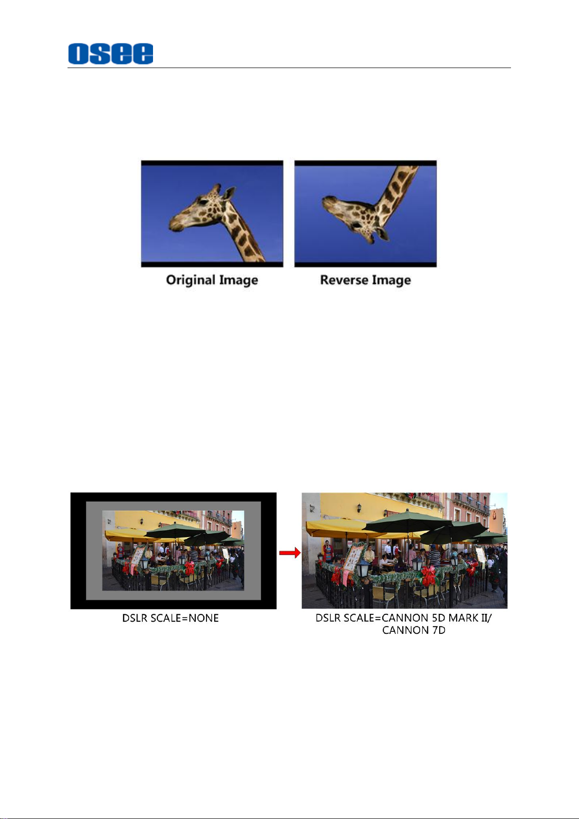
4. Image Rotate
Vertical Rotate
Monitor Settings
Set
controlImage Rotate Rotate Screen
reverse vertically, as shown in Figure 4.2-8:
Figure 4.2-8 Vertical Rotate
5. DSLR SCALE
This function is designed for some DSLR cameras (CANON 5D MARK II,
CANON 7D). The valid area which will fill the screen is controlled by
controlDSLR SCALE
When the input source is coming from CANON 5D MARK II or CANON 7D DSLR
device, but the
function is disable, there will be blank area at the surrounding of the image.
Otherwise, set as the corresponding DSLR model, it will enlarge and display the
image at full screen, removing those useless blank bars, as shown in Figure
4.2-9:
controlDSLR SCALE
item selection.
item is set as
item to be ON, the input image will
NONE
, the
DSLR SCALE
Figure 4.2-9 DSLR SCALE
For different
and output is as shown in the table below:
DSLR SCALE
item value, the resolution comparison of the input
23
Page 30

Monitor Settings
DSLR SCALE Item
INPUT RESOLUTION
OUTPUT RESOLUTION
NONE
1920X1080
1920x1080
CANNON 5D MARK II
(1920X1080)x0.85
1920x1080
CANNON 7D
(1920X1080) x0.85
1920x1080
Menu
Items
Description
STATUS
DISPLAY
OPTIONS
Enable/disable the status bar at
the top of the screen
PROFILES
SAVE PROFILES
TO SD CARD
--
--
Save the profiles data to the
SD card
LOAD PROFILES
FROM SD CARD
--
--
Down load the data from SD
card
4.2.3 User
The User menu items are used to set the status display bar, Fast mode, multiple
images display mode and settings, backlight, auto standby mode, aperture, language
mode, horizontal flip, and uniformity, the menu items are as shown in Figure 4.2-10:
Figure 4.2-10 User Settings Menu
Table 4.2-4 Description of User Menu Items
Default
OFF
1. STATUS BAR
Set
userSTATUS DISPLAY
top of the screen, including these information from left to right: Input source
format, tally indicator and the two battery voltage indications.
Domain
Range
OFF/ON
item to be ON, it will display the Status bar at the
Figure 4.2-11 Status Bar
24
Page 31
INPUT FORMAT
Monitor Settings
The
Signal Format
UNKNOWN
NO SIGNAL
Normal
1080i59.94, etc. when the input is supported by the monitor.
TALLY Indicator
: Tally is on;
: Tally is off.
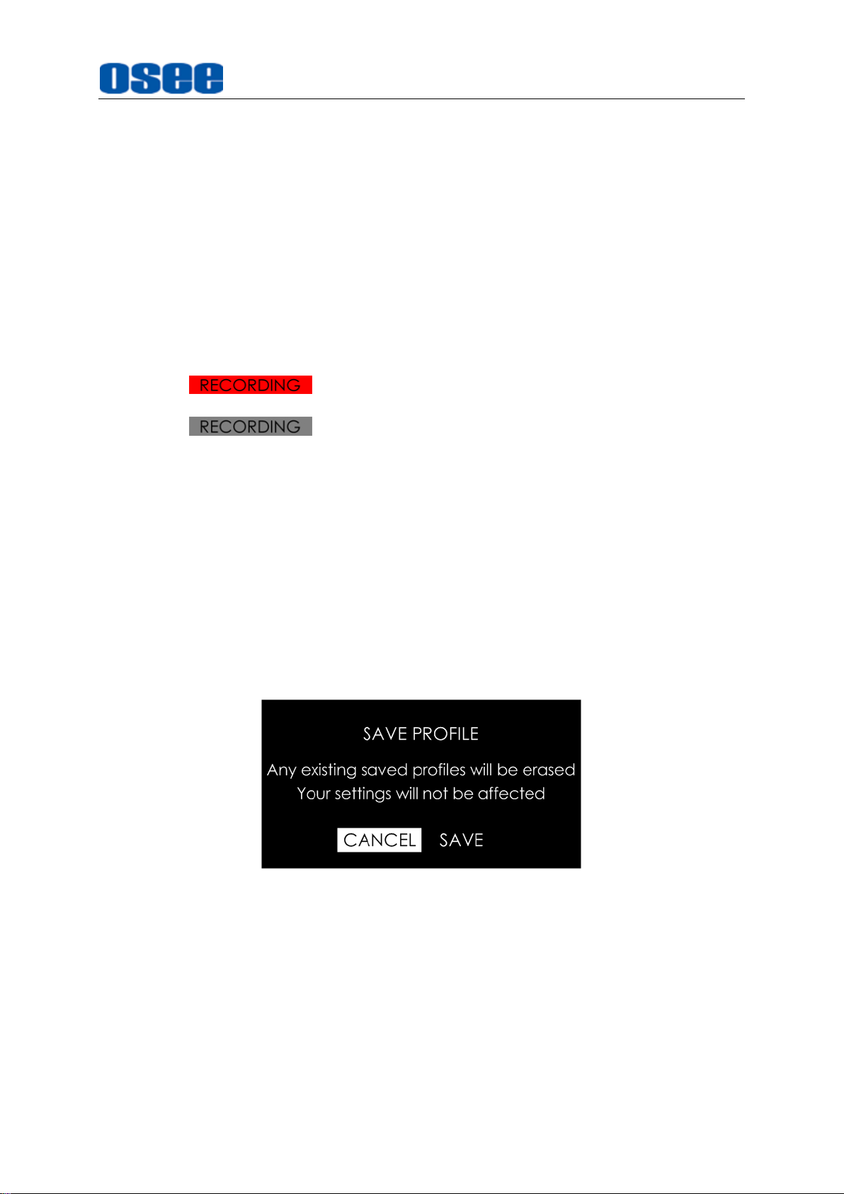
3. Data Save and Download
Save Settings: SAVE PROFILES TO SD CARD
Save the menu settings data to the external SD card as backup. The backup file
is saved in time sequence, and the file is named as
“jtj_backup_yyyymmddhhmmss.bin”.
usually displays as the following situations:
: appears if an unsupported signal is input.
: appears if no signal is detected.
: the signal format is displayed as HDMI 1080i59.94, SDI
Select
prompt, as shown in Figure 4.2-12. The old data in SD card will be erased, scroll
the joystick right to select
to confirm the selection, it will prompt not cutting off the power during saving
profiles, as shown in Figure 4.2-13:
userPROFILES SAVE PROFILES TO SD CARD
SAVE
Figure 4.2-12 Prompt for Saving Data
command, then, press the joystick straight down
item, it will pop up a
25
Page 32

Monitor Settings
It will pop up a prompt after successful saving data, as shown in Figure 4.2-14,
press the joystick straight down to confirm the completion.
Figure 4.2-13 Process of Saving Data
Figure 4.2-14 Prompt for Successful Saving Data
If detecting no SD card during the saving operation, it will prompt ”
not exist!
please check it according to this prompt.
The data saving to the SD card includes the settings on monitor and scenes, and
the files are recorded in time sequence.
Load Menu Settings: LOAD PROFILES FROM SD CARD
Read menu setting data from SD card, load and recover these parameters to the
current device.
Select
prompt a backup file list, as shown in Figure 4.2-15:
”; if any other wrong happened, it will pop up the corresponding prompt,
userPROFILESLOAD PROFILES FROM SD CARD
SD Card does
item, it will
26
Page 33

Figure 4.2-15 Backup File Selection List
Scroll the joystick up or down to the target file name, then press the joystick
straight down to confirm the selection, it will prompt as shown in Figure 4.2-16:
Monitor Settings
Figure 4.2-16 Prompt for Loading Profile
Select
operation, please don’t cut off the power during loading, as shown in Figure
4.2-17:
LOAD
command, then press the joystick straight down to confirm the load
Figure 4.2-17 Prompt for Loading Profile
27
Page 34

Monitor Settings
Menu
Items
Default
Domain Range
Description
CALIBRATION
CALIBRATION
OFF
NATIVE/
D65/
HIGH BRIGHT/
USER CAL LUT
Select a calibration
standard for the panel
CALIBRATION
LUT
…/info/user_de
fault.cl
--
--
Select a color look
profile as your desired
from SD card or internal
LUT files
RESET USER
CALIBRATION
LUT
--
--
Revert the LUT file to the
default one
BRIGHTNESS
50
0~100
Adjust the brightness
R-GAIN
128
0~255
Adjust the Red Gain
G-GAIN
128
0~255
Adjust the Green Gain
B-GAIN
128
0~255
Adjust the Blue Gain
RGB GAIN
RESET
--
--
Reset R,G,B GAIN
COLOR
RANGE
LEGAL
LEGAL:64~940/
EXTEND:1~1023
Set the color range
LANGUAGE
OPTIONS
中文
ENGLISH/
中文
Select a language mode
If detecting no SD card during the loading operation, it will prompt ”
does not exist!
”.
SD Card
4.2.4 System
The system menu provides calibration, language selection, firmware check and
factory reset operations, as shown in Figure 4.2-18:
Figure 4.2-18 System Menu
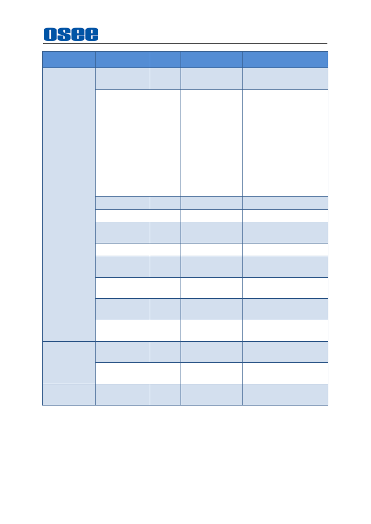
Table 4.2-5 Description of System Menu Items
28
Page 35
Menu
Items
Default
Domain Range
Description
WIFI
WIFI
OFF
ON/OFF
Enable/Disable WIFI
function
CHANNEL
AUTO
AUTO/
1(2412 MHz)/
2(2417 MHz)/
3(2422 MHz)/
4(2427 MHz)/
5(2432 MHz)/
6(2437 MHz)/
7(2442 MHz)/
8(2447 MHz)/
9(2452 MHz)/
10(2457 MHz)/
11(2462 MHz)/
Set communication
channel
MAC
--
--
MAC address
SSID
--
--
SSID name
SSID
PASSWORD
--
--
SSID password
LOGIN
admin
--
Login name
LOGIN
PASSWORD
admin
--
Login password
IP
192.168
.1.1
--
IP address
SAVE WIFI
SETTINGS
--
--
Save WIFI settings
RESET WIFI
SETTINGS
--
--
Reset WIFI settings
FIRMWARE
VERSION
--
--
Show the firmware
versions
SERIAL
NUMBER
--
--
Show serial number
FACTORY
RESET
--
--
--
Revert the factory
settings
Monitor Settings
1. Enable/Disable Calibration
Set
system CALIBRATION
shown in Figure 4.2-19:
item to display the CALIBRATION menu, as
29
Page 36
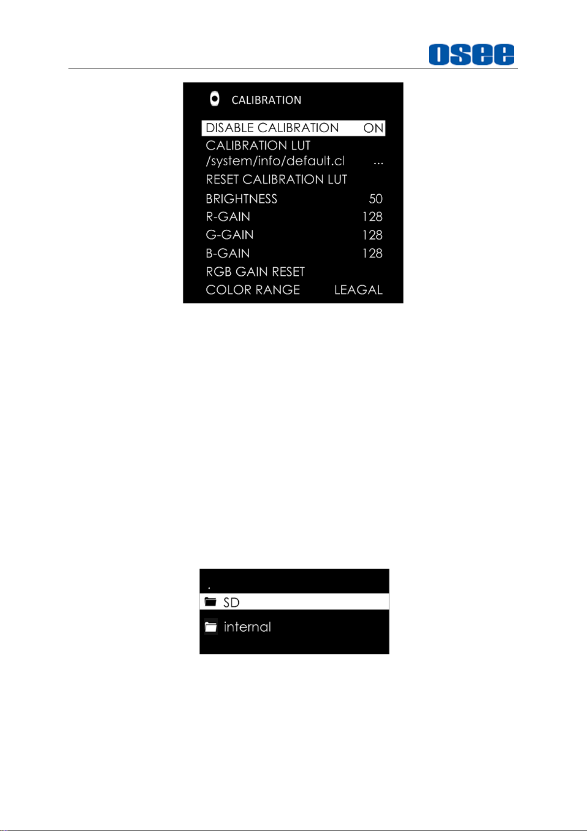
Monitor Settings
Figure 4.2-19 Calibration Menu
Set
system CALIBRATION DISABLE CALIBRATION
able to load LUT file.
Set
system CALIBRATION DISABLE CALIBRATION
be disable to load LUT file.
2. Load LUT File(1D LUT)
Select
/system/info/default.cl
Scroll the joystick right to display the menu, it contains two folders: SD and
internal
LUT file, so select the SD card, and scroll the joystick right again, it will list the
LUT files list, scroll up or down to select a LUT file, and press the joystick straight
down to confirm the selection, it will pop up a loading prompt, as shown in Figure
4.2-21:
system CALIBRATION CALIBRATION LUT
item to load a 1D LUT file from SD card.
, as shown in Figure 4.2-20. Particularly, only the SD card provides 1D
item as ON, it will be
item as
OFF
, it will
Figure 4.2-20 Calibration LUT Directory
30
Page 37
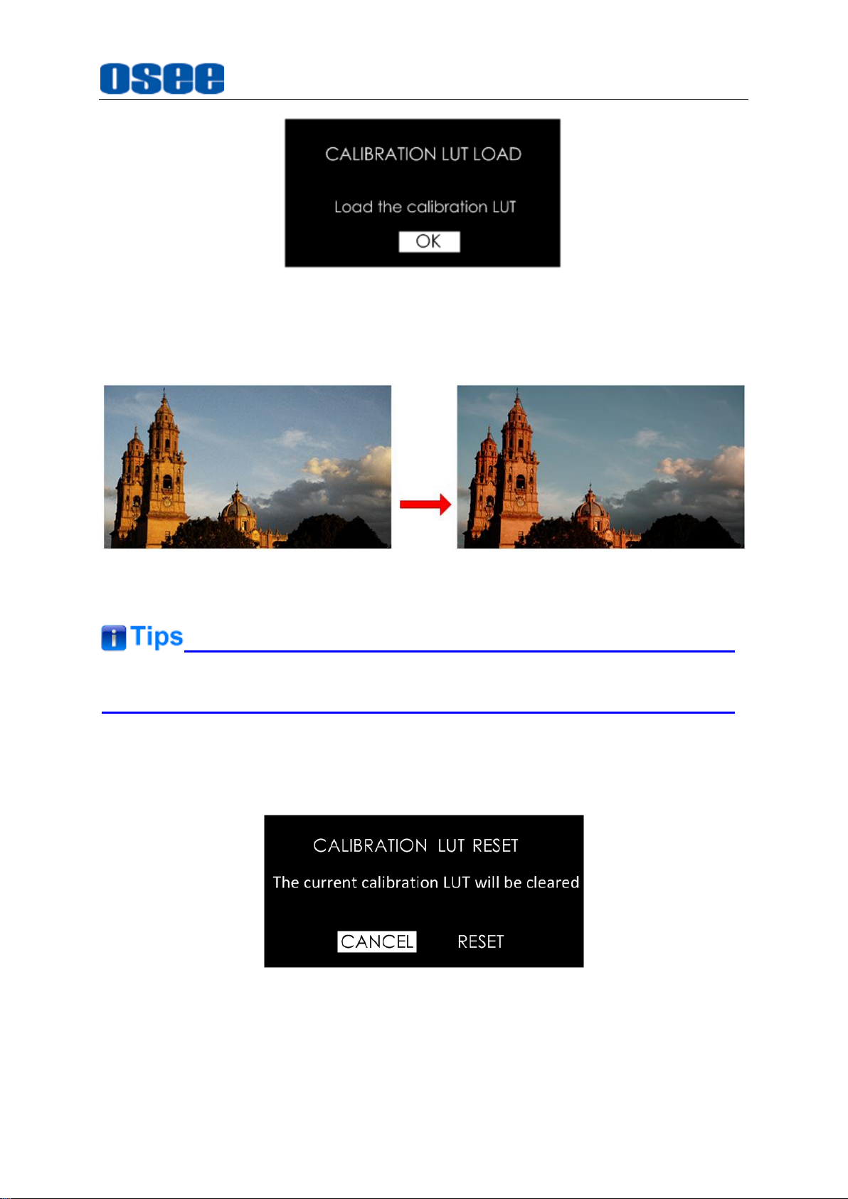
Figure 4.2-21 Load a LUT
After loading a LUT file, it will be loaded to the output image immediately, as
shown in Figure 4.2-22:
Monitor Settings
Figure 4.2-22 Output Image Loading a LUT File
Refer to “5.1.4 Look Tools” for the details about loading the 3D LUT file.
3. RESET CALIBRATION LUT
Select
the default LUT file, it will prompt as shown in Figure 4.2-23:
system CALIBRATION RESET CALIBRATION LUT
item to restore
Figure 4.2-23 Reset CALIBRATION LUT
It will revert the Gain and Offset values to default values for the current profile
selected in the
LOOK PROFILE
item.
31
Page 38
Monitor Settings
4. BRIGHTNESS
Set
system CALIBRATION BRIGHTNESS
Scroll left to decrease the brightness, or scroll right to increase the brightness.
5. R/G/B GAIN
Set
system CALIBRATION R-GAIN/G-GAIN/B-GAIN
values. Scroll left to decrease the gain, or scroll right to increase the gain.
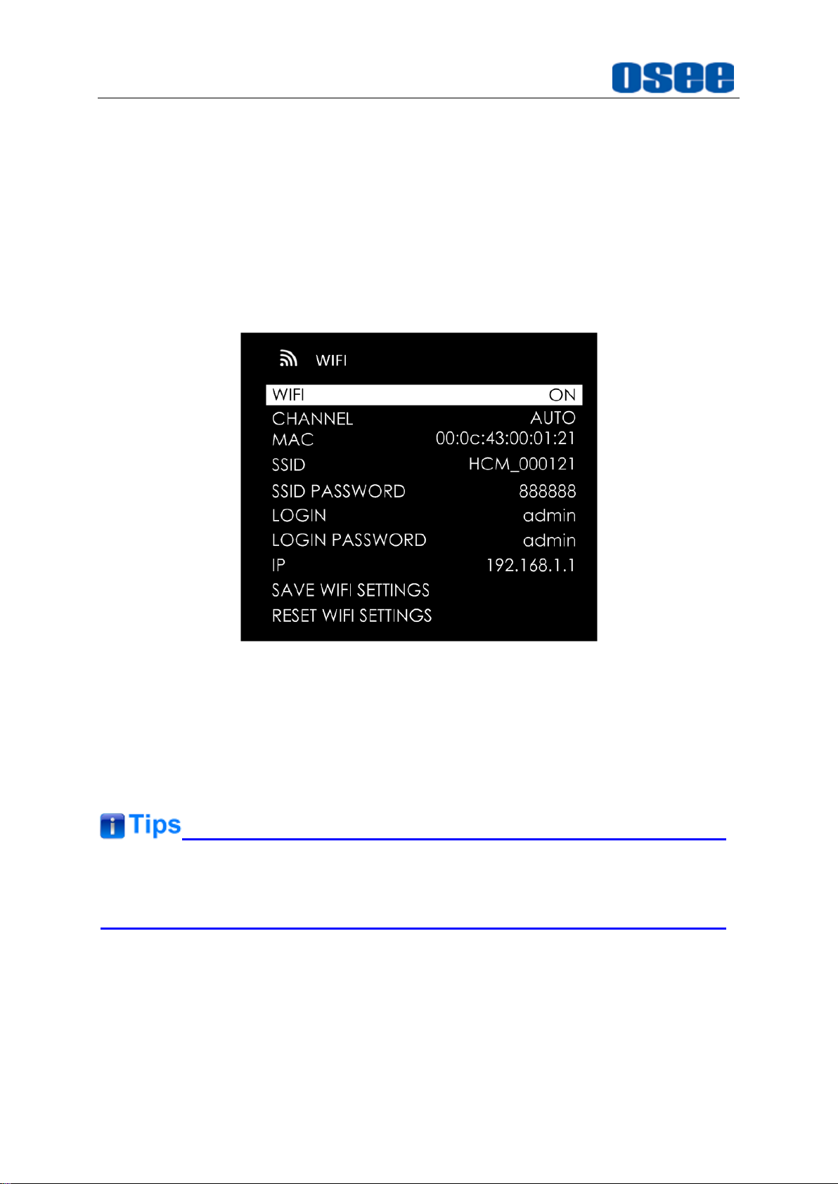
6. WIFI SETTINGS
Set
system WIFI WIFI
item as
to activate WIFI function.
ON
item to adjust the brightness.
item to adjust the gain
Figure 4.2-24 WIFI Menu
Connect WIFI:
system WIFI SAVE WIFI SETTINGS
Disconnect WIFI:
system WIFI SAVE WIFI SETTINGS
Select
item.
7. FACTORY RESET
Select
values, it will pop up a prompt, as shown in Figure 4.2-25 , scroll right to select
RESET
Please pay some patience during the reset operation, and it lasts about one
SAVE WIFI SETTINGS
system FACTORY RESET
command, and press the joystick straight down to confirm the selection.
Set
system WIFI
Set
system WIFI WIFI
item to effect the changes of WIFI or CHANNEL
item, thus, it will connect a WIFI;
item, thus, it will disconnect a WIFI.
item to initialize the settings to default
WIFI
item as
item as
, and choose
ON
, and choose
OFF
32
Page 39
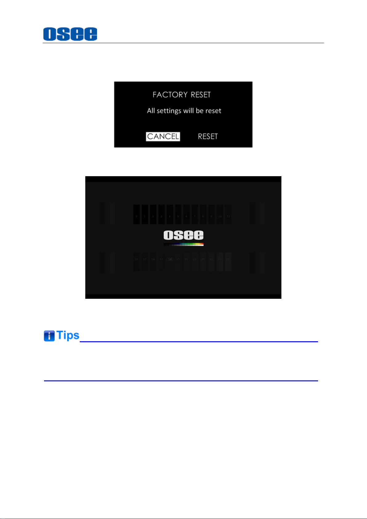
minute. The device will be in black screen mode for a short time after confirming
reset operation, then it will display the Boot Screen for successful reset operation,
as shown in Figure 4.2-26. At last, please restart the device by manual.
Figure 4.2-25 Prompt for Factory Reset
Monitor Settings
Figure 4.2-26 Boot Screen
It lasts about one minute for restarting operation, please don’t do any operations
during restarting the device.
33
Page 40

34
Page 41
Scenes and Tools
Chapter 5 Scenes and Tools
5.1 Scenes Tools Settings
You can create customized scenes pages with different features and settings in
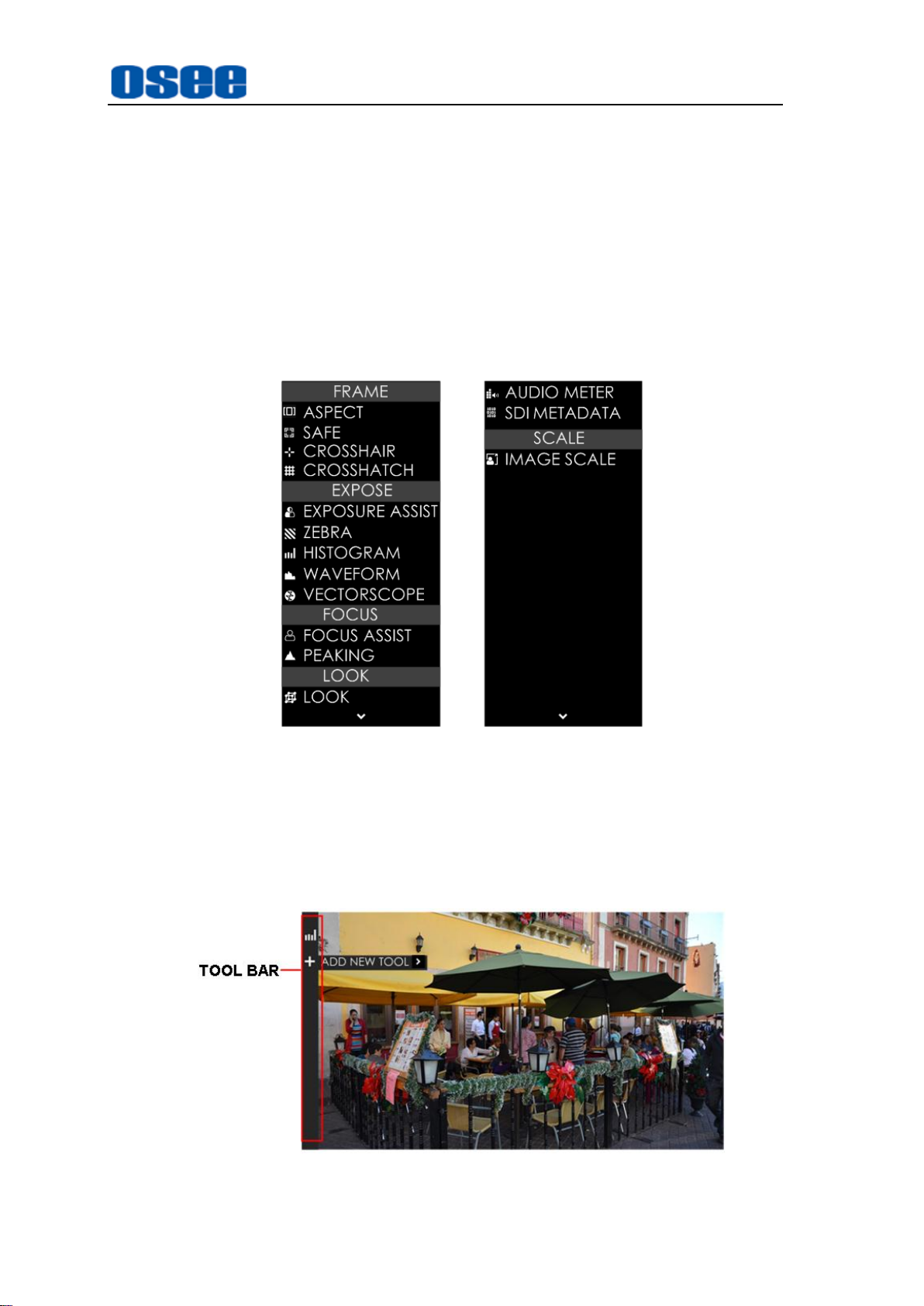
HCM-700. In a scene, press the joystick straight down, and select ADD NEW TOOL
command, and press the joystick straight down again, it will display the Tools Menu,
as shown in Figure 5.1-1.
Figure 5.1-1 Tools Menu for Scene
The tools menu provides access to tools aiding in composition, focus and exposure
for a scene, you can add several tools on a scene, then they will be listed in a tool bar,
as shown in Figure 5.1-2. After adding tools to the tool bar of a scene, you can edit the
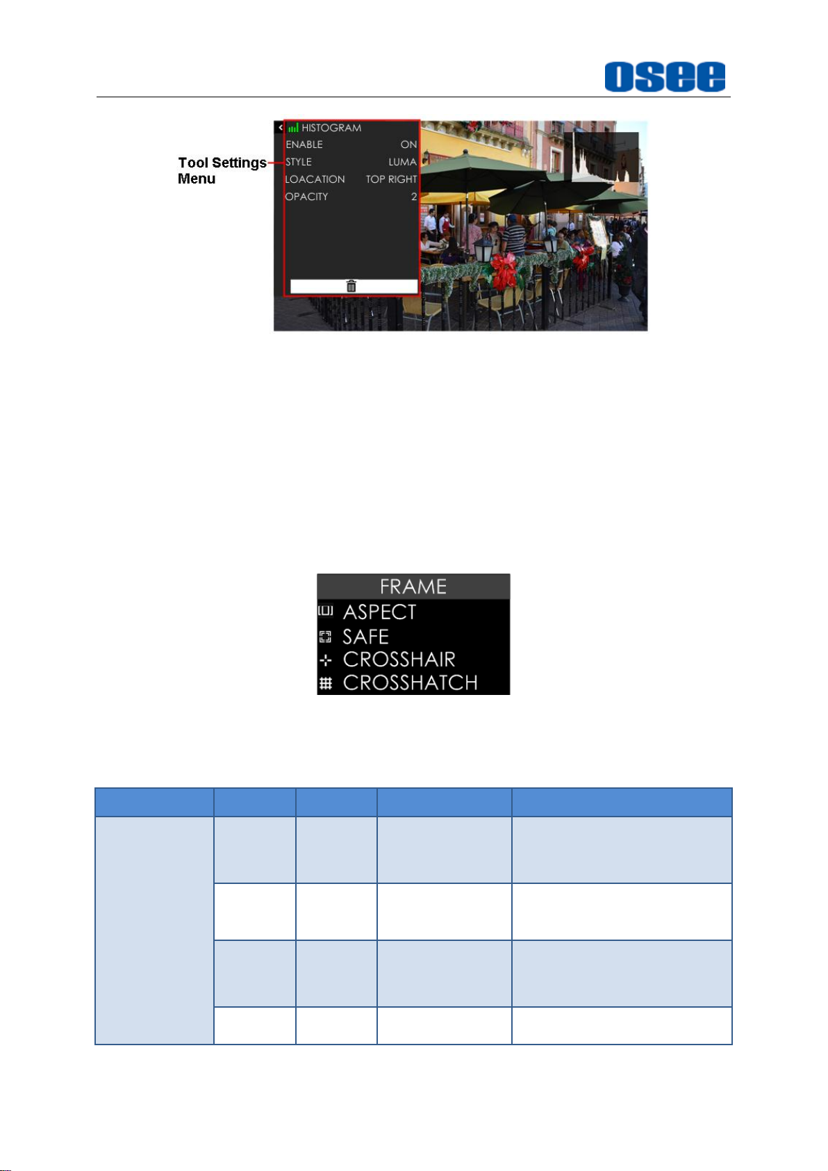
tool’s attributes by its tool settings menu, as shown in Figure 5.1-3:
Figure 5.1-2 Tool Bar for A Scene
35
Page 42
Scenes and Tools
Tool
Items
Default
Domain Range
Description
ASPECT
ENABLE
OFF
OFF/ON
Enable/Disable area
marker display
RATIO
4:3
4:3/1.85:1/2.39:1
/16:9/
CUSTOM
Select the marker type
WIDTH
75
25~100
Set the width of the mat
area in CUSTOM mode
HEIGHT
75
25~100
Set the height of the mat
It will introduce the tools and their attributes in the following section, and refer to “5.2
Tools Operations” for the details about tools operation.
Figure 5.1-3 Tool Settings Menu
5.1.1 Frame Tools
Frame tools assist to set viewing frame, including: aspect area, safe area, crosshair
and crosshatch. Show or hide these markers by their switches easily, and their display
style and transparency are adjustable.
Figure 5.1-4 Frame Tools
Table 5.1-1 Description of Frame Tools
36
Page 43

Tool
Items
Default
Domain Range
Description
area in CUSTOM mode
STYLE
MATTE
MATTE/LINE
Set the mat area type is 50%
darken area or line
SAFE
ENABLE
OFF
OFF/ON
Enable/Disable safe
marker display
FORMAT
16:9
16:9/14:9/4:3
Set the safe marker
position
ACTION
OFF
OFF/ON
The safe marker is
displayed as an outside
frame, proportional to
92% of the FORMAT
TITLE
OFF
OFF/ON
The safe marker is
displayed as an inside
frame, proportional to
80% of the FORMAT in
horizontal direction, and
90% of the FORMAT in
vertical direction.
CROSSHAIR
ENABLE
OFF
OFF/ON
Enable/Disable crosshair
display
STYLE
HOLLOW
HOLLOW:
CROSS:
Set the crosshair type is a
hollow or a cross
CROSSHATCH
ENABLE
OFF
OFF/ON
Enable/Disable crosshatch
display
REGIONS
2
2~9
Set the cross line number
Scenes and Tools
37
Page 44

Scenes and Tools
Marker
Illustration
Description
ASPECT
(AREA
MARKER)
This marker identifies an area
with a specified aspect ratio.
SAFETY
MARKER
This marker displays a rectangle
to identify the safety area with a
specified percentage in Area
Marker.
CROSSHAIR
(CENTER
MARKER)
This marker enables easier
checking the center portion’s
focus.
CROSS
HATCH
This marker displays multiple
vertical and horizontal lines to
help when users check the
composition of a picture.
1. Marker
2. Area Marker
Set the area marker by
WIDTH
And the outside area of the area maker could be filled with
FRAMEASPECTSTYLE
MATTE
and the
,
LINE:
MATTE:
and without lines, as shown in Figure 5.1-5:
HEIGHT
there are two white lines labeled the area marker;
the outside area of marker is 50% blackness of the background,
FRAMEASPECT
of the marker are adjustable as your requirement.
selection, you can choose it as
item. When set as
CUSTOM
MATTE
or
, the
LINE
. As
Figure 5.1-5 Marker Mat Style
38
Page 45

Tool
Items
Default
Domain Range
Description
EXPOSURE
ASSIST
ENABLE
OFF
OFF/ON
Enable/Disable false
color function
STYLE
NORMAL
NORMAL
ARRIR
RED
Set the type of the
false color display
IRE
OFF
OFF/ON
Enable/Disable IRE
guide bar display
IRE
LOCATION
RIGHT
OFF/ON
Set the position of
IRE guide bar
ZEBRA
ENABLE
OFF
OFF/ON
Enable/Disable the
zebra function that
will compare the
signal luminance
with the ZEBRA
LEVEL, and fill the
relevant image area
whose luminance is
higher than the
ZEBRA LEVEL with
a zebra pattern.
LEVEL
50
0~100
Set the reference
level of detecting
luminance.
HISTOGRAM
ENABLE
OFF
OFF/ON
Enable/Disable
histogram display
STYLE
LUMA
LUMA:
Set the type of the
Scenes and Tools
5.1.2 Expose Tools
Expose tools provide exposure assist (False Color), zebra, histogram, waveform and
vectorscope, as shown in Figure 5.1-6:
Figure 5.1-6 Expose Tools
Table 5.1-2 Description of Expose Tools
39
Page 46

Scenes and Tools
Tool
Items
Default
Domain Range
Description
luminance
histogram
RGB: RGB
histogram
histogram
LOCATION
TOP
RIGHT
TOP RIGHT
MID RIGHT
BOT RIGHT
MID BOT
BOT LEFT
MID LEFT
TOP LEFT
TOP MID
Set the position of
the histogram
OPACITY
0
0: 100%
1: 75%
2: 50%
3: 25%
Set the transparency
of the histogram
WAVEFORM
ENABLE
OFF
OFF/ON
Enable/Disable
waveform display
STYLE
LUMA
LUMA/RGB/
PARADE
Set the type of the
waveform
SIZE
NORMAL
NORMAL/MODE1/
MODE2/
Set the size of the
waveform
LOCATION
TOP
RIGHT
TOP RIGHT
MID RIGHT
BOT RIGHT
MID BOT
BOT LEFT
MID LEFT
TOP LEFT
TOP MID
Set the position of
the waveform
OPACITY
0
0~3
Set the transparency
of the waveform
VECTORSCOPE
ENABLE
OFF
OFF/ON
Enable/Disable
vectorscope display
LOCATION
TOP
RIGHT
TOP RIGHT
MID RIGHT
BOT RIGHT
MID BOT
BOT LEFT
MID LEFT
TOP LEFT
TOP MID
Set the position of
the vectorscope
40
Page 47
Tool
Items
Default
Domain Range
Description
OPACITY
0
0~3
Set the transparency
of the vectorscope
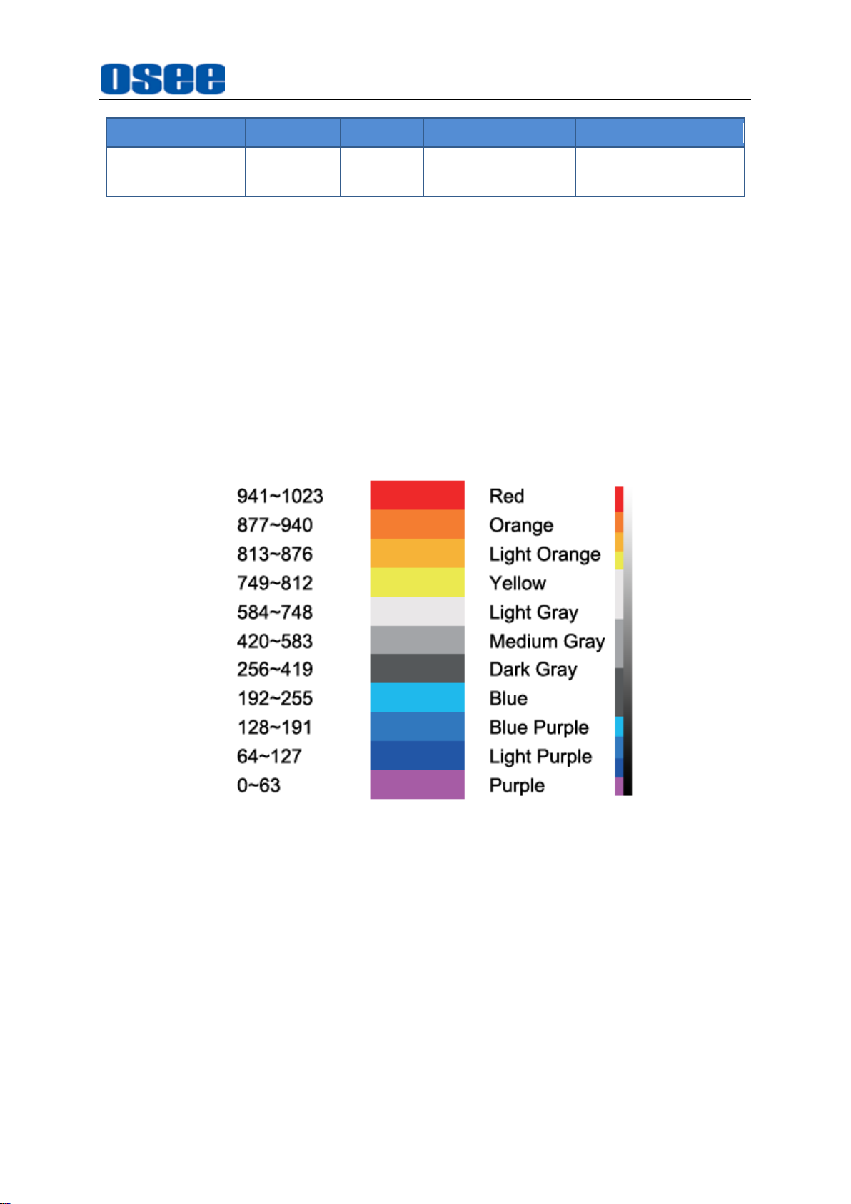
1. FALSE COLOR
EXPOSURE ASSIST is also known as FALSE COLOR, this function generates
an artificial luminance map of the input signal that can be useful to identify over
exposed areas(exposure). This is a quick way to gauge the exposure levels of an
image in a clear way.
Scenes and Tools
Choose the
FALSE COLOR tool. It provides three types of FALSE COLOR:
ARRIR, RED
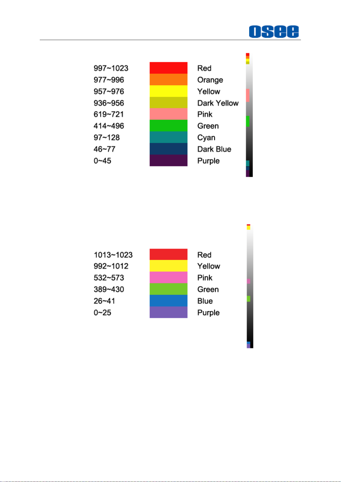
The following illustration indicates what artificial color corresponds to what
luminance level and the corresponding IRE guide bar.
NORMAL Mode
EXPOSURE ASSIST
.
tool to the current scene, and activate the
NORMAL
,
RED Mode
Figure 5.1-7 NORMAL Mode- Mapping of Color and Luminance
41
Page 48
Scenes and Tools
Figure 5.1-8 RED Mode- Mapping of Color and Luminance
ARRIR Mode
Figure 5.1-9 ARRIR Mode- Mapping of Color and Luminance
For example:
EXPOSURE ASSIST STYLE
item as ON, and
in Figure 5.1-10:
Set
EXPOSURE ASSIST ENABLE
EXPOSURE ASSIST IRE LOCATION
item as
42
NORMAL, EXPOSURE ASSIST IRE
item as ON, set
item as ON, as shown
Page 49
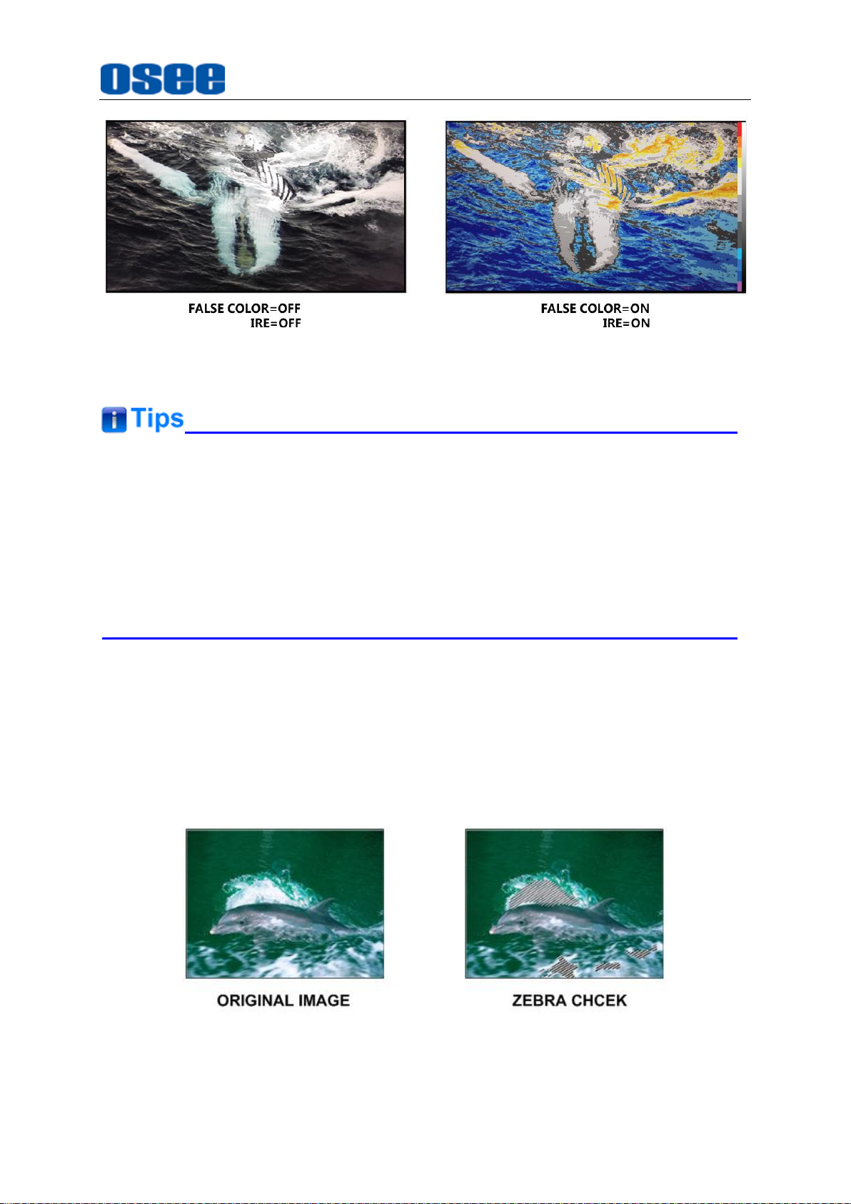
Figure 5.1-10 Comparison Mode- Original Image and Normal Mode Image
Scenes and Tools
The LOOK tool is incompatible with the False Color(
That is, enable the LOOK tool, the False Color tool will be disabled automatically,
and enable the False Color tool, the LOOK tool will be disabled automatically.
Set
EXPOSURE ASSIST ENABLE
bar display.
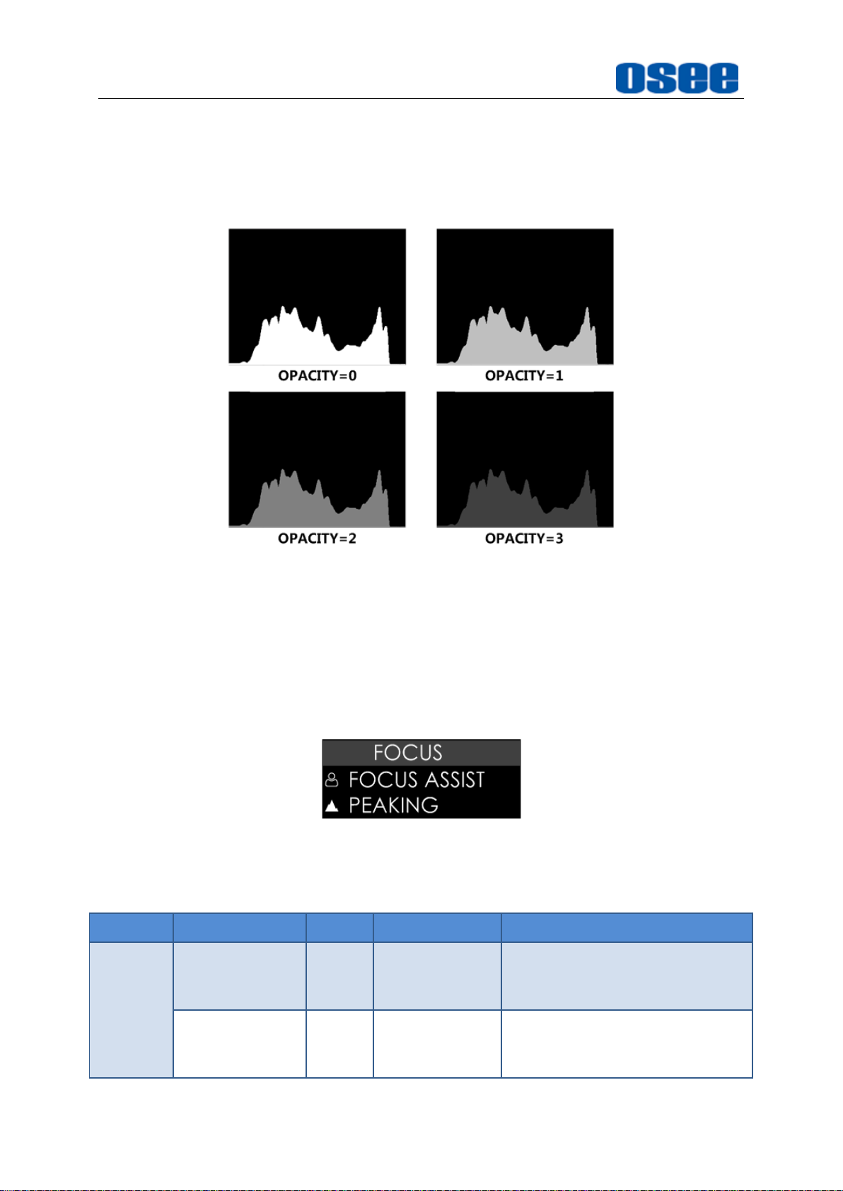
2. ZEBRA
The
ZEBRA
to adjust the camera exposure parameter. It will compare the signal luminance
with the
higher than the
For example
in Figure 5.1-11, the special area is filled with a zebra pattern.
function is used to display images on the screen with a zebra pattern
ZEBRA LEVEL
ZEBRA LEVEL
, set the
, and fill the relevant image area whose luminance is
ZEBRA LEVEL
item as ON is a prerequisite for IRE guide
with a zebra pattern
as 80, the compared results are as shown
EXPOSURE ASSIST
) tool.
Figure 5.1-11 Illustration for LUMA ZOOM CHECK Function
3. HISTOGRAM
43
Page 50

Scenes and Tools
Histogram assists in judging the distribution of luminance in the image.
Histogram Type
Set
EXPOSEHISTOGRAMSTYLE
types are as shown in Figure 5.1-12:
Figure 5.1-12
4. WAVEFORM
WAVEFORM SIZE
Set
EXPOSEWAVEFORMSIZE
there are three kinds of sizes for waveform:
RGB Histogram and LUMA Histogram
item as LUMA or RGB, the two histogram
item to adjust the size of the waveform,
Small size waveform: set
waveform could be located in any one of the 8 positions listed in
LOCATION
75% waveform: set
located in the center bottom of the screen, and it can’t be moved;
Full size waveform: set
located in the bottom of the screen, and it can’t be moved.
WAVEFORM TYPE
Set
EXPOSEWAVEFORMSTYLE
waveform as LUMA, RGB, PARADE, as shown in Figure 5.1-13:
item;
SIZE
SIZE
item as
item as
SIZE
MODE1,
item as
item to display the following three kinds of
MODE2,
NORMAL,
and this kind of waveform is
and this kind of waveform is
and this kind of
Figure 5.1-13 LUMA
Waveform and RGB Waveform and PARADE Waveform
44
Page 51

5. VECTORSCOPE
Scenes and Tools
Set
EXPOSEVECTORSCOPEENABLE
vectorscope.
Figure 5.1-14 VECTORSCOPE
6. LOCATION
There are 8 positions for display the histogram, waveform and vectorscope on
the screen, they are TOP RIGHT, MIDDLE RIGHT, BOTTOM RIGHT, MIDDLE
BOTTOM, BOTTOM LEFT, MIDDLE LEFT, TOP LEFT, and TOP MIDDLE, as
shown in Figure 5.1-15. Move them through the
item to display or hide the
LOCATION
item.
Figure 5.1-15 Location of the Assistant Elements
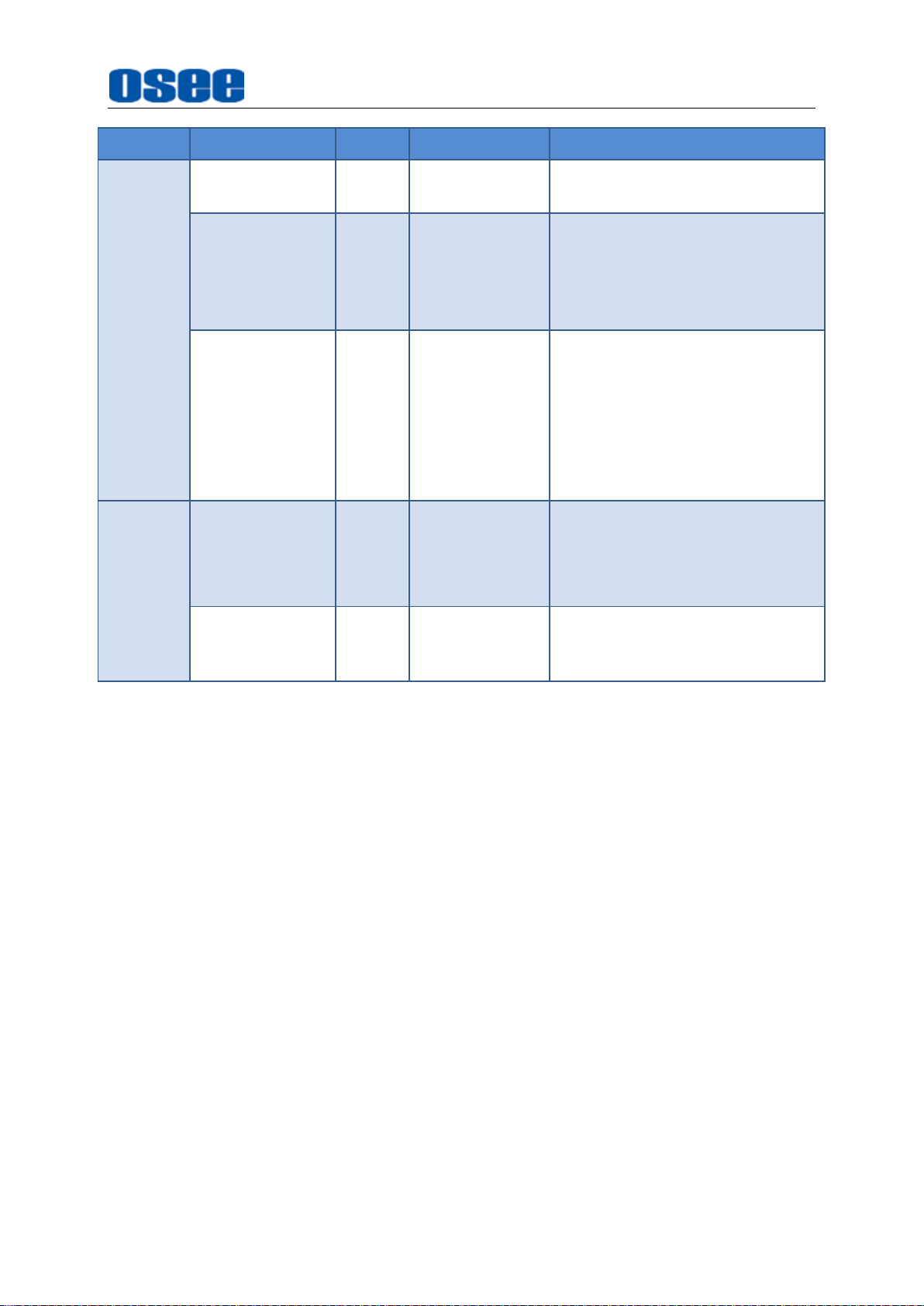
7. OPACITY
There are 4 degrees of opacity for display the histogram, waveform and
vectorscope on the screen. Set the transparency through the
0: 100%, when opacity set to 0, the assistant element (histogram,
waveform or vectorscope) is opaque, not transparent.
1: 75%, when opacity set to 1, the assistant element (histogram,
waveform or vectorscope) is proportional to 75% opacity.
2: 50%, when opacity set to 2, the assistant element (histogram,
waveform or vectorscope) is proportional to 50% opacity.
OPACITY
item.
45
Page 52
Scenes and Tools
Tool
Items
Default
Domain Range
Description
FOCUS
ASSIST
ENABLE
OFF
OFF/ON
Enable/Disable focus assist
function
COLOR
RED
STANDARD/
RED/GREEN/
BLUE
Select the color of the focus
assist edge.
For standard color, the
3: 25%, when opacity set to 3, the assistant element (histogram,
waveform or vectorscope) is proportional to 25% opacity.
For example:
the comparison are as below:
set
EXPOSEHISTOGRAM OPACITY
Figure 5.1-16 Different Opacity for Histogram
as 0, 1, 2, 3 separately,
5.1.3 Focus Tools
Focus tools provide the focus assist function and the peaking function. Set display
color, sensitivity and display type for focus assist, and set intensity for peaking
detecting.
Figure 5.1-17 Focus Tools
Table 5.1-3 Description of Focus Tools
46
Page 53
Tool
Items
Default
Domain Range
Description
intensified edges highlight in
white.
SENSITIVITY
5
1~10
Set the edge difference value
between the edges in an image,
and take this value as the
reference value. Larger value
means more detail detection.
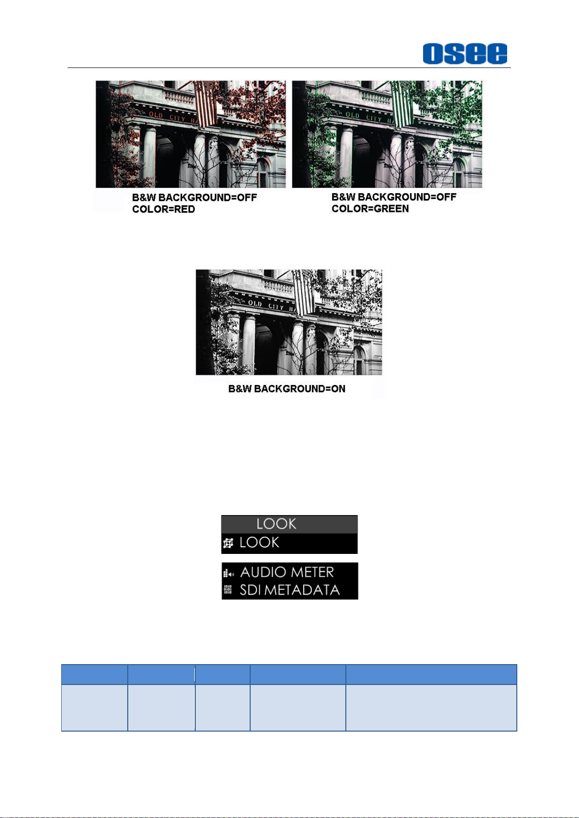
B&W
BACKGROUND
OFF
OFF: COLOR
MODE
ON: BLACK
&WHITE
MODE
Set the focus assist display
mode: color mode or
black&white mode.
PEAKING
ENABLE
OFF
OFF/ON
Enable/Disable peaking
function
Over sharpen the image.
INTENSITY
5
1~10
Set the sharpness level of the
image. The higher the value, the
sharpener the image.
Scenes and Tools
1. FOCUS ASSIST
The FOCUS ASSIST function is used to display images on the screen with
intensified edge to help camera focus operation. The intensified edges are those
areas whose difference value exceeds the reference focus level (
and the intensified edge are displayed in the designated color set by
FOCUS ASSIST MODE
COLOR MODE
item as
ASSIST COLOR
B$W MODE
item as ON, the image is in black and white mode, that is removing all
colors and only leaving the luminance data of the signal.
OFF
: Set
FOCUS FOCUS ASSIST B&W BACKGROUND
, the image is in color mode, then set
to color the intensified edge.
: Set
FOCUS FOCUS ASSIST B&W BACKGROUND
SENSITIVITY
COLOR
FOCUS FOCUS
.
),
47
Page 54
Scenes and Tools
Tool
Items
Default
Domain Range
Description
LOOK
ENABLE
OFF
OFF/ON
Enable/Disable LUT profile
function
Figure 5.1-18 Illustration for FOCUS ASSIST Function
Figure 5.1-19 Illustration for FOCUS ASSIST Function
5.1.4 Look Tools
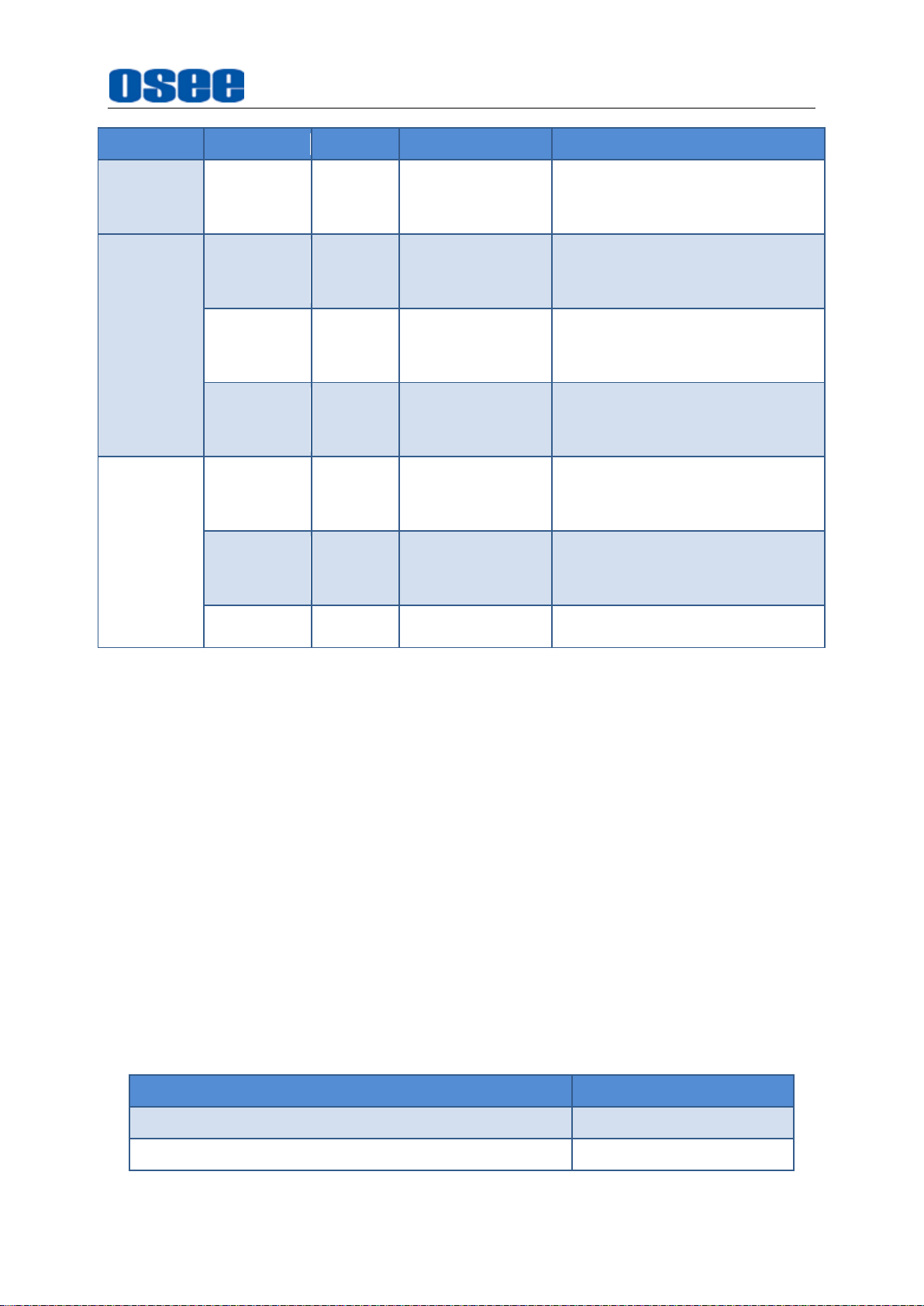
Look tools provides loading 3D LUT profile, adding audio meter or SDI metadata to
current scene, as shown in Figure 5.1-20
Figure 5.1-20 Look Tools
Table 5.1-4 Description of Look Tools
48
Page 55
Tool
Items
Default
Domain Range
Description
LOOK FILE
-- --
Select a 3D LUT profile for
current scene
AUDIO
METER
ENABLE
OFF
OFF/ON
Enable/Disable audio meter
display
LOCATION
BOT
LEFT
BOT LEFT
/
BOTRIGHT
Set the position of the audio
meter
OPACITY
0 0~3
Set the transparency of the
audio meter
SDI
METADATA
ENABLE
OFF
OFF/ON
Enable/Disable SDI
METADATA function
TIEMCODE
OFF
OFF/ON
Enable/Disable TC code
display
RECORD
OFF
OFF/ON
Enable/Disable RTC function
Preset LUT File
Description
AlexaV3_EI0800_LC2_Rec709_EE.osl
ARRI
BMD CC Film to Rec709 v2.osl
BlackMagic
Scenes and Tools
1. LOOK PROFILE(3D LUT)
The monitor is equipped with versatile color lookup profiles for different
requirements, we provide the following LUT profiles:
Internal:9 camera log,
SD Card
3D LUTs from SD card.
Select
or internal files.
There are 9 preset 3D-LUT tables, supporting the LUT files for ARRI, RED, SONY,
Panasonic, Canon, BlackMagic and Panavision, etc.
LOOK LOOK LOOK FILE
Preset LUT File(Internal)
: HCM-700 monitor is capable of loading customized calibration
Table 5.1-5 Internal LUT Files
as shown in Table 5.1-5;
item to choose a 3D LUT file from SD card
49
Page 56

Scenes and Tools
Preset LUT File
Description
BMD PC 4K Film to Rec709 v2.osl
BlackMagic
Canon_EE_Cin_CL1_WDR.osl
Canon
Canon_EE_Cin_CL2_WDR.osl
Canon
Pana VLog_to_V709_forV35.osl
Panasonic
RED_EE_RLF_RG3.osl
RED
SONY_EE_Slog2_LC709A.osl
SONY
SONY_EE_Slog3C_L709A.osl
SONY
The internal LUT files are constantly under development.
HCM-700 supports color management software CalMAN currently, the
customized 3D LUT profiles(*.cube) produced by these softwares could be loaded
to SD card by a control computer.
You can place the customized 3D LUT profiles(*.cube) directly on an SD card,
either on the root directory or organize them by folders.
The LOOK tool is incompatible with the False Color(
That is, enable the LOOK tool, the False Color tool will be disabled automatically,
and enable the False Color tool, the LOOK tool will be disabled automatically.
2. AUDIO METER
Set
LOOKAUDIO METERENABLE
audio meter on screen.
The audio meter could be displayed at the left bottom or right bottom of the
screen, and the opacity could be set from 0 to 3. Refer to “5.1.2 Expose Tools--7
OPACITY” for the details about OPACITY.
The volume in normal range appears in green, above -20dB but below -10dB
appears in yellow, and above -10dB appears in red, as shown in Figure 5.1-21:
item as ON to enable the display of
EXPOSURE ASSIST
) tool.
3. TIME CODE
Figure 5.1-21 Audio Meter
50
Page 57
Tool
Items
Default
Domain Range
Description
SCALE
ENABLE
OFF
OFF/ON
Enable/Disable image
scale function
SIZE
75
20~100
Set image display size
LOACTION
TOP LIGHT
TOP RIGHT
MID RIGHT
BOT RIGHT
MID BOT
BOT LEFT
MID LEFT
TOP LEFT
TOP MID
CENTER
Set image position on
screen
Scenes and Tools
Select
timecode on screen, only valid for SDI input signal.
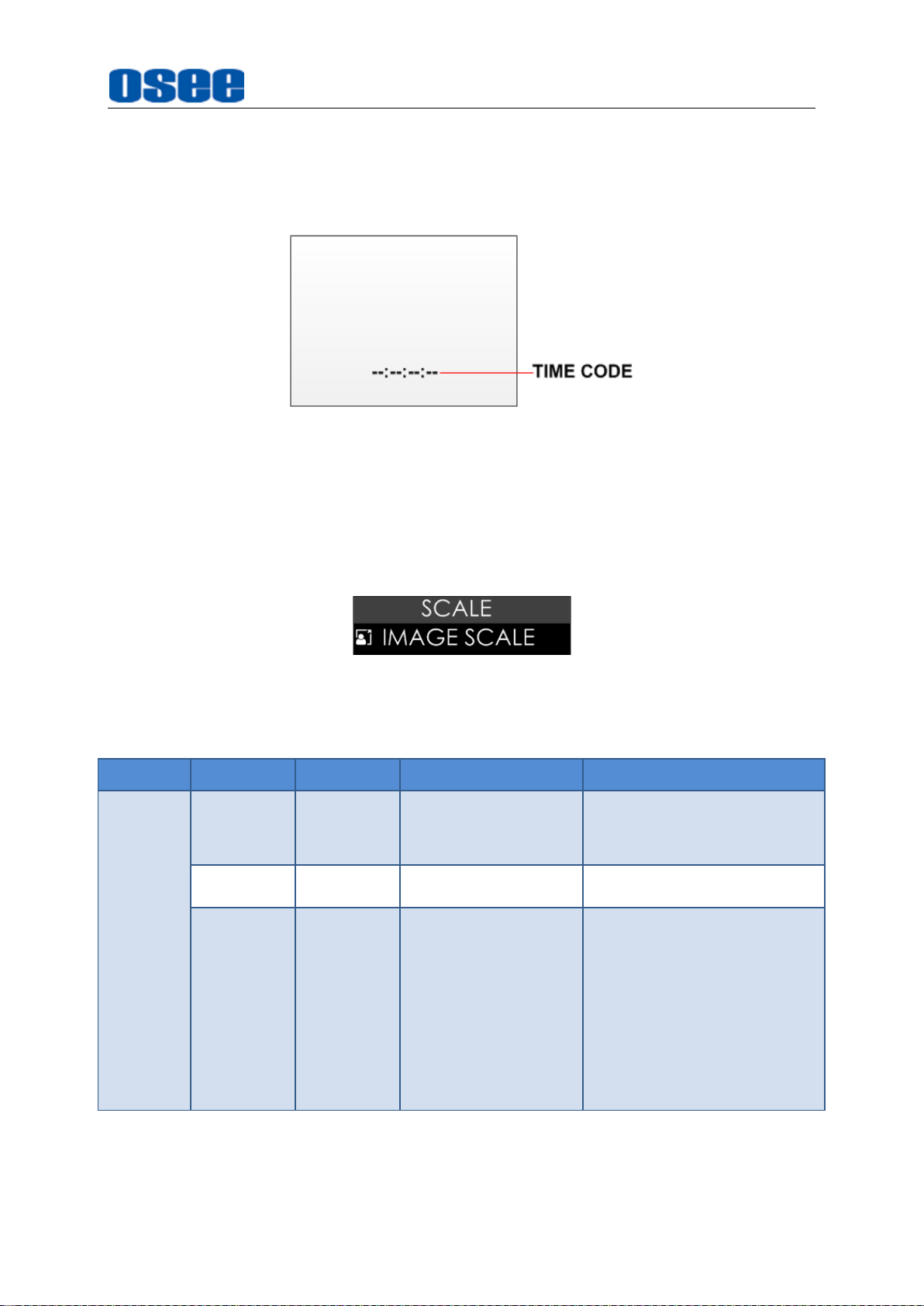
Timecode is displayed as the format of “HH:MM:SS:FF” at the bottom center of
the screen, and if there is no available timecode, it will not appear.
SDI METADATATimecode
Figure 5.1-22 Timecode
item to enable the display of embedded
5.1.5 Scale Tools
Scale tool is used to adjust the horizontal and vertical size of the screen, as shown in
Figure 5.1-23
Figure 5.1-23 Scale Tools
Table 5.1-6 Description of Scale Tools
1. IMAGE SCALE
Activate Image Scale Function
51
Page 58

Scenes and Tools
Set
SCALE SCALE ENABLE
image size could be adjustable by
Image Size
Set
SCALE SCALE SIZE
After scaling down, the blank area will be filled with black, as shown in Figure
5.1-24:
Figure 5.1-24 Scale Illustration
Image Position
item as
SIZE
item from 20 to 100 to change the image size.
item.
the image scale is activated. The
ON,
There are 9 positions for display the small image on screen, they are TOP RIGHT,
MIDDLE RIGHT, BOTTOM RIGHT, MIDDLE BOTTOM, BOTTOM LEFT, MIDDLE
LEFT, TOP LEFT, TOP MIDDLE and CENTER, as shown in Figure 5.1-25. Move
it through the
LOCATION
item.
Figure 5.1-25 Image Position
5.2 Tools Operations
It will introduce how to edit scene and its tools in this section.
52
Page 59

Scenes and Tools
5.2.1 Add a Scene
You can customize up to 8 scenes in HCM-700 for various requirement, and switch
swiftly among these scenes by joystick operations.
Scroll the joystick right to add a new scene, it will prompt “Add New MySet ”
command in the bottom center of the screen, press the joystick straight down to
confirm the operation.
The scene will be numbered in sequence, and the name (a scene icon followed by a
number) will be displayed at the bottom center of the screen, as shown in Figure
5.2-1:
Figure 5.2-1 A New Scene
HCM-700 supports up to 8 customized scenes.
Scroll the joystick left or right to switch among scenes.
5.2.2 Delete a Scene
Scroll the joystick down in a scene, it will display the DELETE command at the bottom
of the screen, as shown in Figure 5.2-2. Press the joystick straight down to confirm
deletion, and there will be a waiting prompt during the deletion. Wait until the prompt
disappeared, then the scene deletion is completed.
Figure 5.2-2 Prompt for Delete a Scene
53
Page 60

Scenes and Tools
5.2.3 Add a Tool
After creating a scene, add some tools to assist in composition, for example, add a
marker, waveform, histogram or audio meter, etc.
Each scene supports up to 8 scene tools.
You can add more than one of the same tool in a scene.
Scroll the joystick down, it will pop up the “ADD NEW TOOL” command, as shown in
Figure 5.2-3. Press the joystick straight down to confirm, and it will pop up the Tools
Menu on screen, as shown in Figure 5.2-4:
Figure 5.2-3 Add a New Tool
Figure 5.2-4 Tools Menu for Scene
Scroll the joystick up or down to select your desired scene tool, and press the joystick
straight down to confirm, the selected tool will be added to the Tool Bar of the current
scene.
For example: Add histogram to Tool Bar
Scroll the joystick up or down to HISTORGRAM item, as shown in Figure 5.2-5, press
54
Page 61
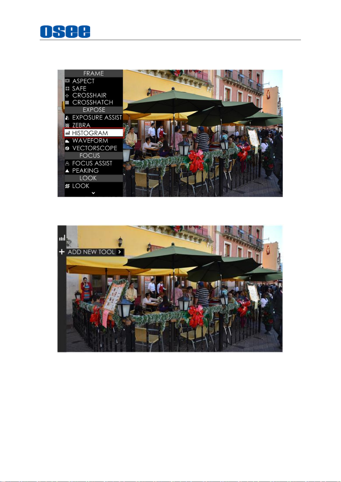
the joystick straight down to confirm the selection, the HISTORGRAM,tool will be
added in the tool bar, as shown in Figure 5.2-6:
Scenes and Tools
Figure 5.2-5 Choose Histogram Tool
Figure 5.2-6 Histogram in the Tool Bar
Continue to add other tools for the scene, you can add up to 8 tools in a scene.
5.2.4 Load/Close Tool Bar
In a scene, after added the tools, you can load the tool bar or close the tool bar. The
instructions are as below:
55
Page 62

Scenes and Tools
Load Tool Bar
, scroll the joystick right to enter into a scene;
First
Second
the tool bar will be displayed the leftmost of the screen, as shown in Figure 5.2-7.
The bar labeled in the red rectangle are the tool bar for the current scene.
, press the joystick straight down to load the tool bar for the current scene,
Figure 5.2-7 Tool Bar for A Scene
Close Tool Bar
After loading a tool bar, scroll the joystick left or press
to close the tool bar.
When in editing tool setting menu status, press
return to the previous menu, then scroll the joystick left or press
button to close the tool bar.
Open tool setting menu
After loading a tool bar, scroll the joystick right to enter into tool settings menu, as
shown in Figure 5.2-8
BACK
BACK
button
button to
BACK
56
Page 63

Figure 5.2-8 Tool Setting Menu
Scenes and Tools
Press
menu.
BACK
button to return to the tool bar and close the tool setting
5.2.5 Open/Close a Tool
Follow the instructions below to open or close a tool swiftly:
Open a Tool
First, press the joystick straight down to load the tool bar of the current scene;
Second, scroll the joystick up or down to select a tool;
At last, press the joystick straight down to open the tool.
Close a Tool
Press the joystick straight down to close the tool after opened it.
Select a Tool
Scroll the joystick up or down to select a tool after loading the tool bar.
The tool icon in the tool bar will change in highlight green of opened status, and
will change in white of closed status.
5.2.6 Tool Settings
Add tools for a scene through the tool settings, then, set a tool’s attributes by scrolling
the joystick right, it will display the tool settings menu on the screen.
57
Page 64

Scenes and Tools
Scroll the joystick left or right to switch among different scenes. The tool bar is hidden
when switching to a scene by default. You should press the joystick straight down to
display the tool bar for the current scene.
Operate the tool bar to display each tool settings menu, and set the style, location or
size of the tool. Refer to “5.1 Scenes Tools Settings” for the details of each tool.
For example: Display histogram on a scene.
In a scene, press the joystick straight down to display the tool bar at the left side of the
screen. Scroll the joystick down to move the cursor onto the HISTOGRAM tool icon,
as shown in Figure 5.2-9:
Figure 5.2-9 Select HISTOGRAM
Press the joystick straight down to load the histogram window on the screen, and the
histogram icon is lit in highlight green, as shown in Figure 5.2-10. Or press the joystick
straight down again to close the histogram window.
Figure 5.2-10 Display the Histogram
58
Page 65
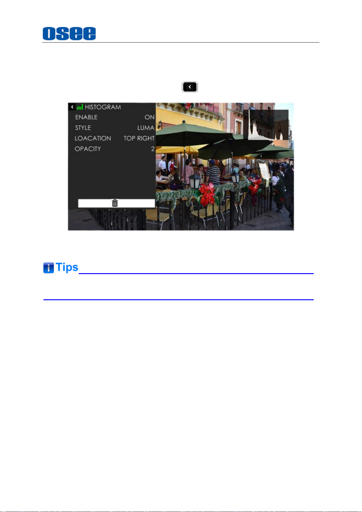
Scroll the joystick right to enter into the next level menu, it will display the histogram
settings menu, as shown in Figure 5.2-11. It lists the characteristics of histogram in
this menu, such as STYLE, LOCATION, OPACITY and ENABLE switch. After finish
the parameter settings, press BACK button to return to the tool bar.
Scenes and Tools
Figure 5.2-11 Settings Menu for Histogram
The parameters of the tool could not be modified until the tool is opened.
5.2.7 Delete a Tool
In a scene, press the joystick straight down to display the tool bar for current scene,
and scroll the joystick up or down to select the tool which you want to delete, then
scroll right to enter the tool setting menu, and select DELETE command at the end of
the menu list, as shown in Figure 5.2-12.
59
Page 66

Scenes and Tools
Press the joystick straight down to confirm the selection, and it will pop up a prompt to
confirm the deletion, as shown in Figure 5.2-13, press straight down to delete, then
the tool will be deleted from its tool bar.
Figure 5.2-12 Delete a Tool
Figure 5.2-13 Prompt for Deleting a Tool
The effect or window displayed on the current scene will be closed after the
corresponding tool is deleted.
60
Page 67
Specifications
Specification
Values
Model
HCM-700
Display
Dimension
7”
Aspect Ratio
16:10
Viewing Angle (HxV)
178°
Color Depth
8bit
Resolution
1920×1200
Contrast
1200:1
Brightness
1100nits
Input/Output Signal Formats
3G-SDI(Input/Output)
1080P60, 1080P59.94, 1080P50
HD-SDI(Input/Output)
1080p30, 1080p25, 1080p24, 1080p23.98,
1080i60, 1080i59.94, 1080i50, 1080pSF30,
1080pSF29.97, 1080pSF25, 1080pSF24,
1080pSF23.98, 720p60, 720p59.94, 720p50
HDMI(Input/Output)
1080P60, 1080P59.94, 1080P50, 1080p30,
1080p25, 1080p24, 1080p23.98, 1080i60,
1080i59.94, 1080i50, 1080pSF30,
1080pSF29.97, 1080pSF25, 1080pSF24,
1080pSF23.98, 720p60, 720p59.94, 720p50
Audio(Input)
SDI/HDMI Embedded
Connector Type
SDI
BNC
HDMI
HDMI Type A
Audio
3.5mm Mini Jack
Power In
5.5/2.5mm Locking DC IN; Battery Plate
WIFI
SMA Female
Power
Power Voltage
11~17V DC IN; 6.0~8.4V from Battery IN
Chapter 6 Specifications
6.1 Product detailed information
61
Page 68

Specifications
Specification
Values
Power Consumption
12W Typ. 15W Max.
Battery Types
Canon LP-E6/ Sony L Series
Environmental
Operating Temperature
30F~90F/ 0°C~35°C
Storage Temperature
0F~120F/ -20°C~50°C
Screen Protection
1mm Acrylic
Dimensions(Bare Monitor)
4.56’’(11.57cm)
×
7.61’’(19.32cm)
×
1.01’’(2.57cm)
Weight(Item Only without Battery)
650g
Mount Points
(3)1/4-20 thread points(top, bottom, back)
Features
Image Scale
Yes
Anamorphic De-squeeze
Yes Image Rotate
Yes
Cross Hatch
Yes
Center Marker
Yes
Safe Marker
Yes Area Marker
Yes
Focus Assist
Yes
Peaking
Yes
Pixel Zoom
(2X & 4X)
Yes False Color
Yes
Zebra
Yes
Waveform
Yes
Vectorscope
Yes
RGB
Parade
Yes
62
Page 69

Specifications
Specification
Values
Histogram
Yes
Audio Meters
Yes Pre-loaded
LUTs for Cameras
Yes
LUT Loaded via SD Card
Yes
LUT Loaded via WIFI
Future Upgrade
Firmware Upgrading
Yes
Language(EN
/CH)
Yes
Type
Model
Description
Battery Plate
HCM-BM-SC
Battery plate
Sunhood suit
HCM-700-HOOD
Sunhood
Protective screen
HCM-700-Cover
Protective screen
Protective Case
HCM-700-PB
Protective Case
*The unit about the appearance attributes in above table is mm.
6.2 Optional Accessories
You can select the following accessories for LCM-E series monitors optionally:
1. Battery Plate
If you want to use battery as your backup power supply, you can choose the
battery plate listed in the optional accessories table above: as shown in Figure
6.2-1:
63
Page 70

Specifications
Figure 6.2-1 AB-mount Battery Plate in Landscape
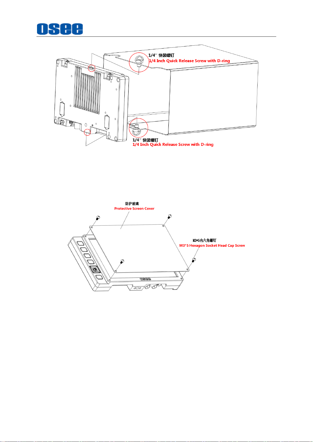
2. Sunhood
In case of diffusion light and direct illumination, we can use sunhood for the
HCM-700 monitor when supervising images. Mount the sunhood as shown in
Figure 6.2-2, and Figure 6.2-3:
Figure 6.2-2 Mount a Sunhood
64
Page 71
Specifications
3. Protective Screen
Figure 6.2-3 Mount a Sunhood
Choose the protective screen to protect your monitor screen. Mount the
protective screen as shown in Figure 6.2-4:
Figure 6.2-4 Mount a Protective Screen
4. Protective Case
Each monitor and its accessories can be set in an OSEE protective case for
better protection and easy carry, as shown in Figure 6.2-5, and Figure 6.2-6:
65
Page 72

Specifications
Figure 6.2-5 Adapter C-Stand to LCM-E Monitor
Figure 6.2-6 Connecting to Light Stand
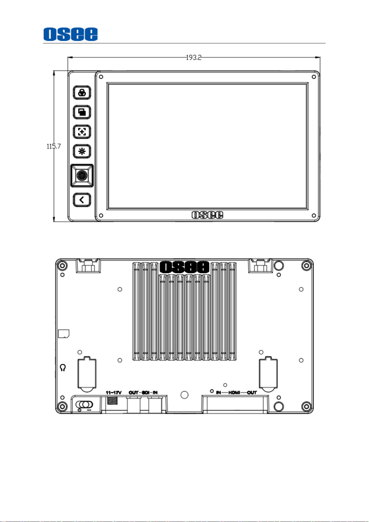
6.3 Dimensions
The description of the HCM-700 dimensions are as shown in the following
figures(Unit: mm):
66
Page 73
Specifications
Figure 6.3-1 Front View(Unit: mm)
Figure 6.3-2 Back View(Unit: mm)
67
Page 74

Specifications
Figure 6.3-3 Side View(Unit: mm)
Figure 6.3-4 Top View (Unit: mm)
Specifications are subject to change without notice.
------------------No Text Below------------------
68
Page 75

OSEE TECHNOLOGY LTD.
Address:
No.22 Building, No.68 zone, Beiqing Road, Haidian District,
Beijing, China
Tel:
(+86) 010-62434168
Fax:
(+86) 010-62434169
FOR MORE INFORMATION PLEASE VISIT: http://www.osee-dig.com.cn/
FOR MORE INFORMATION PLEASE VISIT: http:/www.oseeamericas.com
OSEE AMERICAS, LTD.
Address: 43218 Christy Street Fremont, CA. 94538
Tel: (+1) 510-996-4499
E-mail: [email protected]
 Loading...