

Page 1

HCC6830N Series
HD/SD Digital Video Signal
Cross Converter
User Manual
Page 2

Page 3

3
Product Information
Model:
HCC6830N Series HD/SD Digital Video Signal Cross Converter
Version:
V010001
Release Date:
August 21th, 201
Company
OSEE TECHNOLOGY CO., LTD.
Contact Information
Address:
No.22 Building, No.68 zone, Beiqing Road, Haidian District,
Beijing, China
Post Code:
100094
Tel:
(+86) 010-62434168
Fax:
(+86) 010-62434169
Web:
http://www.osee-dig.com/
E-mail:
Page 4
About this manual
Important
The following symbols are used in this manual:
The further information or know-how for described subjects above which
helps user to understand them better.
The safety matters or operations that user must pay attention to when using
this product.
Contents
The user manual applies to the following device types:
HCC6830N
HCC6830NS
The images of HCC6830Nare adopted in the following descriptions.
Any of the different specifications between the device types are elaborated.
Before reading the manual, please confirm the device type.
Page 5

Contents
Contents .......................................................................................................... I
Chapter 1 Product Overview ......................................................................... 1
Chapter 2 Safety ............................................................................................. 5
Chapter 3 Unpack and Installation ............................................................... 7
Chapter 4 Features ...................................................................................... 13
4.1
Front Panel Features ........................................................................ 13
4.2
Rear Panel Features .......................................................................... 14
Chapter 5 Operation and Control ............................................................... 17
5.1
Instructions on Control and Operation ........................................... 17
5.2
Instructions on Parameter Settings ................................................. 18
5.2.1
Parameter Settings ......................................................................... 18
5.2.2
Menu Items ..................................................................................... 19
5.3
LED Indicator ..................................................................................... 21
5.4
HDMI Input/Output Module ............................................................... 23
5.4.1
Installation ...................................................................................... 23
5.4.2
Network Control .............................................................................. 24
Chapter 6 Specifications ............................................................................. 27
Chapter 7 Appendix ..................................................................................... 31
7.1
AFD in 4:3 Mode ................................................................................ 31
7.2
AFD in 16:9 Mode .............................................................................. 32
7.3
Converting from 4:3 to 16:9.............................................................. 33
7.4
Converting from 16:9 to 4:3.............................................................. 35
Page 6

Page 7
Product Overview
1
Chapter 1 Product Overview
This article is mainly about HCC6830N series models, which are HD/SD digital
signal cross converter that can be installed in 6800N series frame.
HCC6830N series models are high- integrated, they are the platform for
synchronizing and converting between HD and SD signals, and processing HD
and SD signals to mixed signals. They support signal cross converting and
AFD control. They use the advanced dynamic interlace analysis technology to
achieve high-quality video, and achieve the converting among various formats
video signals.
HCC6830N Series HD/SD Digital Video Signal Cross Converter support one
HDMI input, two SD-SDI output which have been cross converted and one
video loop output with clock recovery.
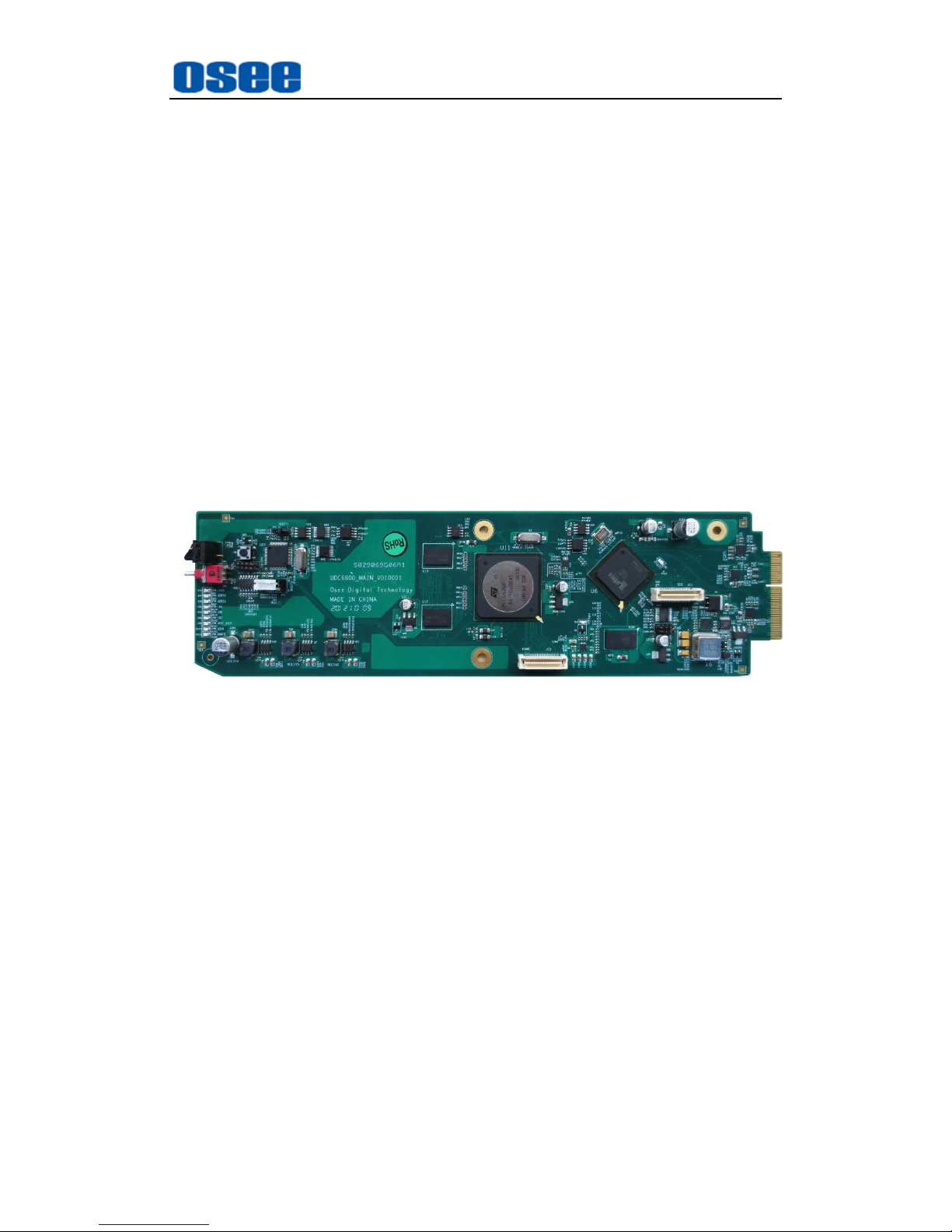
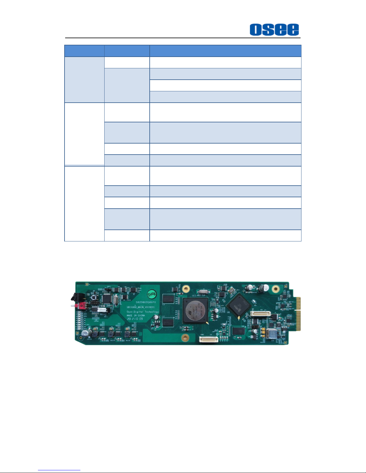
Figure 1-1 The Module of HCC6830N/HCC6830NS
HCC6830N/ HCC6830NS models support the following features:
Features
synchronous frame and cross conversion (only HCC6830NS has this
feature)
converting HD/SD-SDI input signals
using the advanced dynamic interlace analysis technology to achieve
high-quality video
ARC: automatic, using AFD(SMPTE-2016)
build-in framelock function and adjustment (only HCC6830NS model
has the framelock function)
build-in black field signal generator
build-in color corrector
Functionality
Page 8
Product Overview
2
process or convert the auxiliary data, such as CC(608/708) and time
code (LTC、VITC)
alarm when video lost, static frame or detecting black field
supports SNMP for native and remote users to configure models
GPIO used to pre-set and parameter selection
Product Model
Table 1-1 Introduction of HCC6830N/ HCC6830N
Model Type
Description
HCC6830N
HCC6830N Series HD/SD Digital Video Signal Cross Converter,
supports HD/SD-SDI/HDMI.
HCC6830NS
HCC6830N Series HD/SD Digital Video Signal Cross Converter,
supports HD/SD-SDI/HDMI and frame synchronization.
The HCC6830N series models will support 3G video signals after
upgrading by getting the authorization code which is as a selection. Using
the authorization code to upgrade the module by WEB.
The HCC6830N series models will support one HDMI output by mounting a
HDMI input/output module as a selection.
Page 9
Product Overview
3
Table 1-2 Input/Output Signals Supported by HCC6830N/ HCC6830NS
Model Type
Input
Output
HCC6830N
one adaptive HD/SD-SDI video
input
one HDMI input(achieved when
selecting HDMI input&output
module)
two HD-SDI output of cross
converted
Video loop output with clock
recovery
one HDMI output(achieved when
selecting HDMI input&output
module)
HCC6830NS
one adaptive HD/SD-SDI video
input
one HDMI input (achieved when
selecting HDMI input&output
module)
two HD-SDI output of cross
converted with synchronous frame
Video loop output with clock
recovery
one HDMI output (achieved when
selecting HDMI input&output
module)
Signal Flow Chart
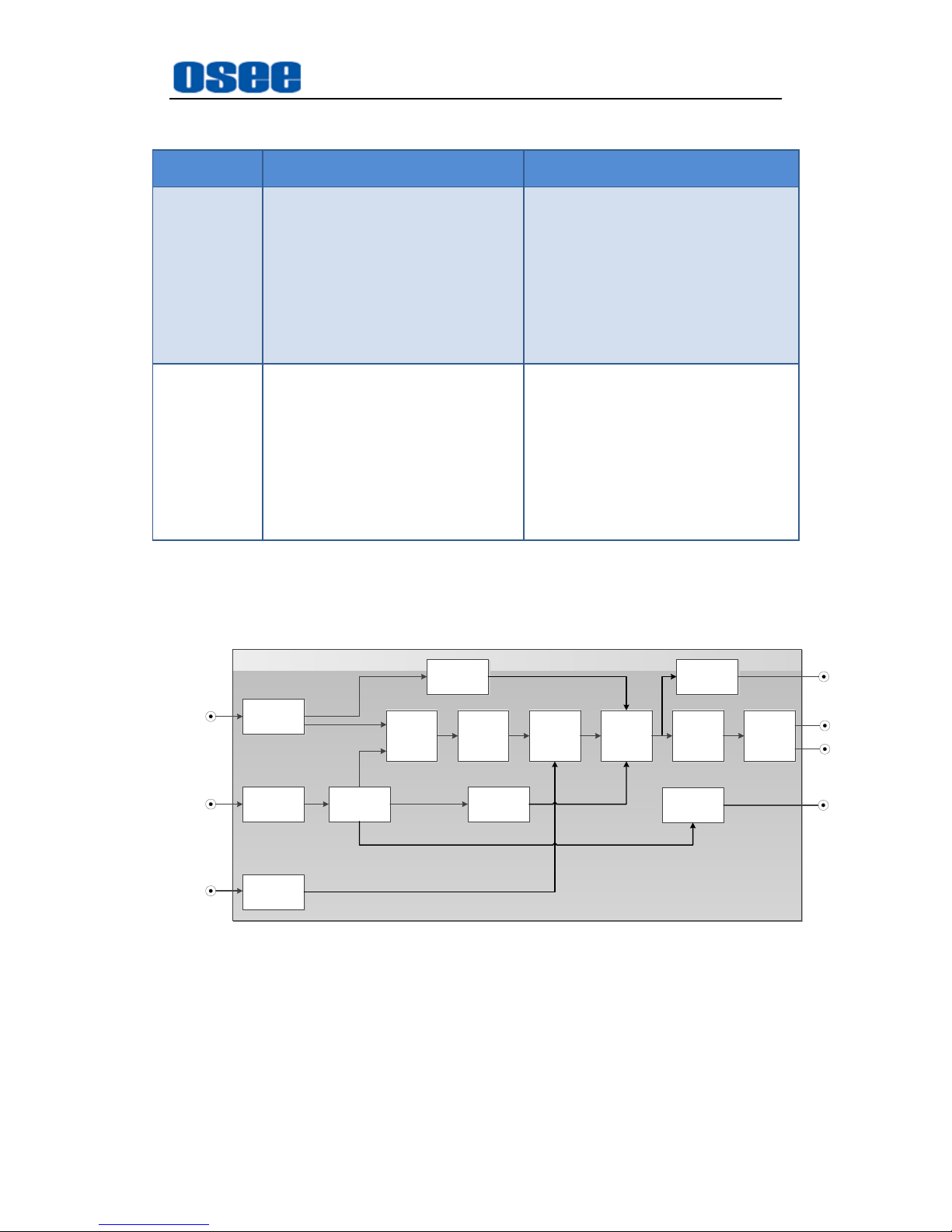
The signal flow chart for this unit is shown as in Figure 1-2:
HDMI
Receiver
HDMI IN
Video
Scaler
Color
Space
Conver
Generate
MUX
AUDIO
ANC
MUX
SDI
Trans
SDI
Driver
Audio SIP
HDMI
Trans
EQ
SDI
Receiver
Genlock
Audio anc
demux
Loop out
SDI IN
REF IN
HDMI OUT
SDI OUT
SDI OUT
SDI OUT
Figure 1-2 The Signal Flow Chart of HCC6830N/HCC6830NS
Page 10

4
Page 11

Safety
5
Chapter 2 Safety
FCC Caution:
Any Changes or modifications not expressly approved by the party responsible
for compliance could void the user's authority to operate the equipment.
This device complies with part 15 of the FCC Rules.
Operation is subject to the following two conditions: (1) This device may not
cause harmful interference, and (2) this device must accept any interference
received, including interference that may cause undesired operation.
Note: This equipment has been tested and found to comply with the limits for a
Class B digital device, pursuant to part 15 of the FCC Rules. These limits are
designed to provide reasonable protection against harmful interference in a
residential installation. This equipment generates uses and can radiate radio
frequency energy and, if not installed and used in accordance with the
instructions, may cause harmful interference to radio communications.
However, there is no guarantee that interference will not occur in a particular
installation. If this equipment does cause harmful interference to radio or
television reception, which can be determined by turning the equipment off and
on, the user is encouraged to try to correct the interference by one or more of
the following measures:
Reorient or relocate the receiving antenna.
Increase the separation between the equipment and receiver.
Connect the equipment into an outlet on a circuit different from that to which
the receiver is connected.
Consult the dealer or an experienced radio/TV technician for help.
Page 12
Safety
6
Warnings:
Read, keep and follow all of these instructions for your safety. Heed all
warnings.
Converter
Upgrading of the converter is subject to change without notice.。
Contact your Customer Service representative if parts are missing or
damaged.
Position
Do not block any ventilation openings.
Do not use this unit near water.
Do not expose the unit to rain or moisture.
Do not install near any heat sources such as radiators, heat registers,
stoves, or other apparatus (including amplifiers) that product heat.
A nameplate indicating operating voltage, etc., is located on the rear
panel.
The socket-outlet shall be installed near the equipment and shall be
easily accessible.
Page 13
Unpack and Installation
7
Chapter 3 Unpack and Installation
Unpack
When unpacking the components of this converter, please verify that none of
the components listed in Table 3-1 are damaged or lack. If there is any missing,
contact your distributors or OSEE for it.
Table 3-1 Packing List
No.
Item
Quantity
Comments
1
Converter
1
HCC6830N/HCC6830NS
2
Interface board
1
3
Attachments
1
4 User manual
1
5 warranty card
1
About Unpacking and Shipping
This product was carefully inspected, tested, and calibrated before
shipment to ensure years of stable and trouble-free service. Before
you install this unit, do the followings:
Check the equipment for any visible damage that may have
occurred during transit.
Confirm receipt of all items on the packing list.
Contact your dealer if any item on the packing list is missing.
Contact the carrier if any item is damaged.
Remove all packaging material from the product before you install
the unit.
Retain at least one set of the original packaging materials, in the
event that you need to return a product for servicing.
Page 14

Unpack and Installation
8
If the original package is not available, you can supply your own
packaging as long as it meets the following criteria:
The packaging must be able to withstand the product’s weight.
The product must be held rigid within the packaging
There must be at least 5 cm of space between the product and the
container.
The corners of the product must be protected.
Ship products back to us for servicing prepaid and, if possible, in the
original packaging material. If the product is still within the warranty
period, we will return the product prepaid after servicing.
Installation
1. Prepare for installation
Make sure you have prepared the followings before mount the converter:
Inspect for any apparent physical damage that may have occurred in
transit.
Make sure you have received all the components listed in packing list.
if there are any anti-static package or other packages, please take off
them.
Keep the package in case of future usage.
The safety matters or operations that user must pay attention to when using
this product.
Check out the consumption of model and the maximum power of frame
before installation, The maximum power ratings for different frames are
shown as in Table 3-2.
Ensure that all handling precautions are taken to avoid electrostatic
discharge or other damage to sensitive electronic components. Wear an
earth strap and perform all PCB assembly at an appropriate anti-static work
Page 15
Unpack and Installation
9
station. Follow the instructions carefully to fit the models.
Table 3-2 Maximum Power Ratings for 6800N Series Frames
Frame
Maximum Voltage
Redundant Power
Supplies
Numbers of Slots
6800N-C1
40W
Yes
4
6800N-C2
60W
Yes
10
2. Install the module
Follow the following steps to install the module:
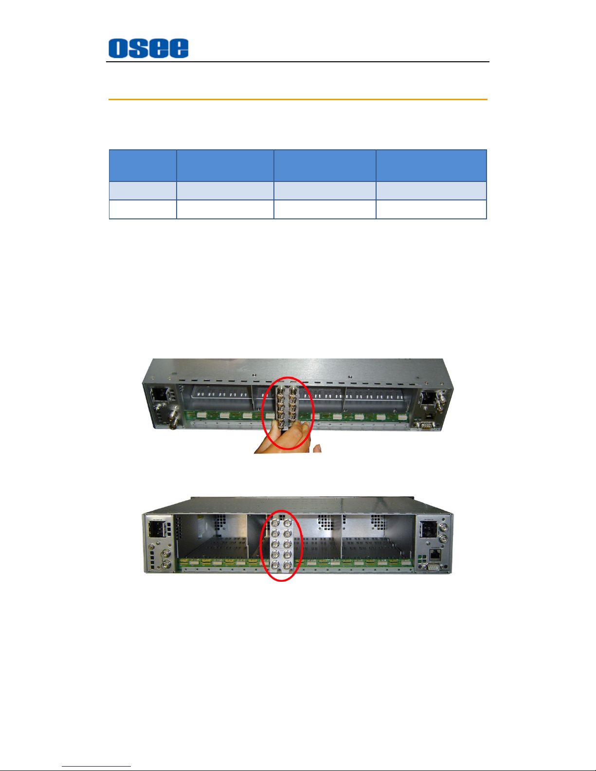
Step 1 Install a back connector
First, install the back connector at the rear of the frame. Locate the
position for back connector and insert the back connector along the
slot, as shown in Figure 3-1 and Figure 3-2.
Figure 3-1 Rear Panel-Insert the Back Connector
Figure 3-2 Rear Panel-Fix the Back Connector
Page 16
Unpack and Installation
10
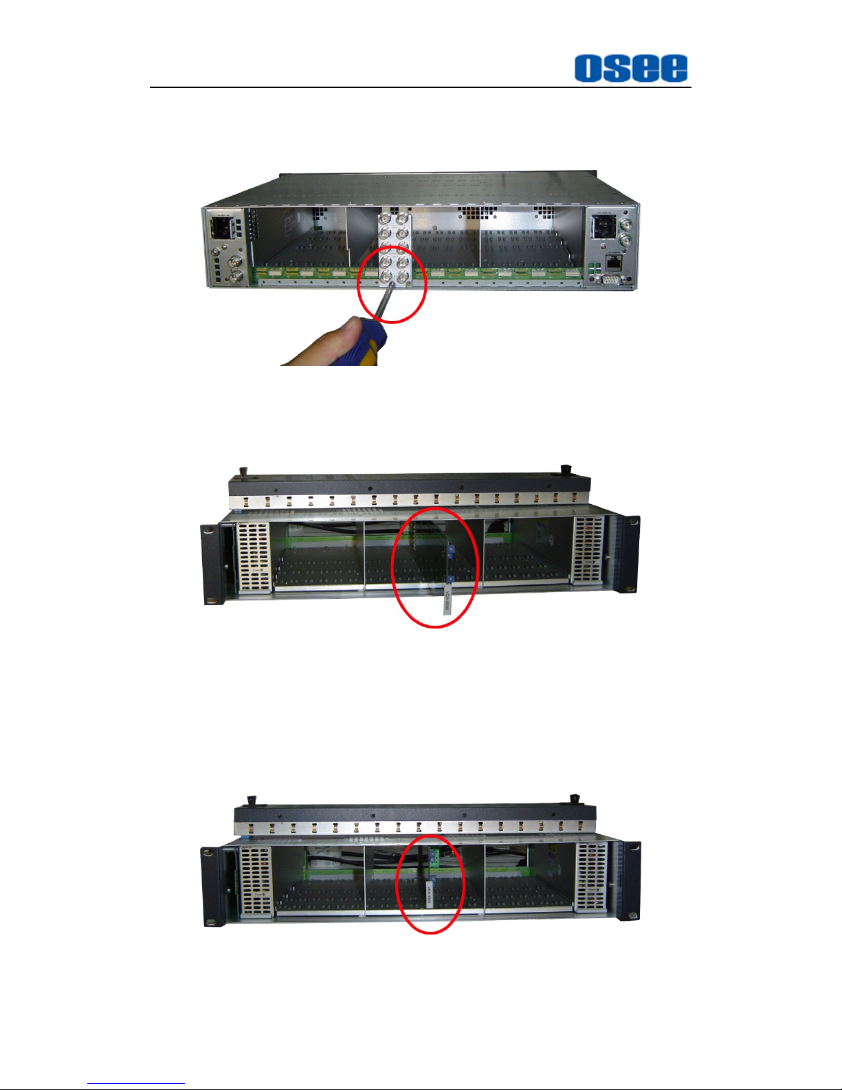
Step 2 Fasten the screw to fix the back connector, as shown in Figure
3-3.
Figure 3-3 Rear Panel-Fasten the Back Connector
Step 3 Locate the slot for module, as shown in Figure 3-4.
Figure 3-4 Front Panel-Push the Module into the Slot
Step 4 Get the module installed in the slot.
Then, push the module slightly along the slot, press module again
to confirm that the module is installed firmly and then close swivel
handle, as shown in Figure 3-5.
Figure 3-5 Front Panel-Close the Swivel Handle of the Module
Page 17
Unpack and Installation
11
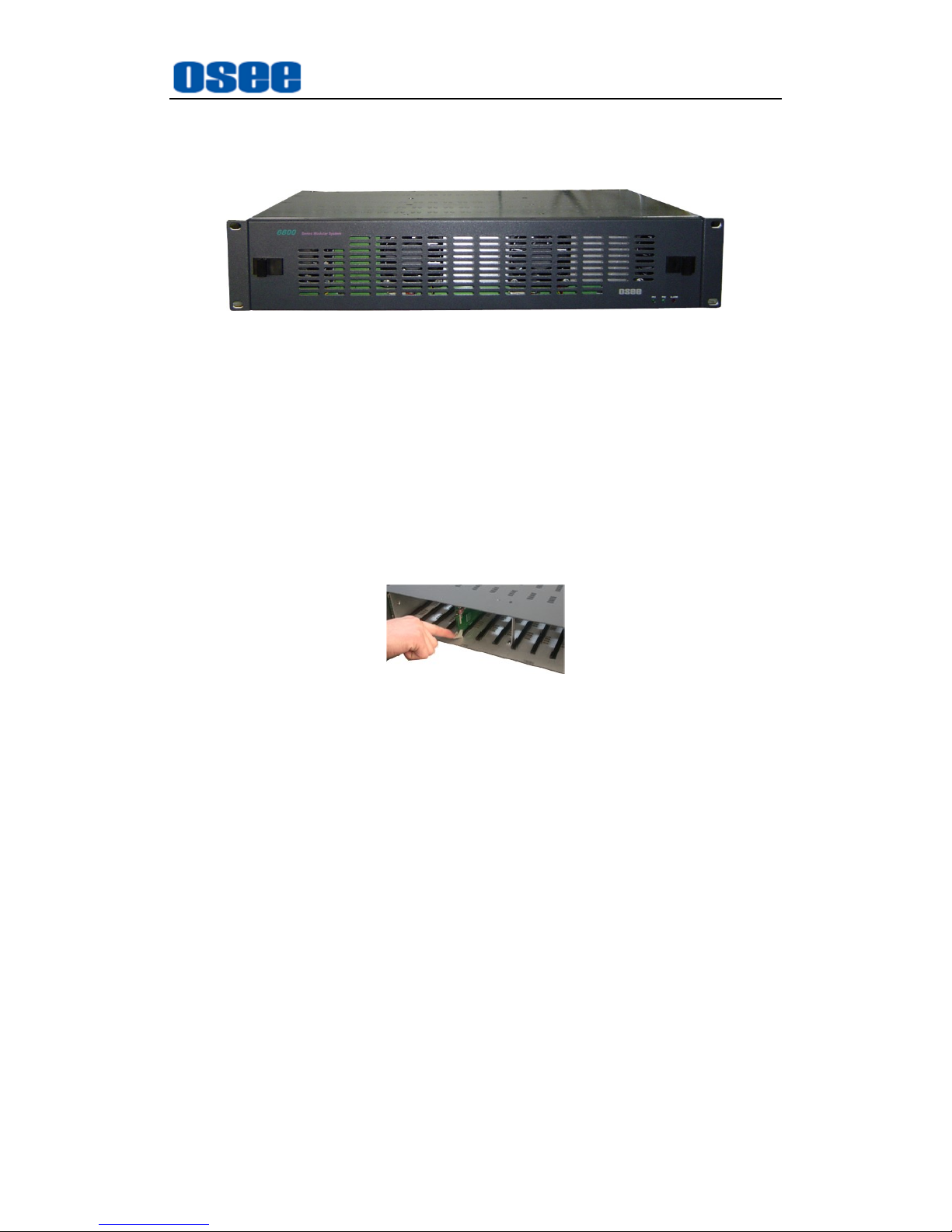
Step 5 Install the front panel.
At last, install the front panel of the frame, as shown in Figure 3-6.
Figure 3-6 Front Panel-Install the Front Panle
Uninstallation
Follow the following steps to remove the module:
Step 1 Remove the front panel of the frame.
Step 2 Loosen and take off the module
Press down the swivel handle to loosen the module, as shown in
Figure 3-7.
Figure 3-7 Press Down the Swivel Handle
Then, hold the swivel handle, and pull out the module along the slot
of the frame.
Step 3 Install the front panel.
Take off the module, and mount the front panel on the frame.
Step 4 Take off the back connector
Unscrew the screws of the back connector, and take off the back
connector.
Page 18

12
Page 19
Features
13
Chapter 4 Features
4.1 Front Panel Features
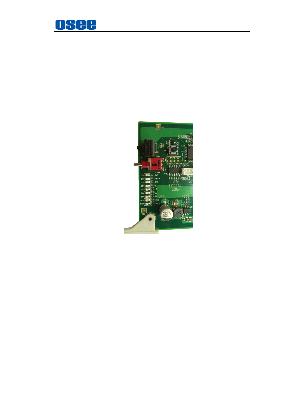
The control switches and the LED indicator lights of HCC6830N series
modules are shown as in Figure 4-1:
1
2
3
Figure 4-1 The Switches and LED Lights of HCC6830N/HCC6830NS
1. Rotary switch
It is a rotary switch which has 16 positions coded from 0 to F, it is used to
select and point to a parameter item.
2. Toggle switch
It is a toggle switch which has 3 positions which will get back to the middle
position automatically, It is used to set the parameter value which has
been selected by SW1 through toggling up or down the handle.
3. LED Indicator
It shows the basic information of the module, refer to “5.3 LED Indicator”
for details.
Refer to “Chapter 5 Operation and Control” for the operation instructions of the
switches and LED indicators.
Page 20
Features
14
4.2 Rear Panel Features
1. Illustration for back connector
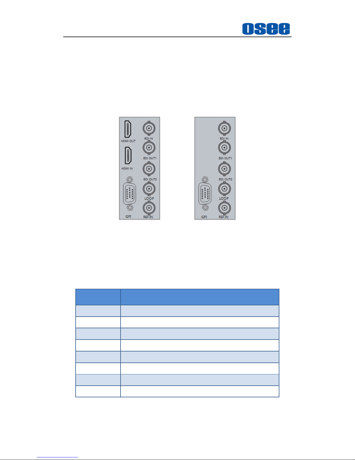
We provide a HDMI input&output module to support HDMI input and
output function for HCC6830N/ HCC6830NS module. There are two kinds
of back connector for this function, the back connectors are shown as in
Figure 4-2:
Figure 4-2 The Back Connector of HCC6830N/HCC6830NS
The interfaces on the back connector of HCC6830N/HCC6830NS are
shown as Table 4-1:
Table 4-1 The interfaces on the Back Connector
Interface
Description
HDMI OUT
HDMI output
HDMI IN
HDMI input
SDI IN
HD/SD-SDI input
SDI OUT 1
HD/SD-SDI output 1
SDI OUT 2
HD/SD-SDI output 2
LOOP
Video loop output with clock recovery
REF IN
Reference input(only HCC6830NS has this interface)
GPI
Reserved
Page 21
Features
15
2. Illustration for back panel
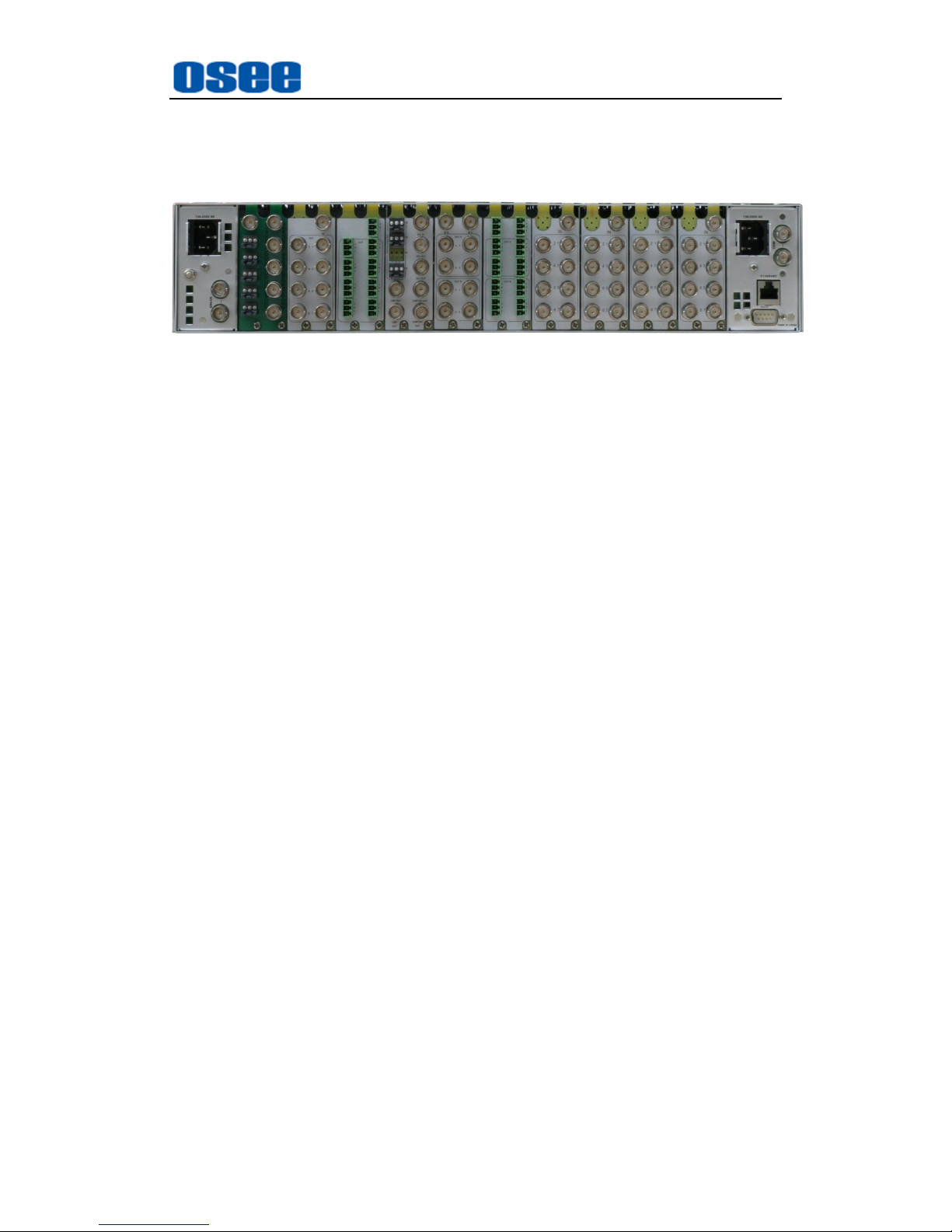
After mounting various back connectors to the frame, they are shown as in
Figure 4-3:
Figure 4-3 The Back Connector of a Frame
Page 22

16
Page 23

Operation and Control
17
Chapter 5 Operation and Control
This chapter describes the main functionality and working mode of
HCC6830N/HCC6830NS.
5.1 Instructions on Control and Operation
The control switches are at the edge of the module, as shown in
Figure 5-1:
SW1
SW1
SW2
SW2
Figure 5-1 The Position of Control Switches
The function and usage of the switch are as follows:
1. SW1: It is a rotary switch which has 16 positions coded from 0 to F, it is
used to select and point to a parameter item. The selection range is: 0, 1,
2, 3, 4, 5, 6, 7, 8, 9, A, B, C, D, E, F.
0
1
2
3
4
5
6
7
8
9
A
B
C
D
E
F
0
Figure 5-2 Rotary Switch Pointing at 0
For example: as shown in Figure 5-2, the pointer is pointing at the
position 0, that is Bank Select as shown in Table 5-1.
Page 24
Operation and Control
18
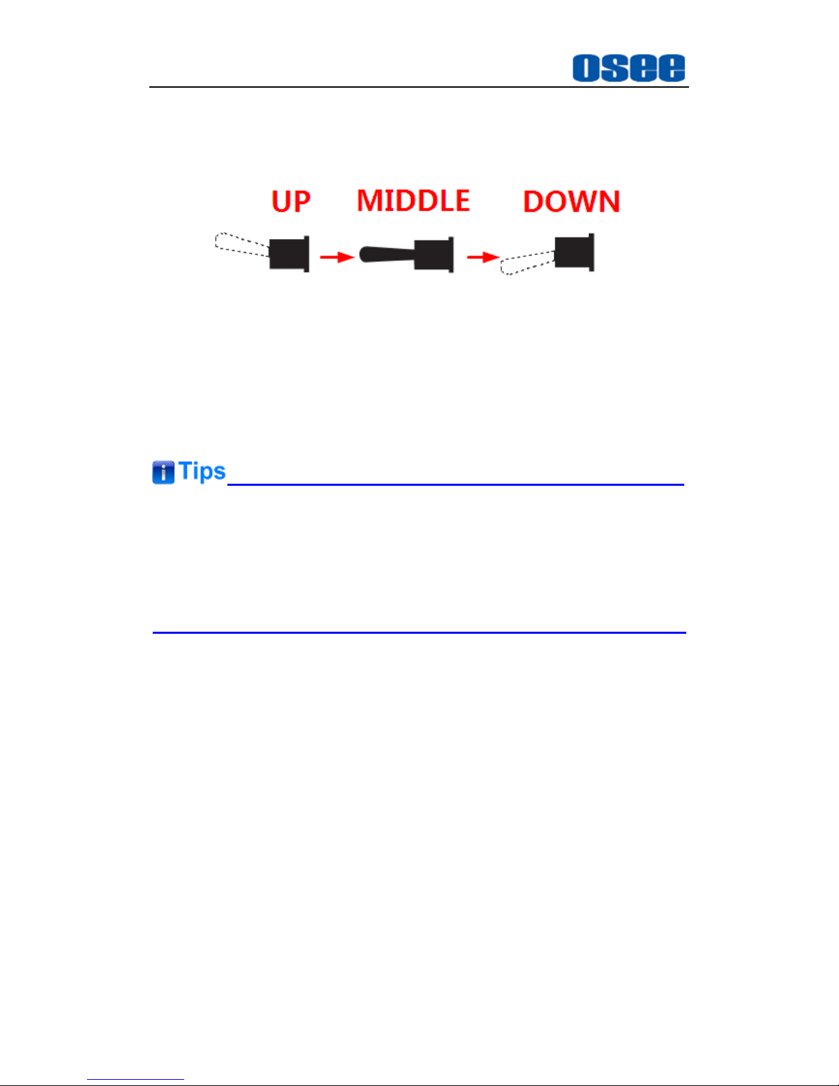
2. SW2: It is a toggle switch which has 3 positions which will get back to the
middle position automatically, It is used to set the parameter value which
has been selected by SW1 through toggling up or down the handle.
Figure 5-3 Toggle Switch Moving Up And Down
For example: as shown in Figure 5-3, there are three positions of
SW2, but the handle will always be back to the middle position
automatically after toggling it up or down. After you switching SW1
to a parameter item, toggle SW2 up or down to set the parameter
value.
When setting parameters, the LED indicators will indicate the status of the
module.
SW1 identifies the rotary switch, and SW2 identifies the toggle switch in this
article.
5.2 Instructions on Parameter Settings
It will introduce how to set the parameters and the meanings of LED indicators
in the followings.
5.2.1 Parameter Settings
HCC6830N/HCC6830NS module has three Banks, they are Bank0,
Bank1 and Bank2, each Bank is divided into 16 menu items, and each
menu item has a parameter value or a status. Set up these items to
control the module or check its status.
You can judge whether you have selected a Bank by DBS0 LED indicator
at the edge of the module, refer to Table 5-4 for details.
Do as the following instructions:
Page 25
Operation and Control
19
Switch SW1 to position 0, and toggle SW2 to select a proper Bank
Toggle SW2 up until you select BANK 0, and toggle SW2 down until
you select BANK 2.
Then, switch SW1 to a menu item, and cooperate with SW2 to set its
value.
The position 0 of every Bank is always used to select Bank, that is
whichever Bank it is, as long as you switch SW1 to position 0, toggle SW2
to select a Bank.
5.2.2 Menu Items
The functions and value range of each Bank menu items are as shown in
Table 5-1, Table 5-2 and Table 5-3.
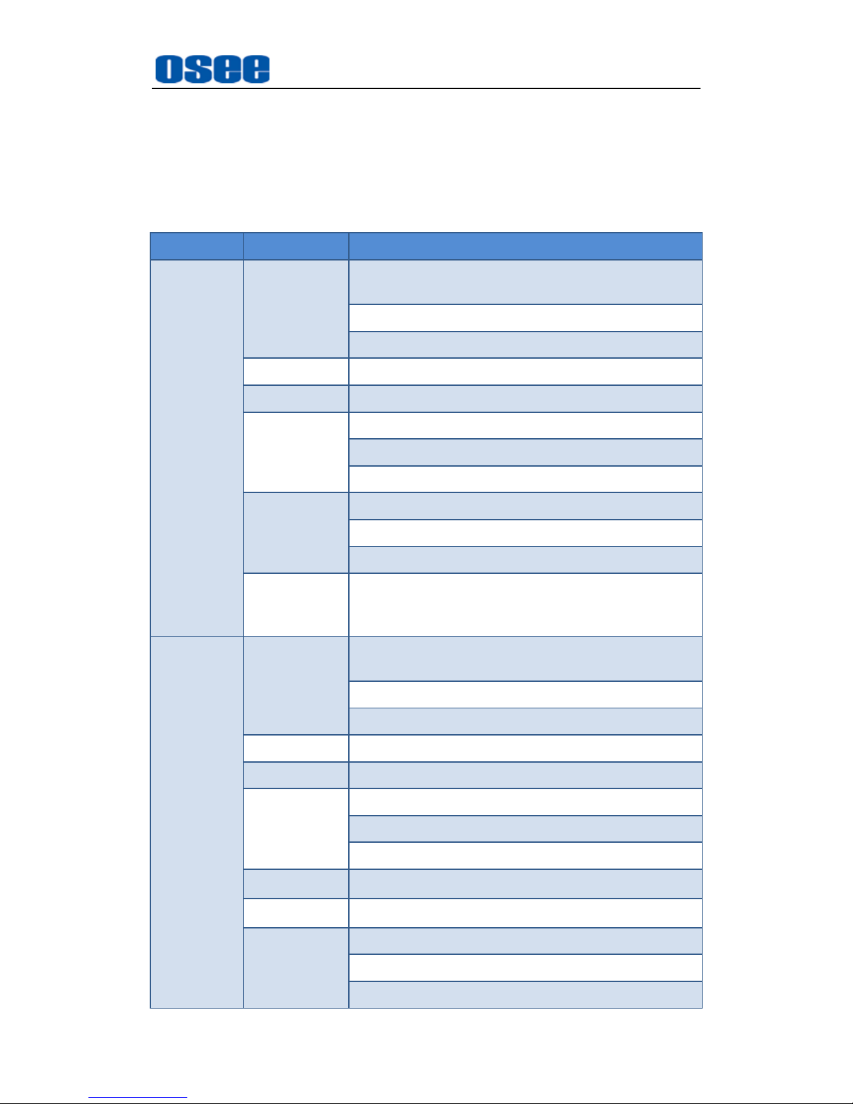
Table 5-1 SW1 Function Settings of Bank 0
SW1
Position
Function
Value
Default
0
Bank Select
Bank0, Bank1, Bank 2
Bank 0
1~2
RED GAIN SDI/HDMI
0~512
128
3~4
GREEN GAIN SDI/HDMI
0~512
128
5~6
BLUE GAIN SDI/HDMI
0~512
128
7
RED BIAS SDI
0~128
0 8 RED BIAS HDMI
0~128
0 9 BLUE BIAS SDI
0~128
0 A BLUE BIAS HDMI
0~128
0 B GREEN BIAS SDI
0~128
0 C GREEN BIAS HDMI
0~128
0
D
CONTRAST SDI
0~100
50 E CONTRAST HDMI
0~100
50 F BRIGHT SDI
0~100
50
Table 5-2 SW1 Function Settings of Bank 1
Page 26
Operation and Control
20
SW1
Position
Function
Value
Default
0
Bank Select
Bank0, Bank1, Bank 2
Bank 0
1
BRIGHT HDMI
0~100
50 2 CHROMA SDI
0~100
50 3 CHROMA HDMI
0~100
50 4 SHARPNESS
0~100
50
5~F
Reserved
-
-
Table 5-3 SW1 Function Settings of Bank 2
SW1
Position
Function
Value
Default
0
Bank Select
Bank0, Bank1, Bank 2
Bank 0
1
SDI output synchronous
selection
Normal; fs
Normal
2
SDI output format*1
525I60; 625I50;
720P60; 720P59;
720P50; 1080I60;
1080I59; 1080I50;
1080P60; 1080P59;
1080P50; 1080P30;
1080P29; 1080P25;
1080P24; 1080P23;
1080SF24
-
3
Mode selection
SDI; HDMI
SDI
4
Output phase shifting*1
525I60:0~1716
625I50:0~1728
720P60:0~1650
720P59:0~1650
720P50:0~1980
1080I60:0~2200
1080I59:0~2200
1080I50:0~2640
1080P24:0~2750
1080P23:0~2750
1080P25:0~2640
1080P30:0~2200
1080P29:0~2200
-
Page 27
Operation and Control
21
SW1
Position
Function
Value
Default
1080P60:0~2200
1080P59:0~2200
1080P50:0~2640
5
Output phase shifting*1
525I60:0~525
625I50:0~625
720P60:0~750
720P59:0~750
720P50:0~750
1080I60:0~1125
1080I59:0~1125
1080I50:0~1125
1080P24:0~1125
1080P23:0~1125
1080P25:0~1125
1080P30:0~1125
1080P29:0~1125
1080P60:0~1125
1080P59:0~1125
1080P50:0~1125
-
6
Black field output
Normal; Black
Normal
7
AFD input mode
Auto; Manual
Auto
8
AFD output mode
Auto; Manual
Auto
9
AFD input
Manual Range:0~15
- A AFD output
Manual Range:0~15
-
B
Synchronous mode
analog sync;
tri level sync signal
analog
sync
C~E
Reserved
-
-
F
Factory Default
no operation;
factory recall
no
operation
Notes: *1 is the customized setting.
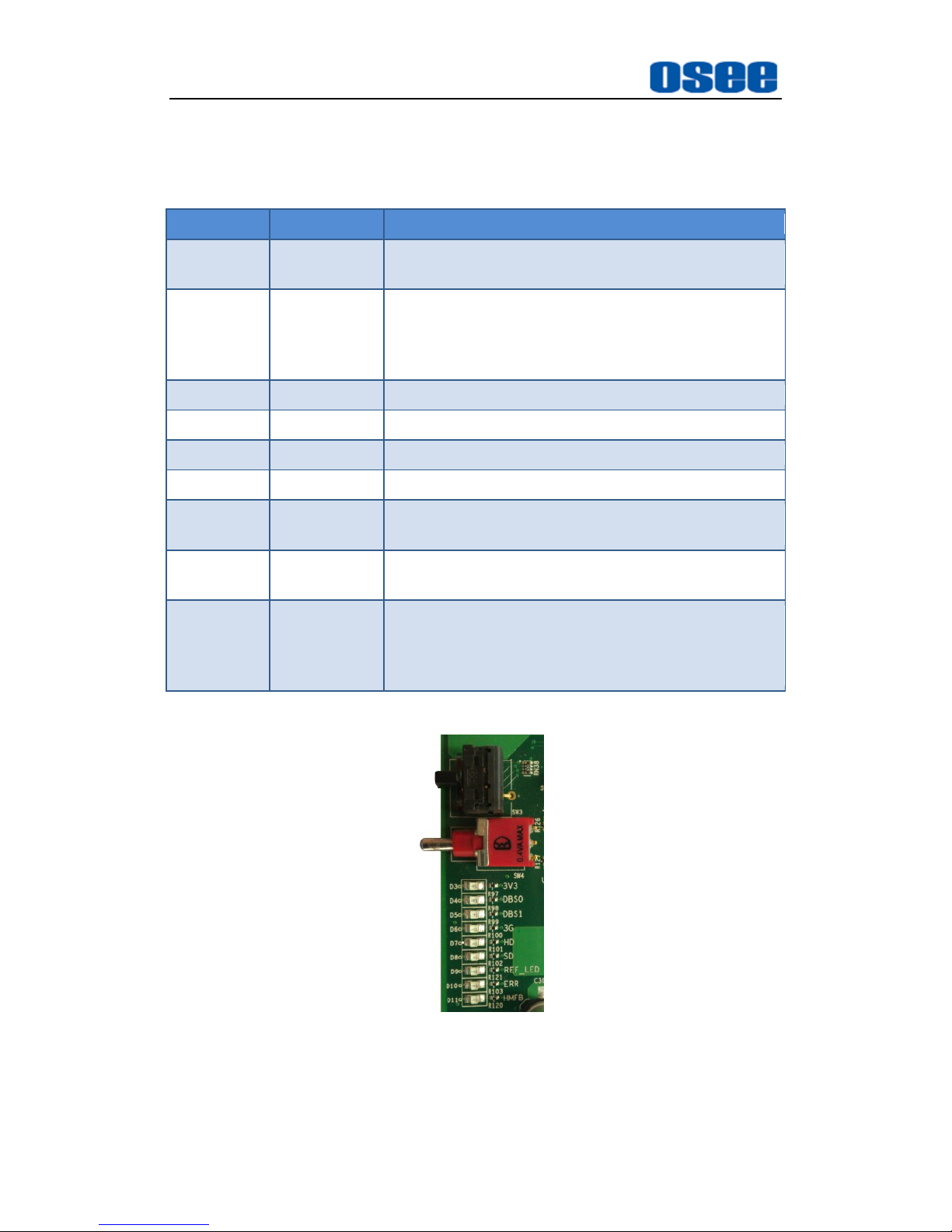
5.3 LED Indicator
The LED indicators show different color when expressing different meanings,
as shown in Table 5-4. You can fix the position of LED indicator by logo printing
Page 28
Operation and Control
22
on the module, as shown in Figure 5-4
Table 5-4 The Functionality of Each LED Indictor
Indicator
Color
Description
3V3
Green
Power indicator.
On: power is normal; Off: power is abnormal.
DBS0
Orange
It indicates which Bank you have selected.
If it is in BANK0 state, both DBS0 and DBS01 are
all off. If it is in BANK1 state, DBS0 is on, and if in
BANK2 state, DBS1 is on.
DBS1
Orange
It indicates whether in BANK2 state.
3G
Green
If LED is on, it indicates that is 3G input signal.
HD
Green
If LED is on, it indicates that is HD input signal.
SD
Green
If LED is on, it indicates that is SD input signal.
REF_LED
Green
If LED is on, it indicates that is the reference signal
is locked (only for HCC6830NS).
ERR
Green
If LED is on, it indicates there is EDH error or CRC
error in input signal.
HMFB
Green
If LED is on, it indicates that this module is working
with HDMI input/output module;
If LED is off, it indicates that this module is in SDI
working mode.
Figure 5-4 The Logo Printing of LED Indicator
Page 29
Operation and Control
23
5.4 HDMI Input/Output Module
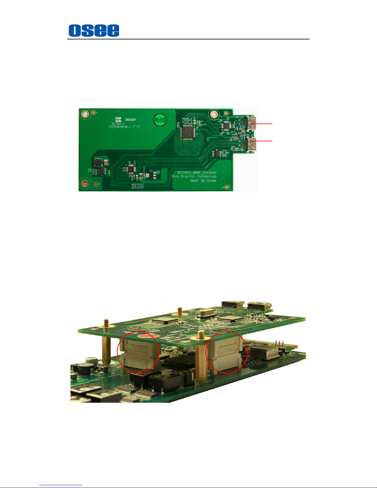
Add a HDMI Input/Output module( as shown in Figure 5-5) to HCC6830N/
HCC6830NS module to achieve the HDMI input and output function.
HDMI
OUTPUT
HDMI
INPUT
Figure 5-5 HDMI Input/Output Module
5.4.1 Installation
Follow the instructions below to install a HDMI Input/Output module:
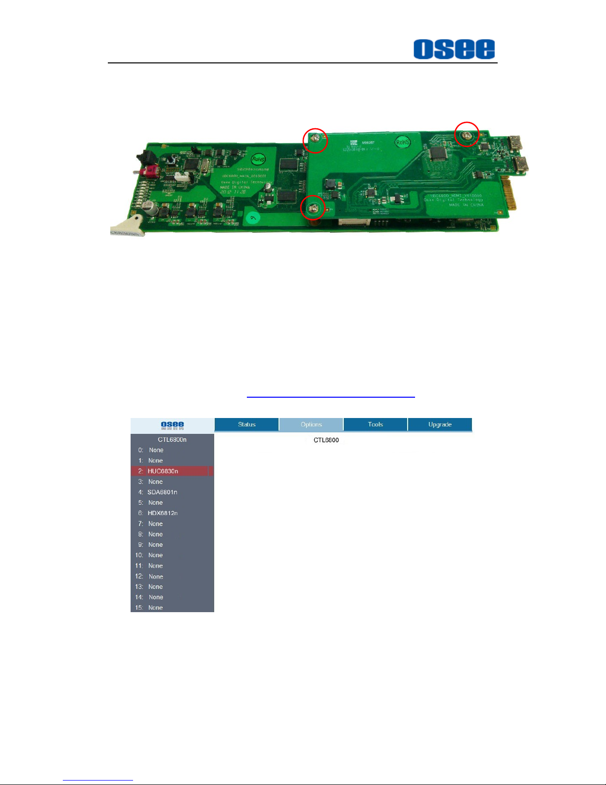
Step 5 Connect the module blug
The red circles in Figure 5-6 identify the connection state of male
plug and female plug.
Figure 5-6 Side View- Installing a HDMI Input/Output Module
Page 30
Operation and Control
24
Step 6 Fasten the screws
The red circles in Figure 5-7 identify the screws after fastened.
Figure 5-7 Front View-Installing a HDMI Input/Output Module
5.4.2 Network Control
Install the HCC6830N/ HCC6830NS module into 6800N series frame, it
will support upgrade the module by network.
Open a web page through the IP address which 6800-FC module
specified, for example: http://192.168.1.33/web/index.htm, the web page
is shown as in Figure 5-8:
Figure 5-8 The Network Control Interface
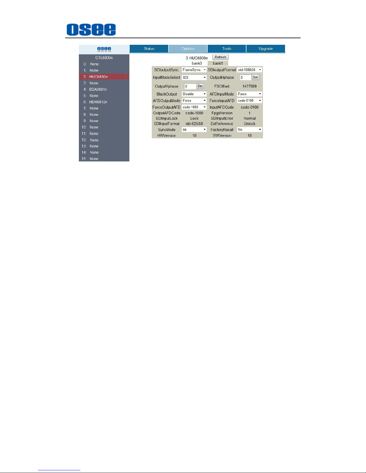
Click Options tab to set the menu items used in HCC6830N/ HCC6830NS,
as shown in Figure 5-9:
Page 31
Operation and Control
25
Figure 5-9 The Options in the Network Control Interface
You can customize the IP address in the corresponding item in Tools tab,
and do upgrading operations in Upgrade tab, refer to "6800N network
control software user manual " for details.
Page 32

26
Page 33
Specifications
27
Chapter 6 Specifications
1. Product detailed information
Index
Specification
Values
Digital
Video Input
Video
Standard
SMPTE259m-C(270Mb/s,525/625 component)
SD-SDI
SMPTE292m(1.485,1.485/1.001Gb/s) HD-SDI
SMPTE424m(2.970,2.970/1.001Gb/s) 3G-SDI
Connector
BNC(IEC169-8)
Impedance
75Ω
Return Loss
>15dB,5MHz to 270MHz SD-SDI
>15dB,5MHz to 1485Hz HD-SDI
>15dB up to 3GHz 3G-SDI
Cable Length
SD-SDI:0~300mBelden1694A
HD-SDI: 0~100mBelden1694A
3G-SDI: 0~120mBelden1694A
Supported
Format
480i,576i,720p50,720p59.94,1080i50,1080i59.94,
1080p23.98,1080pSF23.98, 1080p25,
1080p29.97, 1080p50, 1080p59.94
Digital
Video
Output
Video
Standard
SMPTE259m-C(270Mb/s,525/625 component)
SD-SDI
SMPTE292m(1.485,1.485/1.001Gb/s) HD-SDI
SMPTE424m(2.970,2.970/1.001Gb/s) 3G-SDI
Connector
BNC(IEC169-8)
Impedance
75Ω
Return Loss
>15dB,5MHz to 270MHz SD-SDI
>15dB,5MHz to 1485Hz HD-SDI
>15dB up to 3GHz 3G-SDI
Output Level
800Mv±10%
DC Offset
0±0.5V
Rise and Fall
Time
400~1500 ps SD-SDI
<270 ps HD-SDI
<135 ps 3G-SDI
Page 34
Specifications
28
Index
Specification
Values
Overshoot
<10% of amplitude
Jitter
<0.2 UI pk-pk SD-SDI
<0.2 UI pk-pk HD-SDI
<0.3 UI pk-pk 3G-SDI
HDMI input
& output
Video
Standard
HDMI 1.3(CEA-861-B)2.25Gbps
Signal Format
480i、576i、720p50、720p59.94、1080i50
、
1080i59.94、1080p50、1080p59.94
Connector
HDMI
Cable Length
0~15m
Reference
Signal
Signal Format
analog composite synchronous signal and tri level
sync signal
Connector
BNC
Impedance
75Ω
Input Level
NTSC/PAL: 0.45V,-6dB~+6dB;
tri level sync signal: ±300mV, -6dB~+6dB
Return Loss
>35dB up to 5.75MHz
2. Product Outline
The outline of HCC6830N/HCC6830NS is shown as in the following
figures:
Figure 6-1 Top View
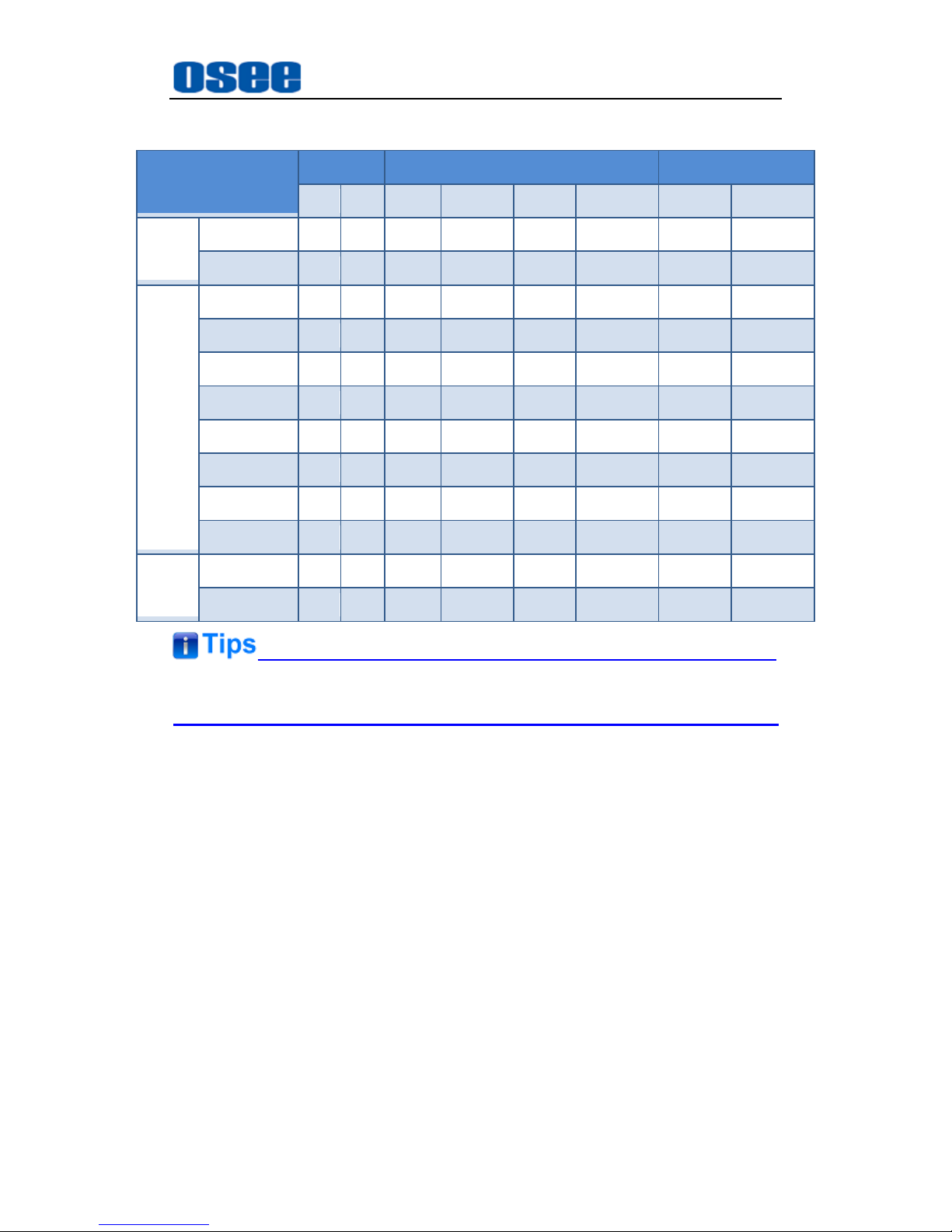
3. Supported Format Conversions
The HCC6830N/HCC6830NS series support the following compatible
formats.
Page 35
Specifications
29
Specifications are subject to change without notice.
Input Formats \
Output formats
SD HD 3G
525 625 720p50 720p59.94 1080i50 1080i59.94 1080p50 1080p59.94
SD
525
625
HD
720p50
720p59.94
1080i50
1080i59.94
1080p23.98
1080pSF23.98
1080p25
1080p29.97
3G
1080p50
1080p59.94
Page 36

30
Page 37
Appendix
31
Chapter 7 Appendix
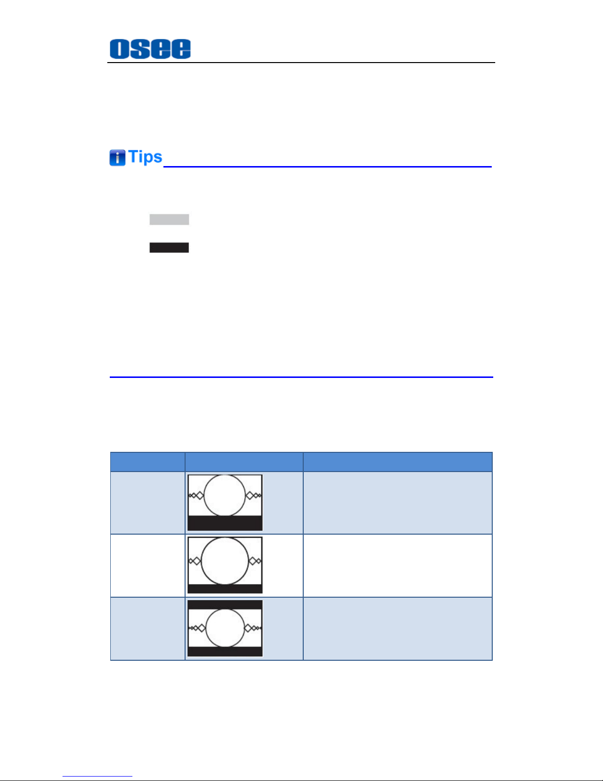
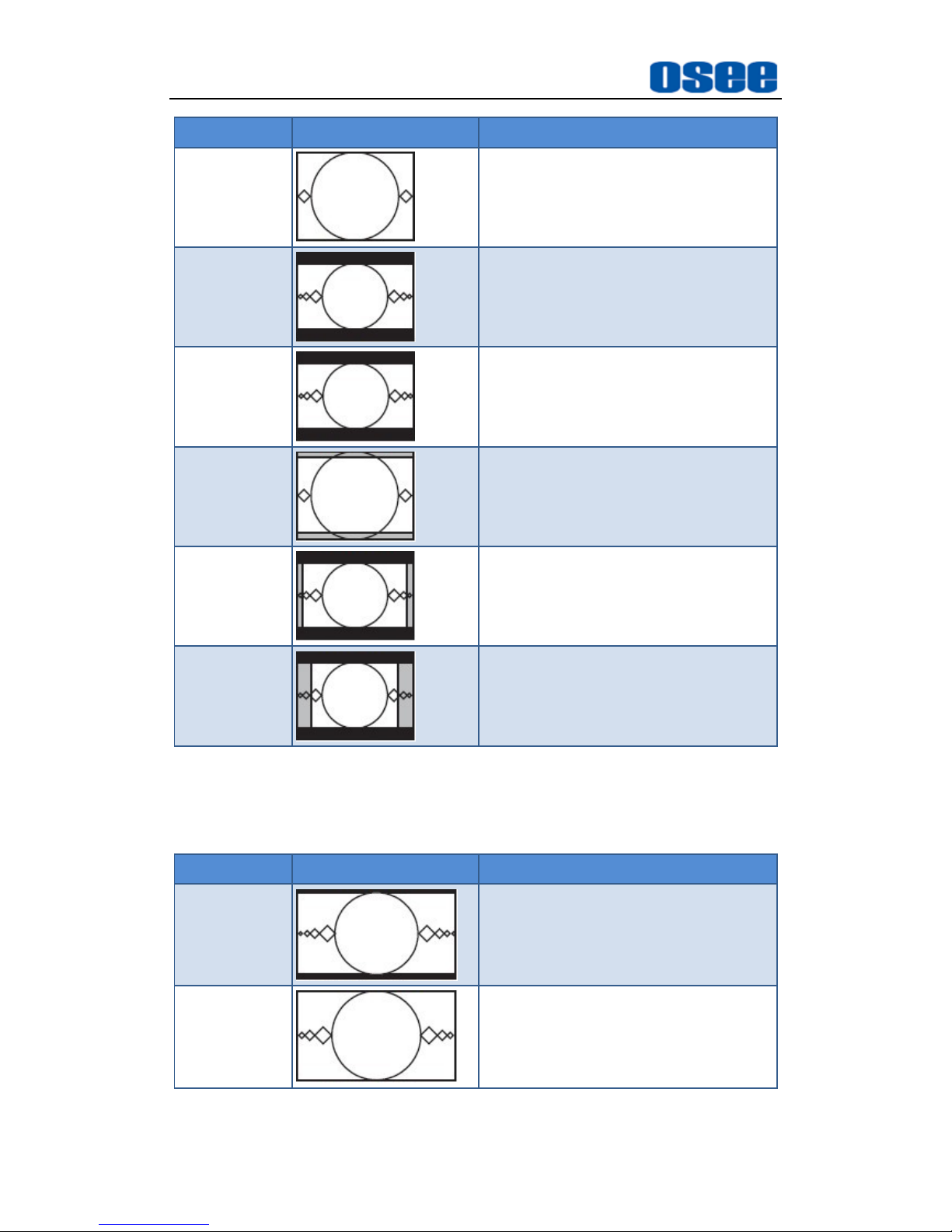
The icons used in this appendix are as follows:
: the cut area of an image
: add a black border
LetterBox: add a border at the top or bottom of an image
Pillarbox: add a border at the left side and right side of an image
Edge Crop: cut down the left side and right side of an image
Full Frame: cut down the top and bottom of an image
The automatic output converting will be invalid in manual mode.
7.1 AFD in 4:3 Mode
AFD Code
Illustrations
Description
0010
16:9 LetterBox at the top in a 4:3
Coded Frame
0011
14:9 LetterBox at the top in a 4:3
Coded Frame
0100
Aspect ratio greater than 16:9
LetterBox in a 4:3 Coded Frame
Page 38
Appendix
32
AFD Code
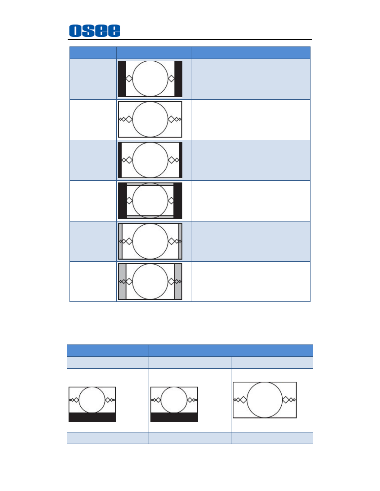
Illustrations
Description
1000
4:3 Full Frame
1010
16:9 LetterBox in 4:3 Coded Frame
1011
14:9 LetterBox,Centered, in 4:3
Coded Frame
1101
4:3 Centered at 14:9,4:3 Coded
Frame
1110
16:9 LetterBox,14:9 Alternative
Centered, in 4:3 Coded Frame
1111
16:9 LetterBox,4:3 Alternative
Centered, in 4:3 Coded Frame
7.2 AFD in 16:9 Mode
AFD Code
Illustrations
Description
0100
16:9 LetterBox with aspect ratio
greater than 16:9
1000
AFD Code:1000
16:9 Coded Full Frame
Page 39
Appendix
33
AFD Code
Illustrations
Description
1001
4:3 pillarbox
1010
16:9 Coded Full Frame with
Protected Area
1011
14:9 Centered image in a 16:9 Coded
Frame
1101
4: 3 with 14:9 Center
1110
16:9 with 14:9 Center
1111
16:9 with 4:3 Center
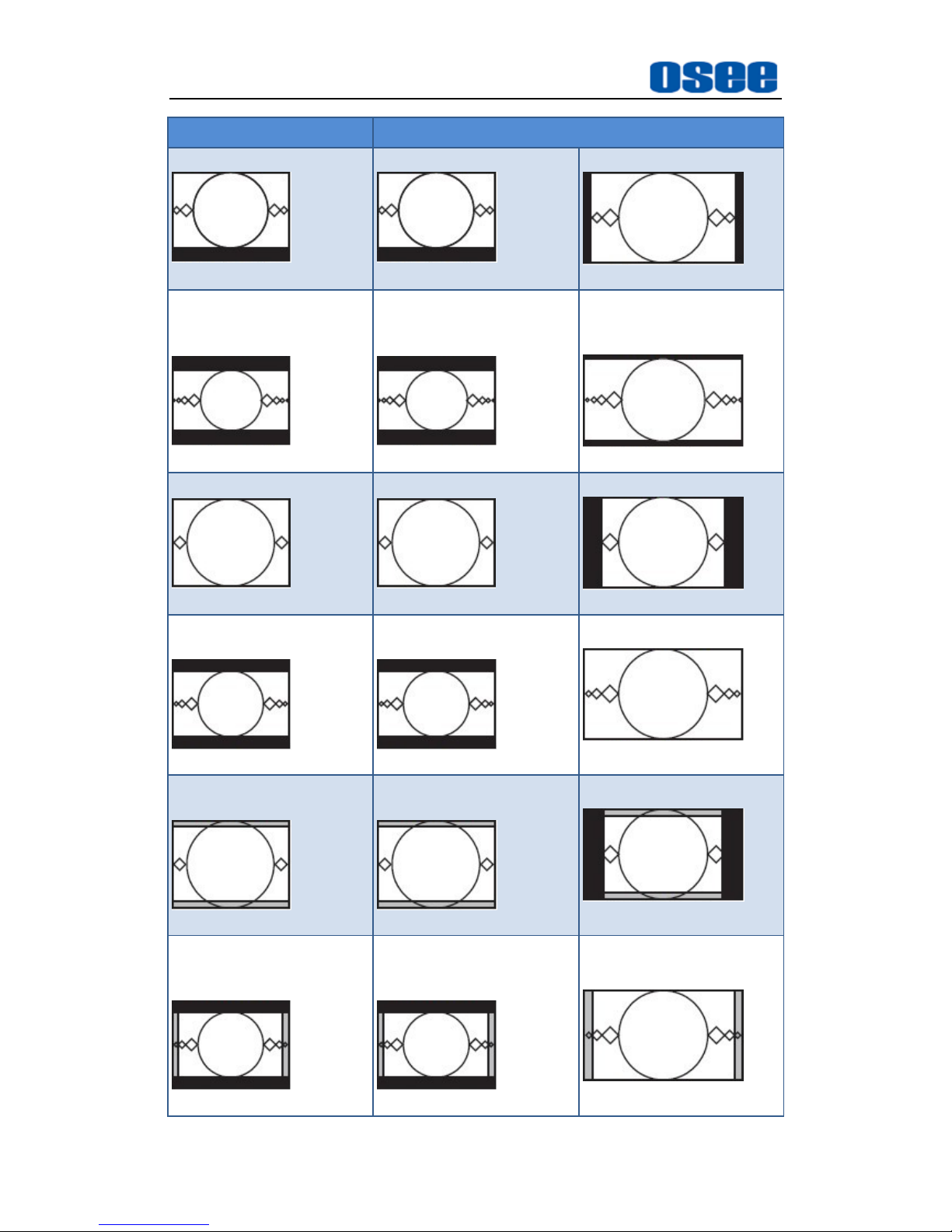
7.3 Converting from 4:3 to 16:9
Input AFD
Output AFD
4:3 Coded Frame
4:3 Coded Frame
16:9 Coded Frame
16:9 LetterBox at the top
in a 4:3 Coded Frame
AFD Code:0010
16:9 LetterBox at the top
in a 4:3 Coded Frame
AFD Code:0010
16:9 Coded Full Frame
AFD Code:1000
14:9 LetterBox at the top
14:9 LetterBox at the top
14:9 Centered image in a
Page 40
Appendix
34
Input AFD
Output AFD
in a 4:3 Coded Frame
AFD Code:0011
in a 4:3 Coded Frame
AFD Code:0011
16:9 Coded Frame
AFD Code:1011
Aspect ratio greater than
16:9 LetterBox in a 4:3
Coded Frame
AFD Code:0100
Aspect ratio greater than
16:9 LetterBox in a 4:3
Coded Frame
AFD Code:0100
16:9 LetterBox with
aspect ratio greater than
16:9
AFD Code:0100
4:3 Full Frame
AFD Code:1000
4:3 Full Frame
AFD Code:1000
4:3 pillarbox
AFD Code:1001
16:9 LetterBox in 4:3
Coded Frame
AFD Code:1010
16:9 LetterBox in 4:3
Coded Frame
AFD Code:1010
16:9 Coded Full Frame
AFD Code:1000
4:3 Centered at 14:9,4:3
Coded Frame
AFD Code:1101
4:3 Centered at 14:9,4:3
Coded Frame
AFD Code:1101
4:3 with 14:9 Center
AFD Code:1101
16:9LetterBox,14:9
Alternative Centered, in
4:3 Coded Frame
AFD Code:1110
16:9LetterBox,14:9
Alternative Centered, in
4:3 Coded Frame
AFD Code:1110
16:9 with 14:9 Center
AFD Code:1110
Page 41
Appendix
35
Input AFD
Output AFD
16:9 LetterBox,4:3
Alternative Centered, in
4:3 Coded Frame
AFD Code:1111
16:9 LetterBox,4:3
Alternative Centered, in
4:3 Coded Frame
AFD Code:1111
16:9 with 4:3 Center
AFD Code:1111
14:9 LetterBox,
Centered, in 4:3 Coded
Frame
AFD Code:1011
14:9 LetterBox,
Centered, in 4:3 Coded
Frame
AFD Code:1011
14:9 Centered image in a
16:9 Coded Frame
AFD Code:1011
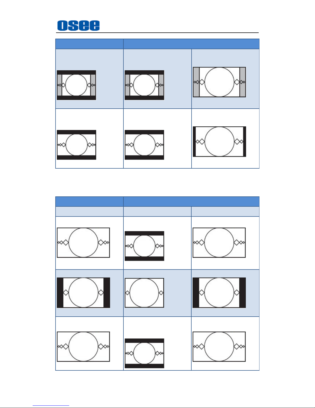
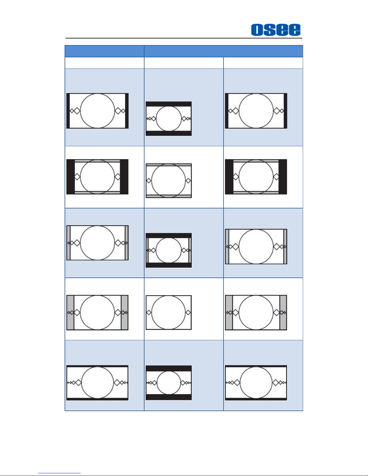
7.4 Converting from 16:9 to 4:3
Input AFD
Output AFD
16:9 Coded Frame
4:3 Coded Frame
16:9 Coded Frame
16:9 Coded Full Frame
AFD Code:1000
16:9 LetterBox in 4:3
Coded Frame
AFD Code:1010
16:9 Coded Full Frame
AFD Code:1000
4:3 pillarbox
AFD Code:1001
4:3 Full Frame
AFD Code:1000
4:3 pillarbox
AFD Code:1001
16:9 Coded Full Frame
with Protected Area
AFD Code:1010
16:9 LetterBox in 4:3
Coded Frame
16:9 Coded Full Frame
with Protected Area
AFD Code:1010
Page 42
Appendix
36
Input AFD
Output AFD
AFD Code:1010
14:9 Centered image in a
16:9 Coded Frame
AFD Code:1011
14:9 LetterBox,
Centered, in 4:3 Coded
Frame
AFD Code:1011
14:9 Centered image in a
16:9 Coded Frame
AFD Code:1011
4:3 with 14:9 Center
AFD Code:1101
4:3 Centered at 14:9,4:3
Coded Frame
AFD Code:1101
4:3 with 14:9 Center
AFD Code:1101
16:9 with 14:9 Center
AFD Code:1110
16:9LetterBox,14:9
Alternative Centered, in
4:3 Coded Frame
AFD Code:1110
16:9 with 14:9 Center
AFD Code:1110
16:9 with 4:3 Center
AFD Code:1111
4:3 Full Frame
AFD Code:1000
16:9 with 4:3 Center
AFD Code:1111
16:9 LetterBox with
aspect ratio greater than
16:9
AFD Code:0100
Aspect ratio greater than
16:9 LetterBox in a 4:3
Coded Frame
AFD Code:0100
16:9 LetterBox with
aspect ratio greater than
16:9
AFD Code:0100
------------------No Text Below------------------
Page 43

FOR MORE INFORMATION PLEASE VISIT: http://www.osee-dig.com/
OSEE TECHNOLOGY CO., LTD.
No.22 Building, No.68 zone, Beiqing Road, Haidian District, Beijing, China
Tel: (+86) 010-62434168, Fax: (+86) 010-62434169
E-mail: [email protected]
 Loading...