

OSEE DEC6800N, DES6800N User Manual

DEC/DES6800 CVBS/SDI Converter
USER MANUAL

Product Information
Model:
DEC/DES6800 CVBS/SDI Converter
Version:
V010000
Release Date:
March 28th, 2008
Company
OSEE TECHNOLOGY CO., LTD.
Contact Information
Address:
No.22 Building, No.68 zone, Beiqing Road, Haidian District,
Beijing, China
Post Code:
100094
Tel:
(+86) 010-62434168
Fax:
(+86) 010-62434169
Web:
http://www.osee-dig.com/
E-mail:
sales@osee-dig.com

Contents
Chapter 1 Introduction .......................................................................................... 1
Overview ............................................................................................................................................ 1
General Description of Modules ........................................................................................................ 1
Features .............................................................................................................................................. 1
Introduction to Module ...................................................................................................................... 2
The Front Part of Module ........................................................................................................... 2
Back Connector .......................................................................................................................... 4
Back Connector for DEC/DES6800N ........................................................................................ 4
Signal Flow Chart .............................................................................................................................. 5
Chapter 2 Installation ........................................................................................... 5
Overview ............................................................................................................................................ 5
Maximum Power Dissipation for Frame ............................................................................................ 6
Unpacking the Module ....................................................................................................................... 6
Preparation for Installation ......................................................................................................... 6
Check Packing List .................................................................................................................... 6
Module Installation ............................................................................................................................ 6
Signal Connections .................................................................................................................... 7
Module Removal ........................................................................................................................ 7
Chapter 3 Operation and Control ......................................................................... 8
User Control and Operating Instruction ............................................................................................. 8
Pay attention to the followings when configuration ......................................................................... 14
Composite in Video Path Processing: ...................................................................................... 14
Decoded Video Path Processing: .............................................................................................. 15
Video Timing and Freeze Controls .......................................................................................... 15
Freeze Mode ............................................................................................................................. 15
OSD Mode ............................................................................................................................... 15
Set the Jumper .................................................................................................................................. 15
Chapter 4 Specifications ..................................................................................... 16
Analog Video Input .......................................................................................................................... 16
SDI Video Processing ...................................................................................................................... 16
SDI Video Output ............................................................................................................................. 16
Phase ................................................................................................................................................ 16
Chapter 5 Warranty for osee product ................................................................ 17
What the warranty covers: ............................................................................................................... 17
What the warranty does not cover: ................................................................................................... 17

DEC/DES6800 CVBS/SDI Converter - 1 -
DEC/DES6800 CVBS/SDI Converter
Chapter 1 Introduction
Overview
In this chapter the following modules are introduced:
DEC6800N:Supporting one composite loop output, two SDI output and two SDI outputs with OSD.
DES6800N:Supporting one composite loop output, one REF loop input, one REF loop output, two SDI
output and two SDI outputs with OSD.
The above modules can be installed in the 6800N Series frame.
General Description of Modules
The DEC/DES6800N is a compact 12-bit decoder and can convert NTSC, PAL and composite signal
into 4:2:2 SDI component signal with broadcasting quality.
The module can handle the signal like the satellite feed and microwave which contains a plenty of noise.
The DES6800 has a built-in synchronizer.
The DEC/DES6800N is controlled by switch on the front panel. The table1-1 gives a general description
of modules.
Table 1-1 DEC/DES6800N
Module Description
DEC6800N Has one composite loop output, two SDI outputs, and two SDI
outputs with OSD
DES6800N Has one composite loop output, one REF loop input, one REF loop
output, two SDI outputs and two SDI outputs with OSD.
Features
The DEC/DES6800 has the following features:
4 oversampling 12-bit A/D converter
Auto-detection on NTSC/PAL for input
AGC/ACC
Full functional processing amplifier
Progressive VBI processing
Built-in test pattern generator (color bar and black burst)
EDH insertion
OSD can be overlaid to the output
NTSC/PAL reference input
Built-in synchronizer
DEC/DES6800 CVBS/SDI Converter - 2 -
FCC Caution:
Any Changes or modifications not expressly approved by the party responsible for compliance could
void the user's authority to operate the equipment.
This device complies with part 15 of the FCC Rules.
Operation is subject to the following two conditions: (1) This device may not cause harmful interference,
and (2) this device must accept any interference received, including interference that may cause
undesired operation.
Note: This equipment has been tested and found to comply with the limits for a Class B digital device,
pursuant to part 15 of the FCC Rules. These limits are designed to provide reasonable protection against
harmful interference in a residential installation. This equipment generates uses and can radiate radio
frequency energy and, if not installed and used in accordance with the instructions, may cause harmful
interference to radio communications. However, there is no guarantee that interference will not occur in
a particular installation. If this equipment does cause harmful interference to radio or television
reception, which can be determined by turning the equipment off and on, the user is encouraged to try to
correct the interference by one or more of the following measures:
Reorient or relocate the receiving antenna.
Increase the separation between the equipment and receiver.
Connect the equipment into an outlet on a circuit different from that to which the receiver is connected.
Consult the dealer or an experienced radio/TV technician for help.
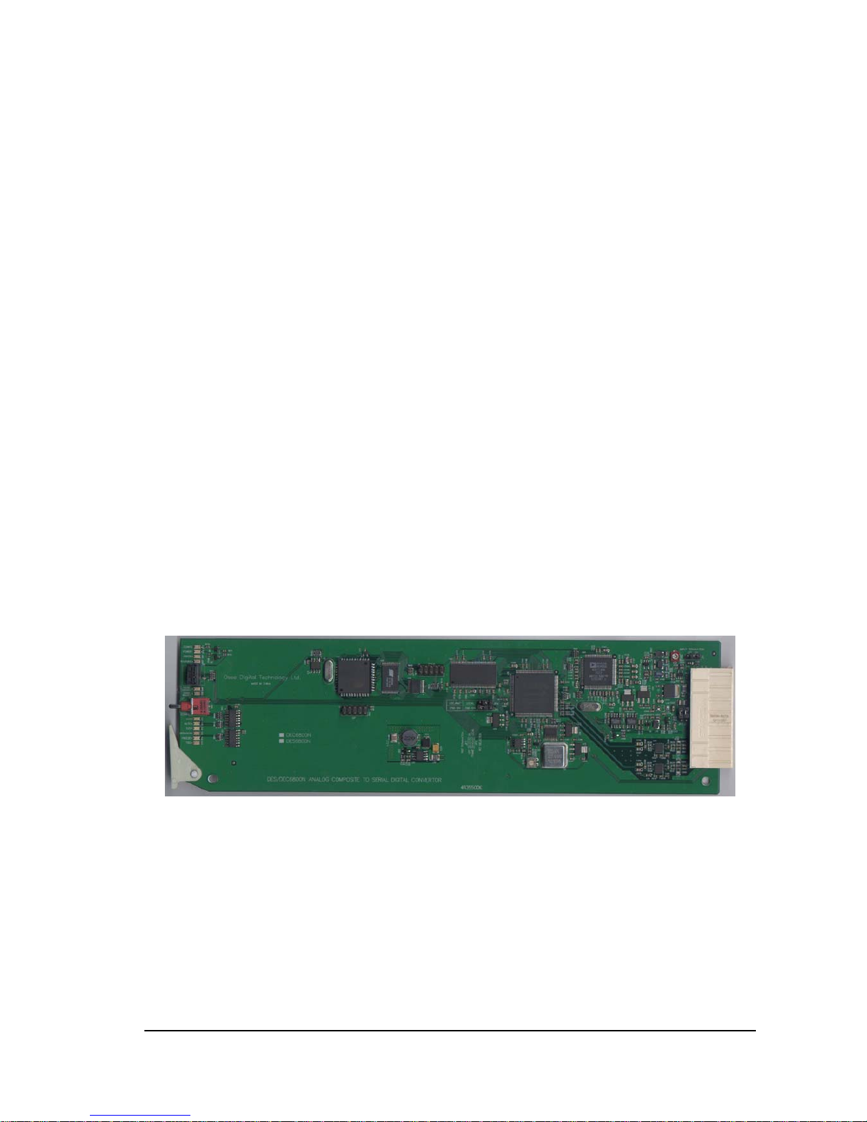
Introduction to Module
The Front Part of Module
Figure 1-1 DEC/DES6800N
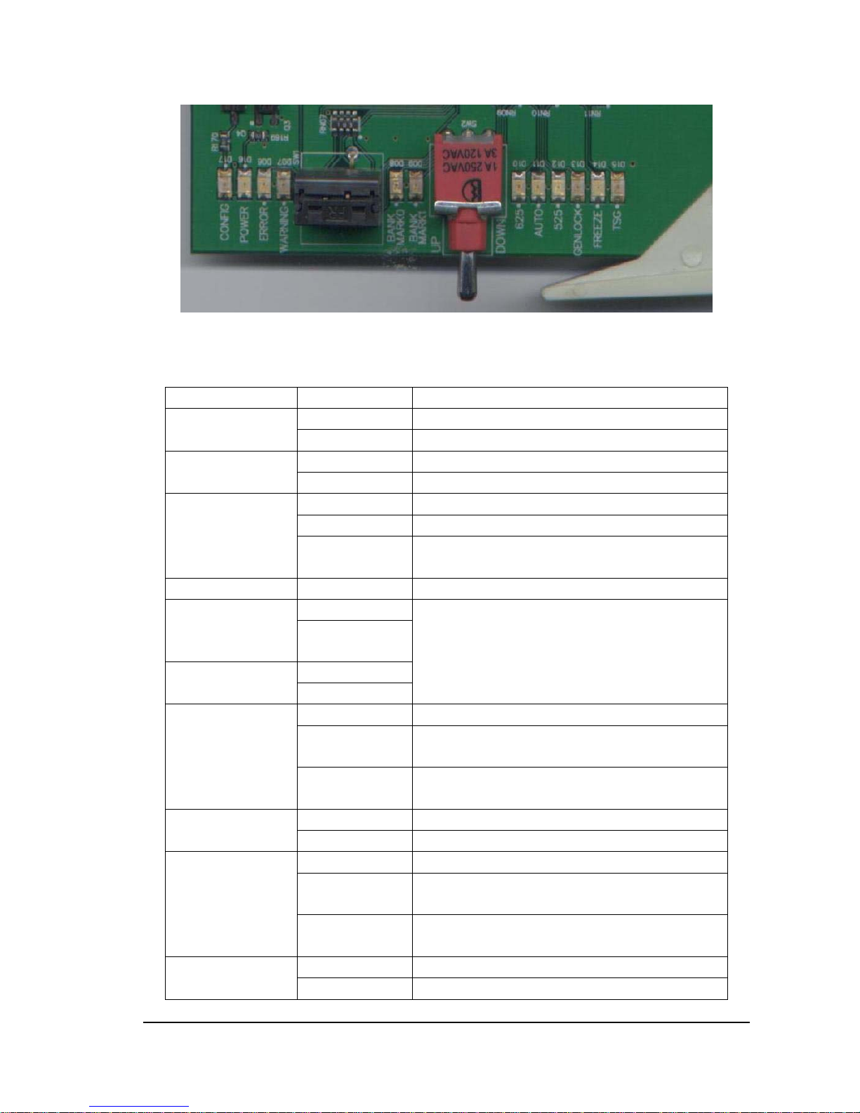
Note: Table 1-1 Introduction to the switch and status LED indicator. Refer to Chapter Three for detailed
instructions on switch and status LED indicator.
DEC/DES6800 CVBS/SDI Converter - 3 -
Figure 1-2 Switch and Status LED Indicator on the Front Part of DEC/DES6800
Table 1-2:Status Indicator and Its Function
LED Indication Condition
CONFIG
(yellow)
Off Module is in normal operating mode.
On Module is initializing or initialized error.
POWER
(green)
Off No power to module
On Normal operation, module is powered.
ERROR
(red)
Off Normal operation.
On continuously No signal present on input.
Flashing No reference or input signal line rate does not match
the reference.
WARNING(red) Off when module runs in disorder
BANK MARK
(yellow)
Bank 0
Off On/Off combination indicates which bank is selected
(described in Table 3)
On
BANK MARK1
(yellow) Bank1
Off
On
625(green)
On continuously Valid 625 video input is present.
Off Standard 625 is not selected or under auto-detection,
no valid 625 standard is detected.
Flashing
Standard 625 is detected and no valid 625 video input
is present.
AUTO(green)
On Auto standard is selected
Off Auto standard is not selected
525(green)
On continuously Valid 525 video input is present.
Off Standard 525 is not selected or under auto-detection,
no valid 525 standard is detected.
Flashing
Standard 525 is selected and no valid 525 video input
is present.
GENLOCK(yellow) Off Reference genlock mode is not selected
On Reference genlock mode is selected
 Loading...