

OSEE BCM-170-3HSV, BCM-156-HSV, BCM-215-HSV, BCM-170-HSV, BCM-230-HSV User Manual
...
BCM Series
LCD Monitor
User Manual


3
Product Information
Model:
BCM-156/170/215/230 Series LCD Monitor
Version:
V010200
Release Date:
July 14th, 2016
Company
OSEE TECHNOLOGY CO., LTD.
Contact Information
Address:
No.22 Building, No.68 zone, Beiqing Road, Haidian District,
Beijing, China
Post Code:
100094
Tel:
(+86) 010-62434168
Fax:
(+86) 010-62434169
Web:
http://www.osee-dig.com/
E-mail:
sales@osee-dig.com

About this manual
Important
The following symbols are used in this manual:
The further information or know-how for described subjects above which
helps user to understand them better.
The safety matters or operations that user must pay attention to when
using this product.
Contents
The user manual applies to the following device types:
BCM-156-3HSV BCM-170-3HSV BCM-215-3HSV BCM-230-3HSV
BCM-156-HSV BCM-170-HSV BCM-215-HSV BCM-230-HSV
BCM-156-SV BCM-170-SV BCM-215-SV BCM-230-SV
BCM-156-V BCM-170-V BCM-215-V BCM-230-V
The above listed devices have most similarities on appearance and
characteristics. The images of BCM-156-3HSV are adopted in the following
descriptions.
Any of the different specifications between the device types are elaborated.
Before reading the manual, please confirm the device type.

I
Contents
Contents .......................................................................................................... I
Chapter 1 Overview ....................................................................................... 1
Chapter 2 Safety ............................................................................................. 3
Chapter 3 Unpack and Installati on ............................................................... 7
Chapter 4 BCM Features ............................................................................... 9
4.1
Front Panel Features ........................................................................ 1 1
4.1.1 Arrangement of Front Panel ........................................................... 11
4.1.2 Operation of Front Panel ................................................................ 12
4.2
Rear Panel Features .......................................................................... 16
4.2.1 Arrangement of Rear Panel ............................................................ 17
4.2.2 Operations of Rear Panel ............................................................... 19
4.3
Supported Signal Format ................................................................. 22
Chapter 5 Functionality of the Main Menu ................................................. 25
5.1
Main Menu ......................................................................................... 25
5.1.1 STATUS Menu ............................................................................... 27
5.1.2 INPUT SELECT Menu .................................................................... 29
5.1.3 MARKER Menu .............................................................................. 32
5.1.4 AUDIO Menu .................................................................................. 35
5.1.5 DISPLAY Menu .............................................................................. 39
5.1.6 CLOSED CAPTION Menu .............................................................. 41
5.1.7 CONFIG Menu ................................................................................ 43
5.1.8 COLOR TEMP Menu ...................................................................... 50
5.1.9 FUNCTION KEY Menu ................................................................... 52
5.1.10 GPI Menu ...................................................................................... 54
5.1.11 IMD Menu ..................................................................................... 57
5.1.12 KEY INHIBIT Menu ....................................................................... 73
5.2
Menu Settings .................................................................................... 74
Chapter 6 Network Control .......................................................................... 79
6.1
Access the settings ........................................................................... 79
6.2
Menu Control ..................................................................................... 80

6.2.1 ADJUST Menu ................................................................................ 81
6.2.2 VIDEO DISPLAY Menu .................................................................. 83
6.2.3 SYSTEM Menu ............................................................................... 83
6.2.4 Other Menus ................................................................................... 84
6.3
Parameter Settings ........................................................................... 85
Chapter 7 Specifications ............................................................................. 89

Overview
1
Chapter 1 Overview
The BCM series LCD Monitor are high performance broadcast monitor tailoring
most applications from program production, intensive upload/download,
playout to studio and intensive monitoring all sorts of business in TV Stations.
The front frame of the unit comes in a slim bezel design made from rubber
mold. The professional IPS glass at full resolution of 1920 x 1080 with LED
backlight makes the BCM series LCD monitor capable of reproducing a natural
color at quickest response time. In addition, the unit boasts a full wide viewing
angle as well as excellent brightness and contrast ratio.
By adopting the advanced 10-bit digital signal processing technology plus 3D
comb filter, de-interlacing capability and accurate scaling ensures the BCM
series LCD Monitor to achieve a better effect of smoother and more natural
image.
The BCM series LCD Monitor supports up to 2Ch 3G/HD/SD-SDI/analog
input/output, 2Ch CVBS(LINE1, LINE2) input/output, IGRP Y/C input/output,
IGRP YPbPr input/output, and 1Ch HDMI input. Featuring PBP/PIP and
showing two signals simultaneously on the same screen makes the BCM with
added value.
The BCM series LCD Monitor delivers much capable display functionality like
waveform/vector scope, audio de-embedding, audio monitoring, audio
metering bar, TC, CC, AFD, IMD and all kinds of markers.
Figure 1 A Diagram of BCM Monitor
Features
Prevailing slim bezel design
Having multi format input including 3G-SDI
Adopting full HD, wide viewing angle IPS glass

Overview
2
Using 10-bit signal processing technology plus advanced conversion
technology between the interlacing and the progressive
Featuring PBP and PIP, dual 3G-SDI capable under PBP mode
Supporting waveform/vector scope, audio metering bar, TC, IMD and
CC
Supporting varied color temperature, varied scan modes, flexibility in
marker setting, Blue Only/Monochrome mode
Functionality
Supports MARKER, Time Code, MET display
Supports presetting the color temperature using customized values

Safety
3
Chapter 2 Safety
FCC Caution
:
Any Changes or modifications not expressly approved by the party responsible
for compliance could void the user's authority to operate the equipment.
This device complies with part 15 of the FCC Rules.
Operation is subject to the following two conditions: (1) This device may not
cause harmful interference, and (2) this device must accept any interference
received, including interference that may cause undesired operation.
Note: This equipment has been tested and found to comply with the limits for a
Class B digital device, pursuant to part 15 of the FCC Rules. These limits are
designed to provide reasonable protection against harmful interference in a
residential installation. This equipment generates uses and can radiate radio
frequency energy and, if not installed and used in accordance with the
instructions, may cause harmful interference to radio communications.
However, there is no guarantee that interference will not occur in a particular
installation. If this equipment does cause harmful interference to radio or
television reception, which can be determined by turning the equipment off and
on, the user is encouraged to try to correct the interference by one or more of
the following measures:
Reorient or relocate the receiving antenna.
Increase the separation between the equipment and receiver.
Connect the equipment into an outlet on a circuit different from that to which
the receiver is connected.
Consult the dealer or an experienced radio/TV technician for help.

Safety
4
Warnings:
Read, keep and follow all of these instructions for your safety. Heed all
warnings.
Device
Install in accordance with the manufacturer's instructions.
Do not beat with a hard object or scratch the LCD display.
Do not make the freeze picture displaying on the screen time too long,
otherwise, it will leave the afterimage on the screen.
If the brightness is adjusted to the minimum, then it might be hard to
see the display screen.
Refer all servicing to qualified service personnel. Servicing will be
required under all of the following conditions:
The unit has been exposed to rain or moisture.
Liquid had been spilled or objects have fallen onto the unit.
The unit has been damaged in any way, such as when the
power-supply cord or plug is damaged.
The unit does not operate normally.
Clean only with dry cloth.
Specifications are subject to change without notice.
Position
Do not block any ventilation openings.
Do not use this unit near water.
Do not expose the unit to rain or moisture.
Do not use this unit near any heat sources such as radiators, heat
registers, stoves, or other apparatus (including amplifiers) that product

Safety
5
heat.
A nameplate indicating operating voltage, etc., is located on the rear
panel.
The socket-outlet shall be installed near the equipment and shall be
easily accessible.
Power Supply Cord
Do not defeat the safety purpose of the polarized or grounding-type
plug.
Do not damage the power cord, place the heavy objects on the power
cord, stretch the power cord, or bend the power cord.
Protect the power cord from being walked on or pinched, particularly at
plugs, convenience receptacles, and the point where they exit from the
unit.
If the power cord is damaged, turn off the power immediately. It is
dangerous to use the unit with a damaged power cord. It may cause
fire or electric shock.
Unplug this unit during lighting storms or when unused for long periods
of time.
Disconnect the power cord from the AC outlet by grasping the plug, not
by pulling the cord.
Should any solid object or liquid fall into the cabinet, unplug the unit
and have it checked by qualified personnel before operating it any
further.

6
Unpack and Installation
7
Chapter 3 Unpack and Installation
Unpack:
When unpacking the components of BCM-156 monitor, please verify that none
of the components listed in Table 3.1 are damaged or lack. If there is any
missing, contact your distributors or Osee Technology Co., Ltd. for it.
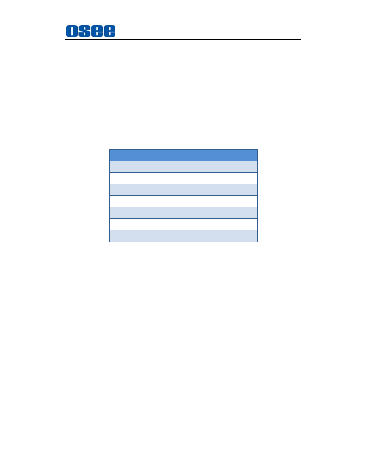
Table 3-1 Packing List
No. Item Quantity
1 Device 1
2 Pedestal with screws 1
3 Power cord 1
4 adapter 1
5 User manual 1
6 Warranty card 1
7 Certificate card 1
Installation:
1. Prepare for installation
Please follow the procedures below before installing BCM-156:
Check the equipment for any invisible damage that may have occurred
during transit.
Confirm all the items listed on the packing list have been received.
Remove all the packing material including electrostatic-resistant
packing.
Retain these packing materials for future use.
2. Mount a BCM-156 in your desired location of a standard rack.
Adequate ventilation is required when installed to prevent possible
damage to the BCM-156.
3.
Connect required cables for signal input and output. For BNC
connections use 75Ω rated connectors.
4.
Connect 12V5A DC power source using the included power cord.
5.
Connect the power cord to the power interface.
6.
Fasten the power protect accessory.

Unpack and Installation
8
7.
As a final step, turn on the device by pressing the corresponding
power switch located on the front panel.
The pedestal and the monitor are packaged separately.
Connect a standard signal line to the corresponding input port. All BNC
connector impedance must be 75Ω.
Please use the power adapter supplied to avoid unnecessary trouble.
The factory default value for IP address is 192.168.1.86.

BCM Features
9
Chapter 4 BCM Features
This chapter describes the features of BCM-156 monitor. The features of
BCM-156 monitor are as shown in Figure 4-1 after installed and powered on:
SDI1
1080I59.94
IMD
--:--:--:--
1 2345678
Status Information
Audio Meter
Center Marker
IMD
Timecode
Safe Marker
Area Marker
Adjust Menu
Wave Form
AFD CC
F1 NORMALSCAN
F2 OFFNATIVE
FUNCTION
F3 4:3ASPECT
F4
MAIN
WIN SELECT
F5 OFF
PBP
Figure 4-1 Features of BCM-156 Monitor
1.
Status Information
It is displayed in the top left corner of the screen, and includes the
input channel and signal format. You can define it in DISPLAY menu.
2.
Waveform and Vector
This is effective only for SDI signal. The waveform and vector of the
input signal are configurable in the MAIN Menu.
3.
Area Marker
It is used to mark different area of the image. You can set whether to
display it or not and their displaying mode in MARKER menu.
4.
Safe Marker
It is used to mark different area of the image. You can set whether to
display it or not and their displaying mode in MARKER menu
5.
Center Marker
It is displayed in the center of the screen, and marks the center of the

BCM Features
10
image. You can set whether to display it or not in MARKER menu.
6. Audio Meter
It is displayed for audio monitoring. You can set its groups, direction,
position and mode in AUDIO menu.
7. Timecode
It is displayed at the bottom of the image, the format is HH:MM:SS:FF,
if there is no timecode available, the monitor will display --:--:--:--.
8. IMD
The IMD text displays at the bottom of the screen, the length can’t
exceed 16 characters, and you can choose letter, number or other
character for it.
9.
AFD/CC
AFD and CC information will display at the top center of the screen as
an icon.
10.
MUTE
The icon for MUTE is . When it is mute, this icon displays at the
bottom right position of the screen. You can set this function in function
key.
The
Status Information
usually displays as the following situations:
"UNKNOW” appears if an unsupported signal is input.
“NO SIGNAL” appears if no signal is input.
The signal is normal, for example: 1080i59.94, NTSC, 1280X1024,
etc.
When the monitor is set in PIP or PBP mode by setting the
CONFIGSUB IN TYPE
menu item, the
Status Information
for the main
picture displays at the top left corner of the screen, and the
Status
Information
for the slave picture displays at the top right corner of the
screen.
The AFD information displays at the top center of the screen.
BCM Features
11
4.1 Front Panel Features
It will introduce the arrangement and the operations of the buttons in front of
the panel in the following.
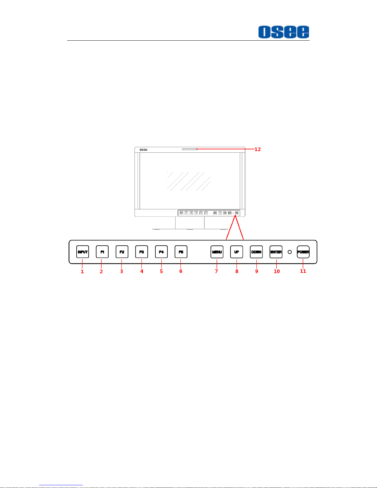
4.1.1 Arrangement of Front Panel
There are a series of buttons at the bottom of the screen, and these
buttons are used to control the screen menu items.
Figure 4.1-1 the Buttons in Front Panel
As shown in Figure 4.1-1, take the left screen of BCM-156 for example,
these buttons are as follows:
1.
INPUT
2.
F1
3.
F2
4.
F3
5.
F4
6. F5
7.
MENU
8.
UP
9. DOWN
10.
ENTER
BCM Features
12
11.
POWER
12. TALLY: TALLY indicator(LED TALLY)
Only the POWER button has a light indicator.
4.1.2 Operation of Front Panel
The functionality and usage of the buttons at the front panel are as
follows:
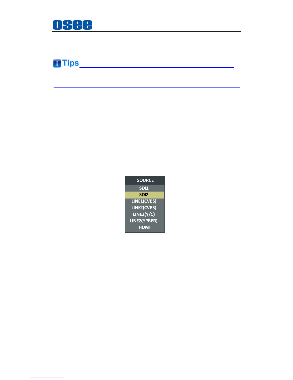
1.
INPUT
Select the input signal. Press this button to display the input source
menu at the right top corner of the screen, as shown in Figure 4.1-2. Use
it to select an input signal source, press it again to toggle among these
input signal items, or after the input source menu displayed, use the
UP/DOWN button to toggle among these input signal items.
Figure 4.1-2 Source Menu
The one-to-one correspondence between the signals in the source menu
list and the interfaces in the back panel are shown in Figure 4.1-3:
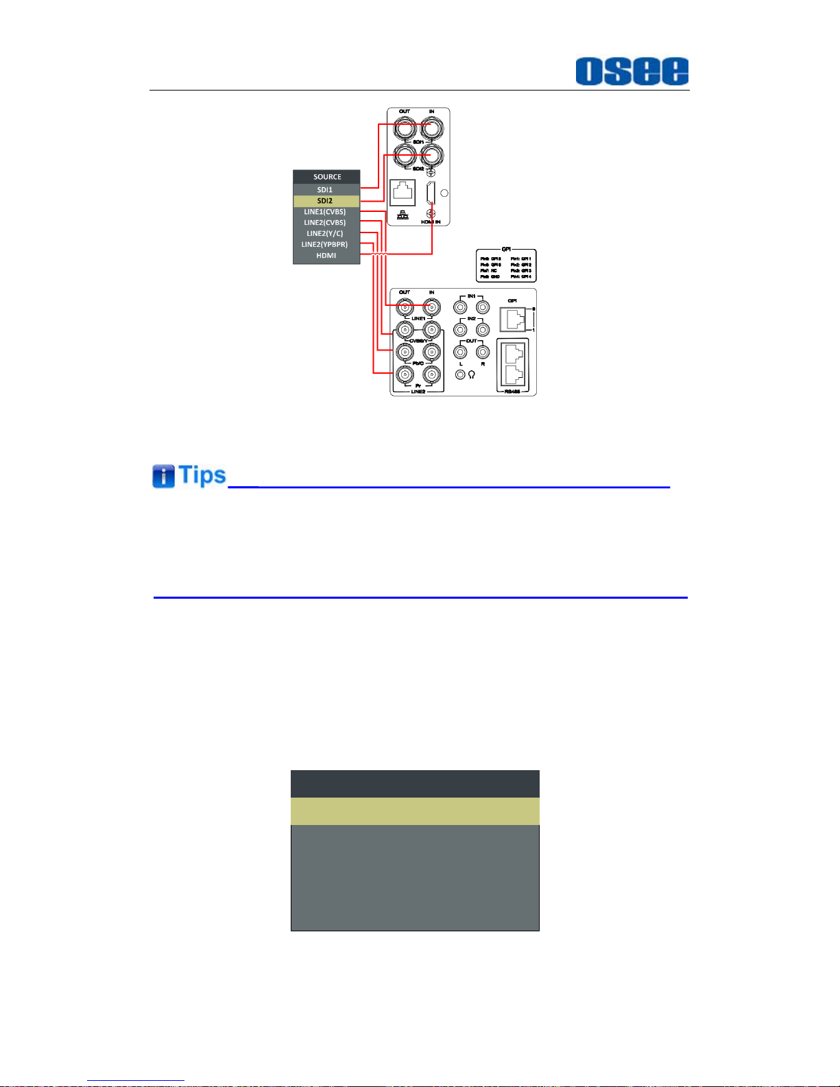
BCM Features
13
Figure 4.1-3 Correspondence between Source Menu and Interface
When the monitor is set as PIP/PBP display mode, set the signal source
for the main picture by INPUT button, and refer to “5.1.7 CONFIG Menu”
for the settings about the signal source for the slave picture.
2.
F1
This button is a FUNCTION button. The function can be set via the
FUNCTION menu. Open the FUNCTION menu after the first time, the
selected function will remain.
OPERATION:
Press F1 to display the function menu list in the center
of the screen, as shown in Figure 4.1-4. Toggle F1 button to change
the value related to this function.
F1 NORMALSCAN
F2 OFFNATIVE
FUNCTION
F3 4:3ASPECT
F4 MAINWIN SELECT
F5 OFFPBP
Figure 4.1-4 Function Menu List
BCM Features
14
After you have loaded the function menu list, it will be closed automatically
if you do nothing operation with it in 10s.
If the value related to the function button can’t be modified, the value
shows in blue.
Use
FUNCTION KEY
menu to assign F1~F5. You can assign the function
from among: SCAN, NATIVE, ASPECT, BLUE ONLY, MONO, MARKER,
H/V DELAY, AUDIO METER, FAST MODE, TC, IMD, MUTE, PBP, CC,
FREEZE, WIN SELECT, FOCUS ASSIST, LUMA ZOOM CHECK, H FLIP,
UNDEF. Refer to "5.1.9 FUNCTION KEY Menu" for the details.
3.
F2
It is used to activate to F2 function button. The operation is as the same
as F1's.
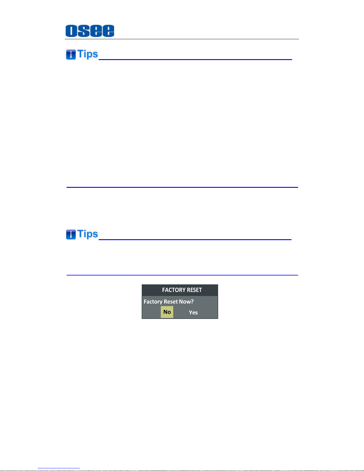
Press and hold the
INPUT+F2
button for 3s can reset the menu settings
to factory originals, as shown in Figure 4.1-5.
Figure 4.1-5 Reset Menu List
4.
F3
It is used to activate to F3 function button. The operation is as the same
as F1's.
5.
F4
It is used to activate to F4 function button. The operation is as the same
as F1's.
6.
F5
It is used to activate to F5 function button. The operation is as the same

BCM Features
15
as F1's.
7.
MENU
It is used to activate the Main menu. Press this button to do some
operations with the Main menu, it includes the following operations:
Display the Main menu
Back to the higher level menu
Quit the Main menu
Refer to “5.2 Menu Settings” for detail about the main menu operations.
8.
UP
It is UP button when working with
MENU
. Toggle this button to select the
next item or increase the number.
9.
DOWN
It is
DOWN
button when working with
MENU
. Toggle this button to select
the next item or decrease the number.
10.
ENTER
This button can achieve the following two situations:
Work with the Main MENU
: when working with the Main menu,
ENTER button achieve the following functions:
Enter into the next level menu: press
ENTER
button, you will enter
into the menu item as this relationship: the Main menu list
sub-menu list sub-menu value list, the current editable object is
in yellow control icon;
Confirm the value selection: press
ENTER
button to confirm the
value selection.
Adjust Menu:
when not displaying the Main menu, press
ENTER
button to display the adjust menu list, as shown in Figure 4.1-6,
toggle among these menu items: VOLUME, BRIGHTNESS,
CONTRAST, CHROMA.
BRIGHTNESS 50
Figure 4.1-6 Adjust Menu List
After displaying the Adjust menu, press UP or
DOWN
button to adjust
the menu value, and then press
ENTER
button to confirm the value
selection.
The relationship of the menu items and their range is shown in Table
4.1-1:

BCM Features
16
Table 4.1-1 The Description of Adjust Menu Items
Adjust Menu Description Range Default
VOLUME Adjust the volume 0~31dB 16
BRIGHTNESS Adjust the image brightness 0~100 50
CONTRAST Adjust the image contrast 0~100 50
CHROMA Adjust the image monochroma 0~100 50
Set these parameter values in the following position: BRIGHTNESS,
CONTRAST, CHROMA.
In Adjust Menu List on screen when pressing Enter key.
In Adjust menu of network control page.
After you have loaded the adjust menu list, it will be closed automatically if
you do nothing operation with it in 10s.
The main menu, the adjust menu, the function menu and the input signal
selection list of a screen may not be shown all simultaneously.
11.
Power
Used to power on or standby, and the light in the button will indicate the
status of the power. If the light is green, the monitor is powered on, if the
light is flashing, the monitor is standby.
When the device is standby, cut off the power and restart the device, the
status of the device will be normal but not standby.
4.2 Rear Panel Features
It will introduce the arrangement and the operations of the interfaces in rear
of the panel in the following.
BCM Features
17
4.2.1 Arrangement of Rear Panel
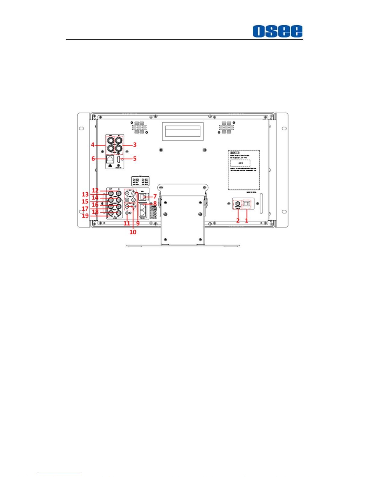
For the arrangement of the rear panel of BCM-170, BCM-215 and
BCM-230 are the same, which are different from the BCM-156’s. It will
take BCM-170 for example, as shown in Figure 4.2-1, there are various
input and output interfaces at the rear panel of BCM-170 monitor.
Figure 4.2-1 The Rear Panel of BCM-170 Monitor
The interfaces numbered from 1 to 8 in red dotted rectangle are
described as follows:
1.
Power Switch
2. Power Input
3.
Video Input: SDI1 IN, SDI2 IN
4.
Video Output: SDI1 OUT, SDI2 OUT
5.
HDMI Input
6.
Ethernet
7.
GPI interface
8.
RS485 In/Out
9. Audio Input
10.
Audio Output
11.
Headphone Output Connector (3.5mm stereo Jack)
BCM Features
18
12.
Video Input: LINE1 IN
13. Video Output: LINE1 OUT
14.
Video Input: LINE2(CVBS/Y) IN, feed the composited LINE2, or
component Y signal.
15. Video Output: LINE2(CVBS/Y) OUT, output the composited LINE2,
or component Y signal.
16.
Video Input: LINE2(Pb/C) IN, feed the component Pb, or
component C signal.
17.
Video Output: LINE2(Pb/C) OUT, output the component Pb, or
component C signal.
18.
Video Input: LINE2(Pr) IN, feed the component Pr signal.
19.
Video Output: LINE2(Pr) OUT, output the component Pr signal.
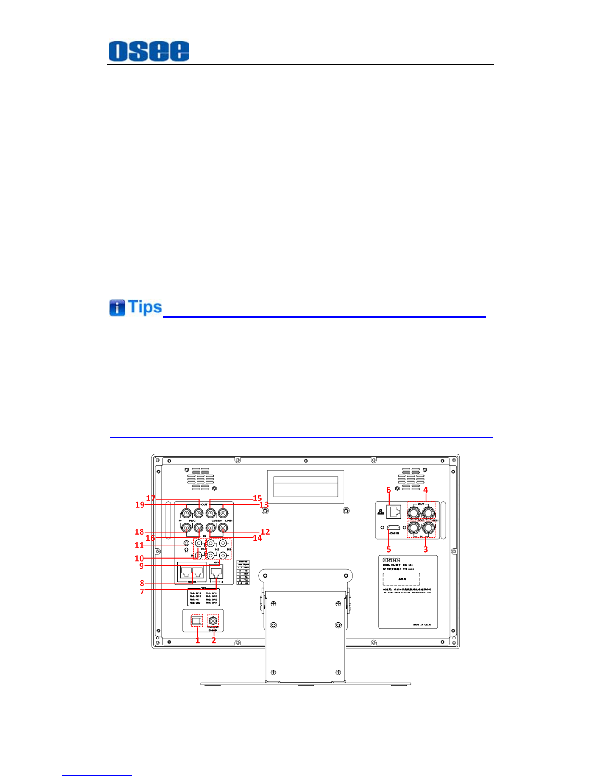
Especially, the interface types of BCM-156 are as the same as BCM-170’s
(BCM-215/BCM-230), but the arrangement is different from the
BCM-170’s (BCM-215/BCM-230). The arrangement of rear panel of
BCM-156 is as shown in Figure 4.2-2, the numbers of the interfaces are
the same.
Figure 4.2-2 The Rear Panel of BCM-156 Monitor
BCM Features
19
4.2.2 Operations of Rear Panel
The details of these interfaces at the rear panel are described as follows:
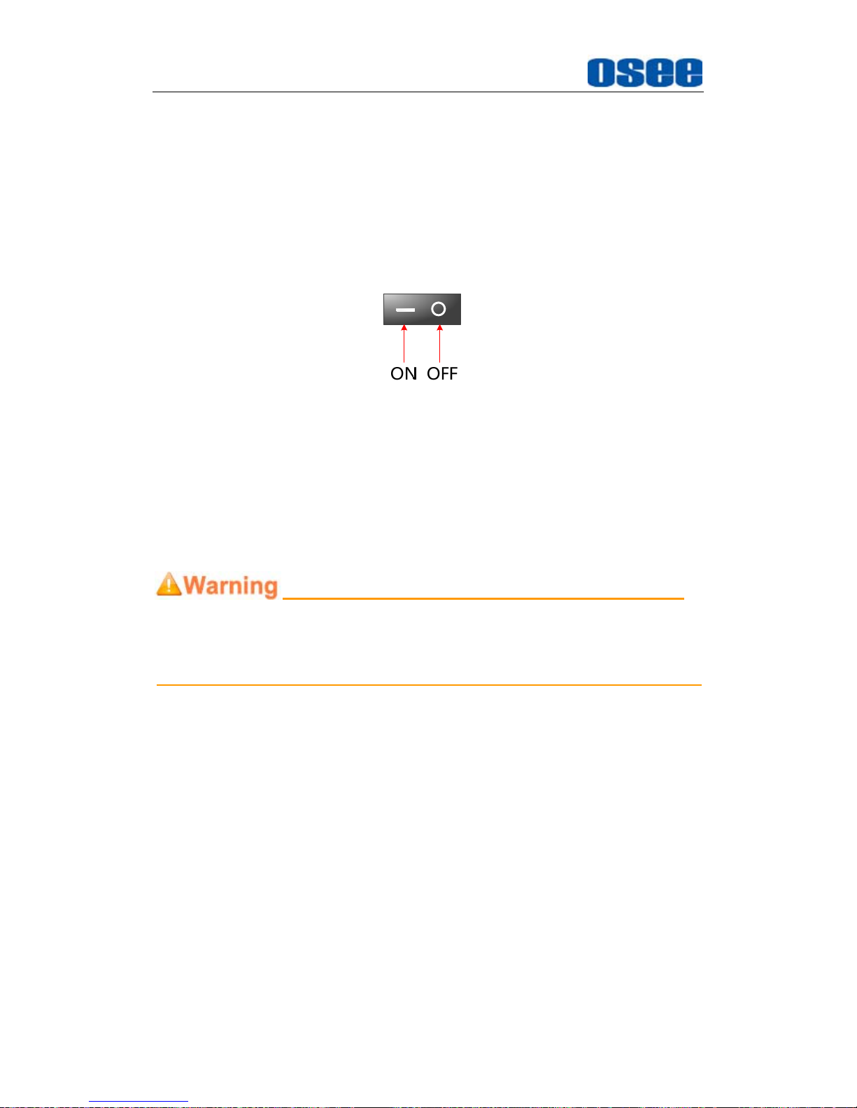
1. Power Switch
It provides one power switch to switch on or switch off. As shown in
Figure 4.2-3, push the button to the direction “-” to switch on the power,
or push the button to the direction “” to switch off the power.
Figure 4.2-3 Power Switch
2.
Power Input
It provides one power input interface, the specification is 12V5ADC.
The corresponding indicator is at the front panel. If the light is green,
the monitor is powered on, if the light is flashing, the monitor is standby,
and if the light is off, the monitor is powered off.
Only use the adapter and the power cord specified by the manufacture for
your safety!
3.
Video Input Interface (BNC)
It provides two SDI input interfaces, one is labeled as SDI1 IN, and the
other is SDI2 IN.
4.
Video Output Interface (BNC)
It provides two SDI output interfaces. One is labeled as SDI1 OUT, the
other is SDI2 OUT, active loop.
5.
HDMI
It provides one HDMI input interface, HDMI Type-A connector with a
fastener.
6.
Ethernet (RJ-45)
It provides one 10/100M Ethernet connector. It is used to connect with
a computer to modify the network settings.
BCM Features
20
7.
GPI(DB9)
It assigns a function to each pin of the GPI interface to realize a
remote control mode. Define a function to the GPI pin. Refer to “5.1.10
GPI Menu” for the definition of the pins and the functions.
The relationship of the pins of GPI interface and its channel value is
shown in Table 4.2-1.
Table 4.2-1 The Relationship of GPI Pins and Channel Values
Pin No. Channel Value
Pin 1 GPI1
Pin 2 GPI2
Pin 3 GPI3
Pin 4 GPI4
Pin 5 GPI5
Pin 6 GPI6
Pin 7 NC
Pin 8 GND
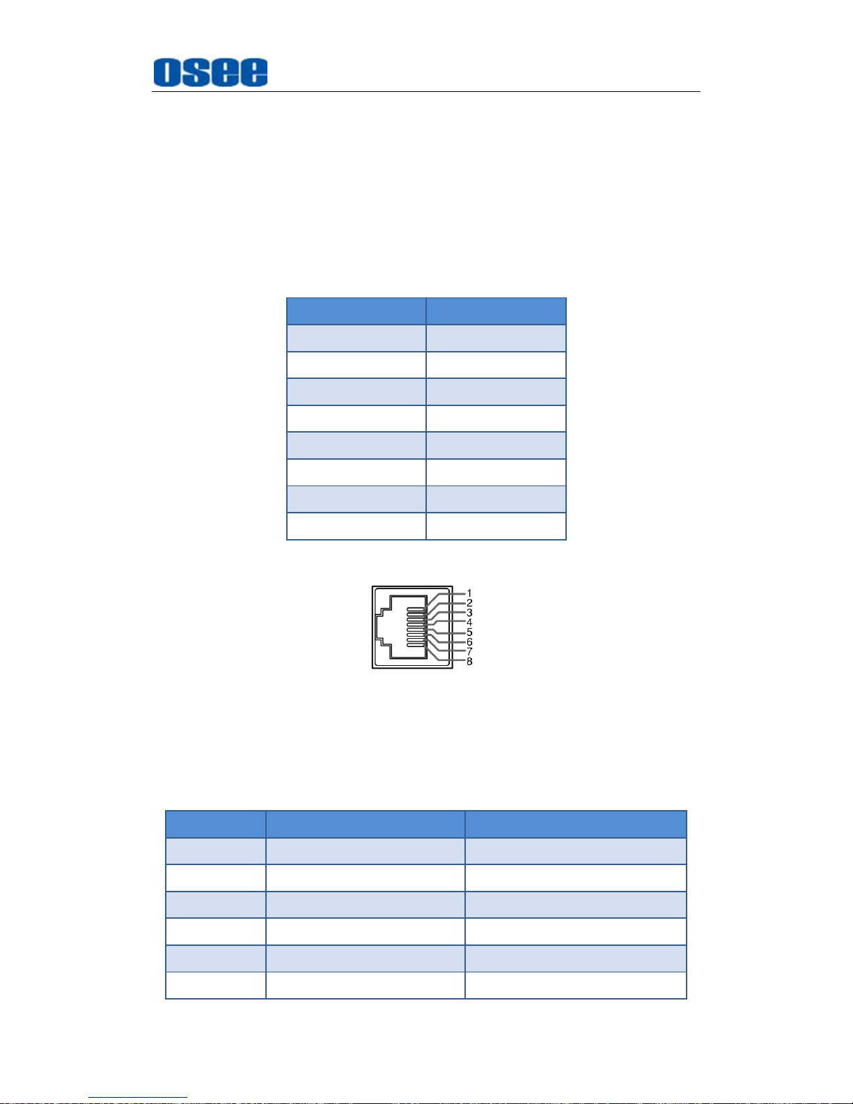
8.
IN/ OUT RS485 Interface (RJ-45)
Support for dynamic IMD and updating the new firmware.
The Comparison of Pins and Input/output connectors for RS485 is
shown as in Table 4.2-2:
Table 4.2-2 The Comparison of Pins and Input/output connectors for
RS485
PIN No. RS485 IN Terminal Signal RS485 OUT Terminal Signal
1,2 GND GND
3 Tx- Tx-
4 Rx+ Rx+
5 Rx- Rx-
6 Tx+ Tx+
7,8 NC NC

BCM Features
21
9.
Audio Input interface
It provides four audio input interfaces, 5dBu, impedance≥47K, RCA
connector.
10.
Audio Output interface
It provides two audio output interfaces, 5dBu, impedance≤500Ω,
RCA connector.
11.
Video Input/Output Interface (BNC)
It provides two pairs of Composited Video input/output interfaces
(LINE1, LINE2), and a group of component signals (YPbPr, Y/C), the
Y/C signal is also called as S-Video. It will transmit the corresponding
component signal to different signal type according to the selection of
the signal source.
As shown in Figure 4.2-4, the relationship of the signal sources and
the interfaces are shown as in Table 4.2-3:
Table 4.2-3 The Relationship of the Signal Sources and Input/output
Interfaces
Signal Source Video Input Video Output
LINE1 LINE1 IN LINE1 OUT
LINE2(CVBS) LINE2(CVBS/Y) IN LINE2(CVBS/Y) OUT
LINE2(Y/C)
LINE2(CVBS/Y) IN
LINE2(Pb/C) IN
LINE2(CVBS/Y) OUT
LINE2(Pb/C) OUT
LINE2(YPBPR)
LINE2(CVBS/Y) IN
LINE2(Pb/C) IN
LINE2(Pr) IN
LINE2(CVBS/Y) OUT
LINE2(Pb/C) OUT
LINE2(Pr) OUT
Figure 4.2-4 Video Input/Output Interfaces

BCM Features
22
4.3 Supported Signal Format
The supported signal format for this device is as shown in Table 4.3-1:
Table 4.3-1 Supported Signal Format
SDI VIDEO YC YPBPR HDMI
PAL
NTSC
480I60/59.94
576I50
480P60/59.94
576P50
720P24/23.97
720P25
720P30/29.97
720P50
720P60/59.94
1080SF24/23.97
1035I60/59.94
1080I50
1080I60/59.94
1080P24/23.97
1080P25
1080P30/29.97
1080P50
1080P60/59.94
2048X1080PSF24/23.97
2048X1080PSF25
2048X1080PSF30/29.97
2048X1080P24/23.97
2048X1080P25
2048X1080P30/29.97
2048X1080P48/47.94

BCM Features
23
SDI VIDEO YC YPBPR HDMI
2048X1080P50
2048X1080P60/59.94
VGA(640X480)
SVGA(800X600)
XGA(1024X768)
SXGA(1280X1024)
WXGA(1360X768)
WXGA+(1440X900)
WXGA+(1400X1050)
UXGA(1600X1200)
UXGA+(1680X1050)
WUXGA(1920X1080)
WUXGA(1920X1200)

24
 Loading...