

Page 1

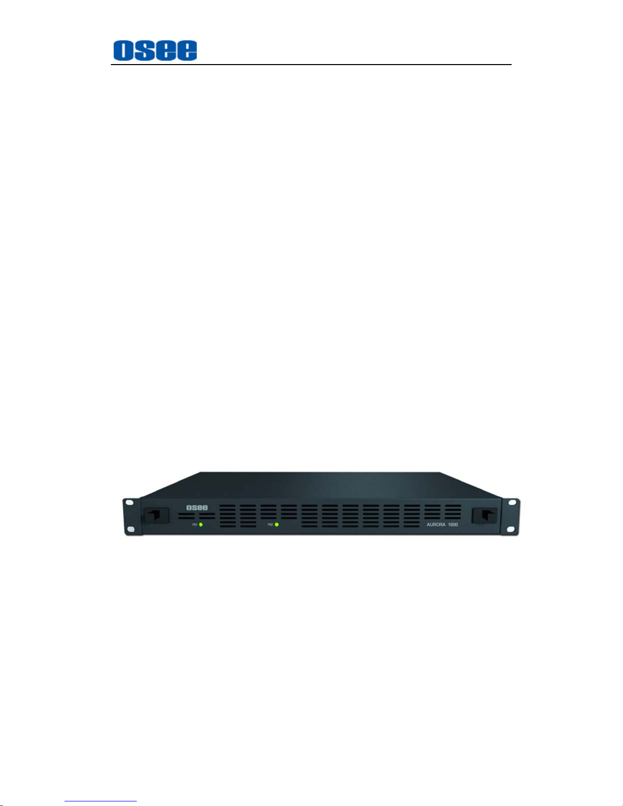
AURORA1600
1U
Multi-image Processor
User Manual
Page 2

Page 3

Product Information
Model:
AURORA1600 1U Multi-image Processor
Version:
V010100
Release Date:
November 5th, 2015
Company
OSEE TECHNOLOGY CO., LTD.
Customer Support
Address:
No.22 Building, No.68 zone, Beiqing Road, Haidian District,
Beijing, China
Post Code:
100094
Tel:
(+86) 010-62434168
Fax:
(+86) 010-62434169
Web:
http://www.osee-dig.com/
E-mail:
Page 4

About this manual
Important
The following symbols are used in this manual:
The further information or know-how for described subjects above which
helps user to understand them better.
The safety matters or operations that user must pay attention to when using
this product.
Contents
The user manual applies to the following device types:
AURORA1600
The images of AURORA1600 adopted in the following descriptions.
Any of the different specifications between the device types are elaborated.
Before reading the manual, please confirm the device type.
Page 5

Contents
Contents .......................................................................................................... I
Chapter 1 Product Overview ......................................................................... 1
Chapter 2 Safety ............................................................................................. 5
Chapter 3 Unpack and Installati on ............................................................... 7
Chapter 4 AURORA1600 Features .............................................................. 11
4.1
Front Panel Features ........................................................................ 1 1
4.2
Rear Panel Features .......................................................................... 11
4.2.1 Arrangement of Rear Connectors ................................................... 12
4.2.2 Operations of Rear Panel ............................................................... 12
4.2.3 Timing ............................................................................................. 18
4.3
Control Access .................................................................................. 19
Chapter 5 Specifications ............................................................................. 21
Page 6

Page 7
Product Overview
1
Chapter 1 Product Overview
This article is mainly about AURORA1600, developed by OSEE with high
intelligent, which applied the 1U Multi-image Processor, which performs
multi-channels input signals displayed on one screen for surveillance. It
attaches, switches and zooms the video sources, and provides ideal visual
effect, flexible operation environment and easiness for configuration and
maintenance.
The device has the compact module structure, supports up to 16 channels of
3G/HD/SD-SDI inputs, and up to 4 channels of HDMI/SDI outputs, the
resolution is up to 1920*1080. Signals can be appointed to any output for
display freely, and it allows the user easily to set up a display system in 1U
frame with 4 inputs, 8 inputs, 12 inputs or 16 inputs.
The device integrates an internal control software to connect to and configure
the controller. You can configure multi-walls and multi-scene with the input
video sources, and set them at any position and in arbitrary size in the
operating interface of the software. Each video window has adequate
resolution to show very high quality frame effects. The software is a WYSIWYG
editor and easy to use.
The 1U Multi-image Processor and its inner control software compose the
Multi-image system, and it is widely used in studio, transmission control rooms,
video conference center, general control center, TV Stations and so on.
Figure 1-1 The Module of 1U Multi-image Processor
1U Multi-image Processor supports the following features:
Features
Using professional case for high reliability
Using 1U compact module structure
The window of a video source can be moved from one screen to
another screen in real time
Support the general video formats and the inputs are adaptive
Page 8
Product Overview
2
Support up to 1920*1080 through one single output interface
Support up to 16 displays in a single screen
Support up to 4K resolution through four combined output interfaces
per 50/60 frame rate
All modules are redundant designed, and support online replacement
Signals can be appointed to any output for display flexibly
Support dual power supply. It is usually load balanced when the power
supply is normal, and once there is a fault in power supply, it will power
on the redundant power to keep persistent
Provide Video/Audio detection and alarming: video loss, video freeze,
video black, audio silence, and audio overload
Provide various detections on modules, temperature and power supply
Support SNMP for native and remote users to configure modules
Functionality
Support dual UMD, dual TALLY, and up to 8 channels of UV audio
meter, and support dynamic TSL protocol
Support 16 channels of GPI input and 4 channels of GPO output
Support several timing methods: LTC timing, native network timing
Support UMD edit and display
Support format display of input signal and AFD information display
Support Network control
Support several types of timers: analog clock timer, digital clock timer,
countdown timer, and digital data timer.
Support TC
Support various operation methods: remote control panel, web control
and computer control
Support models switching, signal sources switching and Full Screen
functions
Topology Chart
The topology chart for this unit is shown as in Figure 1-:
Page 9

Product Overview
3
SDI HDMI
SDISDISDI
Remote Control Computer
Router
Figure 1-2 The Topology of AURORA1600
Page 10

Page 11
Safety
5
Chapter 2 Safety
FCC Caution:
Any Changes or modifications not expressly approved by the party responsible
for compliance could void the user's authority to operate the equipment.
This device complies with part 15 of the FCC Rules.
Operation is subject to the following two conditions: (1) This device may not
cause harmful interference, and (2) this device must accept any interference
received, including interference that may cause undesired operation.
Note: This equipment has been tested and found to comply with the limits for a
Class B digital device, pursuant to part 15 of the FCC Rules. These limits are
designed to provide reasonable protection against harmful interference in a
residential installation. This equipment generates uses and can radiate radio
frequency energy and, if not installed and used in accordance with the
instructions, may cause harmful interference to radio communications.
However, there is no guarantee that interference will not occur in a particular
installation. If this equipment does cause harmful interference to radio or
television reception, which can be determined by turning the equipment off and
on, the user is encouraged to try to correct the interference by one or more of
the following measures:
Reorient or relocate the receiving antenna.
Increase the separation between the equipment and receiver.
Connect the equipment into an outlet on a circuit different from that to which
the receiver is connected.
Consult the dealer or an experienced radio/TV technician for help.
Page 12
Safety
6
Warnings:
Read, keep and follow all of these instructions for your safety. Heed all
warnings.
Multi-image Processor
Upgrading of the device is subject to change without notice.
Contact your Customer Service representative if parts are missing or
damaged.
Position
Do not block any ventilation openings.
Do not use this unit near water.
Do not expose the unit to rain or moisture.
Do not install near any heat sources such as radiators, heat registers,
stoves, or other apparatus (including amplifiers) that product heat.
A nameplate indicating operating voltage, etc., is located on the rear
panel.
The socket-outlet shall be installed near the equipment and shall be
easily accessible.
Page 13
Unpack and Installation
7
Chapter 3 Unpack and Installation
Unpack
When unpacking the components of this switcher, please verify that none of
the components listed in Table 3-1 are damaged or lack. If there is any missing,
contact your distributors or OSEE for it.
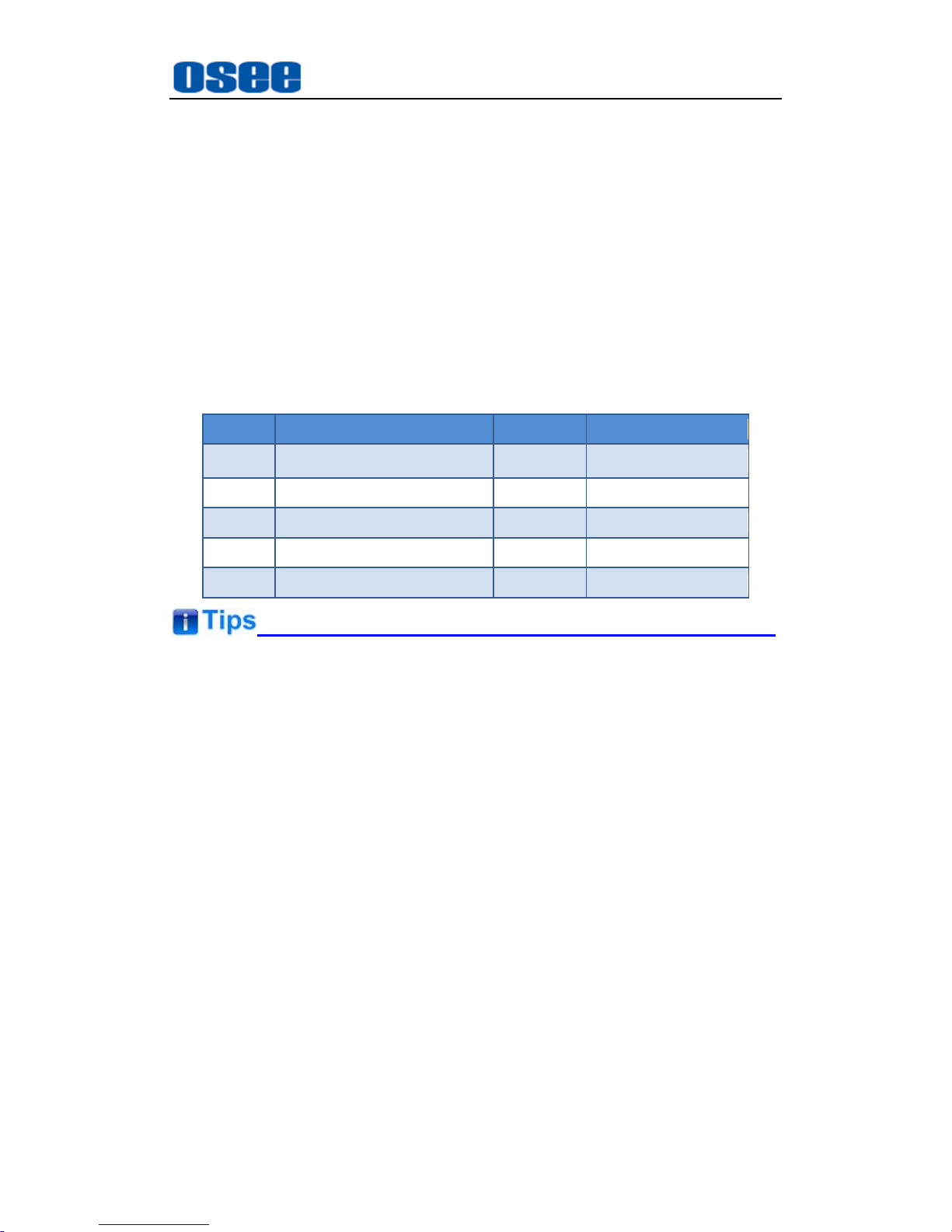
Table 3-1 Packing List
No. Item Quantity Comments
1 Multi-image Processor 1
AURORA1600
2 Power cord 1
3 Attachments 1
4 User manual 1
5 warranty card 1
About Unpacking and Shipping
This product was carefully inspected, tested, and calibrated before
shipment to ensure years of stable and trouble-free service. Before
you install this unit, do the followings:
Check the equipment for any visible damage that may have
occurred during transit.
Confirm receipt of all items on the packing list.
Contact your dealer if any item on the packing list is missing.
Contact the carrier if any item is damaged.
Remove all packaging material from the product before you install
the unit.
Retain at least one set of the original packaging materials, in the
event that you need to return a product for servicing.
Page 14
Unpack and Installation
8
If the original package is not available, you can supply your own
packaging as long as it meets the following criteria:
The packaging must be able to withstand the product’s weight.
The product must be held rigid within the packaging
There must be at least 5 cm of space between the product and the
container.
The corners of the product must be protected.
Ship products back to us for servicing prepaid and, if possible, in the
original packaging material. If the product is still within the warranty
period, we will return the product prepaid after servicing.
Installation
1. Prepare for installation
Make sure you have prepared the followings before mount the converter:
Inspect for any apparent physical damage that may have occurred in
transit.
Make sure you have received all the components listed in packing list.
if there are any anti-static package or other packages, please take off
them.
Keep the package in case of future usage.
The safety matters or operations that user must pay attention to when using
this product.
Ensure that all handling precautions are taken to avoid electrostatic
discharge or other damage to sensitive electronic components. Wear an
earth strap and perform all PCB assembly at an appropriate anti-static work
station. Follow the instructions carefully to fit the modules.
2. Install AURORA1600in your desired location of a standard EIA
Page 15
Unpack and Installation
9
equipment rack. Adequate ventilation is required when installed to
prevent possible damage to the AURORA1600 components.
3. Connect required cables for signal input and output.
4. Connect power source using the included power cord.
5. Connect the power cord to the rear panel.
6. Fasten the power protect accessory.
7. As a final step, power AURORA1600 on.
Restore the default IP setting
AURORA1600 provides an Ethernet port for connecting with a computer
to access the network control page or run the device control tool to modify
the network settings. The default IP address of AURORA1600 is
192.168.1.70.
Restore the default IP setting by short-circuit two pairs of the
corresponding pins of RS422 interface at the rear panel.
The instructions are as below:
Operations:
Firstly, power down the AURORA1600 device, insert a network cable
(called as Restore cable) with a RJ45 plug into the RS422 interface.
Short-circuit the two pairs of corresponding pins of RS422 interface:
Pin3(Rx-) and Pin5(Tx-), Pin4(Rx+) and Pin6(Tx+) by twisting the
corresponding wires of the network cable.
Secondly, power on the AURORA1600 and keep it running for at least 60
seconds, thus, the IP address of AURORA1600 will be restored to the
default one.
At last, power off the AURORA1600 again, and pull out the network cable
from the RS422 interface, then power on the AURORA1600, it will run
normally.
Refer to “4.2.2-7 Operations of Rear Panel-RS422” for the details about
RS422 interface of AURORA1600.
Page 16

Page 17
AURORA1600 Features
11
Chapter 4 AURORA1600 Features
This chapter describes the features of AURORA1600.
4.1 Front Panel Features
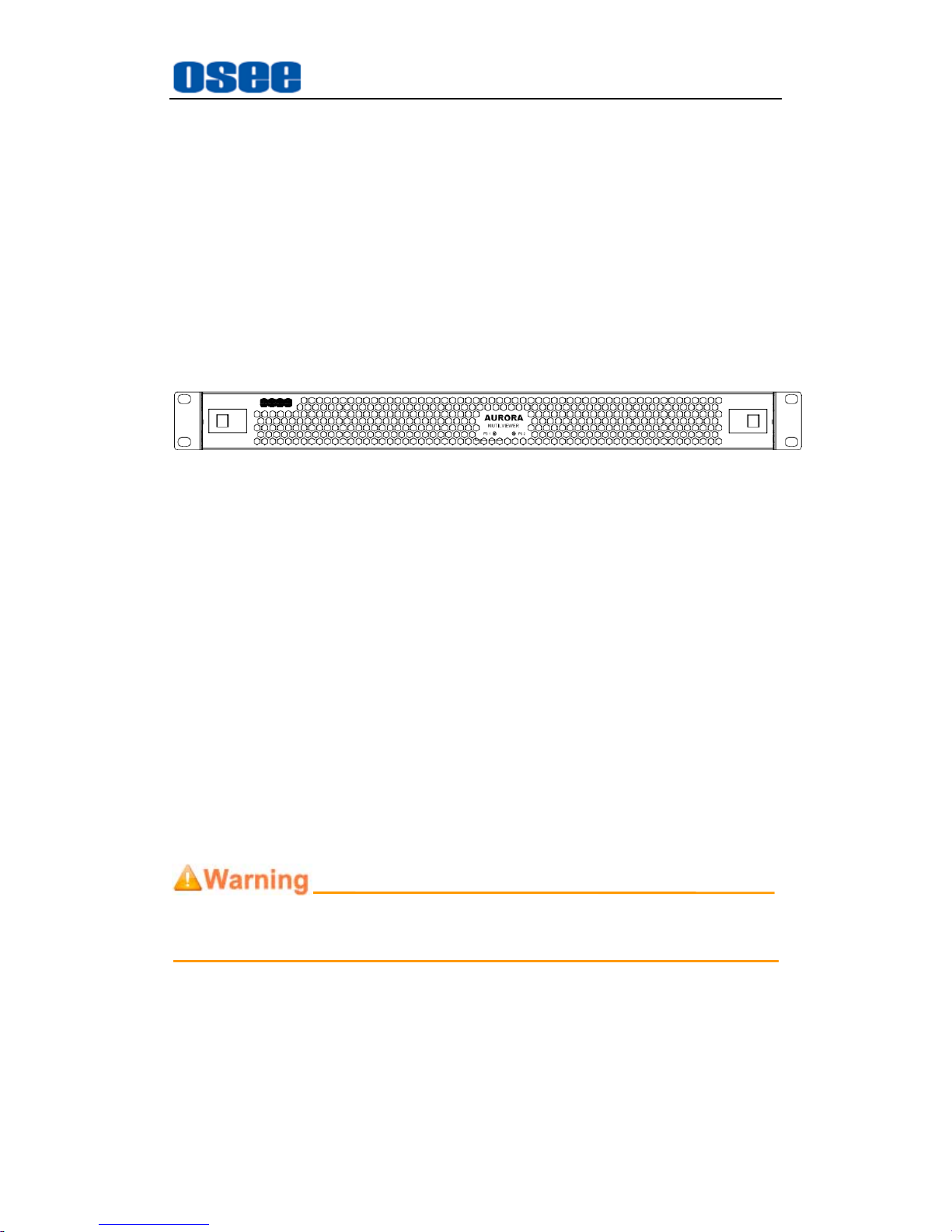
There are two indicators in the center of the front panel, as shown in
Figure 4.1-1
Figure 4.1-1 the Buttons in Front Panel
1. Production Information
It shows the basic information of the production: LOGO and model.
2. PS1 Indicator
It is used to indicate the PS1 power on or off.
3. PS2 Indicator
It is used to indicate the PS2 power on or off.
The Multi-image Processor performs the power supply, input, output and
control functions through the corresponding modules, and you should
make sure the module has been inserted to the correct slot in the frame.
Facing at the direction of the front panel, the arrangement sequence of the
modules from left to right is power supply module, input module, control
module and output module. Each slot has an attribute, you can see the
slots are different after you dismount the front panel.
Make sure the module matches the slot!
4.2 Rear Panel Features
It will introduce the arrangement and the operations of the interfaces in rear of
the panel in the following.
Page 18
AURORA1600 Features
12
4.2.1 Arrangement of Rear Connectors
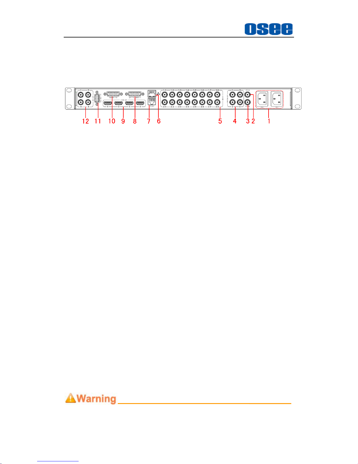
As shown in Figure 4.2-1, AURORA1600 provides the various connectors
for power supply, input, output and control, the details are as below:
Figure 4.2-1 The Rear Connector of AURORA1600
1. Power Input: PS1, PS2
2. LTC IN
3. REF IN
4. Switch Output: SWITCH OUTPUT1~ SWITCH OUTPUT4
5. Video Input: SDI IN 1~16
6. Ethernet
7. RS422
8. GPI & GPO interface: GPI 1~16 & GPO 1~4
9. HDMI Output: HDMI OUT1~HDMI OUT4
10. Audio Input: AUDIO IN 1~16
11. Audio Output: AUDIO OUT 1~4
12. Video Output: SDI OUT 1~4
4.2.2 Operations of Rear Panel
The details of these interfaces at the rear panel are described as below:
1. Power Input
It is used to supply AC power. There are two power input interfaces, they
are redundant, and the specification is 100-240V, 50/60Hz, 100W. They
are labeled as PS1, PS2 separately. The corresponding indicators are at
the front panel. If the light is green, the device is powered on, and if the
light is off, the device is powered off.
Only use the adapter and the power cord specified by the manufacture for
Page 19
AURORA1600 Features
13
your safety!
2. LTC Input (BNC)
It provides one LTC input interface to connect to a LTC timing device, it is
labeled as LTC IN. The LTC timing code is used to time the analog clock
timer or digital clock timer.
3. REF Input (BNC)
It provides one reference input interface, it is labeled as REF IN. Connect
a synchronous signal to realize gen lock to ensure the coincidence of
signals in time at a combining or switching point.
4. Video Output (BNC)
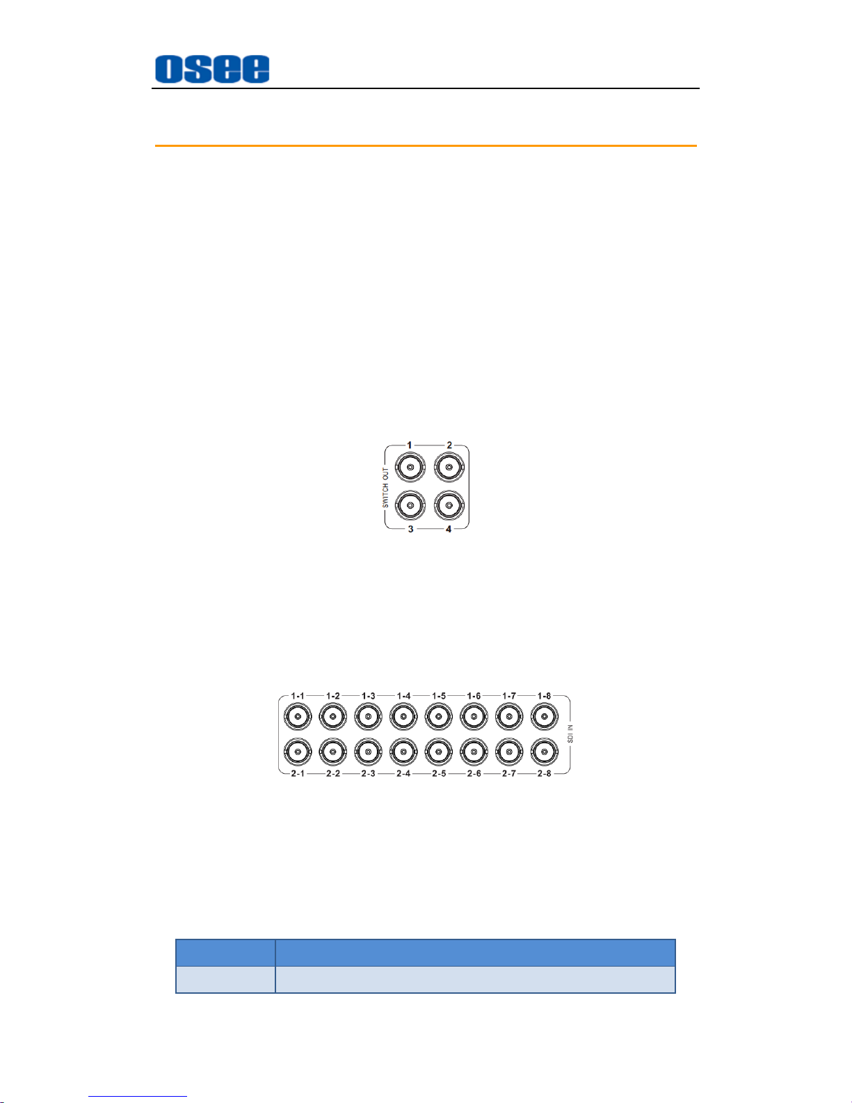
It provides four switch output interfaces, they are labeled as SWITCH
OUT1~SWITCH OUT4. Set any one of the input signals as a switch out
signal to loop it out by tool software.
Figure 4.2-2 Video SWITCH Output Connector
5. Video Input (BNC)
It provides 16 SDI input interfaces, they are labeled as SDI IN 1~16. The
SDI input interfaces are adaptive to 3G/HD/SD-SDI video signals, and
supports embedded audio.
Figure 4.2-3 SDI Video input Connector
The SDI IN interface supports the following resolutions, as shown in Table
4-1:
Table 4-1 The Resolutions of the SDI Interfaces
Name Resolutions
Input formats SD-SDI: 525i60, 625i50
Page 20
AURORA1600 Features
14
Name Resolutions
HD-SDI: 720p50/59.94/60, 720p23.98/24/25/29.97/30,
1080i50/59.94/60, 1035i59.94, 1035i60,
1080p23.98/24/25/29.97/30, 1080sf23.98/24
3G-SDI: 1080p50/60/59.94
6. Ethernet (RJ-45)
It provides one 10/100M Ethernet interface which is used to connect with a
computer to access the network control page or run the device control tool
to modify the network settings.
The default IP address of AURORA1600 is 192.168.1.70.
Restore the default IP setting by short-circuit two pairs of the corresponding
pins of RS422 interface at the rear panel. Refer to “Chapter 3 Unpack and
Installation-- Restore the default IP setting” for the details.
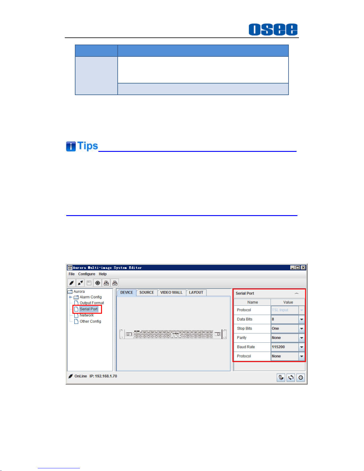
7. RS422(RJ-45)
It offers one RS422 interface to set as TSL in AURORA control software.
Set it in Device Configuration WindowSerial PortProperties window,
as shown in Figure 4.2-4:
Figure 4.2-4 The Application of RS422 Connector
Page 21
AURORA1600 Features
15
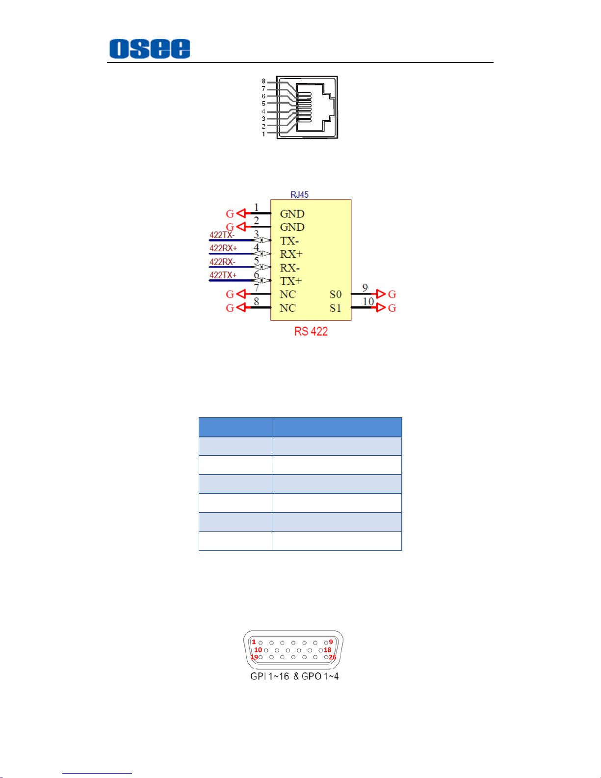
Figure 4.2-5 The Pins Sequence of RS422 Connector
Figure 4.2-6 The Pins Sequence and Functionalities of RS422
Connector
Table 4.2-2 The Relationship of Pins and Values for RS422
Pins Value
1,2 GND
3 Tx-
4 Rx+
5 Rx-
6 Tx+
7,8 GND
8. GPIO(DB26)
It provides one GPIO interface to realize the remote control function, and
you can set a function value to each appointed pin. The relationship of
pins and values for GPIO is as shown in Table 4-3:
Figure 4.2-7 The Pins Sequence of GPIO Connector
Page 22
AURORA1600 Features
16
Table 4-3 The Relationship of Pins and Values for GPIO
Pins Value
Pin1~Pin16 GPI1~GPI16
Pin17~Pin22 GND
Pin23 GPO4
Pin24 GPO3
Pin25 GPO2
Pin26 GPO1
9. Video Output Interface (HDMI)
It provides 4 video output interfaces to receive and send HDMI/DVI
signals. The signal loops out, and supports embedded audio and HDCP.
using HDMI-TypeA connector.
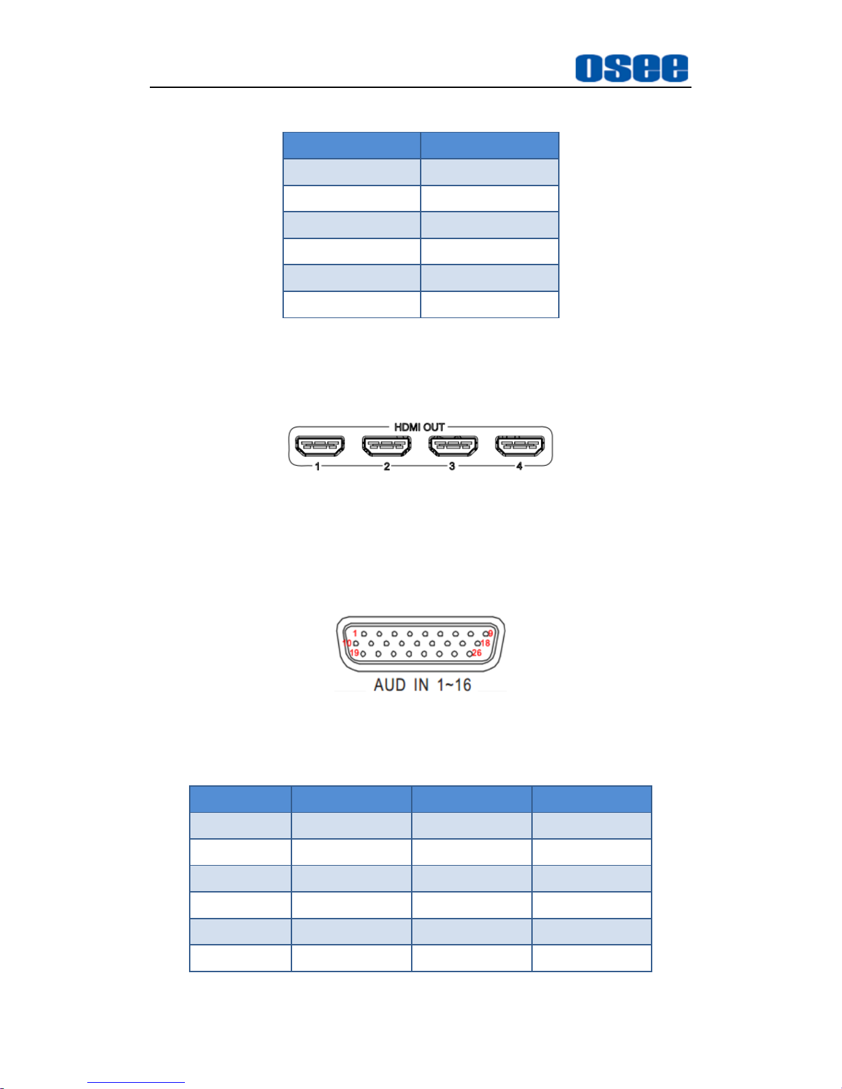
Figure 4.2-8 The HDMI Output Interface
10. Audio Input Interface (DB26)
It provides one audio input interface, it is labeled as AUD IN 1~16. It
supports 16 channels of analog audio input signals.
Figure 4.2-9 The Audio Input Interface
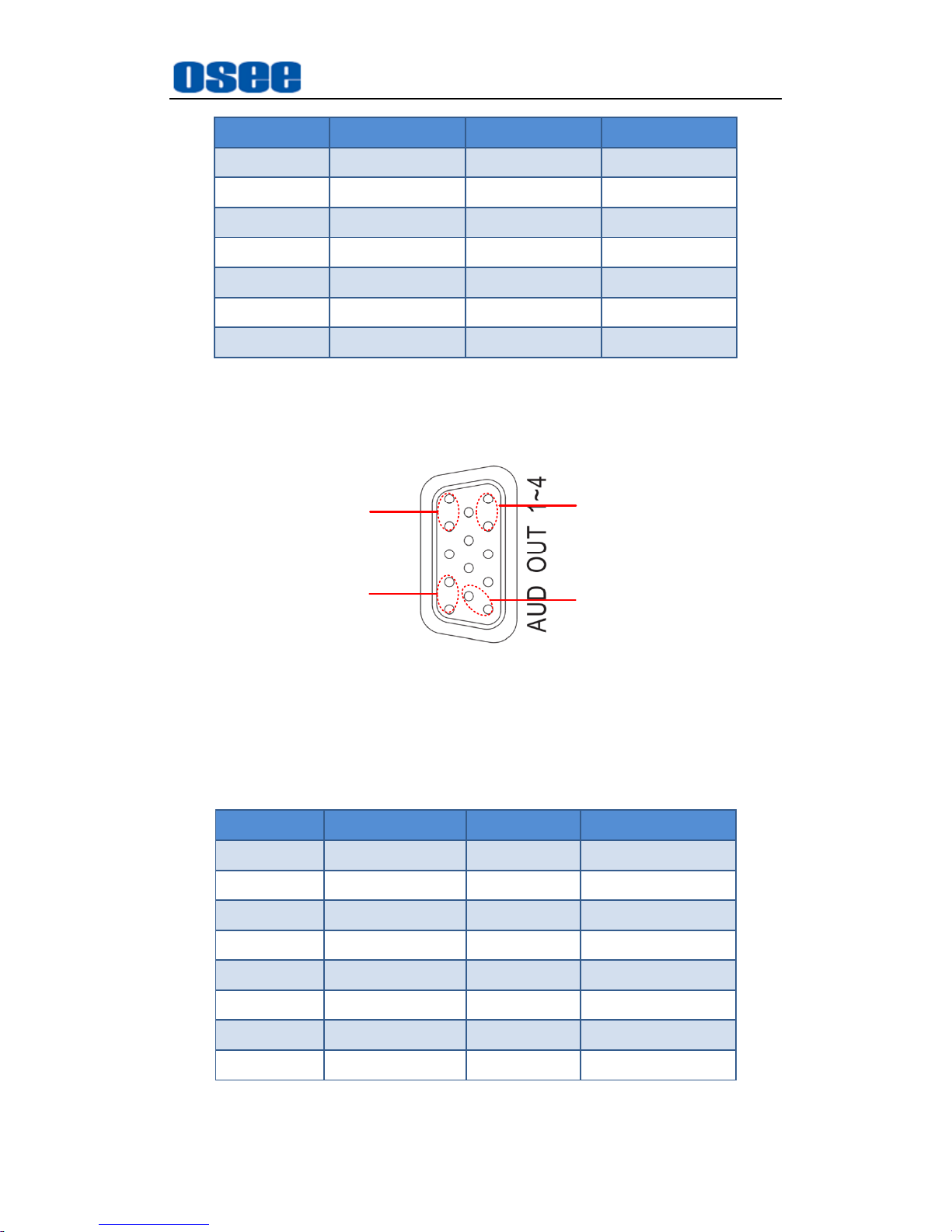
Table 4-4 The Relationship of Pins and Values for AUD IN
Pins Value Pins Value
Pin1 AUDIO IN1 Pin14 GND
Pin2 AUDIO IN10 Pin15 AUDIO IN7
Pin3 GND Pin16 AUDIO IN11
Pin4 AUDIO IN2 Pin17 GND
Pin5 AUDIO IN3 Pin18 AUDIO IN8
Pin6 GND Pin19 AUDIO IN9
Page 23
AURORA1600 Features
17
Pins Value Pins Value
Pin7 AUDIO IN15 Pin20 AUDIO IN13
Pin8 AUDIO IN4 Pin21 GND
Pin9 GND Pin22 GND
Pin10 AUDIO IN5 Pin23 GND
Pin11 GND Pin24 AUDIO IN16
Pin12 AUDIO IN14 Pin25 GND
Pin13 AUDIO IN6 Pin26 AUDIO IN12
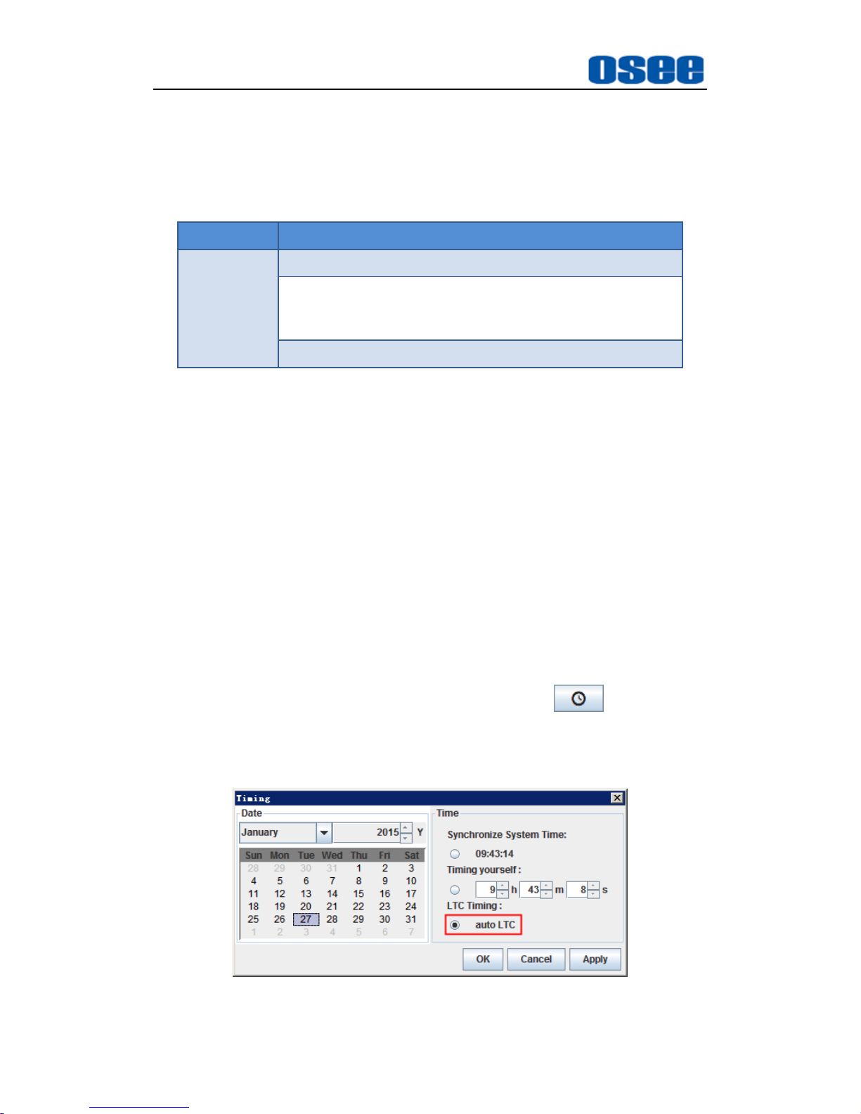
11. Audio Output Interface (DB26)
It provides one audio output interface, it is labeled as AUD OUT 1~4. It
supports 4 pairs of audio output signals, as shown in Figure 4.2-10.
LINEC
LINEA
LINEB
LINED
1
6
11
5
10
15
Figure 4.2-10 The Audio Output Interface
The relationship of pins and values for AUD OUT is as shown in Table 4-5:
Table 4-5 The Relationship of Pins and Values for AUD OUT
Pins Value Pins Value
Pin1 LINEC-R Pin9 GND
Pin2 LINEC-L Pin10 LINEA-R
Pin3 GND Pin11 LINED-R
Pin4 GND Pin12 LINED-L
Pin5 LINEA-L Pin13 GND
Pin6 GND Pin14 LINEB-L
Pin7 GND Pin15 LINEB-R
Pin8 GND
12. Video Output (BNC)
Page 24
AURORA1600 Features
18
It provides 4 SDI output interfaces, they are labeled as SDI OUT 1~4. The
SDI Output interface supports the following resolutions, as shown in Table
4-6:
Table 4-6 The Resolutions of the SDI Output Interfaces
Name Resolutions
Input formats
SD-SDI: 525i60, 625i50
HD-SDI: 720p50/59.94/60, 720p23.98/24/25/29.97/30,
1080i50/59.94/60, 1035i59.94, 1035i60,
1080p23.98/24/25/29.97/30, 1080sf23.98/24
3G-SDI: 1080p50/60/59.94
4.2.3 Timing
AURORA1600 provides the following timing methods: LTC and native
timing (administration side).
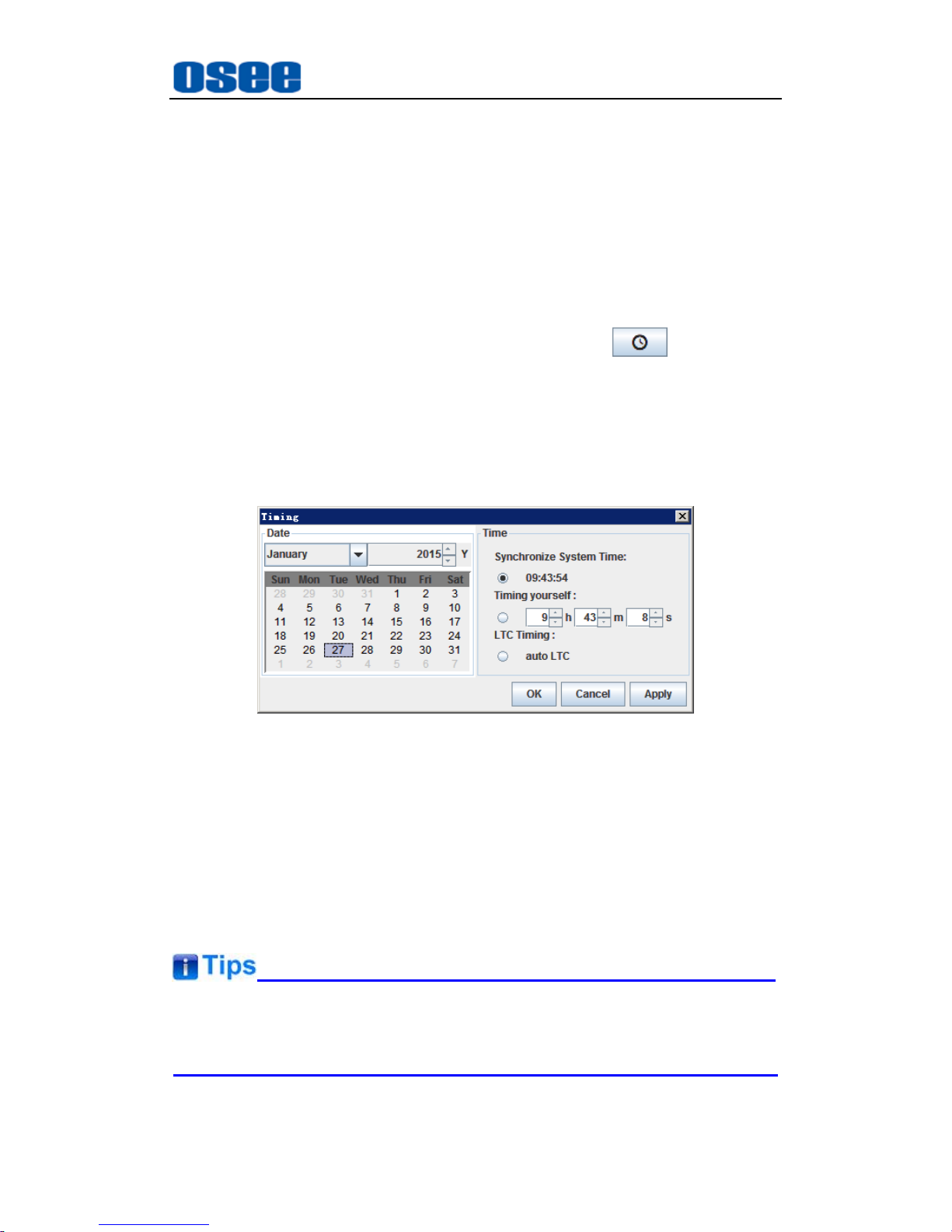
1. LTC Timing
Use LTC timing through LTC port, the conditions are as below:
(1) Connect a LTC timing device through the LTC port. The LTC external
device receive a timecode input signal to keep synchronous with the
system clock, and the timecode conforms to the SMPTE12M
(EBU-3259-E) standard.
(2) Timing operation: click the manual timing button , it will pop up
the timing window, select LTC timing in the timing dialog box, as shown
in Figure 4.2-11:
Figure 4.2-11 Selection of Timing Method-LTC
Page 25
AURORA1600 Features
19
2.
Local Timing
Use the local computer connected through the Ethernet port to time with
AURORA1600.
(1) Connect a local computer through the Ethernet port (RJ45), using
twisted-pair cables the IP address of the local computer and the
AURORA1600 must be in the same network segment.
(2) Timing operation: click the manual timing button , it will pop up
the timing window, select the Time method as Synchronize System
Time to use the current time, or select as Timing yourself to a
customized time, as shown in Figure 4.2-12, click the manual timing
button to confirm timing with the local time.
Figure 4.2-12 Timing Operation Window
4.3 Control Access
The AURORA1600 is connected to its remote control computer through the
Ethernet interface using the twisted-pair cable. Start up the computer and run
the multi-image control software, and the software will load the information of
the multi-image after setting up the connection.
The multi-image and the remote control computer must be at the same
network segment.
Double click the program AURORA.exe in the installation folder of the
Page 26
AURORA1600 Features
20
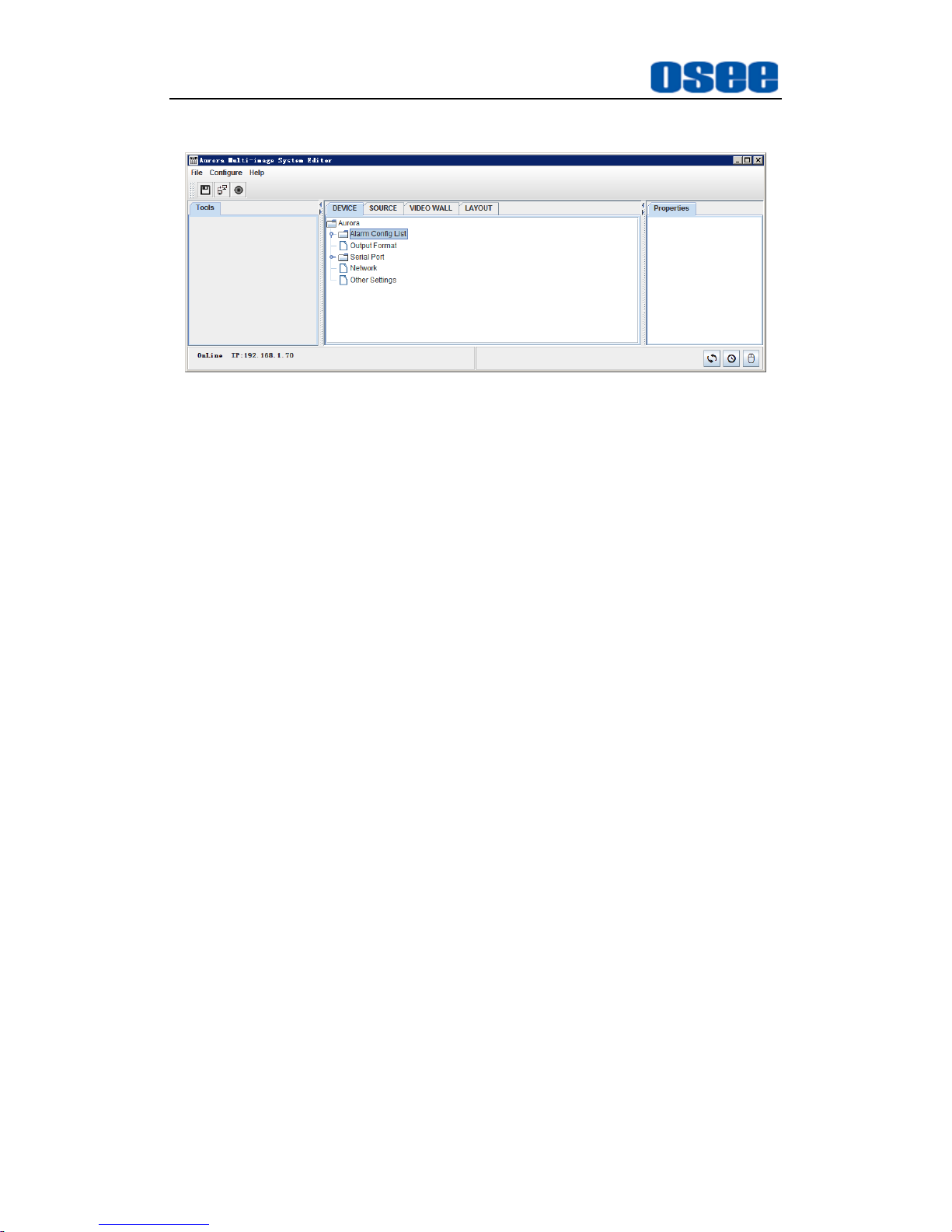
multi-image control software, the software interface is shown in Figure 4.3-1:
Figure 4.3-1 The Interface of the Multi-image Control Software
Refer to "The Manual for the Multi-image Controller Software " for details.
Page 27
Specifications
21
Chapter 5 Specifications
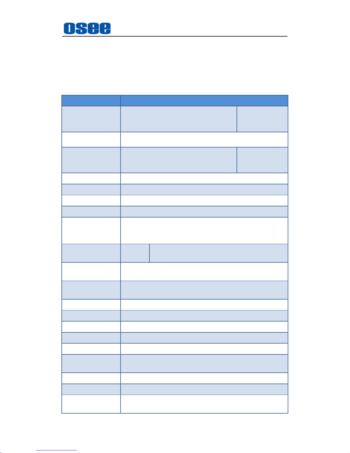
1. Product detailed information
Specification Values
Input characteristic
16 channels of 3G/HD/SD-SDI input
signals
one input
module with 16
input channels
Input module 3G/HD/SD-SDI input signal
Output
characteristic
4 channels of SDI/HDMI output signal
one output
module with 4
output channels
Output module SDI/HDMI output signal
Control Interface GPI/O, LTC, Ethernet, RS422 (TSL)
Display Units Up to 16 displays in a single screen
Control Software AURORA
Working
Environment
Work Temperature: 0~70℃
Work Humility: 10%~90%(no condense)
Height: below 1000 feet (3048 meter) above sea level
Weight(fully
loaded)
1U,6.1kg 465.5(L)×342(W)×44(H)mm
Power
Consumption
100W
Electrical
Characteristics
100-240VAC, 50-60Hz, two redundant power modules
Signal Format NTSC, PAL
Signal Amplitude 1Vp-p+/-3dB
Impedance 75Ω
Return Loss >40 dB to 5 MHz
DC Offset 0V±0.05 V
Frequency
Response
±0.2 dB to 5 MHz
Differential Gain <1%
Differential Phase <1.5°
Video Standard
SMPTE 424M, SMPTE 292M, SMPTE 259M, SMPTE
297M
Page 28
Specifications
22
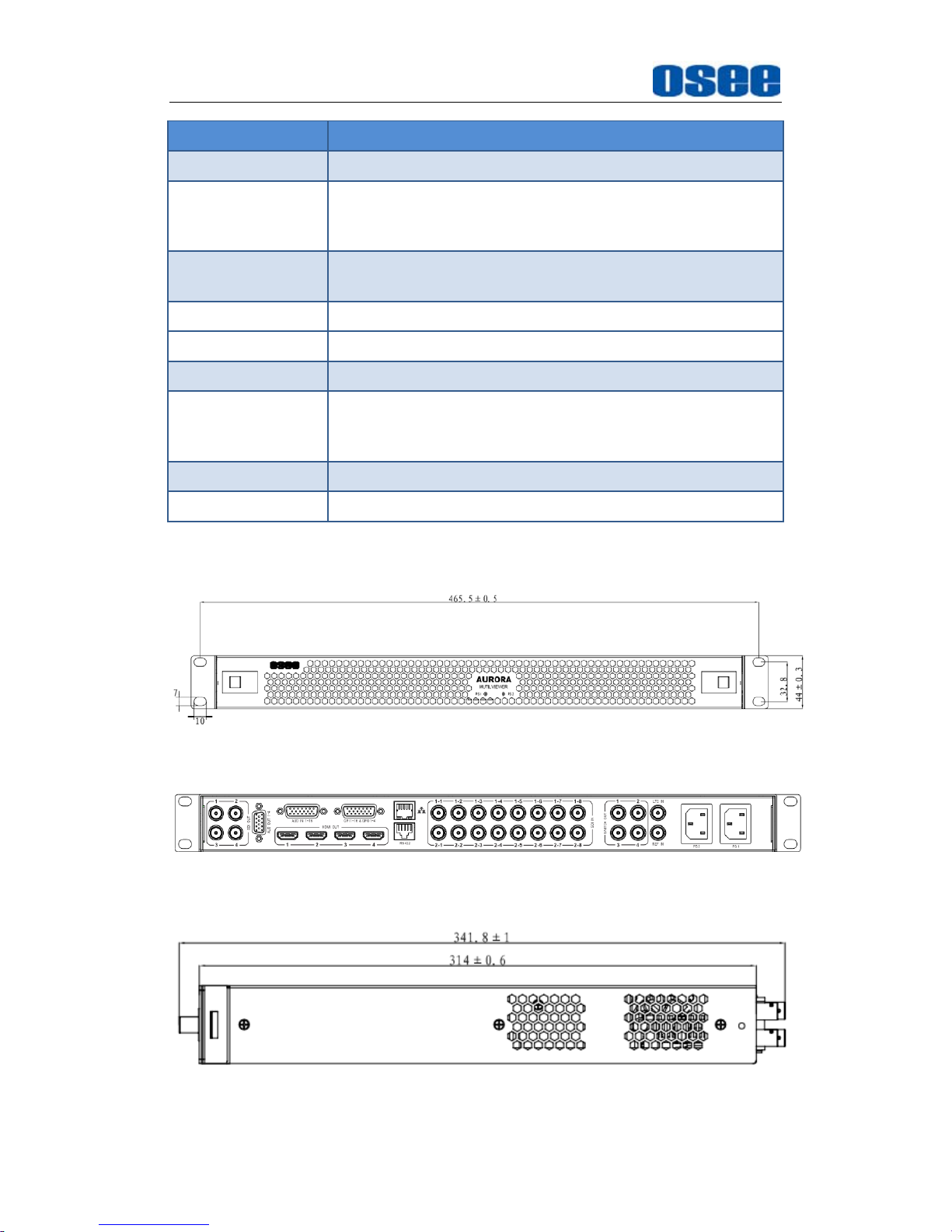
Specification Values
Connector BNC per IEC 169-8
Return Loss
>18 dB 5 to 270 MHz
>15 dB 270 MHz to 1.5 GHz
>10 dB up to 3 GHz
Maximum Signal
Level
800 mV pk-pk 10%
Signal Amplitude 800 mV pk-pk 10%
Overshoot <10%
Jitter <0.2 UI
Rise and Fall Time
<700 ps for SD
<270 ps for 1.5 Gb/s HD
<135 ps for 3 Gb/s HD
Extinction Ratio >8
Back Reflection <-14 dB
2. Product Outline
The outline of AURORA1600 is shown as in the following figures:
Figure 5-1 Front Panel(Unit: mm)
Figure 5-2 Rear Panel(Unit: mm)
Figure 5-3 Side View(Unit: mm)
Page 29
Specifications
23
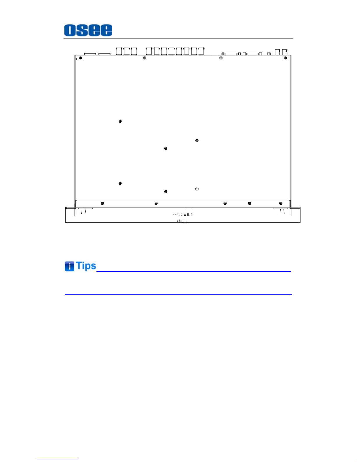
Figure 5-4 Top View(Unit: mm)
Specifications are subject to change without notice.
------------------No Text Below------------------
Page 30

Page 31
FOR MORE INFORMATION PLEASE VISIT: http://www.osee-dig.com/
OSEE TECHNOLOGY CO., LTD.
No.22 Building, No.68 zone, Beiqing Road, Haidian District, Beijing, China
Tel : (+86)010‐62434168,Fax:(+86)010‐62434169
E-mail: [email protected]
 Loading...