

OSEE ACOHD6800 User Manual

ACOHD6800
4X1 Intelligence Switcher
User Manual


Product Information
Model:
ACOHD6800 4X1 Intelligence Switcher
Version:
V010001
Release Date:
March 12th, 2015
Company
OSEE TECHNOLOGY CO., LTD.
Contact Information
Address:
No.22 Building, No.68 zone, Beiqing Road, Haidian District,
Beijing, China
Post Code:
100094
Tel:
(+86) 010-62434168
Fax:
(+86) 010-62434169
Web:
http://www.osee-dig.com/
E-mail:
sales@osee-dig.com

About this manual
Important
The following symbols are used in this manual:
The further information or know-how for described subjects above which
helps user to understand them better.
The safety matters or operations that user must pay attention to when using
this product.
Contents
The user manual applies to the following device types:
ACOHD6800
The images of ACOHD6800 adopted in the following descriptions.
Any of the different specifications between the device types are elaborated.
Before reading the manual, please confirm the device type.

Contents
Contents .......................................................................................................... I
Chapter 1 Product Overview ......................................................................... 1
Chapter 2 Safety ............................................................................................. 3
Chapter 3 Unpack and Installation ............................................................... 5
Chapter 4 Features ...................................................................................... 11
4.1
ACOHD6800 Module Features .......................................................... 11
4.2
Rear Connector Features ................................................................. 13
Chapter 5 Operation and Control ............................................................... 17
5.1
Instructions on Control and Operation ........................................... 17
5.2
Instructions on Parameter Settings ................................................. 18
5.2.1
Parameter Settings ......................................................................... 18
5.2.2
Menu Items ..................................................................................... 19
5.3
LED Indicator ..................................................................................... 26
5.4
Network Control ................................................................................ 28
Chapter 6 Specifications ............................................................................. 35

Product Overview
1
Chapter 1 Product Overview
This article is mainly about ACOHD6800 module, which is a 1RU card that can
be installed in 6800N series frame.
ACOHD6800 4×1 module is an emergency switcher, it offers supervision for
the real-time state of input signal, detection and alarm for video loss, EDH,
freeze frame and black burst. It can manually or automatically switch from the
primary input to the backup input once detecting abnormal signals or alarms,
thus it will keep consistency for the output. It is widely used in studio,
transmission control rooms, TV Stations and so on.
ACOHD6800 4×1 module offers four SD/HD-SDI input signals, one video loop
output with clock recovery, and the primary input IN1 offers a bypass relay
protection for the output. It supports the clean switching technology which is
realize by the internal circuitry, this technology provides continuous video
streams, and ensures a smooth switching without video flashing and audio
noise.
Switch control can be performed automatically or manually via GPI or a
matched remote control panel. In manual mode, switch control can be
undertaken via a remote control panel, or simply via GPI. In automatic mode,
the card will perform switch control based on internal signal analysis with alarm
conditions, and the status of the inputs. You can get the switched results by the
status of the connected remote control panel or the web page on the
connected computer. In automatic mode, you can set the automatic switching
mode, selecting from downward or upward. The IN1 is a particular bypass
channel to ensure continues output in case of a power failure.
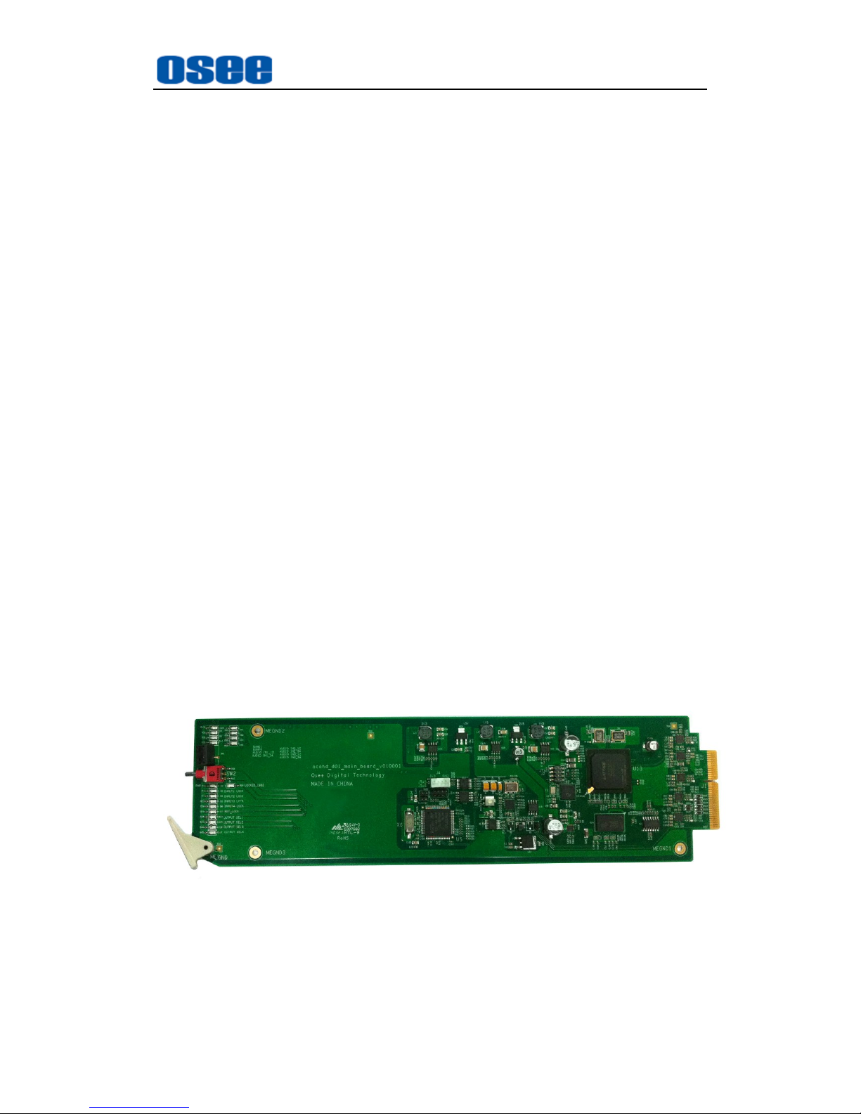
Figure 1-1 The Module of ACOHD6800
ACOHD6800 modules support the following features:
Features
Provides switching among three input HD/SD-SDI signals, and

Product Overview
2
provides one reference input signal, one HD/SD-SDI output
Support selecting control mode between manual control and automatic
control
The automatic mode performs based on signal analysis of video loss,
EDH, freeze frame, black burst and audio supervision.
Build-in automatic horizontal corrector, and adjustable delay
Detecting the trigger of alarm criteria for the control mode switch-over
Support controls through remote control panel, GPIO and RS422
Input IN1 bypass to the output in the event of power failure or module
missing
The input cable equalization automatically
Support clean switching technology
Configures the modules through switches or network control panel
Functionality
Alarms when video lost, static frame or detecting black field
Supports power off memory, the settings will be restored if the module
loses power
Provides frame synchronizer
Supports intelligent protection function in order to avoiding "misuse".
When the input signal is detected abnormal, the switching operation for
output would be invalid.
Product Module
Table 1-1 Input/Output Signals Supported by ACOHD6800
Module Type
Input
Output
ACOHD6800
four HD/SD-SDI video input
one REF input
one HD-SDI loop output with
clock recovery
Signal Flow Chart
The signal flow chart for this unit is shown as in Figure 1-2:
Figure 1-2 The Signal Flow Chart of ACOHD6800

Safety
3
Chapter 2 Safety
FCC Caution:
Any Changes or modifications not expressly approved by the party responsible
for compliance could void the user's authority to operate the equipment.
This device complies with part 15 of the FCC Rules.
Operation is subject to the following two conditions: (1) This device may not
cause harmful interference, and (2) this device must accept any interference
received, including interference that may cause undesired operation.
Note: This equipment has been tested and found to comply with the limits for a
Class B digital device, pursuant to part 15 of the FCC Rules. These limits are
designed to provide reasonable protection against harmful interference in a
residential installation. This equipment generates uses and can radiate radio
frequency energy and, if not installed and used in accordance with the
instructions, may cause harmful interference to radio communications.
However, there is no guarantee that interference will not occur in a particular
installation. If this equipment does cause harmful interference to radio or
television reception, which can be determined by turning the equipment off and
on, the user is encouraged to try to correct the interference by one or more of
the following measures:
Reorient or relocate the receiving antenna.
Increase the separation between the equipment and receiver.
Connect the equipment into an outlet on a circuit different from that to which
the receiver is connected.
Consult the dealer or an experienced radio/TV technician for help.

Safety
4
Warnings:
Read, keep and follow all of these instructions for your safety. Heed all
warnings.
4×1 Switcher
Upgrading of the converter is subject to change without notice.。
Contact your Customer Service representative if parts are missing or
damaged.
Position
Do not block any ventilation openings.
Do not use this unit near water.
Do not expose the unit to rain or moisture.
Do not install near any heat sources such as radiators, heat registers,
stoves, or other apparatus (including amplifiers) that product heat.
A nameplate indicating operating voltage, etc., is located on the rear
panel.
The socket-outlet shall be installed near the equipment and shall be
easily accessible.
Unpack and Installation
5
Chapter 3 Unpack and Installation
Unpack
When unpacking the components of this switcher, please verify that none of
the components listed in Table 3-1 are damaged or lack. If there is any missing,
contact your distributors or Beijing Osee Digital Technology Ltd. for it.
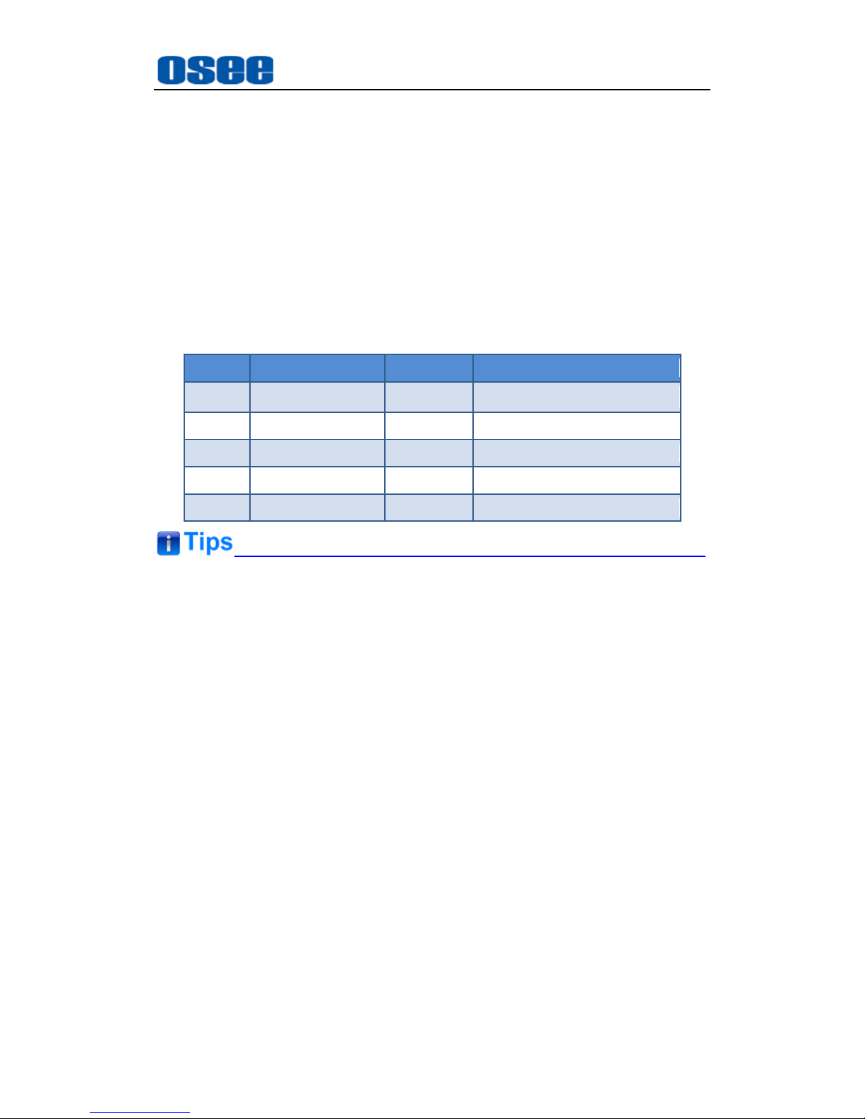
Table 3-1 Packing List
No.
Item
Quantity
Comments
1
Switcher
1
ACOHD6800
2
Rear connector
1
3
Attachments
1
4
User manual
1
5 warranty card
1
About Unpacking and Shipping
This product was carefully inspected, tested, and calibrated before
shipment to ensure years of stable and trouble-free service. Before
you install this unit, do the followings:
Check the equipment for any visible damage that may have
occurred during transit.
Confirm receipt of all items on the packing list.
Contact your dealer if any item on the packing list is missing.
Contact the carrier if any item is damaged.
Remove all packaging material from the product before you install
the unit.
Retain at least one set of the original packaging materials, in the
event that you need to return a product for servicing.
If the original package is not available, you can supply your own

Unpack and Installation
6
packaging as long as it meets the following criteria:
The packaging must be able to withstand the product’s weight.
The product must be held rigid within the packaging
There must be at least 5 cm of space between the product and the
container.
The corners of the product must be protected.
Ship products back to us for servicing prepaid and, if possible, in the
original packaging material. If the product is still within the warranty
period, we will return the product prepaid after servicing.
Installation
1. Prepare for installation
Make sure you have prepared the followings before mount the converter:
Inspect for any apparent physical damage that may have occurred in
transit.
Make sure you have received all the components listed in packing list.
if there are any anti-static package or other packages, please take off
them.
Keep the package in case of future usage.
The safety matters or operations that user must pay attention to when using
this product.
Check out the consumption of module and the maximum power of frame
before installation, the maximum power ratings for different frames are
shown as in Table 3-2.
Ensure that all handling precautions are taken to avoid electrostatic
discharge or other damage to sensitive electronic components. Wear an
earth strap and perform all PCB assembly at an appropriate anti-static work
station. Follow the instructions carefully to fit the modules.
 Loading...