

Oseco VAPRO, VRDI Installation Instructions Manual
Installation Instructions for VAPRO Rupture Disks in VRDI
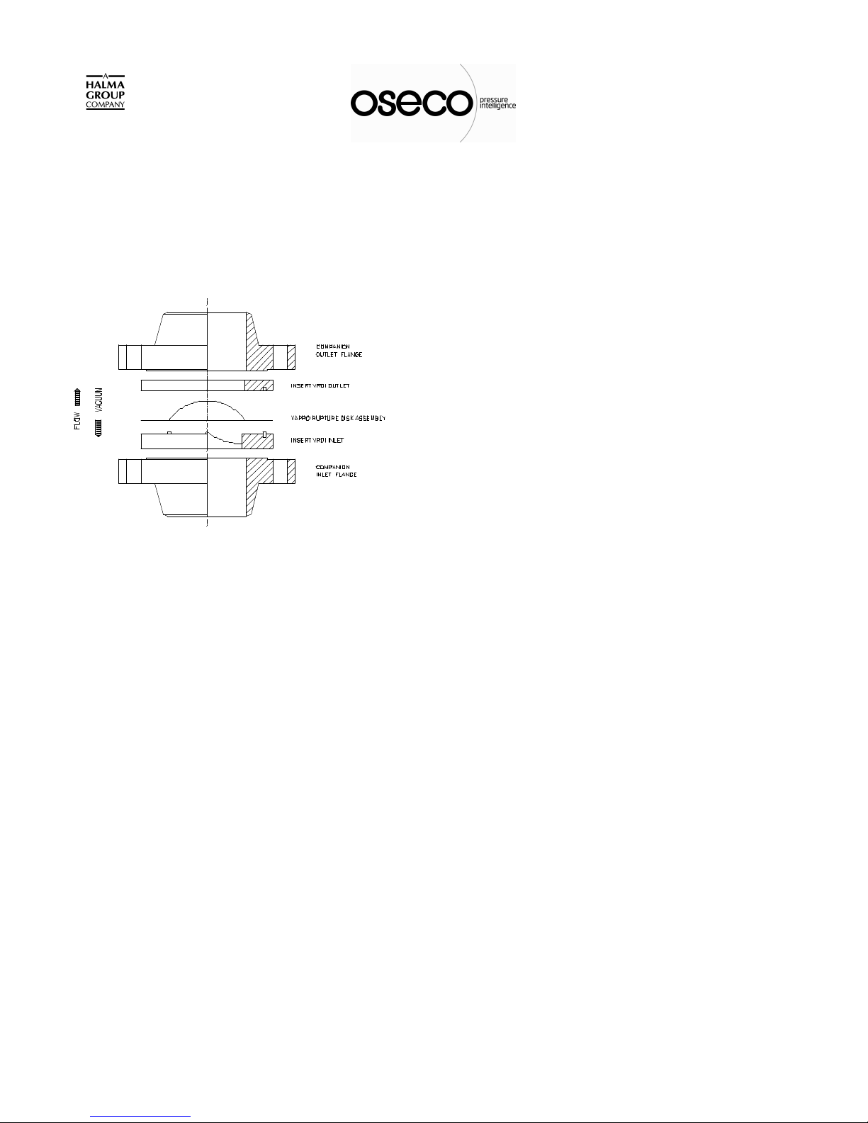
TYPICAL VRDI INSTALLATION
CAUTION
All rupture disk installations should be located to
allow full unrestricted discharge of a burst disk when
over pressure of the system occurs. Never locate a
rupture disk assembly where the discharge from a
burst disk can directly impact personnel or equipment.
Venting of a burst disk discharge must always be
routed to a safe disposal area. Handle burst rupture
disks carefully! Avoid their sharp, jagged edges when
removing same from holder. The knife blades in the
VRDI holder are extremely sharp. Handle holders
very carefully to avoid injury.
IMPORTANT
The VAPRO rupture disk assembly is a dual acting
precision piece of equipment. Handle it with
extreme care. Avoid scratching, bending, denting
or damaging the dome and/or flat seat areas of the
metal disk membrane. Handle the disk by the flat
outer annular seating surfaces and avoid the dome
area as much as possible. Never carry a VAPRO
disk/holder assembly by the name tag alone as
damage to the disk could occur. Do not place tools
or foreign objects on top of the knife blades or
P.O. Box 1327 / 1701 W. Tacoma/ Broken Arrow, OK 74012
“Quality Products to meet Industry Needs”
Holder
holder. The knife blades must be kept very sharp
and free of nicks and defects in order for the disk
assembly to function properly.
RUPTURE DISK HOLDER PREPARATION
1) Loosen and remove flange bolting only after
verifying that the system is de-pressurized. Always
purge toxic and/or dangerous materials area from
any system that is to be opened to a safe disposal.
.
2) Slip the holder insert from between the
companion piping flanges and place on a flat work
surface. Verify that all holder restraints have been
removed. Separate the holder inlet from the outlet
and remove the existing rupture disk assembly.
Telephone: (918) 258-5626 Fax: (918) 251-2809
3) Thoroughly inspect and clean all seating
surfaces of the disk holder. Do not scrape or
scratch any seating surface including the raised
nubbin area! If wiping these surfaces with a clean
cloth and a suitable solvent does not remove
surface residues, fine emery cloth or steel wool may
be utilized. Care should be exercised not to exert
sufficient pressure on the emery cloth or steel wool
to "cut or groove" these surfaces. When in doubt
about the proper condition of these sealing
surfaces, contact OSECO for further instructions.
4) Inspect knife blade points and edges. Knife blade
edges must be razor sharp and free of nicks or
defects. Points must be sharp and undamaged for
the disk assembly to function properly. Contact
OSECO for repair or replacement of dull or
damaged knife blades.
Do not install the Assembly if the blades are
dull, nicked or Damaged.
PS 11.12

Installation Instructions for VAPRO Rupture Disks in VRDI
Holder
RUPTURE DISK INSTALLATION
1) Carefully unpack the rupture disk from its box. If
your disk assembly was packaged with a dome-shaped
shipping protector marked "SHIPPING PROTECTOR -
DO NOT USE", remove it now.
2) Place the Insert VRDI Inlet on flat work surface
with the knife blades pointing up. Place the rupture disk
assembly on the holder, carefully aligning the holes in
the flange portion of the rupture disk assembly with the
alignment pins in the VRDI inlet.
3) Position the Insert VRDI Outlet over the dome of
the rupture disk assembly, carefully aligning the VRDI
Inlet alignment pins with the holes in the VRDI Outlet.
Lower the VRDI Outlet until it engages the VRDI Inlet
alignment pins and rests on the flat outer annular seating
surface of the rupture disk assembly. No binding should
occur during this procedure. If interference occurs,
discontinue installation until the source of the
interference is determined and corrected.
4) Install side bars; however, cap screws should
only be snug, not wrench tight.
5) Check companion flanges and verify that sealing
surfaces are clean, free of corrosion and debris, and are
not bent or warped.
6) Position the Vapro/VRDI assembly within the bolt
circle of companion piping flanges. The concave side of
the rupture disk assembly should face the process or
possible vacuum source. Reinstall studs, nuts and
suitable gaskets. Studs and nuts should be lightly oiled
and free running.
7) Tighten each nut finger tight, then using a
calibrated torque wrench, tighten each nut in a cross
pattern. Use increments of 20% of the recommended
torque value listed in the table below. Do not use torque
values in excess of those shown in the Torque Table as
this may damage the disk or the bite seal on the holder.
VAPRO / VRDI TORQUE TABLE
SIZE
FLANGE
RATING
IN. mm ANSI DIN
RECOMMENDED
TORQUE VALUE
Ft-Lb
3 80 150 - 40 54
- - - 10/16 20 27
4 100 150 10/16 30 41
6
-
8
-
-
10
-
-
12
-
-
150 150 - 40 54
- - 10/16 42 57
200 150 - 50 68
- - 10 52 70
- - 16 35 47
250 150 - 70 95
- - 10 63 85
- - 16 76 103
300 150 - 80 108
- - 10 72 98
- - 16 86 117
N-M
P.O. Box 1327 / 1701 W. Tacoma/ Broken Arrow, OK 74012
“Quality Products to meet Industry Needs”
Telephone: (918) 258-5626 Fax: (918) 251-2809
PS 11.12
 Loading...