

Page 1
T- SERIES LCR INSTALL GUIDE
Page 2
BLACK T-SERIES LCR INSTALL GUIDE
TV
BLACK T-SERIES LCR INSTALL GUIDE
Preparation:
Tools For Installation Speaker Wire Guide
- Pencil
- Drill
- Tape Measure
- Wire Cutter
- Phillips Screwdriver
- Utility Knife
- Safety Eye Wear
- Gloves
- Sandpaper
Considerations
- Where is the best place to install the speakers?
- Where do the speakers sound the best?
- Separate the speakers 6 - 10 feet apart.
Placement
There are many options for proper speaker placement depending
upon speaker type and application. It’s important to carefully plan the
placement of your speakers, as installation requires that you cut a
hole in your wall or ceiling.
18AWG minimum - for distances up to …………………. 10 ft
16AWG - from …………………………………..…... 10 to 50 ft
14AWG - from …………………………………...… 50 to 100 ft
Mounting
Tighten the mounting brackets by simply turning the screws on
the front of the speaker bafe slowly clockwise. The quick-turn
mounting system and frame will “sandwich” or clamp around the
dry-wall to hold the speaker securely in place once fully tightened
to the locked position. (See Diagram 3.)
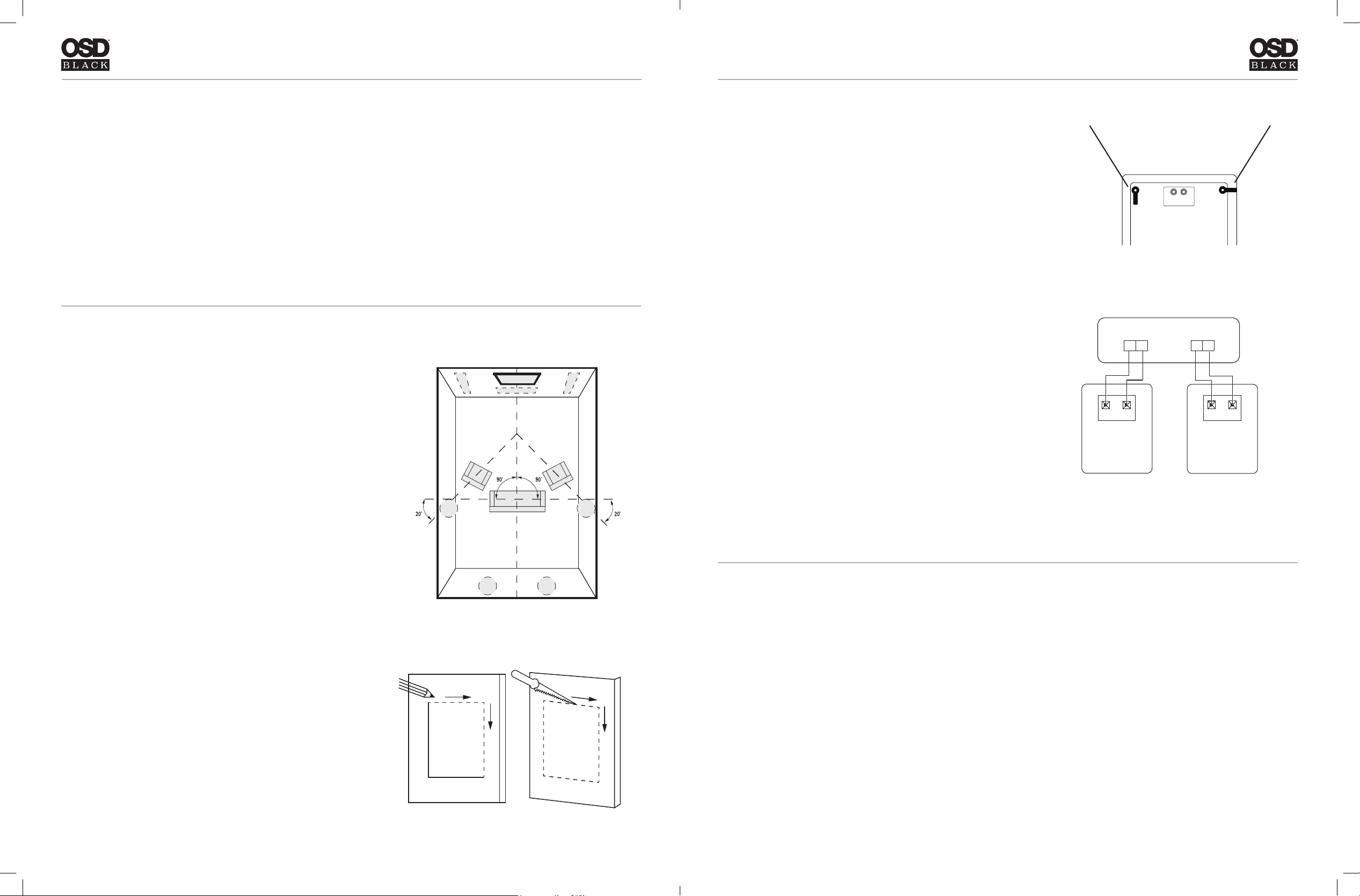
Connection
When connecting any speakers to the amplier or receiver, always
make sure the power is off. Locate the connection terminals
on the back of your receiver or amplier. Always make sure to
connect audio out from the back of your receiver or amplier to the
speakers. (See Diagram 4.)
NOTE: Not all Amplier/Receivers can safely play more than one
pair of speakers at once. Please refer to your owner’s manual for
impedance and wattage compatibility.
Diagram 3
Left Out
Rec/Amp
Right Out
+ +
- -
++
--
Locked PositionOpen Position
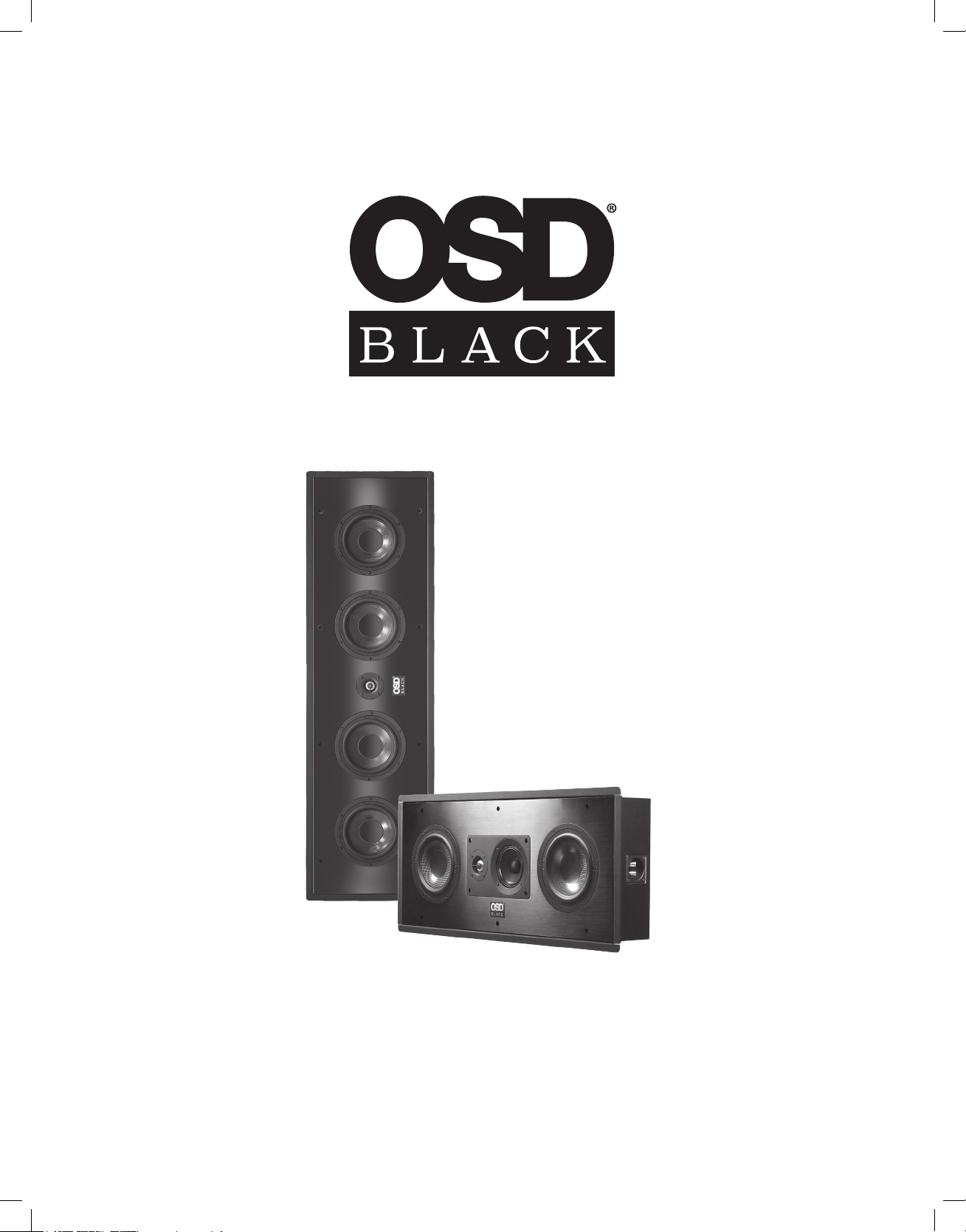
(See Diagram 1.) Typical speaker placement for a 5.1 and 7.1
speaker system.
Installation:
Cut Out
NOTE: This is the most important part of the entire installation.
If you are not certain whether any obstructions exist behind the
desired mounting area, you should start by cutting a small hole in
the center of your penciled mounting hole with a drywall saw.
Using the Cut Out dimensions measure and trace a template on the
wall in the desired location. Cut along the traced line using a drywall
saw or rotary drill. Use a piece of sandpaper to sand down the cut out
edge for a smoother contour. (See Diagram 2.)
Diagram 1
Specications:
T69LCR
• Woofer: Three 6.5” Carbon Fiber Cone Drivers
W/ TPR Surround
• Mid Range: One 6.5” Carbon Fiber Cone Driver
W/ TPR Surround
• Tweeter: One 1” Titanium Dome
• Cloth Magnetic Grille
• Power Handling: 200W
• Sensitivity: 91dB 1w/1m
• Freq Response: 100Hz - 20kHz
• Impedance: 8 ohms
• Dimensions: HxWxD 44.5” x 13.6” x 4.1”
• Cut Out: HxW 42.5” x 11.7”
Left Speaker
Diagram 4
Right Speaker
T68LCR
• Woofer: Three 6.5” Graphite Cone Drivers
W/ TPR Surround
• Mid Range: One 6.5” Graphite Cone Driver
W/ TPR Surround
• Tweeter: One 1” Ceramic Coated Aluminum Dome
• Cloth Magnetic Grille
• Power Handling: 160W
• Sensitivity: 89dB 1w/1m
• Freq Response: 100Hz - 20kHz
• Impedance: 8 ohms
• Dimensions: HxWxD 44.5” x 13.6” x 4.1”
• Cut Out: HxW 42.5” x 11.7”
Diagram 2
Page 3

Specications:
BLACK T-SERIES LCR INSTALL GUIDE
T65LCR
• Woofer: Two 6.5” Carbon Fiber Cone Drivers
W/ TPR Surround
• Mid Range: One 4” Paper Cone Driver
• Tweeter: One 1” Titanium Dome
• Cloth Magnetic Grille
• Power Handling: 200W
• Sensitivity: 90dB 1w/1m
• Freq Response: 85Hz - 22kHz
• Impedance: 8 ohms
• Dimensions: HxWxD 29.52” x 12.79” x 4.13”
• Cut Out: HxW 28.38” x 11.65”
T64LCR
• Woofer: Two 6.5” Graphite Cone Drivers
W/ TPR Surround
• Mid Range: One 4” Paper Cone Driver
• Tweeter: One 1” Ceramic Coated Aluminum Dome
• Cloth Magnetic Grille
• Power Handling: 150W
• Sensitivity: 89dB 1w/1m
• Freq Response: 95Hz - 20kHz
• Impedance: 8 ohms
• Dimensions: HxWxD 29.52” x 12.79” x 4.13”
• Cut Out: HxW 28.38” x 11.65”
WARRANTY
All Optimal Speaker Design speaker products have Limited Lifetime Warranty against defects in materials and workmanship. Proof of purchase
must accompany all claims. During the warranty period Optimal Speaker Design will replace any defective part and correct any defect in
workmanship without charge for either parts or labor Optimal Speaker Design may replace returned speakers with a product of equal value and
performance. In such cases, some modication to the mounting may be necessary and are not Optimal Speaker Designs responsibility.
For this warranty to apply, the unit must be installed and used according to its written instructions. If necessary, repairs must be performed
by Optimal Speaker Design. The unit must be returned to Optimal Speaker Design at the owner’s expense and with prior written permission.
Accidental damage and shipping damage are not considered defects, nor is damaged resulting from abuse or from servicing performed by an
agency or person not specically authorized in writing by Optimal Speaker Design
Optimal Speaker Design sells products only through authorized dealers and distributors to ensure that customers obtain proper support and
service. Any Optimal Speaker Design product purchased from an unauthorized dealer or other source, including retailers, mail over dealers and online sellers will not be honored or serviced under existing Optimal Speaker Design warranty policy. Any sale of product by an unauthorized source
or other manner not authorized by Optimal Speaker Design shall void the warranty on the applicable product.
Damage to or destruction of components due to application of excessive power voids the warranty on those parts. In these cases, repairs will be
made on the basis of the retail value of the parts and labor. To return for repairs, you must email customer service at RMA@audiogeargroup.com
for a Returned Merchandise Authorization (RMA) number# then the unit must be shipped to Optimal Speaker Design at the owner’s expense, along
with a note explaining the nature of service required. Be sure to pack the speaker(s) in a corrugated container with at least 3 inches of resilient
material to protect the unit from damage in transit.
This Warranty Does Not Cover: Damage caused by abuse, accident, misuse, negligence, or improper operation (installation) • Any products that
have been altered or modied • Any product whose identifying number of decal, serial #, etc. has been altered, defaced or removed • Normal wear
and maintenance.
Optimal Speaker Design | Brea, CA | osdaudio.com
Black LCR Manual 6/18
 Loading...