

OSD Audio P8, SS8 Owner's Manual
OSD
R
P8/SS8
AUDIO
P - 8
Speaker Type:
Driver:
Amplifier Power Output:
Frequency Response:
Lowpass Crossover:
Functions:
Inputs:
Dimensions:
Unit Weight:
Warranty:
Powered Stand Alone Subwoofer
8” High Performance Powered Subwoofer
8” Reinforced
100 Watts (RMS)
50Hz - 250 Hz
Adjustable from 50Hz - 250 Hz
Power (On, Off)
Hi Level (Speaker), Line (RCA)
13 3/4” H x 10” W x 13 3/16” D
16.5 lbs.
2 Years
Owner’s Manual
Vertical Placement Horizontal Placement
SS - 8
Speaker Type:
Driver:
Amplifier Power Output:
Frequency Response:
Lowpass Crossover:
Functions:
Optional Vertical Stand:
Inputs:
Dimensions:
Unit Weight:
Warranty:
Low Profile Subwoofer
8” High Performance Low Profile Powered Subwoofer
8” Reinforced
100 Watts (RMS)
50Hz - 250 Hz
Adjustable from 50Hz - 250 Hz
Power (On, Off)
Included
Hi Level (Speaker), Line (RCA)
4” H x 23 3/4” W x 12 1/4” D
20 lbs.
2 Years
Congratulations
on your purchase of a OSD powered subwoofer system. Your new subwoofer is one of the most exciting home entertainment electronic products available,
adding impact and realism to recorded music and the wide variety of movies. Once set-up and properly adjusted, it should give you movie theatre experience
at the comfort of your home.
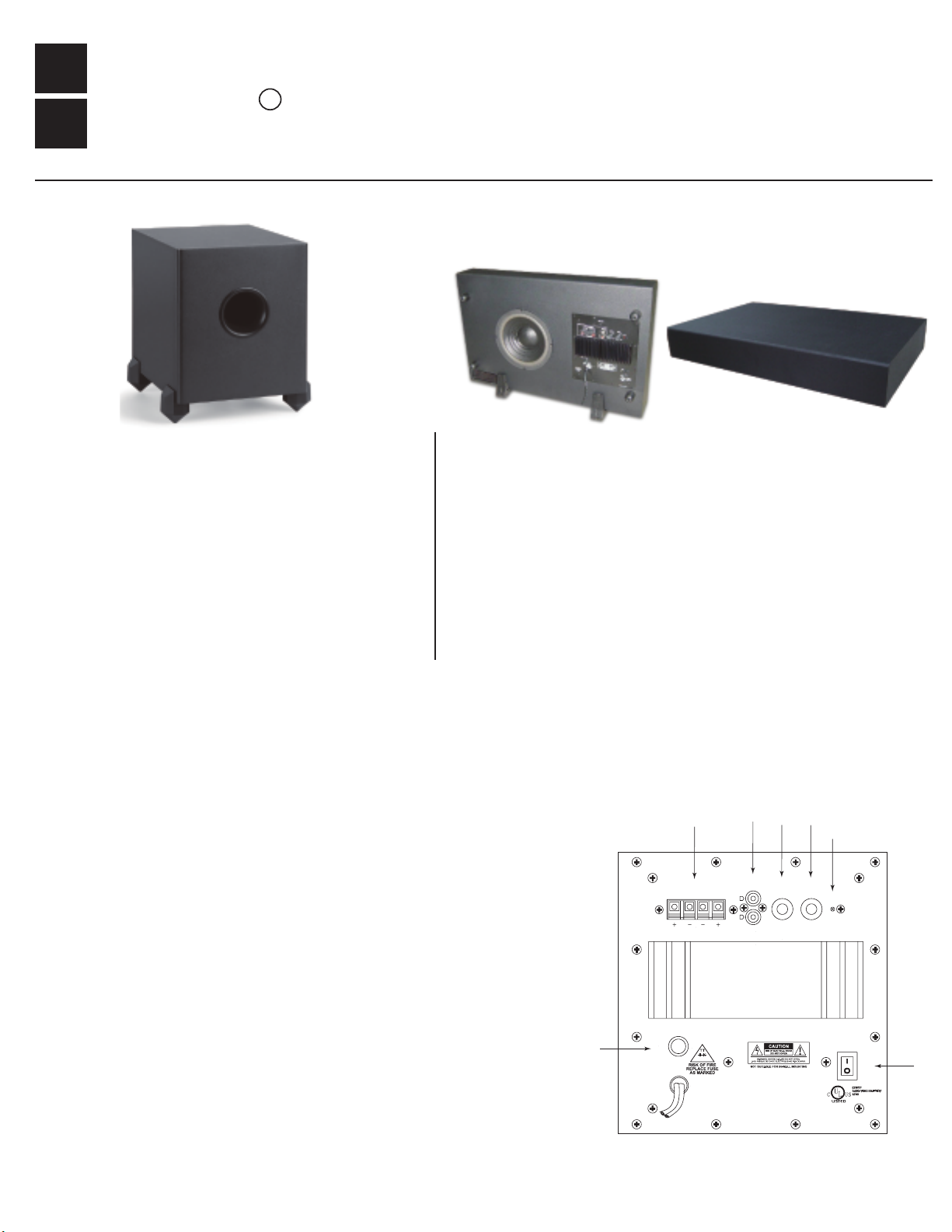
Explanation of Features and Controls
see (figure A)
1)
Power Switch - This two position switch controls the power status of the subwoofer.
Off - Turns the unit off.
On - Turns the unit on regardless of whether a signal is present or not.
2)
Subwoofer crossover - This rotary control adjusts a variable low pass filter to set the upper
frequency at which the output of the subwoofer begins to roll-off. Continuously variable
from 50Hz, it matches the upper frequency characteristics of the subwoofer to the low
frequency response of the main stereo speakers.
3)
Line level input - These RCA phono jacks accept a line level full range signal from the
pre-amplifier output of a receiver or pre-amplifier. This full range signal processed and
amplified to power the subwoofer.
4)
Speaker level input - These spring loaded terminals for speaker wire accept a stereo,
speaker level, full range signal from a receiver or power amplifier. This signal is processed
and amplified to power the subwoofer.
5)
Fuse - For continued protection replace fuse with same type and size listed.
6)
Level control - This rotary control adjusts the level of the subwoofer and is used to balance
its volume with that of the main stereo speakers.
7)
Status LED - This light emitting diode shows the
indicates that the amplifier is plugged in and the power switch is on.
status of the subwoofer electronics. “Red”
4
FROM AMPLIFIER
L
HI LEVEL IN
FUSE 1A/250V
5
1A 250V
120 VAC
100 WATTS
60 HZ
Or
3
L
R
LINE IN
Figure A
6
GAIN
MIN MAX
2
FREQ
50Hz 150Hz
7
POWER
ON
OFF
Made In Chi na
1
Placement or Positionng
Your new subwoofer will work well in a variety of locations. However, placement in your listening room will affect is performance. Since the wavelengths of sound
reproduced by your subwoofer are large compared to its size, those sounds are omni-directional in nature. This means that locating your subwoofer in relation to
your left and right main speakers will not affect the directional cues which they provide. Because the sound you hear is combination of direct sound from the
speaker and reflected sound from the wall, ceiling and floor of your listening room, placement of the subwoofer in relation to room boundaries changes the
balance of what you hear at low frequencies. In that low frequency range, the dimensions of most rooms are comparable to the wavelengths of those sounds. As
sound propagates and reflects in the room, “standing waves” are created at frequencies where the wave length of sound or multiples of the wave length are
equal to one of the dimensions of the room. At your listening position, these standing wave patterns of reflected sound add together in and out of phase causing
large variations in the response that you hear. As a general rule, locating your subwoofer near the corner of the room will increase its overall output, but will excite
standing waves in the room and may result in a more uneven response. Locating your subwoofer along a wall will usually mean less acoustic output but
more
a somewhat smoother response. A middle of the room location would suggest the smoothest response with the least output capability. Of course, any location
will be a compromise between acoustic performance and the aesthetic blend of the subwoofer enclosure with the decor and furnishings of your room. Don’t be
afraid to experiment with the location of your subwoofer in your room for the best results at your listening position. As with any other listening test, use program
material that you are familiar with that has substantial bass content.
Set-up and Adjustment
After you have selected an initial location for your subwoofer and have connected it into your system, have a seat in your normal listening position and have
someone help you with the following adjustments:
A) If you are using the line level inputs and your main speakers are receiving a full range signal, set the subwoofer crossover frequency control to its full
counterclockwise position of 50Hz
B) Set the gain control to the full counterclockwise position at “minimum”.
C) Turn off the loudness control and set the bass tone control on your main amplifier to the flat position.
D) Use familiar program material that has substantial bass content and play your main system at a moderate volume level.
E) Slowly rotate the subwoofer level control clockwise
and upper frequencies from your main speakers.
F) Slowly rotate the subwoofer crossover frequency control clockwise to attain the best blend between the level of the subwoofer and the main speakers in the
midbass crossover region. Advancing the control too far will cause a “boominess” in the overall sound and will add an unnatural “chesty” quality to male voices.
.
until a good balance is achieved between the low frequency output of your subwoofer and the mid bass
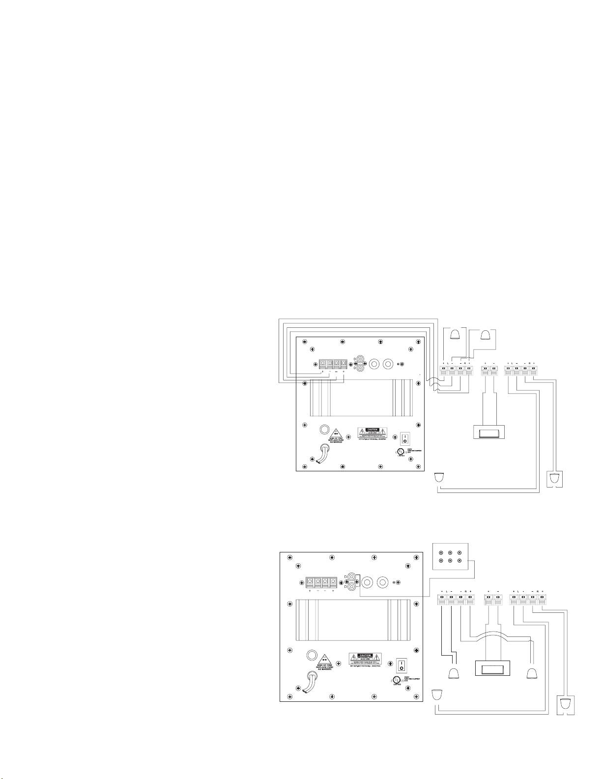
Figure B
WIRING AND CONNECTIONS
Turn off all power to your subwoofer and other equipment
before making any connections. Installation using speaker
level inputs. See (Figure B).
Figure C
FROM AMPLIFIER
FUSE 1A/250 V
FROM AMPLIFIER
L
HI LEVEL IN
L
HI LEVEL IN
1A2 50V
100 WATTS
R
120 VAC
60 HZ
A/V Receiver or Amplier
+ -
LEFT
FR ONT
FREQ
GAIN
L
R
R
LINE IN
MIN MAX
50Hz 150Hz
POWER
ON
OFF
Made In China
FR ONT CENTER SURR OUND
+ -
LEFT
REAR
+ -
RIGHT
FR ONT
+ -
CENTER
FR ONT
RIGHT
REAR
+ -
OUTPUTS
A/V Receiver or Amplier
FREQ
GAIN
L
R
LINE IN
MIN MAX
50Hz 150Hz
POWER
SUB
FR ONT CENTER SURR OUND
Installation with A/V amplifiers and receivers that have
5.1 channel line level output. See (Figure C).
Use and RCA “Y” adaptor to connect both line level
inputs
OSD Audio • 1405 Pioneer St • Brea • CA • 92821 • www.osdaudio.com • Tel (562) 697-2600 • Fax (562) 697-2668
FUSE 1A/250V
1A 250V
120 VAC
100 WATTS
60 HZ
ON
OFF
Made In China
+ -
LEFT
FR ONT
+ -
LEFT
REAR
+ -
CENTER
FR ONT
RIGHT
FR ONT
+ -
+ -
RIGHT
REAR
 Loading...